Design of Variable Steering Ratio for Steer-by-Wire System Based on Driver’s Steering Characteristics


Abstract
1. Introduction
- 1.
- This paper classifies drivers’ steering behavior characteristics through data clustering and identification models and integrates them into the variable steering ratio design of the SBW, achieving personalized steering characteristic matching of “the vehicle adapting to the person”, which significantly improves drivers’ steering comfort and the person–vehicle collaboration performance of vehicles.
- 2.
- A yaw rate gain optimization framework based on multi-objective evaluation indicators is proposed. Combined with genetic algorithms, dynamic adjustment of yaw rate gains for different drivers is carried out, which not only ensures vehicle handling stability but also effectively reduces drivers’ steering operation intensity and safety risks.
- 3.
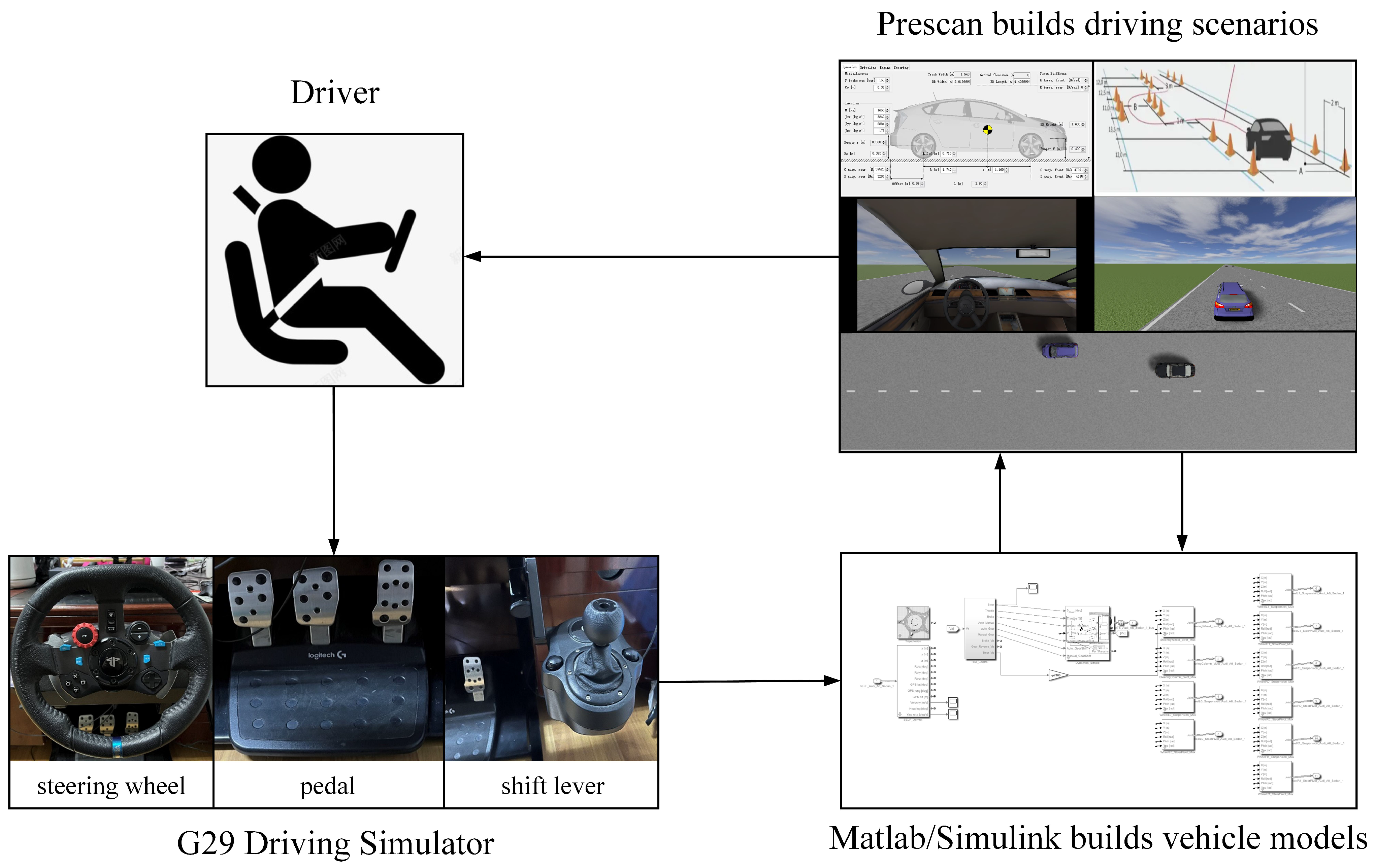
- By constructing a “driver-vehicle-road” closed-loop simulation system, the superiority of the variable gain steering ratio strategy is verified under multiple working conditions. Tests show that this strategy can simultaneously reduce drivers’ operational risks and burdens, enhance vehicle dynamic stability, and provide theoretical and experimental support for the practical application of SBW.
2. Analysis of Factors Affecting Steering Ratio Characteristics
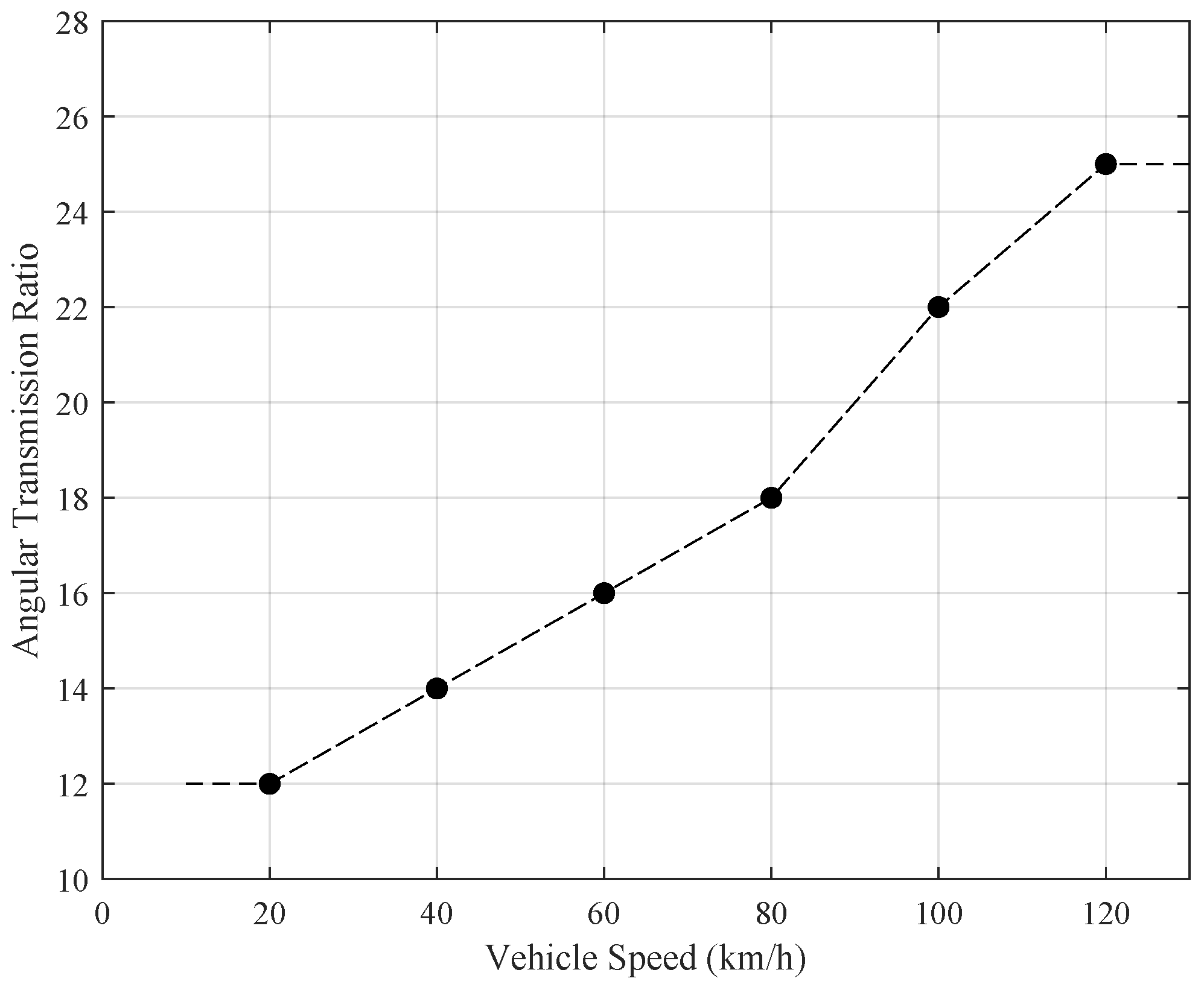
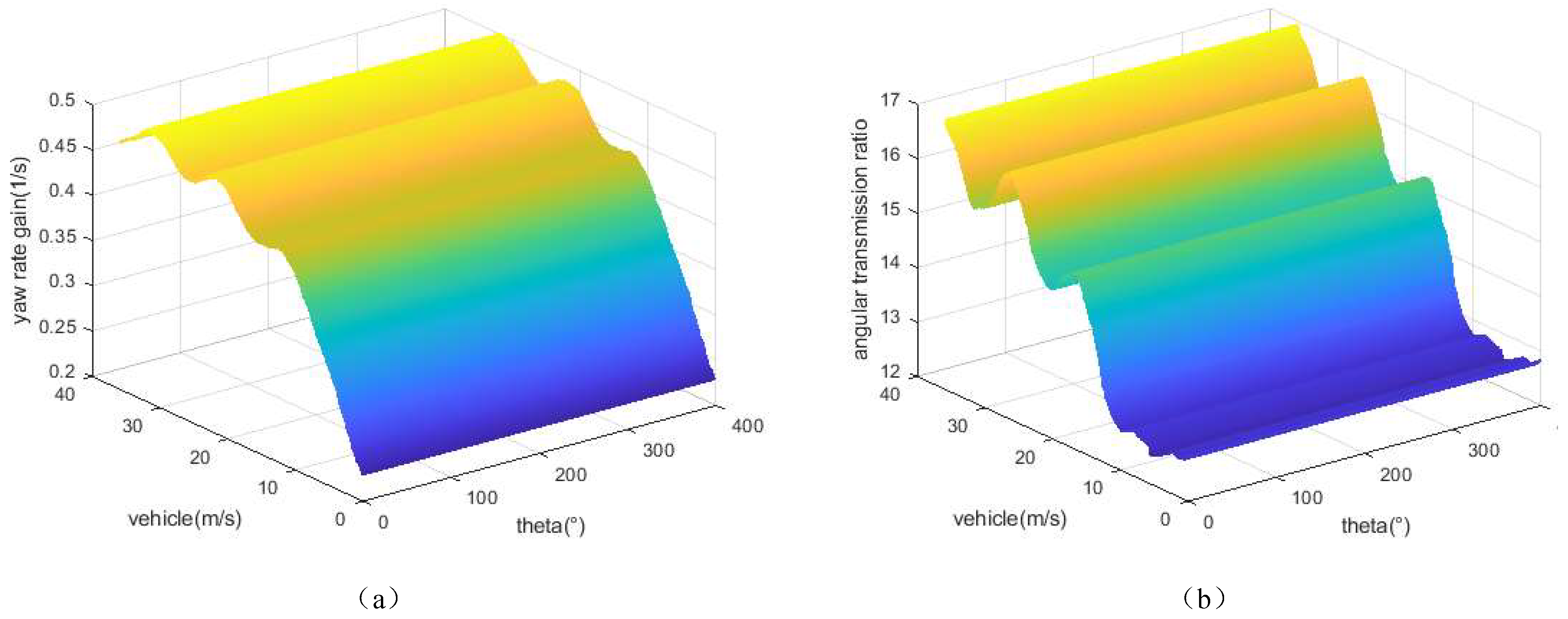
2.1. Influence of Vehicle Speed on the Characteristics of the Steering Ratio
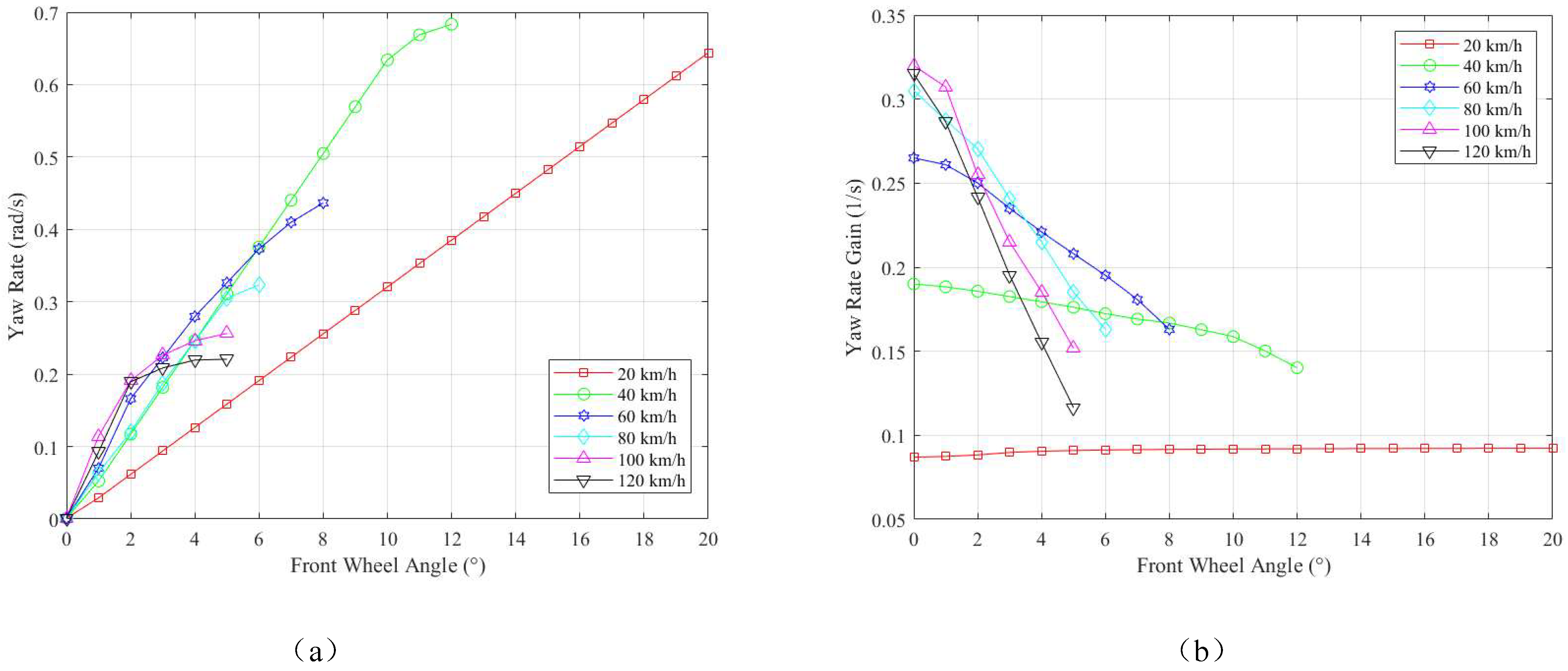
2.2. Influence of the Front Wheel Angle on the Characteristics of the Steering Ratio
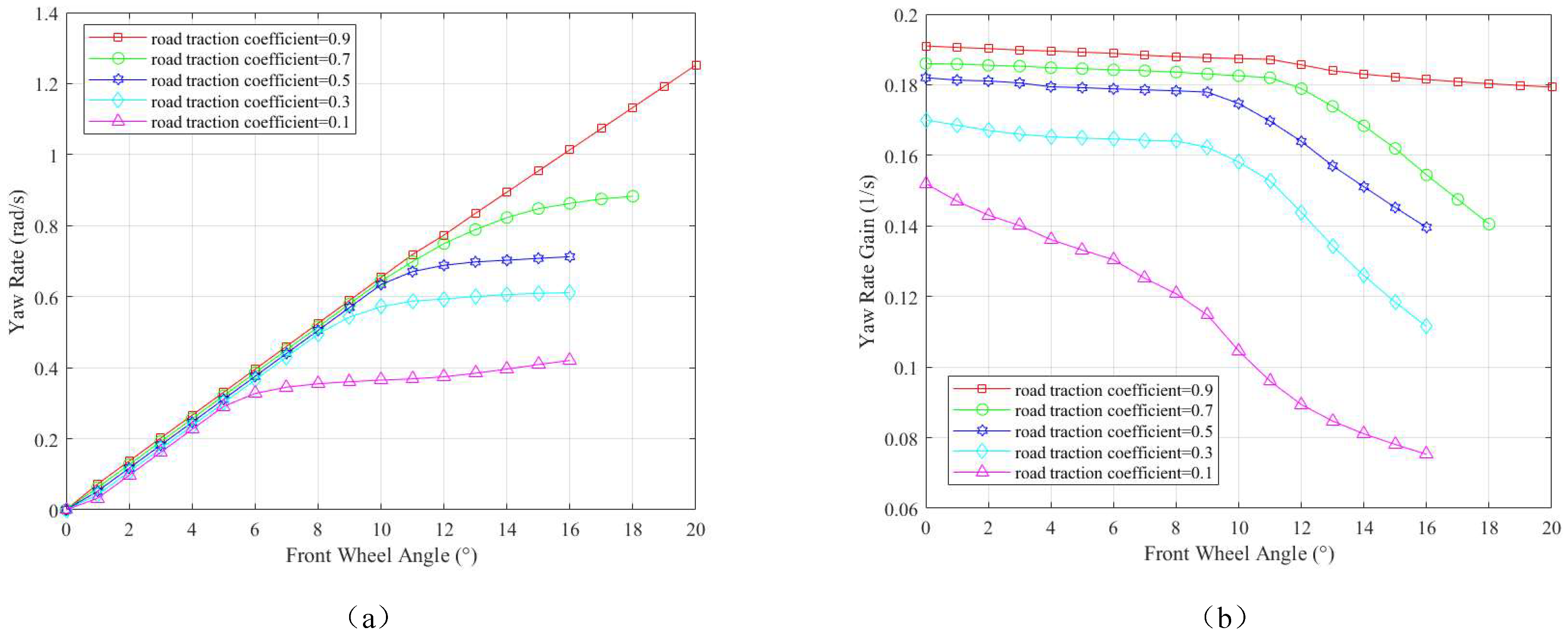
2.3. Influence of Road Traction Coefficients on the Characteristics of the Variable Steering Ratio
3. Design of Variable Gain Steering Ratio
3.1. Yaw Rate Gain Based on Steering Characteristics
3.2. Optimize the Yaw Rate Gain
4. Experimental Verification
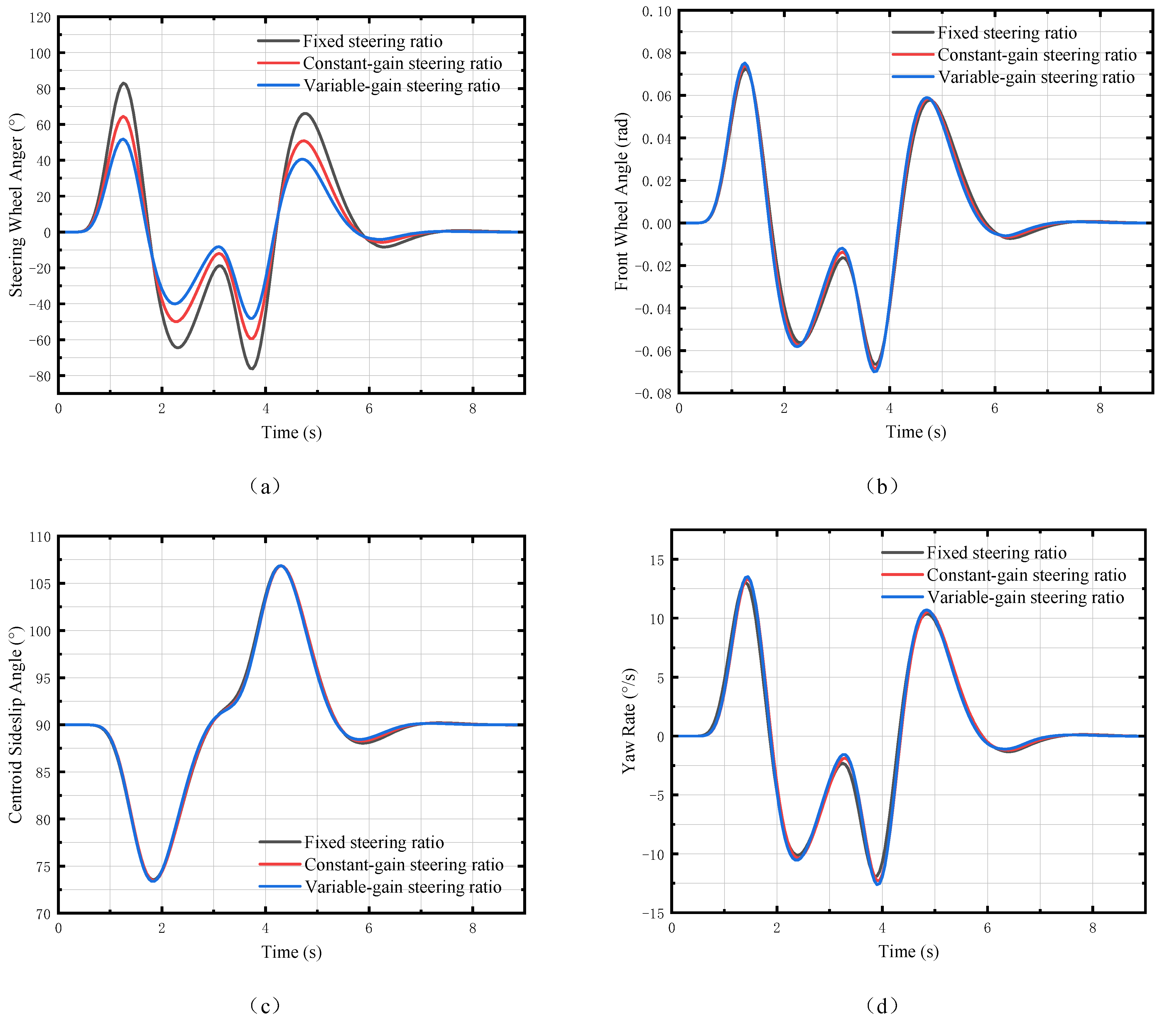
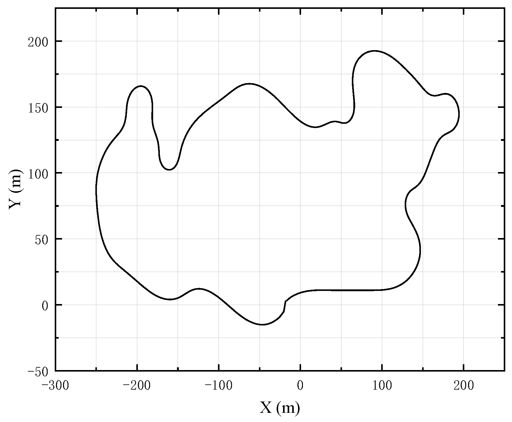
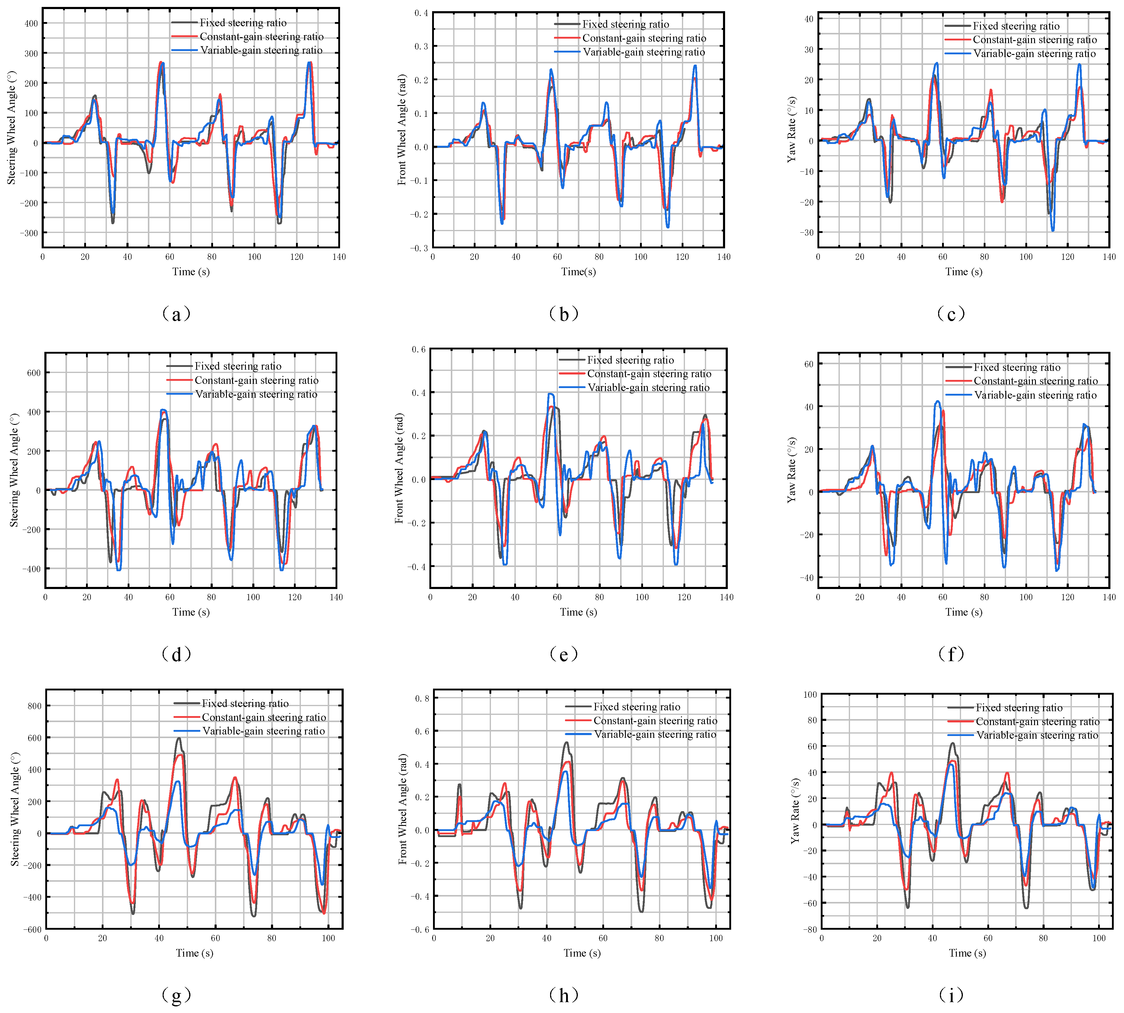
4.1. Trajectory Tracking Test
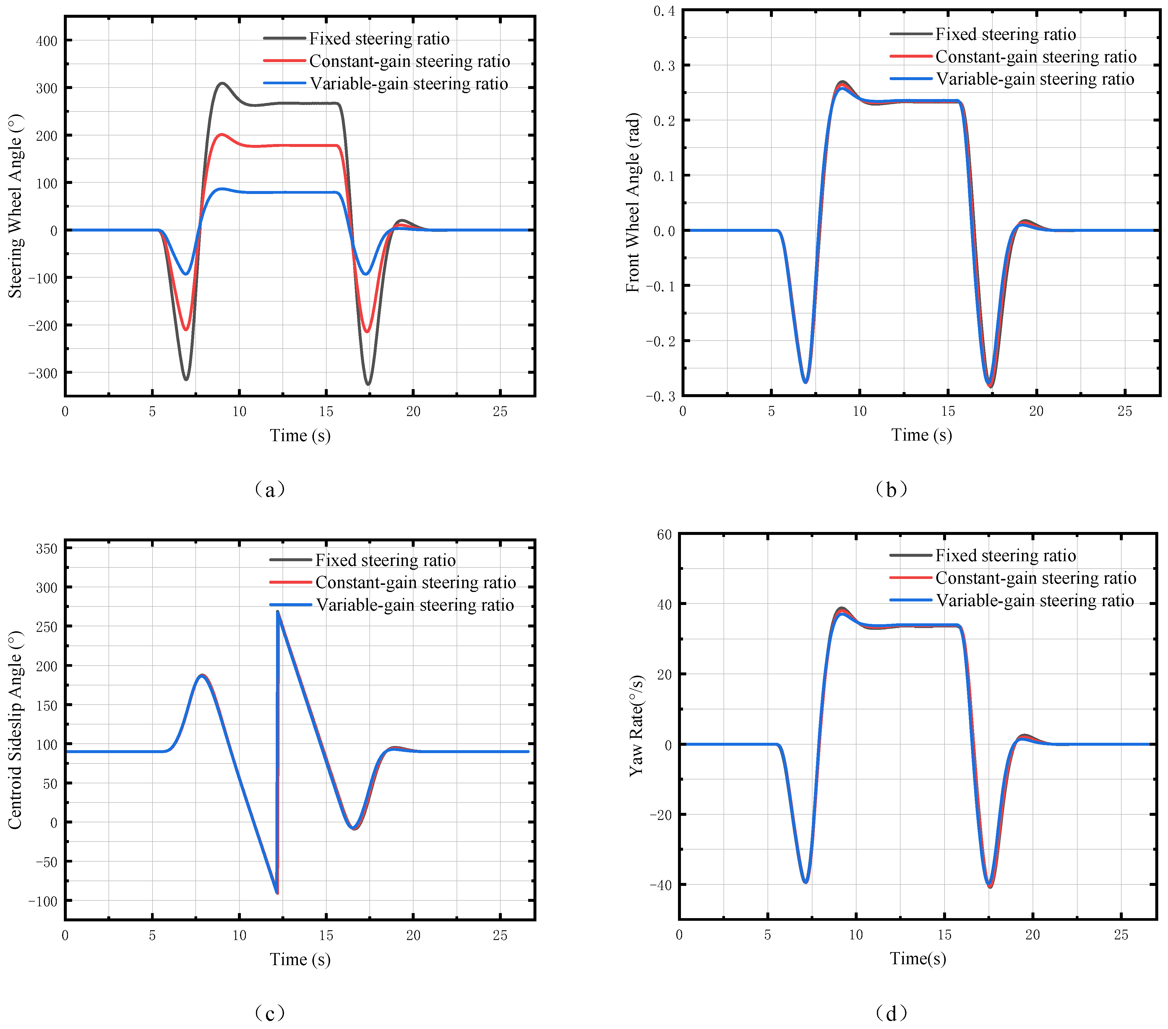
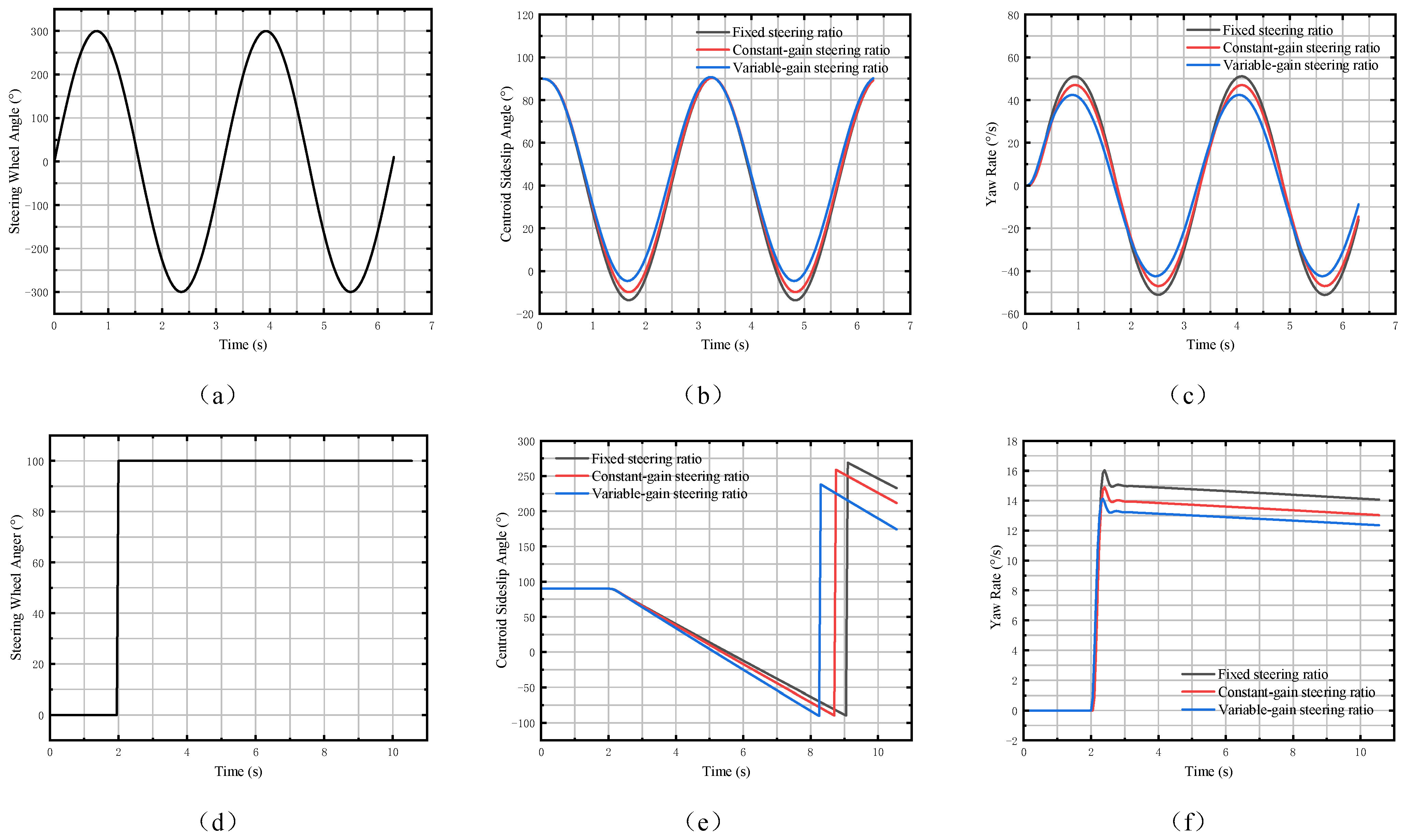
4.2. Handling Stability Test
4.3. Test of Driver’s Steering Characteristics
5. Conclusions
Author Contributions
Funding
Institutional Review Board Statement
Informed Consent Statement
Data Availability Statement
Conflicts of Interest
References
- Mortazavizadeh, S.A.; Ghaderi, A.; Ebrahimi, M.; Hajian, M. Recent developments in the vehicle steer-by-wire system. IEEE Trans. Transp. Electrif. 2020, 6, 1226–1235. [Google Scholar] [CrossRef]
- Llopis-Albert, C.; Rubio, F.; Devece, C.; Zeng, S. Multiobjective optimization framework for designing a steering system considering structural features and full vehicle dynamics. Sci. Rep. 2023, 13, 19537–19546. [Google Scholar] [CrossRef] [PubMed]
- Irmer, M.; Degen, R.; Nüßgen, A.; Thomas, K.; Henrichfreise, H.; Ruschitzka, M. Development and Analysis of a Detail Model for Steer-by-Wire Systems. IEEE Access 2023, 11, 7229–7236. [Google Scholar] [CrossRef]
- Liu, Y.; Liu, Q.; Lv, C.; Zheng, M.; Ji, X. A study on objective evaluation of vehicle steering comfort based on driver’s electromyogram and movement trajectory. IEEE Trans. Hum.-Mach. Syst. 2017, 48, 41–49. [Google Scholar] [CrossRef]
- Liu, H.; Yan, S.; Shen, Y.; Li, C.; Zhang, Y.; Hussain, F. Model predictive control system based on direct yaw moment control for 4WID self-steering agriculture vehicle. Int. J. Agric. Biol. Eng. 2021, 14, 175–181. [Google Scholar] [CrossRef]
- Chen, C.; Zhang, J.; Zheng, H. A modified handling stability control strategy for steer-by-wire vehicles based on variable steering ratio and active front steering control. Proc. Inst. Mech. Eng. Part J. Automob. Eng. 2024, 113–125. [Google Scholar] [CrossRef]
- Zou, S.; Zhao, W. Synchronization and stability control of dual-motor intelligent steer-by-wire vehicle. Mech. Syst. Signal Process. 2020, 145, 106925–106934. [Google Scholar] [CrossRef]
- Zhang, J.; Wang, H.; Zheng, J.; Cao, Z.; Man, Z.; Yu, M.; Chen, L. Adaptive sliding mode-based lateral stability control of steer-by-wire vehicles with experimental validations. IEEE Trans. Veh. Technol. 2020, 69, 9589–9600. [Google Scholar] [CrossRef]
- Wang, J.; Zhou, X.; Zhang, W.; Wang, Z.; Chen, X.; Wang, P. A control strategy for automotive SBW system considering the adaptability of driver’s steering feeling and the choice of steering feeling modes. In Proceedings of the International Conference on Electric Vehicle and Vehicle Engineering (CEVVE 2023), Shenzhen, China, 10–12 November 2023; Volume 2023, pp. 99–106. [Google Scholar]
- Fahami, S.M.H.; Zamzuri, H.; Mazlan, S.A.; Saruchi, S.A. The variable steering ratio for vehicle steer by wire system using hyperbolic tangent method. Appl. Mech. Mater. 2014, 575, 781–787. [Google Scholar] [CrossRef]
- Mughal, H.; Sivayogan, G.; Dolatabadi, N.; Rahmani, R. An efficient analytical approach to assess root cause of nonlinear electric vehicle gear whine. Nonlinear Dyn. 2022, 110, 3167–3186. [Google Scholar] [CrossRef]
- Liu, Z.; Xu, X.; Xie, J.; Wang, F.; Su, P. Variable transmission ratio design of a steer-by-wire system for intelligent vehicles. Proc. Inst. Mech. Eng. Part C J. Mech. Eng. Sci. 2022, 236, 9341–9353. [Google Scholar] [CrossRef]
- Munahar, S.; Munadi, M.; Triwiyatno, A.; Setiawan, J.D. Fuzzy Logic Control System For Fuel-Saving Using Steering Behavior. In Proceedings of the International Conference on Experimental and Computational Mechanics in Engineering, Banda Aceh, Indonesia, 11–12 October 2021; Springer: Berlin/Heidelberg, Germany, 2021; pp. 60–73. [Google Scholar]
- Mohammadzadeh, A.; Sabzalian, M.H.; Zhang, C.; Castillo, O.; Sakthivel, R.; El-Sousy, F.F. Modern Adaptive Fuzzy Control Systems; Springer: Berlin/Heidelberg, Germany, 2023. [Google Scholar]
- Song, X.; Li, H.; Chen, C.; Xia, H.; Zhang, Z.; Tang, P. Design and experimental testing of a control system for a solid-fertilizer-dissolving device based on fuzzy PID. Agriculture 2022, 12, 1382. [Google Scholar] [CrossRef]
- Hopgood, A.A. Intelligent Systems for Engineers and Scientists: A Practical Guide to Artificial Intelligence; CRC Press: Boca Raton, FL, USA, 2021. [Google Scholar]
- Li, Z.; Liu, F.; Yang, W.; Peng, S.; Zhou, J. A survey of convolutional neural networks: Analysis, applications, and prospects. IEEE Trans. Neural Netw. Learn. Syst. 2021, 33, 6999–7019. [Google Scholar] [CrossRef] [PubMed]
- Wang, Y.; Zhang, X.; Ma, G.; Du, X.; Shaheen, N.; Mao, H. Recognition of weeds at asparagus fields using multi-feature fusion and backpropagation neural network. Int. J. Agric. Biol. Eng. 2021, 14, 190–198. [Google Scholar] [CrossRef]
- Huang, J.; Xiao, B. Variable steering ratio design and handling stability research for steer-by-wire forklift. Adv. Mech. Eng. 2019, 11, 168–188. [Google Scholar] [CrossRef]
- Yuan, Y.; Tan, G. Research on handling stability of steering-by-wire system. In Proceedings of the MATEC Web of Conferences, EDP Sciences, Sibiu, Romania, 7–9 June 2017; Volume 139, pp. 198–216. [Google Scholar]
- Cheng, H.; Chen, H.; Xu, S.; Yang, S. Adaptive variable angle control in switched reluctance motor drives for electric vehicle applications. J. Power Electron. 2017, 17, 1512–1522. [Google Scholar]
- Wu, X.; Li, W. Variable steering ratio control of steer-by-wire vehicle to improve handling performance. Proc. Inst. Mech. Eng. Part J. Automob. Eng. 2020, 234, 774–782. [Google Scholar] [CrossRef]
- Nagai, M.; Mitschke, M. An adaptive control model of a car-driver and computer simulation of the closed-loop System. In The Dynamics of Vehicles on Roads and on Tracks; CRC Press: Boca Raton, FL, USA, 2021; pp. 275–286. [Google Scholar]
- Meyer, M.A.; Granrath, C.; Feyerl, G.; Richenhagen, J.; Kaths, J.; Andert, J. Closed-loop platoon simulation with cooperative intelligent transportation systems based on vehicle-to-X communication. Simul. Model. Pract. Theory 2021, 106, 102173–102182. [Google Scholar] [CrossRef]
- Drechsler, M.F.; Sharma, V.; Reway, F.; Schütz, C.; Huber, W. Dynamic vehicle-in-the-loop: A novel method for testing automated driving functions. SAE Int. J. Connect. Autom. Veh. 2022, 5, 367–380. [Google Scholar] [CrossRef]
- Wang, J.; Zhou, X.; Chen, X.; Wang, Z.; Wang, P.; Liu, E. Development of HIL-real vehicle dual steering wheel test platform for automotive SBW system based on variable transmission ratio control. In Proceedings of the International Conference on Electric Vehicle and Vehicle Engineering (CEVVE 2023), IET, Shenzhen, China, 10–12 November 2023; Volume 2023, pp. 88–98. [Google Scholar]
- Zhang, L.; Zhang, Z.; Wang, Z.; Deng, J.; Dorrell, D.G. Chassis coordinated control for full X-by-wire vehicles—A review. Chin. J. Mech. Eng. 2021, 34, 42. [Google Scholar] [CrossRef]
- Wu, T.; Rong, J.; Wang, J.; Sun, W.; Chu, L.; Ge, L. Dynamic Braking Force Distribution Strategy for Steering-Braking Conditions. Automot. Eng. 2024, 46, 1755–1765. [Google Scholar]
- Liu, Y.; Guan, X.; Lu, P.; Guo, R. Research on key issues of consistency analysis of vehicle steering characteristics. Chin. J. Mech. Eng. 2021, 34, 11. [Google Scholar] [CrossRef]
- Zou, S.; Luan, Z.; Zhao, W.; Wang, C. Personalized design strategy of vehicle steer-by-wire characteristics considering driving style. Proc. Inst. Mech. Eng. Part J. Mech. Eng. Sci. 2023, 237, 253–266. [Google Scholar] [CrossRef]
- Alshammari, N.F.; Samy, M.M.; Barakat, S. Comprehensive analysis of multi-objective optimization algorithms for sustainable hybrid electric vehicle charging systems. Mathematics 2023, 11, 1741. [Google Scholar] [CrossRef]
- Deubel, C.; Ernst, S.; Prokop, G. Objective evaluation methods of vehicle ride comfort—A literature review. J. Sound Vib. 2023, 548, 117515–117525. [Google Scholar] [CrossRef]
- Du, Y.; Dong, J. Real-time acquisition and analysis test data of commercial vehicle handling stability based on LabVIEW virtual instrument. J. Phys. Conf. Ser. 2022, 2242, 12–44. [Google Scholar] [CrossRef]

| Parameter | Notation | Unit | Value |
|---|---|---|---|
| Vehicle mass | m | kg | 2372 |
| Distance from the centre of mass to the front axle | a | m | 1.46369 |
| Distance from the centre of mass to the rear axle | b | m | 1.50131 |
| Front wheel lateral deflection stiffness | N/rad | −92,600 | |
| Rear wheel lateral deflection stiffness | N/rad | −110,100 | |
| Moment of inertia about z-axis | kg · m2 | 5337 |
| Gender | 18–25 Years Old | 26–35 Years Old | Over 36 Years Old | |||
|---|---|---|---|---|---|---|
| Num. of People | Avg. Drv. Age (Year) | Num. of People | Avg. Drv. Age (Year) | Num. of People | Avg. Drv. Age (Year) | |
| Male | 4 | 2 | 4 | 4 | 3 | 8 |
| Female | 3 | 1 | 4 | 2 | 2 | 5 |
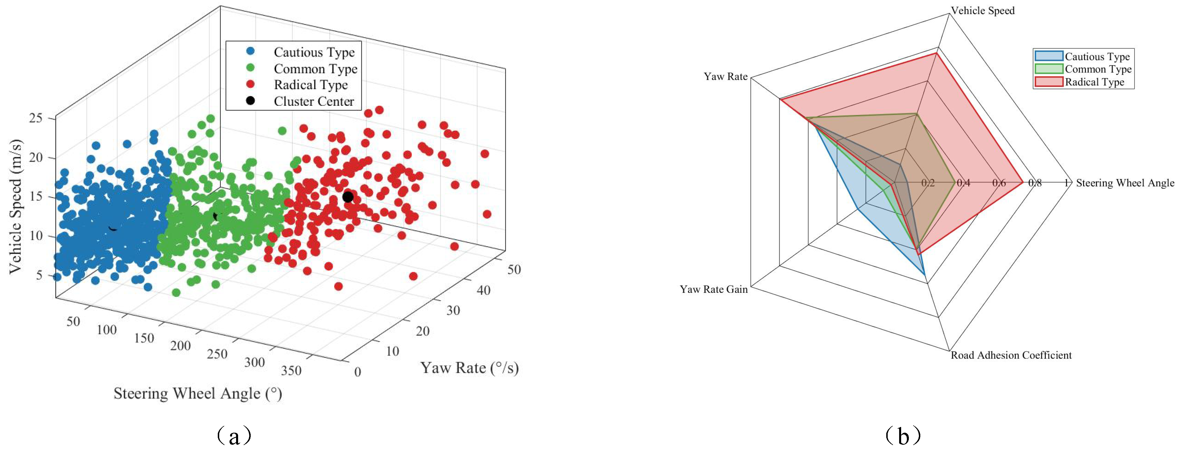
| Steering Characteristics | Steering Wheel Angle (°) | Vehicle Speed (m/s) | Yaw Rate (°/s) | Road Traction Coefficient | Yaw Rate Gain (1/s) |
|---|---|---|---|---|---|
| Cautious Type | 51.47 | 6.85 | 9.71 | 0.61 | 0.42 |
| Common Type | 144.36 | 13.73 | 10.84 | 0.48 | 0.29 |
| Radical Type | 257.68 | 33.59 | 11.68 | 0.52 | 0.21 |
| Driver’s Steering Characteristics | Cautious | Common | Radical |
|---|---|---|---|
| Initial yaw rate gain | 0.48 | 0.29 | 0.21 |
| Initial evaluation value | 1.79 | 3.16 | 5.07 |
| Optimized yaw rate gain | 0.46 | 0.26 | 0.16 |
| Optimized evaluation value | 1.54 | 2.08 | 2.54 |
| Adjustment ratio | 4.17% | 10.34% | 23.81% |
Disclaimer/Publisher’s Note: The statements, opinions and data contained in all publications are solely those of the individual author(s) and contributor(s) and not of MDPI and/or the editor(s). MDPI and/or the editor(s) disclaim responsibility for any injury to people or property resulting from any ideas, methods, instructions or products referred to in the content. |
© 2025 by the authors. Licensee MDPI, Basel, Switzerland. This article is an open access article distributed under the terms and conditions of the Creative Commons Attribution (CC BY) license (https://creativecommons.org/licenses/by/4.0/).
Share and Cite
Yang, K.; Jiang, H.; Chen, L.; Chen, Y.; Tang, B. Design of Variable Steering Ratio for Steer-by-Wire System Based on Driver’s Steering Characteristics. Machines 2025, 13, 489. https://doi.org/10.3390/machines13060489
Yang K, Jiang H, Chen L, Chen Y, Tang B. Design of Variable Steering Ratio for Steer-by-Wire System Based on Driver’s Steering Characteristics. Machines. 2025; 13(6):489. https://doi.org/10.3390/machines13060489
Chicago/Turabian StyleYang, Kun, Haobin Jiang, Long Chen, Yixiao Chen, and Bin Tang. 2025. "Design of Variable Steering Ratio for Steer-by-Wire System Based on Driver’s Steering Characteristics" Machines 13, no. 6: 489. https://doi.org/10.3390/machines13060489
APA StyleYang, K., Jiang, H., Chen, L., Chen, Y., & Tang, B. (2025). Design of Variable Steering Ratio for Steer-by-Wire System Based on Driver’s Steering Characteristics. Machines, 13(6), 489. https://doi.org/10.3390/machines13060489