Article

Structural Analysis of a Modular High-Concentration PV System Operating at ~1200 Suns

by
Taher Maatallah
1,
Mussad Alzahrani
1,
William Cameron
2,
Katie Shanks
2,
Souheil El Alimi
3,
Tapas K. Mallick
1,2 and
Sajid Ali
1,*
1
Mechanical and Energy Engineering Department, Imam Abdulrahman Bin Faisal University, Dammam 31441, Saudi Arabia
2
Environmental and Sustainability Institute, University of Exeter, Penryn Campus, Cornwall TR10 9FE, UK
3
Laboratory of Thermal and Energy Systems Studies (LESTE), National Engineering School of Monastir, University of Monastir, Monastir 5000, Tunisia
*
Author to whom correspondence should be addressed.
Machines 2025, 13(6), 468; https://doi.org/10.3390/machines13060468
Submission received: 20 April 2025 / Revised: 22 May 2025 / Accepted: 26 May 2025 / Published: 28 May 2025
(This article belongs to the Section Machine Design and Theory)

Abstract

The progression of research in concentration photovoltaic systems parallels the advancement of high-efficiency multi-junction solar cells. To translate the theoretical optical framework into practical experimentation, a modular and structurally validated mechanical configuration for a high-concentration photovoltaic (HCPV) system was developed, incorporating boundary conditions and ensuring full system integration. The system incorporates a modular mechanical architecture, allowing flexible integration and interchangeability of optical components for experimental configurations. The architecture offers a high degree of mechanical flexibility, providing each optical stage with multiple linear and angular adjustment capabilities to support precision alignment. To ensure tracking precision, the system was coupled with a three-dimensional sun tracker capable of withstanding torques up to 60 Nm and supporting a combined payload of 80 kg, including counterbalance. The integration necessitated implementation of a counterbalance mechanism along with comprehensive static load analysis to ensure alignment stability and mechanical resilience. A reinforced triangular support structure, fabricated from stainless steel, was validated through simulation to maintain deformation below 0.1 mm under stress levels reaching 5 MN/m2, confirming its mechanical robustness and reliability. Windage analysis confirmed that the tracker could safely operate at 15 m/s wind speed for tilt angles of 35° (counter-clockwise) and −5° (clockwise), while operation at a 80° (counter-clockwise) tilt is safe up to 12 m/s, ensuring compliance with local environmental conditions. Overall, the validated system demonstrates structural resilience and modularity, supporting experimental deployment and future scalability.

1. Introduction

In recent years, concentrated photovoltaic (CPV) systems have been well studied and investigated for energy production. Common concentrating systems are based on either curved surfaces, such as a parabolic dish or parabolic trough, or a Fresnel flat mirror. CPV systems are fabricated to a certain extent to achieve a required optical concentration ratio ( C R ) classified as low ( C R < 10 suns), medium (10 suns < C R < 100 suns), high (100 suns < C R < 2000 suns), or ultrahigh ( C R > 2000 suns) [1]. C R is a measure of the collimated solar energy on the targeted receiver relatively to the total surface area of the aperture, accounting for the optical losses in the ray trajectory path.
Achieving high optical concentration ratios typically requires either a parabolic dish with a maximized surface area [2,3] or a compact design based on either a Cassegrain design or a Fresnel design [4,5]. However, maximizing the primary optic for a parabolic dish challenges the design by adding the weight, the required tracking accuracy and energy load, the minimized acceptance angle, and the optical performance surface relying on the surface’s smoothness and flatness [6,7]. A few attempts toward optimizing the high concentration ratio have been conducted experimentally, but not based on the Fresnel lens design [8]. Although a concentrating compact design reduces the load on the tracking system, the compact design is challenged by its low optical efficiency, complex system tolerance, and alignment, as well as the impact of high thermal stress.
Given the substantial heat flux produced by the focused sunlight, a cooling mechanism capable of sustaining low temperatures on the solar cell is essential. To guarantee maximum electrical productivity and avoid severe thermal deterioration, this is crucial [9]. Since passive thermal sinks are frequently inconvenient in compact multi-stage concentrator systems, active cooling mechanisms that transfer energy to a heat transfer fluid are used instead. Additionally, this makes it possible to retrieve waste heat for later uses, converting the entire system into a hybrid concentration photovoltaic thermal system (CPV/T). Converging microchannels could be used to lessen heat accumulation [10,11,12,13,14]. A HCPV module’s capability to endure wear and tear brought on by operating workloads and climatic conditions makes structural issues extremely relevant [15]. To improve thermal control and lower energy losses, designs that incorporate insulated metal support structures have been investigated. These arrangements reduce possible sources of breakdown and increase overall module durability by improving the removal of heat [16].
To attain the highest optical concentration, solar irradiance, and solar cell efficiency, a sun-tracking instrument with high accuracy is crucial to operating a CPV system based on either a point- or line-focal system. Although a sun tracker is a solution to increase power production when the sun is not within the range of the system acceptance angle, the parasitic energy losses of the sun tracker need to be carefully considered along with the sun tracker’s payload capacity. The sun tracker payload capacity, which is the total weight of the CPV system and the counterbalance, plus the pointing accuracy, are two important factors that must be considered in the CPV system configuration when utilizing a commercial off-the-shelf sun tracker. Several methods of tracking systems are thoroughly discussed in the literature, from manufacturing all the way to control strategies for different solar systems [17,18,19,20,21]. As a result, there is a direct proportional correlation between the level of the concentration ratio and required accuracy for the sun tracker systems.
From the covered literature, it can be deduced that the advancements in HCPV systems have demonstrated significant strides in optical efficiency, but mechanical and structural aspects remain critical to achieving sustained performance under dynamic environmental conditions. Studies such as [22] highlighted that most commercial HCPV systems face challenges related to tracker misalignment under wind loads and thermal expansion effects. Moreover, systems such as those developed by [4,23] focus primarily on optical concentration but overlook mechanical modularity and robustness. The present study is part of a broader research framework aimed at developing a high-performance, compact HCPV system using commercially available components and customized mechanical structures that can break through the record of the effective high optical concentration levels. The current study would contribute to the overall objectives. This work builds upon a series of theoretical and empirical analyses conducted to validate the mechanical integrity, optical performance, and thermal management of a HCPV system, contributing original insights into its structural and experimental feasibility. The optical, thermal, and electrical analyses have been rigorously accomplished to fill any gaps in the literature and extend the significance of the addition to the field of High Solar Concentration Photovoltaic technologies.
In our previously published paper, the main focus was to define the optimum optical setup within the system, allowing room to test the Fresnel lens with the receiver, to test the Fresnel lens with the secondary optics and the receiver (instead of the third optical stage), and to test the setup with three optical stages, including the Fresnel lens, secondary optic, and third optic, and then gathering the concentrated energy in a focal point at the receiver [24]. The optical analysis of the complete system operation, using an array of four Fresnel lenses and a solar cell dimension of 5.5 mm × 5.5 mm, demonstrated the highest effective concentration ratio achieved experimentally so far, reaching 1291 suns [25]. The collected experimental data showed that the prototyped high-concentration photovoltaic system generated an effective concentration 27% higher than the latest development presented in the literature [4]. To determine whether an adequate dissipation system can be effectively integrated, a detailed thermal analysis is essential. A numerical and experimental study has been conducted. A novel simulation model to provide an in-depth understanding of the functionality of a concentrated photovoltaic thermal hybrid system with serpentine-based cooling systems has been developed [26]. The simulated results have been validated through indoor experimentation. The effectiveness of cooling was evaluated through the maximum thermal stresses generated in the multi-junction solar cell. The double serpentine design was deemed the highest performing, primarily because of the single serpentine’s excessive pressure drop. Copper as the heat sink material yielded superior performance because of its higher thermal conductivity. The maximum total exergetic efficiency achieved by the receiver was ~10.9% with this configuration. All serpentine-based cooling systems could maintain the recommended operating temperature below 110 °C. To further optimize the performance of the HCPV system, a four-domed optic bonded directly with an AZUR SPACE (3C44A) (AZUR SPACE Solar Power GmbH, Heilbronn, Germany) 5.5 mm × 5.5 mm multi-junction solar cell (40.5% @ 1000 suns) was developed and experimentally tested, enhancing the homogenization of rays and maximizing the acceptance angle of the high-concentration photovoltaic system [27]. In the present study, the structural configuration was exclusively tested and optimized through the simulation and experimental setup, with a focus on modularity, load resistance, and system adaptability. The system integrates reinforced mechanical framing with optimized load distribution and precise angular adjustment features, facilitating interchangeable optical stage configurations. The modular architecture emphasizes mechanical flexibility [28] to accommodate future upgrades or optical configuration changes [29]. The system demonstrates superior structural performance, with a high load-bearing capacity and minimal deformation under elevated stress conditions. The use of commercially available stainless-steel components and modular fabrication techniques contribute to long-term operational efficiency without sacrificing mechanical durability. Windage analysis and counterbalance performance exceed the benchmarks reported in comparable studies, confirming system resilience under realistic environmental forces. Compared to the conventional 42 × 42 cm solar panels, the modular high-concentration photovoltaic (HCPV) system offers clear advantages, achieving an effective optical concentration ratio of up to 1291 suns and enabling higher power density at the receiver using a high-efficiency multi-junction solar cell. Its scalable mechanical architecture supports adaptability in various experimental and deployment scenarios, while active cooling integration ensures thermal stability and prevents degradation of solar cells. Collectively, these validated features demonstrate the system’s structural robustness, modular configuration, and readiness for field deployment. The structural design also considers compatibility with thermal sink architectures for CPV/T integration, as explored in our previous work [26]. This continuity ensures that the mechanical and thermal domains are cohesively developed. The novelty of this work lies in the structural modularity that accommodates multiple optical configurations, enabling experimental reconfiguration without requiring complete system redesign, a flexibility absent in most existing CPV systems.
This paper presents the structural configuration, fabrication process, and experimental deployment readiness of a compact HCPV prototype system prepared for outdoor testing at Penryn Campus, University of Exeter. The study outlines the system’s mechanical boundary conditions, followed by optical simulations to determine the optimum positioning of the Fresnel lens and subsequent optical elements within the system frame. The optical stages are described in terms of their functional roles and alignment flexibility. Material selection is based on the use of commercially available components with minimal machining requirements to ensure ease of assembly and scalability. A detailed description of the selected sun tracker is included, highlighting its payload capacity and tracking precision. The interlink mechanical structure (beam assembly), developed to support both the HCPV system and counterbalance the mass of the tracker, is subjected to numerical static load and wind impact analysis. The structure of the paper is organized as follows: Section 2 presents the structural configuration and system overview. Section 3 presents the optical subsystem. Section 4 discusses the materials selection criteria. Section 5 elaborates on the sun-tracking system and its capabilities. Section 6 provides the results and analysis. Finally, Section 7 concludes the study with key findings.

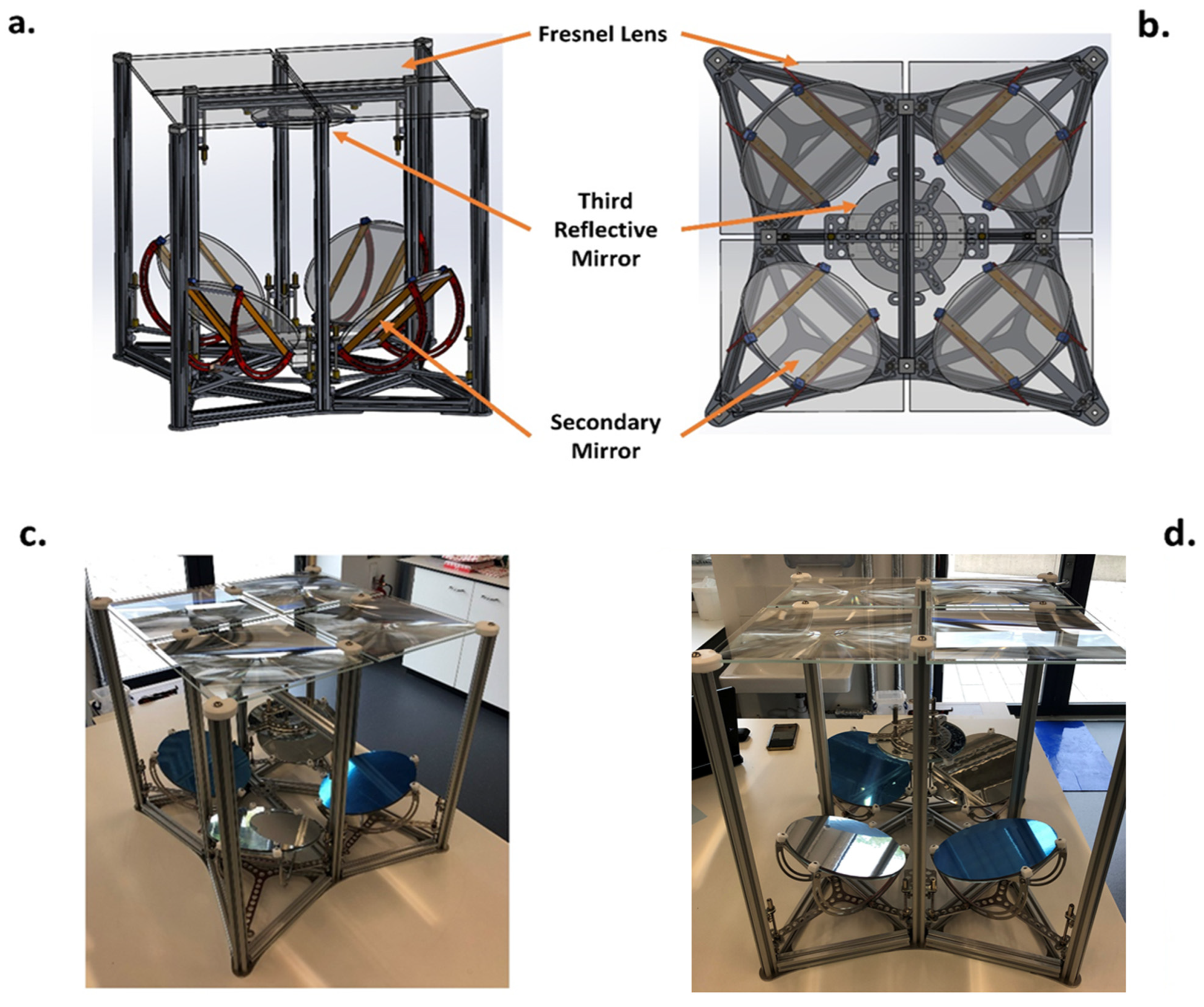
2. Structural Configuration and System Overview

The high-concentration photovoltaic (HCPV) system was developed through a structured implementation framework that accounts for interdependencies among three key components: the optical module, sun tracker, and supporting mechanical structure. Initial boundary conditions were defined to ensure mechanical compatibility, optical alignment flexibility, and load-bearing robustness. These conditions include the following:
  i.
The framework is based on four pieces of Fresnel focal point lenses—Silicon on Glass (SOG).
 ii.
Fresnel focal points are the settled input.
iii.
The framework is based on one central third stage and/or receiver.
iv.
The framework can work with three and/or four optical interfaces.
 v.
All secondary optical stages are mechanically adjustable, offering a broad range of degrees of freedom.
vi.
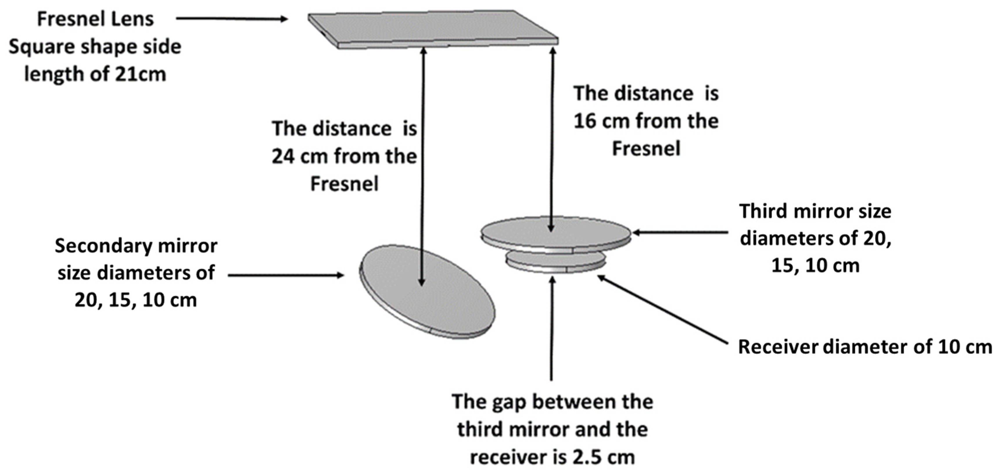
Reflective surfaces in the secondary and third stages are interchangeable, with diameters of 10, 15, and 20 cm and thicknesses ranging from 4 to 6 mm.
vii.
The HCPV system is configured for testing with a sun tracker capable of supporting the system and counterbalance weights.
The system’s central structural layout follows a diamond-shaped configuration, with four triangular sections extending from its core. This configuration was implemented to maintain a clear optical path and avoid any mechanical obstructions that could interfere with concentrated light transmission. The complete HCPV prototype is shown in both CAD model views and actual assembly photographs in Figure 1. Figure 1a,b illustrates the structural model generated in SOLIDWORKS, while Figure 1c,d shows the actual assembled system. The support structure was fabricated using 20 × 20 mm aluminum strut profiles with 6 mm slots, selected for their lightweight properties and minimal beam deflection under load. The system includes eight vertical struts (500 mm each), twelve horizontal struts forming the triangle bases (210 mm each), and two extended horizontal struts (324 mm each) supporting the third-stage optics and receiver. This modular structural arrangement ensures mechanical stability while supporting the precise alignment of optical components for system testing.

3. Optical Stages

Concentrating light into high factors requires a system with a high degree of freedom to allow correctness and high accuracy of directing and redirecting concentrated light—the focal length. To set up the accuracy of the optics in terms of distances between the primary stage optic (Fresnel lens) and the subsequent optics and angles of the secondary optics, optical simulation in the COMSOL Multiphysics software (Version 6.2) was carried out, reaching the maximum C R with countless trials of distance refinement to reach the optimum adjustment of optics, as shown in Figure 2.
Ray tracing simulations in COMSOL were used to determine optimal distances and angles for each optical stage, refining tolerances within ±1.5 mm for lateral placement and ±2° for angular orientation to ensure convergence at the 5.5 mm2 receiver.
The optimum distance between the Fresnel lens and secondary optic is 24 cm, the optimum distance between the Fresnel and third optic stage is 16 cm, the defined gap between the third optic and the receiver is 2.5 cm, and the angular orientation of the secondary optic is 35 degrees, as illustrated for ¼ of the HCPV in Figure 3. Afterward, the linear correlation between the short circuit current (Isc) and the direct solar irradiance (DNI) is the experimental measure through which the minimum adjustment and alignment will be carried out to assure the maximum value of Isc.

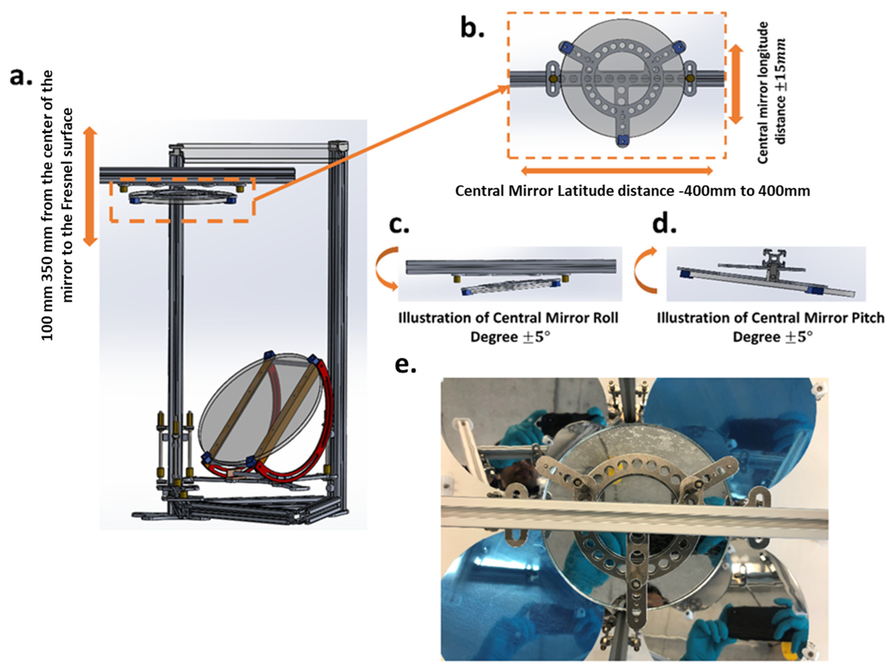
3.1. Secondary Optical Stage

The secondary mirror frame redirects concentrated light from the Fresnel lens to the third-stage reflective mirror, enabling multi-stage optical focusing, Figure 4. The assembly supports three degrees of freedom for experimental alignment. First, the secondary mirror is adjustable vertically from the center of the mirror to the center of the Fresnel lens, which can travel as close as 10 cm to the Fresnel and as far as 35 cm. Second, it can be adjusted angularly between 0   a n d   70 ° . Last, the entire frame base has a yaw angle of ± 5 ° . The secondary mirror frame is equipped with three thumb nuts, an intermediate between the aluminum strut and the secondary mirror mount, travelling along the vertical strut utilizing two inside brackets of 6 mm per thumb nut. Every ¼ of the system is built on one apex node and two twin-apex nodes to be linked with neighboring quarters.

3.2. Third Optical Stage
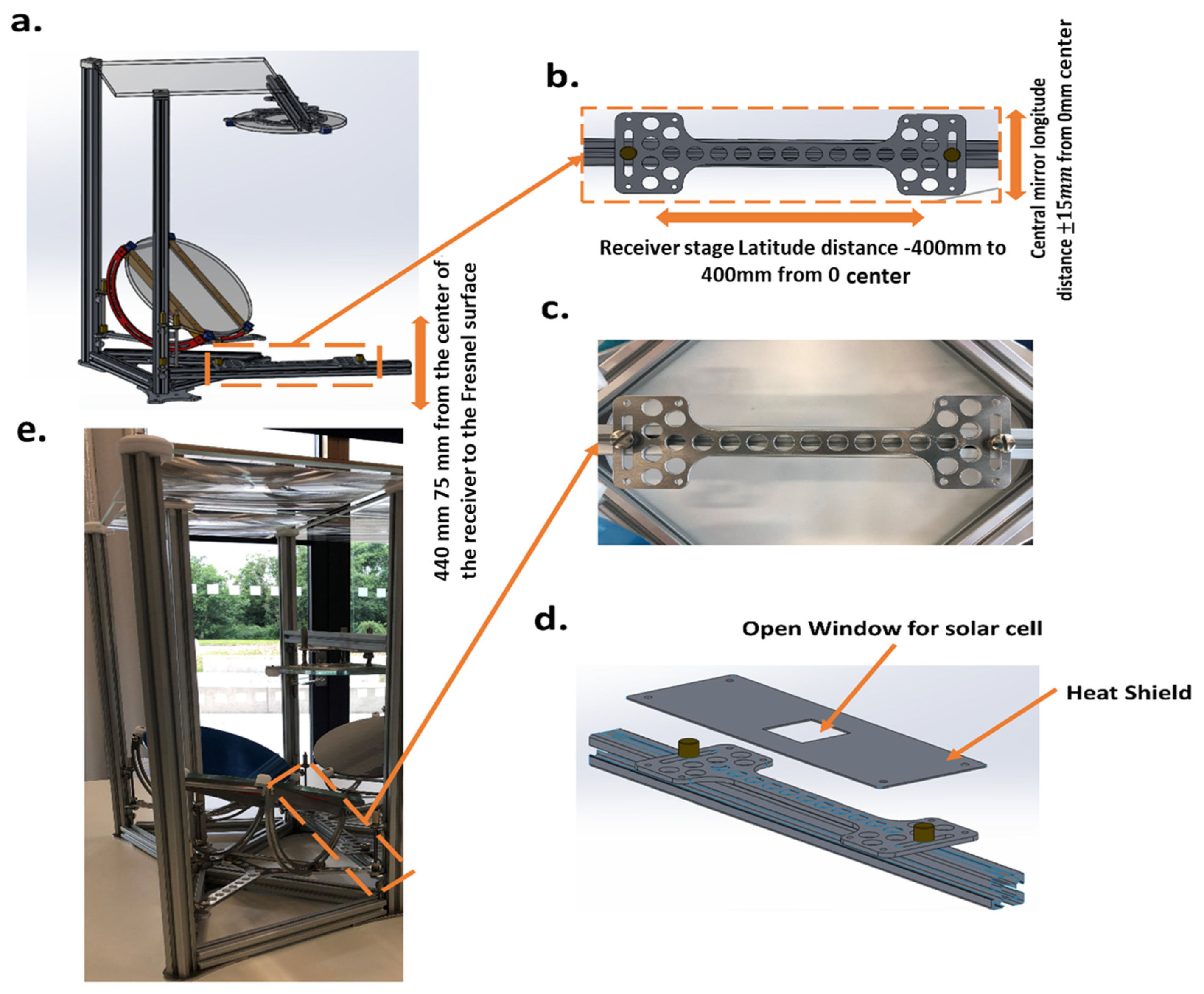
The third-stage reflector aggregates light from all four secondary mirrors and features multi-axis adjustability to support accurate convergence onto the receiver. The mirror is mounted to a horizontal strut and is vertically adjustable via thumb nuts for precision focusing. This stage incorporates five degrees of freedom to enable precise control over optical beam convergence. The third stage allows vertical adjustment with a similar range as the secondary stage, as in Figure 5a, and horizontally in latitude and longitude distances between ± 40 mm and ± 15 mm from its center, respectively, as in Figure 5b. Additionally, the base of the third reflective mirror has roll and pitch angular tunings of ± 5 ° from its center, as in Figure 5c,d. Figure 5e shows the physical implementation corresponding to the adjustments shown in Figure 5b. The third stage can function either as a reflective optical stage or be removed to allow direct coupling of the receiver. This flexibility was included to support configurations targeting high concentration using four optical stages.
A comparative analysis of different optical stages of the system is shown in Table 1. The observed trend clearly shows a reduction in efficiency with each additional optical stage. Based on this trend and preliminary simulations, we expect the optical efficiency of a 4-stage configuration to be further reduced and reach 22%. This comparison has now been added to the revised manuscript to address this important point. A dedicated Zemax analysis will be conducted in future iterations.

3.3. Receiver Stage

The receiver stage, aligned with the third optic, provides three degrees of freedom for focal alignment and heat sink scaling. Two of these are similar to the latitude and longitude movements in the third stage, as in Figure 6b,c, and the last one is a vertical transfer becoming close to 7.5 cm to the third stage and as far as 44 cm, as in Figure 6a,e. The mounting platform accommodates interchangeable thermal sinks for various heat dissipation configurations based on the optical concentration levels. A protective heat shield was integrated to prevent thermal damage to mechanical elements in case of optical misalignment, exposing only the active cell area to concentrated rays, as seen in Figure 6d.
Uniform intensity across the 5.5 mm2 cell area is crucial. While initial tests indicate homogeneity, future setups will use a movable pinhole mask to map irradiance distribution and optimize optical alignment accordingly.

4. Materials Selection

All the interior brackets of 6 mm are made of zinc-plated steel. Both aluminum strut profiles, 20 × 20 mm, and interior brackets are sourced as off-the-shelf components from the KJN Aluminum Profiles company (Leicester, UK) [30]. The warm shield, central reflect outline, central reflect mount plate, auxiliary reflect fragment, pinnacle hub, twin-apex hub, and auxiliary reflect mount were fabricated from aluminum (AL5083) and manufactured using laser cutting by Laser Exactness Cutting Company (Birmingham, UK) [31]. All fasteners and mechanical fittings are obtained from RS Components Ltd. (Corby, UK) [32]. Erosion inhibitors (ULTRA Tef-Gel), essential for stainless-steel screws to aluminum strings, were applied, as the system is intended for outdoor operation, where this gel offers waterproof grease with anti-corrosion and anti-seize properties and does not break down in salt water or detergents.
The primary optical components, the SOG-Fresnel lenses, were manufactured by Orafol Fresnel Optics [33]. The Fresnel lens is made of un-tempered low-iron glass of a working distance 45 m, clear aperture of 21 × 21   c m 2 , and glass plate dimensions of 23   c m × 23   c m × 4.0   m m . For the secondary and third stage optics, the tempered low-iron glass and Pilkington mirror were produced and coated by Cornwall Glass Company (Cornwall, UK) [34]. The manufactured glass was a circular mirror of 5 cm, 10 cm, and 15 cm diameter with a thickness of 6 mm. The tempered low-iron glass for the secondary and third stage mirrors was coated with a high-reflectivity film. All components were selected and assembled to ensure structural integrity and optical performance for outdoor experimental testing under high-concentration conditions.

5. Sun Tracker: Aspects and Limitations

The high concentration necessitates a high-precision tracking system to achieve a very small focused solar spot with minimal dispersion at the focus. The optical performance stability depends on numerous variables, one of which is the tracking system accuracy. The sunlight divergence angle of ± 0.265 ° induces a slight acceptance angle where a sun tracker with a comparable pointing precision ought to capture all the incoming solar radiation. Other factors, such as environmental disturbances and structural flexing, also influence tracking precision, often necessitating a wider acceptance angle than the solar divergence angle to maintain optical alignment.
Two sun tracker models fabricated by Kipp & Zonen (Delft, The Netherlands) were explored for integration with the HCPV system for continuous three-dimensional following. First, the SOLYS2 sun tracker was chosen for this investigation, where SOLYS2 offers flexible mounting options permitting a wide range of radiometers to be mounted, as appears in Figure 7a. The SOLYS2 sun tracker has both wire and Ethernet ports for communication and information procurement, including data acquisition, to allocate the sun position. While the SOLYS2 sun tracker was initially considered, due to its payload of 20 kg, the HCPV framework can only be 10 kg, and a balance weight of 10 kg must be added to ensure system stability and tracking accuracy. As a result, the SOLYS Gear Drive (GD) by Kipp & Zonen was chosen rather than the SOLYS2. The SOLYES (GD) is better suited because it retains all the features of the SOLYS2; additionally, its payload of 80 kg is greater, and it has a torque of 60 N.m, precisely indicating the sun during higher windage and worse climate conditions. The SOLYS GD can be introduced on the same cast aluminum SOLYS2 tripod. Nevertheless, if the full weight of the tracker and the associated HCPV system and radiometers is over 50 kg and/or there is huge windage, a heavy-duty tripod floor stand fitted with a height expansion tube is proposed by the producer to be utilized, as in Figure 7b. Table 2 presents a comparative overview of the key specifications of the two sun trackers considered.

6. Results and Analysis

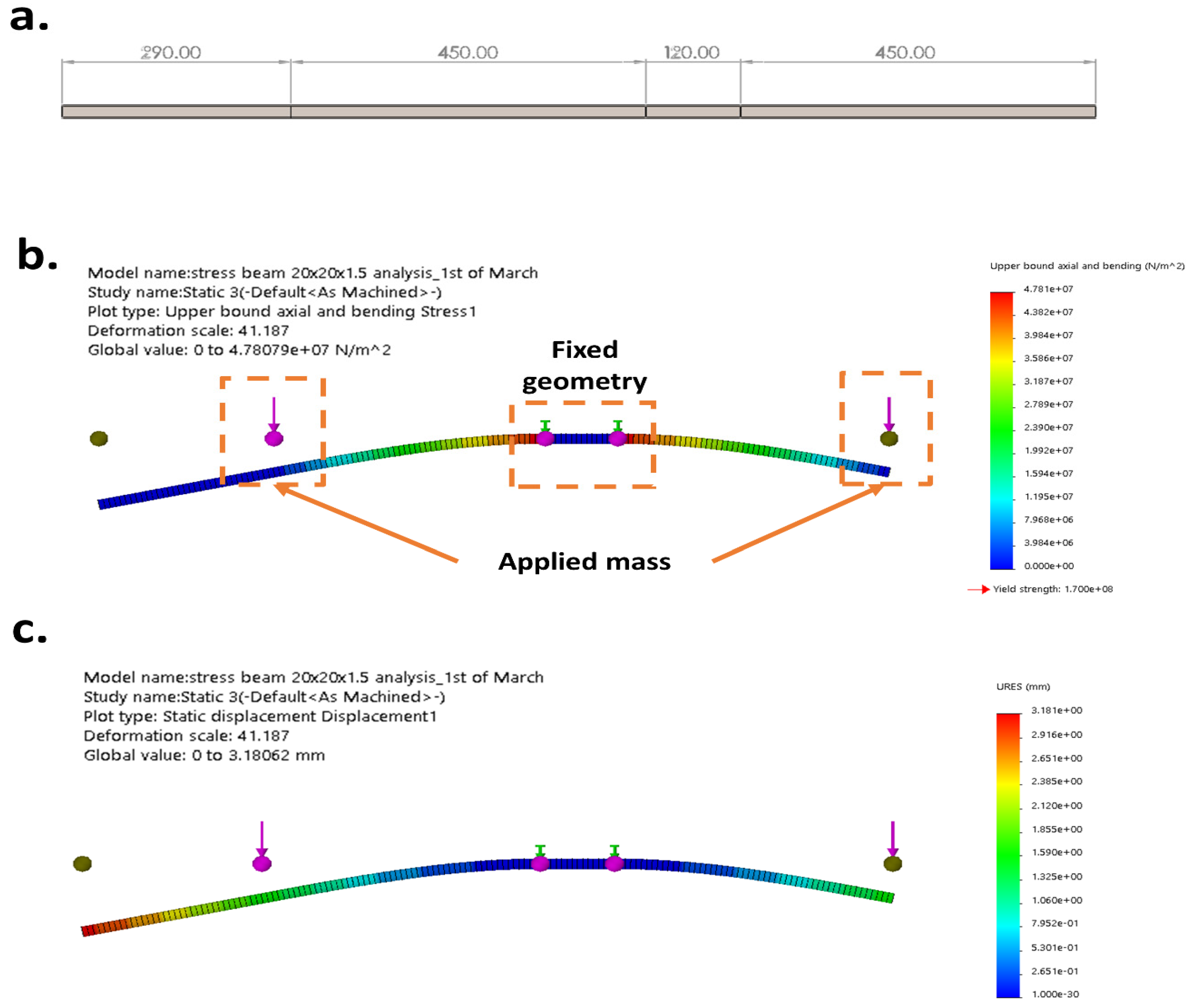
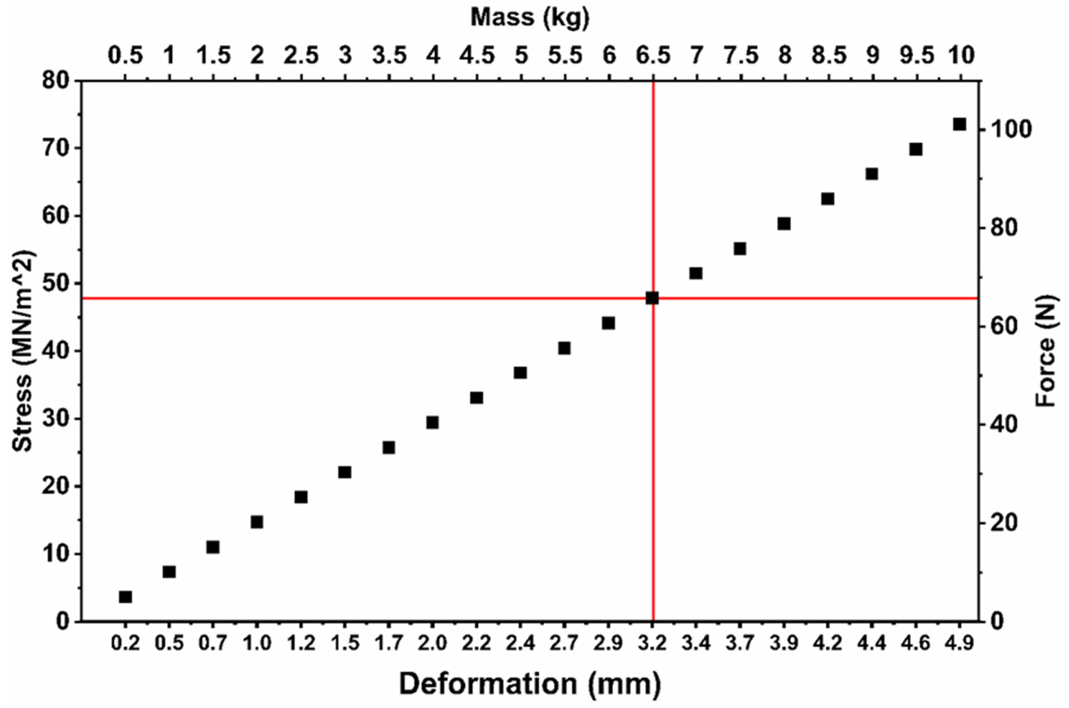
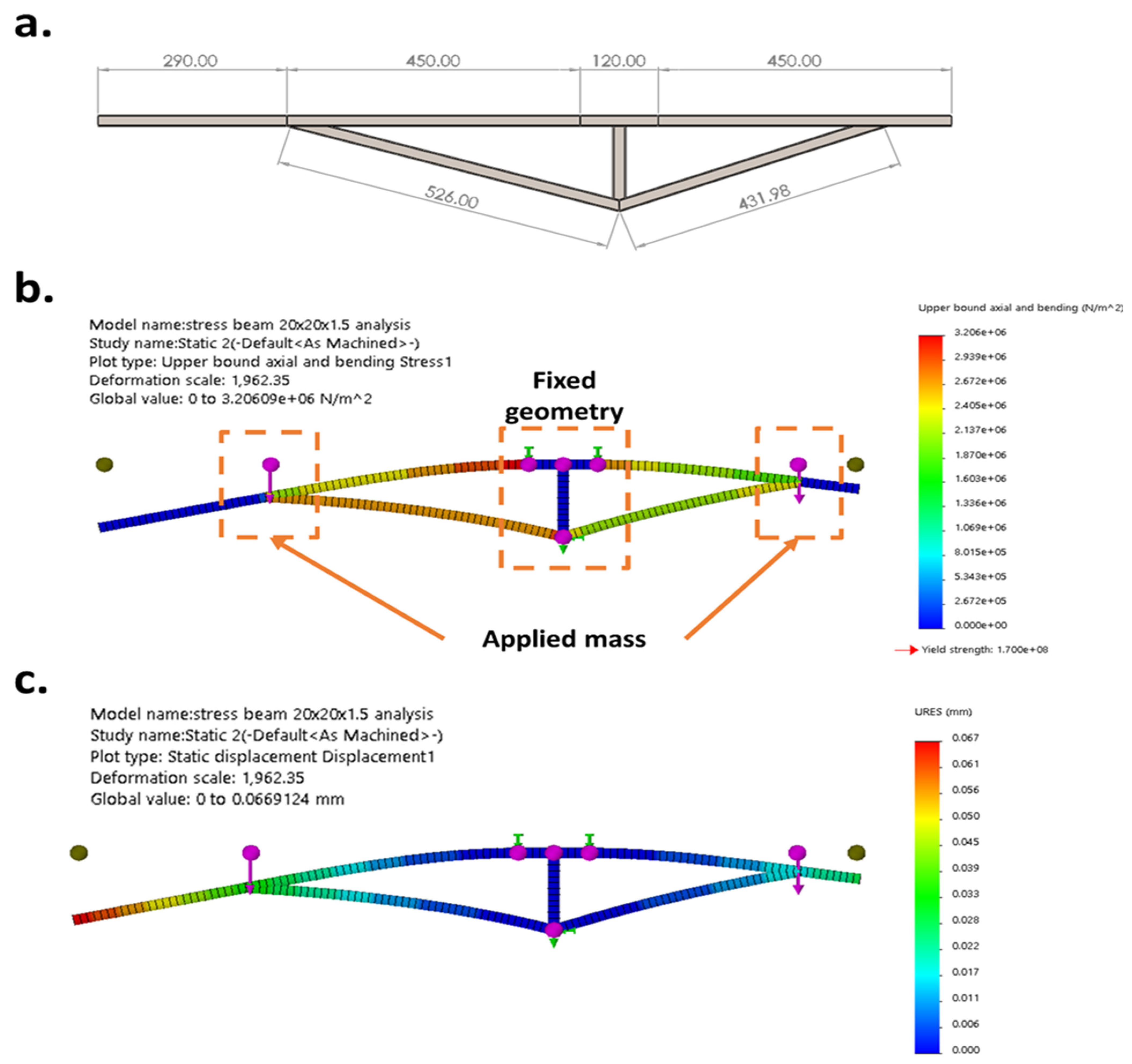
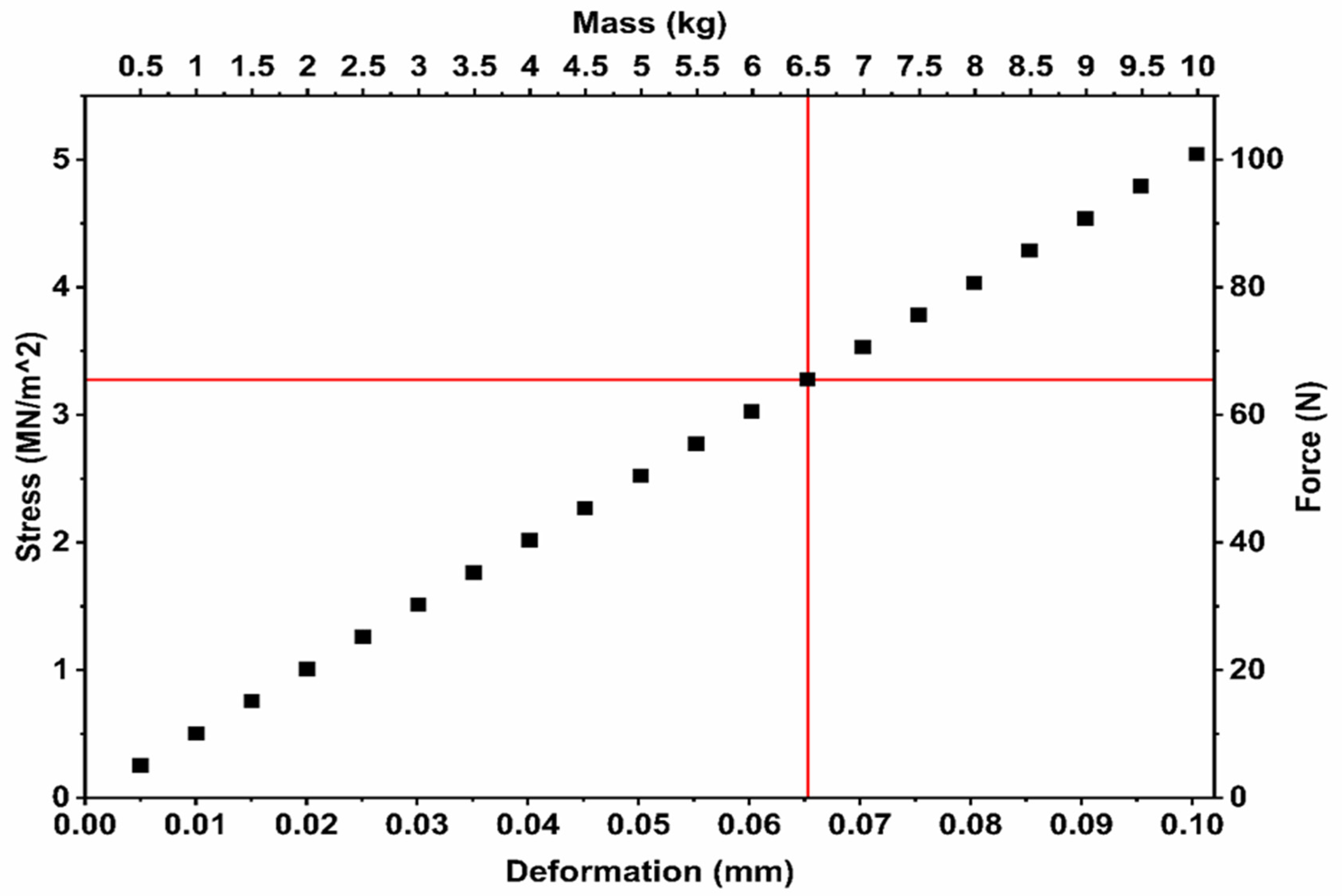
6.1. Interlink Mechanical Structure—Beam Analysis

To connect the high-concentration photovoltaic (HCPV) system to the sun tracker, two tubular beams are used to support the system and its counterbalance on opposite sides. These weights represent the HCPV assembly and its counterbalancing mass. The selected arms are hollow square tubes of 20   m m × 20   m m × 1.5   m m , made of stainless-steel grade 316. A straight tubular beam configuration was initially considered for simplicity. A static load analysis was conducted to validate the beam’s suitability under the expected loading conditions. The static simulation confirmed that the resulting stress levels, under applied system and counterbalance weights, remained below the material yield strength. Importantly, the resulting deformation was below 0.01 mm, ensuring alignment accuracy and mechanical stability. The tube geometry is illustrated in Figure 8a, where the scaled-up stress distribution and deformation distribution results are shown in Figure 8b,c, respectively. The principle of moments was applied to determine the appropriate arm lengths needed to balance the HCPV system and counterweight. This helped to define the arm length with the corresponding applied mass. The simulation results present the maximum stress and deformation for a 6.5 kg applied mass on each side, with the analysis conducted on a single beam.
The tube beam was evaluated for an applied mass ranging from 0.5 kg to 10 kg in increments of 0.5 kg. The red crossline in the plots indicates the reference points corresponding to each applied mass. The resulting maximum deformation ranged from 0.2 mm to 4.9 mm, depending on the applied mass. The maximum stress value ranged between 3.7 M N m 2 and 73 M N m 2 . These results are fully illustrated in Figure 9.
The previous configuration produced a deformation of 3.2 mm, leading to unacceptable optical misalignment. Therefore, the structure was reconfigured to reinforce the tube beam and improve stiffness. Reinforcement was implemented by adding a diagonal tube beam, forming a triangular geometry to enhance structural rigidity. The geometric configuration is shown in Figure 10a. Static load analysis was repeated on the modified configuration using the same applied masses. Figure 10b,c shows the stress and deformation distribution, respectively.
The reinforced tube beam was re-evaluated under an applied mass ranging from 0.5 kg to 10 kg in increments of 0.5 kg. The red crossline in the plots indicates the reference positions corresponding to the applied masses. The resulting maximum deformation ranged from 0.005 mm to 0.1004 mm across the tested load range. The maximum stress value varied between 0.25 M N m 2 and 5.04 M N m 2 . These findings are fully illustrated in Figure 11. The reinforced configuration demonstrated a significant improvement in structural performance, supporting up to 10 kg of applied mass with deformation remaining below 0.1 mm. It should be noted that while the simulation confirms minimal deformation (<0.1 mm), physical validation via strain gauges and deflection sensors is planned for the next prototype deployment phase.
The geometry of the stabilizing structure, specifically the reinforced triangular beam configuration, was derived through iterative structural simulations combined with the principle of moments. The primary design objective was to minimize deformation under the applied load of 6.5 kg on both the HCPV assembly and counterweight sides while maintaining a compact and modular profile. A diagonal stainless-steel tube was introduced between the midpoint of the main beam and the lower support junction, forming a rigid triangular section. This diagonal placement was optimized to reduce beam deflection by over 96%, bringing the deformation from 3.2 mm down to 0.1 mm under load. The selection of the tube length (460 mm) and angle (~45° to the horizontal axis) was based on balancing torque resistance, ease of assembly, and alignment compatibility with the sun tracker mount. The finalized geometry ensures high structural stiffness without compromising the system’s transportability or modular integration.
Although diagonal reinforcement is a known method, its modular integration with the optical assembly while maintaining alignment tolerances under field conditions contributes to practical system robustness and ease of deployment.

6.2. System Component Integration and Spatial Consideration

The high-concentration photovoltaic (HCPV) system, counterbalance arm, and mass were integrated with the sun tracker and spatially modeled for deployment. This integration was conducted to assess the spatial footprint required for full system operation, considering the azimuthal rotation and solar elevation. Figure 12a,b presents the full system model and angular motion envelope. The sun tracker rotates a lap when it is powered up, starting with 270° to the left and then another 270° to the right to take off from a home position. To accommodate the full range of motion, a minimum clearance of 2 m in diameter and 2 m in height is required for safe operation of the HCPV system with the sun tracker. This spatial requirement is met by the installation site located on the north light roof of the Environmental and Sustainability Institute (ESI), Penryn Campus, University of Exeter. The HCPV system is mounted via the reinforced tube beam, with the alignment configured to position the system’s center of mass 250 mm above the top surface of the Fresnel lens.

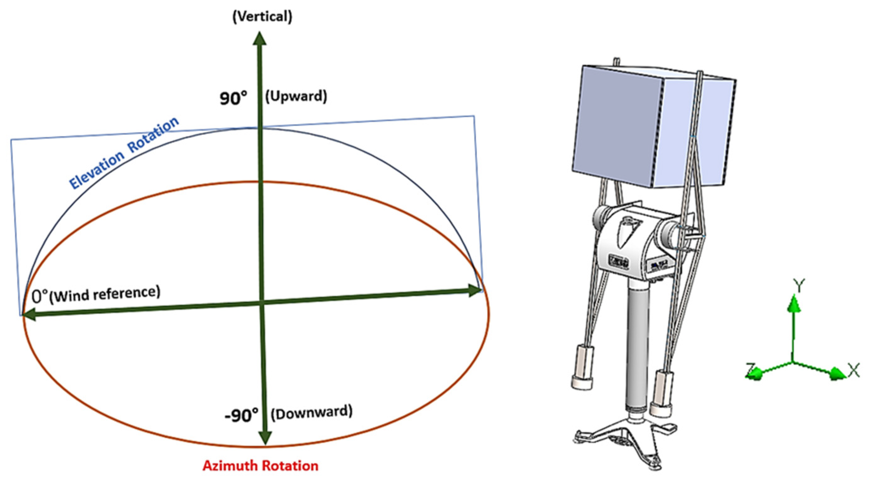
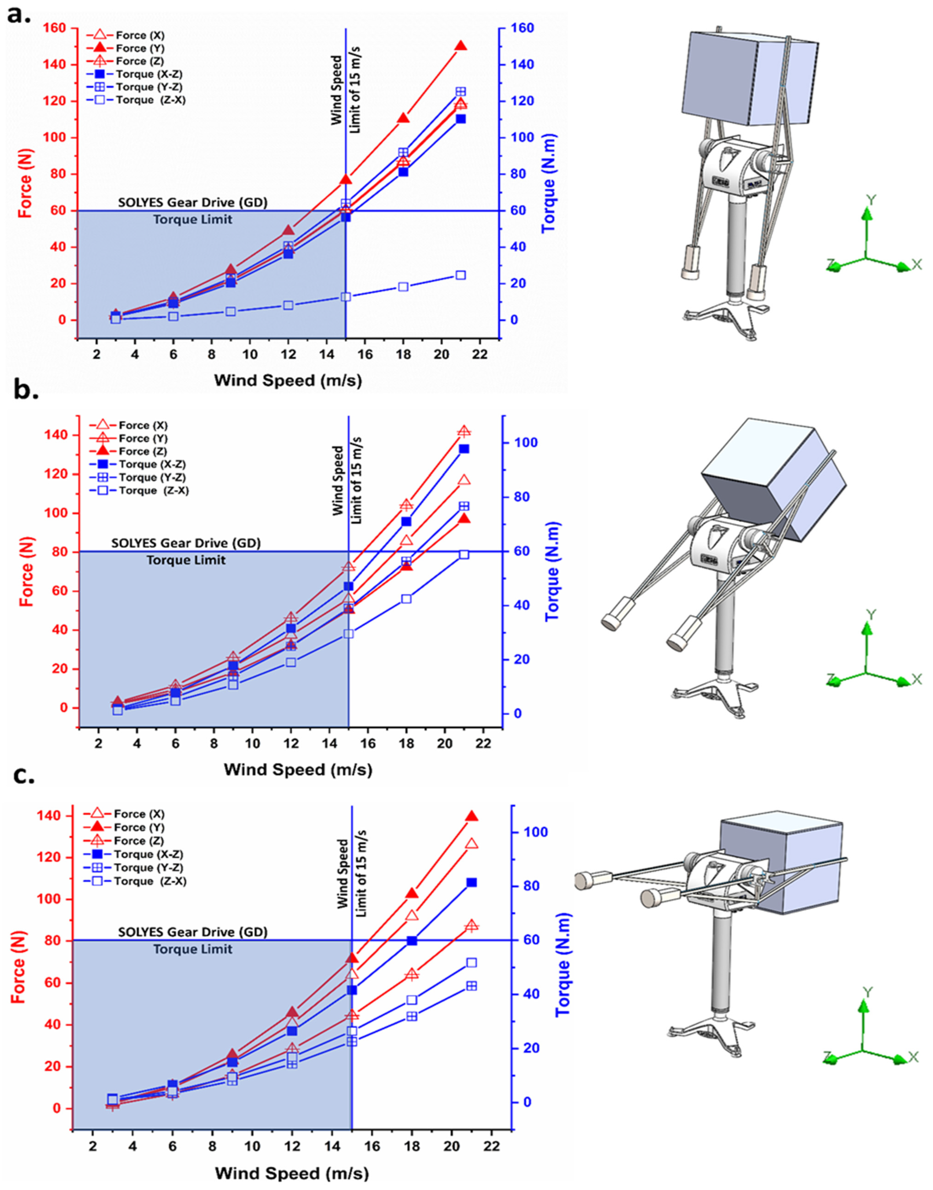
6.3. Impact of Wind Load

Wind load is a critical factor in ensuring that the system is not subjected to excessive or destabilizing forces. Wind-induced forces may cause system overturning or generate torque levels exceeding the sun tracker’s rated capacity of 60 N·m. The system is mechanically anchored to a fixed base, eliminating the risk of overturning under normal operating conditions. However, torque generation must be evaluated across all axes (x, y, and z) and at various orientation angles. According to World Weather Online, peak wind speeds at Penryn Campus have reached up to 54 km/h (15 m/s), which serves as a reference point for simulation limits. Torque values were analyzed for all axes, and the operational limit was determined by the first constraint reached—either the sun tracker’s torque capacity or the local maximum wind speed. To simulate a worst-case aerodynamic profile, the HCPV system was modeled as a solid block, ensuring that all operating conditions remain within safety margins.
A 3D flow simulation was conducted to evaluate wind effects on the full system assembly. The CFD simulation was conducted using SOLIDWORKS Flow Simulation, with a primary focus on evaluating the maximum wind-induced torque and drag force to ensure alignment stability and structural integrity under extreme conditions. The mesh was generated using a Cartesian mesh with local refinement in high-gradient regions. The default turbulence model (k–ε) was used, which is suitable for external flow around bluff bodies.
The wind load analysis considers two key orientation parameters of the assembly:
  • Azimuth angle (0–360°): This angle represents the horizontal orientation of the assembly relative to the wind direction. An azimuth of 0° means the wind strikes the front face directly, 90° strikes the side, 180° the rear, and 270° the opposite side.
  • Elevation angle (−90° to +90°): This angle represents the vertical tilt of the assembly relative to the ground. An elevation of 0° indicates a horizontal (flat) position, +90° is vertical facing upward, and −90° is vertical facing downward.
These angles are illustrated in Figure 13, and all wind load simulations were performed by varying both angles to represent different possible wind exposure conditions.
Wind speed was applied from a minimum value of 3 m/s to an extreme level of 22 m/s (this level is characterized as a tropical storm) with an interval of 3 m/s. Torque direction was determined using the right-hand rule: force in the x-direction induces torque about the z-axis; force in the y-direction also generates torque about the z-axis; and force in the z-direction results in torque about the x-axis. Figure 14a–c presents the simulation results for system orientations at 80° (counter-clockwise), 35° (counter-clockwise), and −5° (clockwise), respectively. Each plot includes reference lines for the sun tracker torque limit and the maximum allowable wind speed, with the shaded region indicating safe outdoor operating conditions. Although this analysis is essential for temporary outdoor deployment, the experimental setup will be operated exclusively on clear, sunny days in compliance with the safety protocols at Penryn Campus, University of Exeter.

7. Conclusions

This study presented a comprehensive structural analysis and system integration of a modular high-concentration photovoltaic (HCPV) prototype, emphasizing its mechanical performance and readiness for experimental deployment. The system incorporates a reinforced beam structure capable of sustaining operational loads up to 10 kg on each side with a deformation limited to 0.1 mm, as confirmed through static analysis. Windage simulations under varying azimuth angles and wind speeds demonstrated the system’s stability, with torque values remaining below the sun tracker’s limit of 60 Nm at a maximum wind speed of 15 m/s, ensuring reliable outdoor operation. Additionally, the spatial layout and counterbalance system were optimized to ensure alignment and sun-tracking accuracy, with a required operating footprint of 2 m in diameter. These quantitative assessments validate the system’s robustness under realistic environmental and loading conditions. The modular optical assembly, compatible with various Fresnel lens configurations and heat sink geometries, allows for future scalability and testing flexibility. This work lays the groundwork for a second-generation prototype with a reduced height profile (from 55 cm to 35 cm), while retaining key structural and alignment features. Overall, the findings highlight a mechanically resilient and experimentally adaptable platform that advances the deployment readiness of HCPV systems.

Author Contributions

Conceptualization, T.M., M.A., W.C., K.S., T.K.M. and S.A.; methodology, T.M., M.A., W.C., K.S., S.E.A., T.K.M. and S.A.; software, T.M., M.A., W.C., K.S., T.K.M. and S.A.; validation, T.M., M.A., W.C., K.S., T.K.M. and S.A.; analysis, T.M., M.A., W.C., K.S., S.E.A., T.K.M. and S.A.; investigation, T.M., M.A., W.C., K.S., T.K.M. and S.A.; resources, T.M., M.A., W.C., K.S., T.K.M. and S.A.; data curation, T.M., M.A., W.C., K.S., S.E.A., T.K.M. and S.A.; writing—original draft preparation, T.M. and M.A.; writing—review and editing, T.M., M.A., W.C., K.S., S.E.A., T.K.M. and S.A.; visualization, T.M., M.A., W.C., K.S., S.E.A., T.K.M. and S.A.; supervision, T.M., M.A. and T.K.M.; project administration, T.M., M.A. and T.K.M.; funding acquisition, M.A. All authors have read and agreed to the published version of the manuscript.

Funding

This research received no external funding.

Data Availability Statement

Data are contained within the article.

Acknowledgments

The authors would like to acknowledge the support provided by Imam Abdulrahman Bin Faisal University (IAU), Dammam, Saudi Arabia.

Conflicts of Interest

The authors declare no conflict of interest.

References

  1. Shanks, K.; Senthilarasu, S.; Mallick, T.K. Optics for Concentrating Photovoltaics: Trends, Limits and Opportunities for Materials and Design. Renew. Sustain. Energy Rev. 2016, 60, 394–407. [Google Scholar] [CrossRef]
  2. Lovegrove, K.; Burgess, G.; Pye, J. A New 500 m 2 Paraboloidal Dish Solar Concentrator. Sol. Energy 2011, 85, 620–626. [Google Scholar] [CrossRef]
  3. Schmitz, M.; Wiik, N.; Ambrosetti, G.; Pedretti, A.; Paredes, S.; Ruch, P.; Michel, B.; Steinfeld, A. A 6-Focus High-Concentration Photovoltaic-Thermal Dish System. Sol. Energy 2017, 155, 445–463. [Google Scholar] [CrossRef]
  4. Ferrer-Rodríguez, J.P.; Saura, J.M.; Fernández, E.F.; Almonacid, F.; Talavera, D.L.; Pérez-Higueras, P. Exploring Ultra-High Concentrator Photovoltaic Cassegrain-Koehler-Based Designs up to 6000×. Opt Express 2020, 28, 6609. [Google Scholar] [CrossRef]
  5. Ferrer-Rodríguez, J.P.; Fernández, E.F.; Almonacid, F.; Pérez-Higueras, P. Optical Design of a 4-off-Axis-Unit Cassegrain Ultra-High Concentrator Photovoltaics Module with a Central Receiver. Opt. Lett. 2016, 41, 1985. [Google Scholar] [CrossRef]
  6. Jacob, J.; Pandey, A.K.; Abd Rahim, N.; Selvaraj, J.; Samykano, M.; Saidur, R.; Tyagi, V.V. Concentrated Photovoltaic Thermal (CPVT) Systems: Recent Advancements in Clean Energy Applications, Thermal Management and Storage. J. Energy Storage 2022, 45, 103369. [Google Scholar] [CrossRef]
  7. Khelifa, A.; Abdelgaied, M.; Harby, K.; Attia, M.E.H. Performance Improvement of Photovoltaic/Thermal Collectors Based on the Optimized Design of Efficient Innovative Multiple-Impinging Slot Jets. Sol. Energy 2024, 283, 112992. [Google Scholar] [CrossRef]
  8. Iqbal, W.; Ullah, I.; Shin, S. Optical Developments in Concentrator Photovoltaic Systems—A Review. Sustainability 2023, 15, 10554. [Google Scholar] [CrossRef]
  9. Ceballos, M.A.; Pérez-Higueras, P.J.; Fernández, E.F.; Almonacid, F. Tracking-Integrated CPV Technology: State-of-the-Art and Classification. Energies 2023, 16, 5605. [Google Scholar] [CrossRef]
  10. Abo-Zahhad, E.M.; Haridy, S.; Radwan, A.; El-Sharkawy, I.I.; Esmail, M.F.C. Thermal Management of Ultra High Concentrator Photovoltaic Cells: Analysing the Impact of Sintered Porous Media Microchannel Heat Sinks. J. Clean. Prod. 2024, 465, 142649. [Google Scholar] [CrossRef]
  11. Tang, J.; Li, X.; Hu, R.; Mo, Z.; Du, M. A Novel Designed Manifold Ultrathin Micro Pin-Fin Channel for Thermal Management of High-Concentrator Photovoltaic System. Int. J. Heat. Mass. Transf. 2022, 183, 122094. [Google Scholar] [CrossRef]
  12. Elqady, H.I.; Radwan, A.; Ali, A.Y.M.; Rabie, M.; Abo-Zahhad, E.M.; Ookawara, S.; Elkady, M.F.; El-Shazly, A.H. Concentrator Photovoltaic Thermal Management Using a New Design of Double-Layer Microchannel Heat Sink. Sol. Energy 2021, 220, 552–570. [Google Scholar] [CrossRef]
  13. Tan, W.-C.; Chong, K.-K.; Tan, M.-H. Performance Study of Water-Cooled Multiple-Channel Heat Sinks in the Application of Ultra-High Concentrator Photovoltaic System. Sol. Energy 2017, 147, 314–327. [Google Scholar] [CrossRef]
  14. Sajid, M.U.; Abedrabboh, O.; Bicer, Y. Performance Evaluation of Interrupted and Hybrid Channel Heat Sinks for a Triple Junction High Concentrator Photovoltaic Cell. Int. J. Thermofluids 2025, 26, 101102. [Google Scholar] [CrossRef]
  15. Valera, Á.; Rodrigo, P.M.; Ceballos, M.A.; Almonacid, F.; Fernández, E.F. Design, Manufacturing and Indoor/Outdoor Testing of a Hybrid Thermoelectric-Concentrator Photovoltaic Mono-Module at Unprecedented Ultra-High Concentration Levels. Sol. Energy Mater. Sol. Cells 2023, 254, 112269. [Google Scholar] [CrossRef]
  16. Micheli, L.; Sarmah, N.; Luo, X.; Reddy, K.S.; Mallick, T.K. Design and Production of a 2.5 KWe Insulated Metal Substrate-Based Densely Packed CPV Assembly. In Proceedings of the AIP Conference Proceedings, New Orleans, LA, USA, 26 September 2014; American Institute of Physics Inc.: Washington, DC, USA, 2014; Volume 1616, pp. 196–199. [Google Scholar]
  17. Awasthi, A.; Kumar, A.; SR, M.M.; Dondariya, C.; Shukla, K.N.; Porwal, D.; Richhariya, G. Review on Sun Tracking Technology in Solar PV System. Energy Rep. 2020, 6, 392–405. [Google Scholar] [CrossRef]
  18. Singh, R.; Kumar, S.; Gehlot, A.; Pachauri, R. An Imperative Role of Sun Trackers in Photovoltaic Technology: A Review. Renew. Sustain. Energy Rev. 2018, 82, 3263–3278. [Google Scholar] [CrossRef]
  19. Orynbassar, S.; Almen, D.; Mekhilef, S.; Kapparova, A.; Dosymbetova, G.; Nurgaliyev, M.; Saymbetov, A.; Ibraimov, M.; Kuttybay, N.; Yershov, E. Minimum Solar Tracking System for a Fresnel Lens-Based LCPV. Renew. Energy 2024, 237, 121607. [Google Scholar] [CrossRef]
  20. Paliyal, P.S.; Mondal, S.; Layek, S.; Kuchhal, P.; Pandey, J.K. Automatic Solar Tracking System: A Review Pertaining to Advancements and Challenges in the Current Scenario. Clean. Energy 2024, 8, 237–262. [Google Scholar] [CrossRef]
  21. Kuttybay, N.; Mekhilef, S.; Koshkarbay, N.; Saymbetov, A.; Nurgaliyev, M.; Dosymbetova, G.; Orynbassar, S.; Yershov, E.; Kapparova, A.; Zholamanov, B. Assessment of Solar Tracking Systems: A Comprehensive Review. Sustain. Energy Technol. Assess. 2024, 68, 103879. [Google Scholar] [CrossRef]
  22. Maka, A.O.M.; O’Donovan, T.S. A Review of Thermal Load and Performance Characterisation of a High Concentrating Photovoltaic (HCPV) Solar Receiver Assembly. Sol. Energy 2020, 206, 35–51. [Google Scholar] [CrossRef]
  23. Ceballos, M.A.; Fernández, E.F.; Rodrigo, P.M.; Valera, Á.; Pérez-Higueras, P.J.; Almonacid, F. High-Performance 4096× Ultra-High CPV Module Based on Multiple Concentrator Units and Optical Guides. Opt. Lett. 2021, 46, 4188–4191. [Google Scholar] [CrossRef] [PubMed]
  24. Alzahrani, M.; Ahmed, A.; Shanks, K.; Sundaram, S.; Mallick, T. Optical Component Analysis for Ultrahigh Concentrated Photovoltaic System (UHCPV). Sol. Energy 2021, 227, 321–333. [Google Scholar] [CrossRef]
  25. Alzahrani, M.M.; Shanks, K.; Chanchangi, Y.; Cameron, W.J.; Maatallah, T.S.; Mallick, T.K. Record High Solar Concentration Ratio for Photovoltaics: Experimental Validation for Achieving Effective Concentration of >1200 Suns. Sol. Energy 2024, 271, 112427. [Google Scholar] [CrossRef]
  26. Cameron, W.J.; Alzahrani, M.M.; Yule, J.; Shanks, K.; Reddy, K.S.; Mallick, T.K. Indoor Experimental Analysis of Serpentine-Based Cooling Scheme for High Concentration Photovoltaic Thermal Systems. Appl. Therm. Eng. 2023, 234, 121183. [Google Scholar] [CrossRef]
  27. Cameron, W.J.; Alzahrani, M.; Shanks, K.; Mallick, T.K.; Reddy, K.S. Optical Losses and Durability of 4-Domed Optic for Concentrator Photovoltaics; University of Exeter: Exeter, UK, 2022. [Google Scholar]
  28. Yang, S.-Y.; Leng, Y.-K.; Cheng, Z.-D.; Wang, W.-Q.; He, Y.-L. Optical-Thermal–Mechanical Comprehensive Performance of the Concentrating and Collecting Subsystem for the next-Generation Solar Power Tower Based on Heliostat Field Layouts Optimization. Sol. Energy 2024, 275, 112604. [Google Scholar] [CrossRef]
  29. Cappelletti, A.; Nelli, L.C.; Reatti, A. Integration and Architectural Issues of a Photovoltaic/Thermal Linear Solar Concentrator. Sol. Energy 2018, 169, 362–373. [Google Scholar] [CrossRef]
  30. KJN. Aluminium Profile. Available online: https://www.aluminium-profile.co.uk/ (accessed on 18 February 2025).
  31. Laser Cutting Subcontractor-Southern England & Wales-Laser Industries. Available online: https://www.laser.co.uk/ (accessed on 18 February 2025).
  32. Industrial Solutions & Electrical Components|RS. Available online: https://uk.rs-online.com/web/ (accessed on 18 February 2025).
  33. ORAFOL. Fresnel Optics GmbH. Available online: https://www.orafol.com/en/ (accessed on 10 March 2022).
  34. Cornwall Glass Comapny_Penryn. Available online: https://cornwallglass.co.uk/your-branch/penryn/ (accessed on 10 March 2022).
  35. Kipp & ZONEN. Instruction Manual: SOLYS2 & SOLYS Gear Drive; Kipp & ZONEN: Delft, The Netherlands, 2003. [Google Scholar]
  36. Kipp & ZONEN. Available online: https://www.kippzonen.com/ (accessed on 11 April 2021).
Figure 1. Structural configuration of the modular HCPV system: (a) asymmetric view of the system model, (b) top view of the system model, (c) actual prototype during assembly (asymmetric view), and (d) side view of the assembled system.
Machines 13 00468 g001
Figure 2. Ray trajectories.
Machines 13 00468 g002
Figure 3. Optical setup and optimum adjustment of the optics position based on numerical analysis.
Machines 13 00468 g003
Figure 4. Experimental configuration of one-quarter of the HCPV system: (a) secondary mirror frame assembly, (b) thumb nut vertical adjuster, (c) fully assembled secondary mirror stage, (d) CAD model of ¼ of the system, and (e) yaw rotation axis of the secondary mirror frame.
Machines 13 00468 g004
Figure 5. Adjustment features of the third-stage reflector for ¼ of the HCPV system: (a) vertical motion range, (b) lateral translation (latitude and longitude), (c) roll control, (d) pitch tuning, and (e) actual mirror-mounted third-stage configuration.
Machines 13 00468 g005
Figure 6. Receiver stage of the HCPV system: (a) vertical motion capability, (b) latitude and longitude translations, (c) actual receiver base photo, (d) thermal protection shield, and (e) integrated receiver configuration within the full HCPV prototype.
Machines 13 00468 g006
Figure 7. (a) SOLYS2 sun tracker with tripod setup; (b) top view of the recommended heavy-duty floor stand [35].
Machines 13 00468 g007
Figure 8. Beam analysis of interlink mechanical structure: (a) beam geometry and boundary setup; (b) stress distribution under static load; (c) resulting deformation profile.
Machines 13 00468 g008
Figure 9. The stress, force, and deformation at the applied masses. The crossline shows the values at the actual applied system mass and counterbalance of 6.5 kg/each side.
Machines 13 00468 g009
Figure 10. Reinforced interlink beam configuration: (a) updated triangular geometry with added diagonal support; (b) stress distribution under static loading; (c) deformation contours showing reduced deflection.
Machines 13 00468 g010
Figure 11. The stress, force, and deformation at the applied masses for the reinforced interlink beam. The crossline shows the values at the actual applied system mass and counterbalance of 6.5 kg/each side.
Machines 13 00468 g011
Figure 12. The integration of the counterbalance arm, counterbalance weight, and HCPV system to the sun tracker, where (a) is the 3D model of the full system assembly and (b) is the full actual system, outdoor and ready for testing.
Machines 13 00468 g012
Figure 13. Definitions of azimuth and elevation angles used in wind load analysis.
Machines 13 00468 g013
Figure 14. Shows the applied wind speed and the resulting force and torque values for the complete setup at an oriented angle, where (a) is sited at 80° CCW, (b) is sited at 35° CCW, and (c) is sited at −5° CW.
Machines 13 00468 g014
Table 1. Comparative analysis of different optical stages of the system.
Optical StageOptical Efficiency (%)
Fresnel lens91.11
Fresnel lens + secondary stage optic73.33
Fresnel lens + secondary stage optic + tertiary optic59.07
Table 2. The sun trackers’ specifications comparison [36].
Sun Tracker ModelSOLYS2SOLYS Gear Drive (GD)
Pointing/tracking accuracy<0.1° (passive)
<0.02° (active)
<0.1° (passive)
<0.02° (active)
Torque20 Nm60 Nm
Payload (counterbalance)20 kg80 kg
System weight28 kg (sun tracker with tripod)26 kg (only sun tracker)
TripodIncludedNot included (tripod of SOLYS2 can be used with a limit (no more than 50 kg))
Transmission systemInverted tooth beltsHigh-precision reduction gear
Disclaimer/Publisher’s Note: The statements, opinions and data contained in all publications are solely those of the individual author(s) and contributor(s) and not of MDPI and/or the editor(s). MDPI and/or the editor(s) disclaim responsibility for any injury to people or property resulting from any ideas, methods, instructions or products referred to in the content.

