Article

Digital Twins for Defect Detection in FDM 3D Printing Process

1
Key Laboratory of Bionic Engineering, Ministry of Education, Jilin University, Changchun 130025, China
2
Institute of Structured and Architected Materials, Liaoning Academy of Materials, Shenyang 110167, China
3
Weihai Institute for Bionics, Jilin University, Weihai 264207, China
4
College of Construction Engineering, Jilin University, Changchun 130025, China
*
Authors to whom correspondence should be addressed.
Machines 2025, 13(6), 448; https://doi.org/10.3390/machines13060448
Submission received: 8 April 2025 / Revised: 10 May 2025 / Accepted: 20 May 2025 / Published: 23 May 2025
(This article belongs to the Section Advanced Manufacturing)

Abstract

Additive manufacturing (AM, also known as 3D printing) is a bottom–up process where variations in process conditions can significantly influence the quality and performance of the printed parts. Digital twin (DT) technology can measure process parameters and printed part characteristics in real-time, achieving online monitoring, analysis, and optimization of the AM process. Existing DT research on AM focuses on simulating the printing process and lacks real-time defect detection and twinning of actual printed objects, which hinders the timely detection and correction of defects. This study developed a DT system for fused deposition modeling (FDM) AM technology that not only accurately simulates the printing process but also performs real-time quality monitoring of the printed parts. A laser profilometer and industrial camera were integrated into the printer to detect and collect real-time morphological data on the printed object. The custom-developed DT software could convert the morphological data of the printed parts into a DT model. By comparing the DT model of the printed object with its three-dimensional model, defect detection of the printed parts was achieved, where the quality of the printed parts was evaluated using a defect percentage index. This study combines DT and AM to achieve process quality monitoring, demonstrating the potential of DT technology in reducing printing defects and improving the quality of printed parts.

1. Introduction

Three-dimensional printing, or additive manufacturing (AM), can fabricate complex structures that are difficult to achieve with traditional manufacturing techniques, making it a disruptive manufacturing technology [1,2,3,4]. However, AM is susceptible to process variables which can cause defects or even the rejection of printed parts, leading to wasted time, energy, and materials [5,6,7]. These defects may arise from inappropriate process parameter settings [8,9,10], equipment aging, material quality, or environmental conditions such as temperature, humidity, vibration, or power supply [11,12,13]. Traditional post-processing analysis techniques struggle to detect and correct these defects promptly, often resulting in part rejection [14,15,16]. To mitigate errors during the printing process, it is necessary to monitor the AM process, promptly identify printing errors, and adjust process parameters and conditions accordingly [17,18,19,20].
Digital twin (DT) technology utilizes sensor data to conduct multi-physics and multi-scale simulations of physical objects, creating synchronized virtual digital twins. These digital twins can replicate physical processes in real-time and interact with them, enabling real-time monitoring, analysis, and optimization of the physical objects [21,22,23,24]. Both AM and DT are emerging technologies, and DT can help AM improve print quality and efficiency through process simulation, monitoring, and control optimization [25,26,27,28]. Combining DT and AM, an AMDT system can be established to perform real-time mapping between 3D-printed entities in the real world and virtual entities in the DT space, thus achieving the goal of online monitoring [29,30,31,32]. In the future, experiments will be conducted through industrial cameras using deep learning, employing the printed surface images in combination with the feedback mechanism to achieve a closed-loop digital twin system, which provides a smarter solution for additive manufacturing. Furthermore, combining AMDT with machine learning (ML) and artificial intelligence (AI) can elucidate the relationship between process variables and the quality of the printed part, leading to the rapid acquisition of optimized printing parameters.
Li et al. combined augmented reality with DT technology to achieve the DT of material extrusion 3D printing. They utilized a method called VACCY, which approximates the geometry of printed objects using cumulative small cylinders to create a digital representation of the printing process. The feasibility and performance of this approach were validated through augmented reality-based DT tests using four economic and environmental indicators [33]. Minas et al. proposed a DT ecosystem for AM created using a real-time development platform, consisting of data acquisition–processing–distribution components and virtual representation components. This ecosystem enabled real-time synchronization between physical machines and their digital counterparts, facilitating process monitoring, testing, and remote management [34]. Fabio et al. introduced a DT system for material extrusion 3D printers, comprising three main modules: a DT core, an interface for managing incoming data, and a graphical interface supporting remote user control. This system was tested on a custom 3D printer, collecting sensor data on the printer’s actual operations and comparing it with the virtual model, thus enabling real-time monitoring of the printing process either automatically or manually via the graphical interface [35]. Current research predominantly focuses on the digital mirroring of printing scenarios, without considering the actual state of the printed objects. However, real printed parts are prone to defects, and the lack of real-time detection of the printed objects prevents the timely identification and correction of printing defects. Therefore, the real-time detection of printed object characteristics and the generation of digital twins during printing are critical issues that need to be addressed preferentially. Machine learning (ML) is a very effective method for detecting and correcting printing defects in real time. Roach et al. proposed a real-time optimization method based on a reversible neural network and computer vision, which achieved fast and dynamic tuning of the extrusion additive manufacturing process by synchronously monitoring the print linewidth and solving the optimal parameters in reverse. The method breaks through the time bottleneck of the traditional trial-and-error method, provides a new paradigm of autonomous optimization for complex material printing, and promotes the development of the intelligent additive manufacturing system in the direction of high efficiency and precision [36].
In this study, we propose a novel DT framework tailored for fused deposition modeling (FDM) 3D printing. In contrast to existing DT research that focuses mainly on process simulation or offline inspection, this study aims to enable in-process quality monitoring, thus laying the foundation for the closed-loop control of intelligent AM systems. Focusing on real-time surface defect detection, and based on the fusion of point cloud and optical images, we achieved a real-time defect detection methodology that accurately classifies and quantifies over-extrusion and under-extrusion defects during the printing process, developed a modular DT architecture that integrates Unity3D and a Qt-based graphical user interface for simultaneous simulation, monitoring, and visualization of the printing process, and introduce a “defect percentage” metric derived from surface point cloud data to provide a quantitative metric for defect assessment. In addition, we built customized experimental platforms integrating laser profilers and industrial cameras to support multimodal data acquisition for high-resolution morphological analysis.

2. Materials and Methods

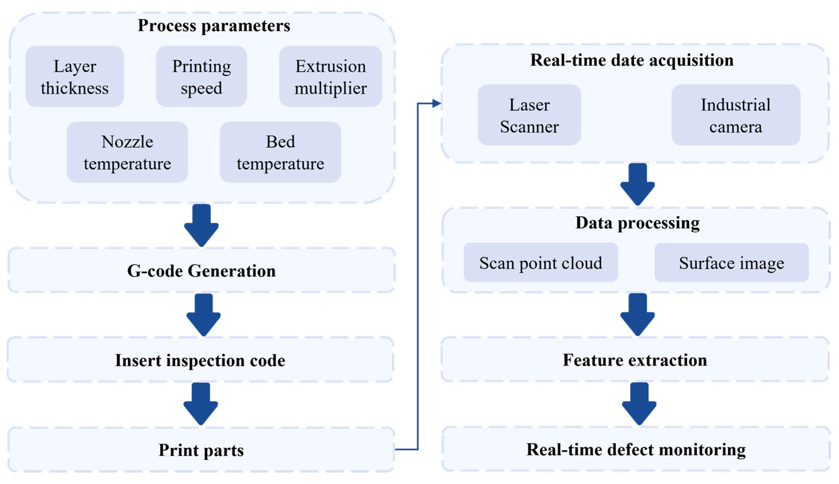
2.1. Research Methodology

The proposed framework for the DT of the AM system, as illustrated in Figure 1, comprises physical entities, a virtual environment, digital data, applications, and the data exchange among them. The physical entities mainly include an FDM 3D printer, various built-in sensors of the printer, an industrial camera, and a laser profilometer. The virtual environment encompasses a synchronized virtual model of the printing process and a digital counterpart of the 3D printer, as well as the physical attributes, constraint properties, and motion logic assigned to the printer. The digital data consist of information obtained by various sensors during the 3D printing process, including position coordinates provided by encoders in the servo motors, speed, acceleration, and temperature data from the built-in sensors, image data captured by the industrial camera, and point cloud data obtained by the laser profilometer. The applications refer to the main functionalities of the AMDT, such as the real-time monitoring of operational status, simulation of the printing process, and real-time quality monitoring of printed parts. Data exchange involves real-time mapping between physical and virtual environments, data interactions between digital data and the physical environment, virtual environment, and applications, and the iterative optimization of physical and virtual environments by the applications.
Figure 2 illustrates the workflow of the defect detection study on the AMDT presented in this paper. Initially, different process parameter combinations are configured to generate the G-code program for printing parts. The G-code program is then modified to insert inspection codes to be executed between layers, creating the path planning that controls the 3D printer’s movements. Next, the workpiece is printed, and data acquired from the laser profilometer and industrial camera are processed. Finally, the extracted features from photographs and profiles of the prints are analyzed within regions of interest, enabling real-time defect monitoring.

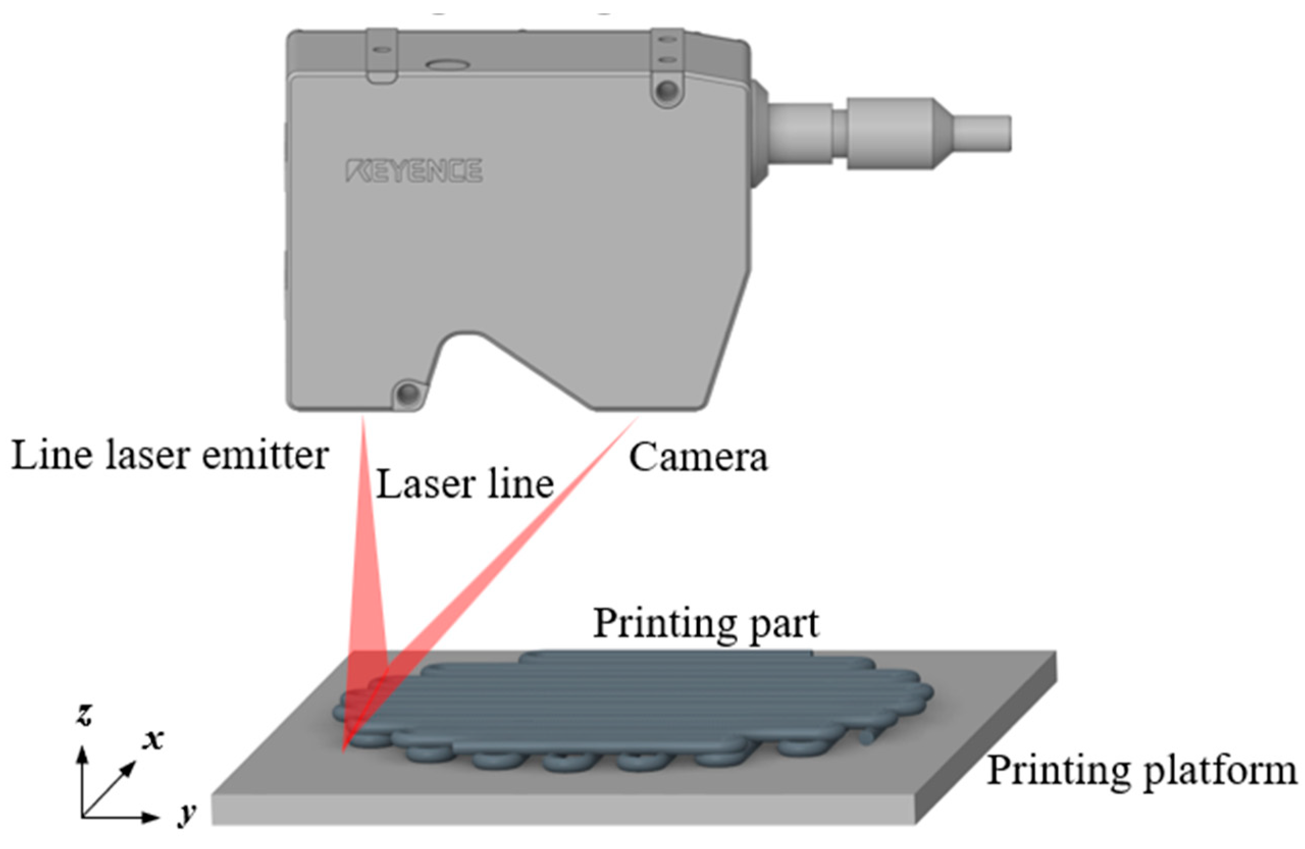
2.2. Data Processing

As shown in Figure 3, this study utilizes a line laser high-speed profilometer (LJ-V7060, KEYENCE (China) Co., Ltd., China, Shanghai) to acquire point cloud data on the printed part surfaces. The profilometer consists of a line laser emitter and a receiver, with a resolution of 0.4 μm in the Z direction and 5 μm in the X direction. By integrating the profilometer into the AM system, the printer drives the profilometer to scan the printed surface after each layer is deposited, obtaining the point cloud data of the current printing layer.
The raw data obtained by the laser profilometer are an m × n two-dimensional depth matrix, as shown in Figure 4a. By adding x and y coordinates according to the scan point spacing and the encoder frequency, the processed data can be converted into point cloud data. The point cloud data are then processed using a custom program based on the Open3D point cloud library in Python 3.11.11.
During the point cloud data acquisition process, various external factors such as environmental conditions, equipment precision, and machine vibrations can introduce noise or outliers that do not represent the actual surface morphology of the printed object. If these noise points are not removed, they may interfere with subsequent work. In this paper, a statistical filtering algorithm [37] is used to denoise the point cloud data. By adjusting the neighborhood size or the multiplication factor of the average distance and standard deviation, the intensity of the noise reduction can be controlled, thus finding a balance between noise removal and data detail retention. Figure 4b presents the measurement point cloud with noise points, highlighting the noise points concentrated in the step area. Figure 4c displays the point cloud processed with the statistical filtering algorithm. It can be seen that the noise in the point cloud has been effectively removed after filtering. Moreover, in Figure 4c, to better display the point cloud processed using the statistical outlier removal algorithm, points at different heights are rendered in different colors. When scanning, the laser scanner captures not only the printed parts but also the print substrate. Therefore, for the streamlined and denoised point cloud data, point cloud segmentation must be performed to extract the surface point cloud of the printed part. The random sample consensus (RANSAC) algorithm [38] is used to segment the plane of the point cloud and extract the upper surface point cloud of the printed part. Figure 4d shows the upper surface point cloud of the printed part extracted with the RANSAC algorithm.
During defect monitoring, the industrial camera captures images that include the print substrate, which are then cropped to obtain the region of interest, reducing the image size and shortening the processing time. A macro was written in ImageJ 1.8.0 to automatically crop the images acquired by the industrial camera. Subsequently, background removal is performed on the cropped images, followed by image processing to enhance brightness and contrast.

2.3. Parameter Settings

In this study, different printing settings were used to print small cubic test samples with dimensions of 12.4 × 12.4 × 3 mm. The fixed process parameters are listed in Table 1, and the variable process parameters are listed in Table 2. The slicing software Simplify3D was used to slice the STL model according to different process parameters, and the layer-change script function of Simplify3D was employed to edit monitoring scripts. The G-code for the test samples was then generated to control printing. After each layer is printed, the laser profile scanner scans the surface to obtain point cloud data for that layer. Subsequently, the surface is photographed to capture the image of the layer.

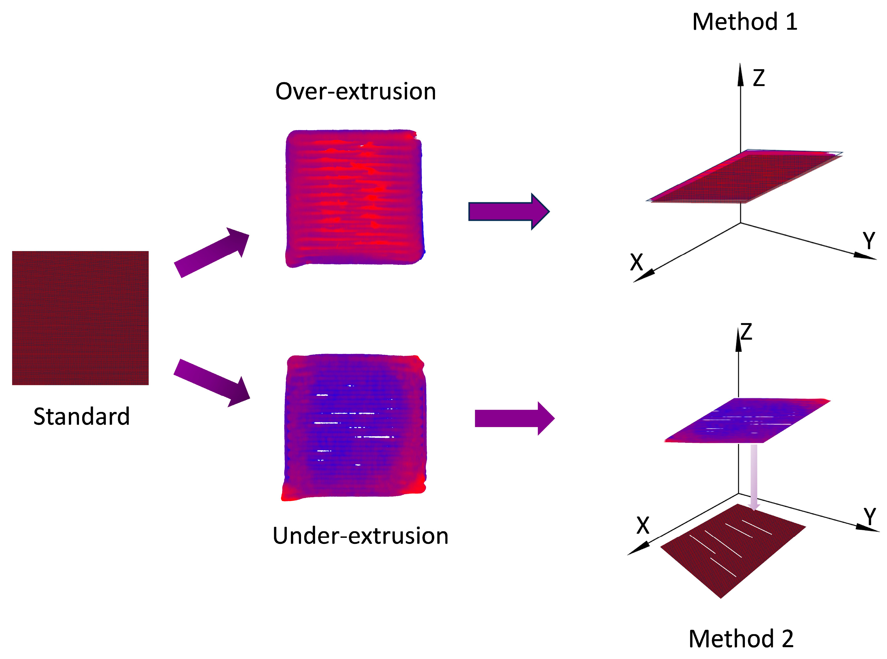
2.4. Defect Detection and Defect Portion Quantification

To evaluate the defects in the point cloud, a defect percentage indicator ( D P i ) is established to quantify the defective portions of the printed parts. Figure 5 shows two methods for calculating the defect percentage. The first method, which is mainly used in the case of over-extrusion, involves isolating the defective portion from the point cloud data of each layer. The extent of the defect can be quantified by comparing the measured Z-values of each layer with the Z-values of the layer without defect. The defect value is obtained by subtracting the Z-value of the layer without defect from the measured Z-value of each layer, and the quality of the printed part is characterized by calculating the percentage of the defective portion. The second method for detecting under-extrusion involves subtracting the projection area of the ith layer’s point cloud onto the XY-plane from the projection area of all point clouds of the defect-free layers, thus obtaining the area of the defective portion. After the aforementioned processing, the data of the defective portion can be extracted. The defect percentage ( D P i ) can be calculated using the following formula:
D P i = A r e a _ d e f e c t i A r e a _ l a y e r i
where A r e a _ d e f e c t i represents the total area of the point cloud data of the defective portion projected onto the XY-plane, and A r e a _ l a y e r i represents the area of the polygon containing all point clouds of the ith layer projected onto the XY-plane.

3. Results and Discussion

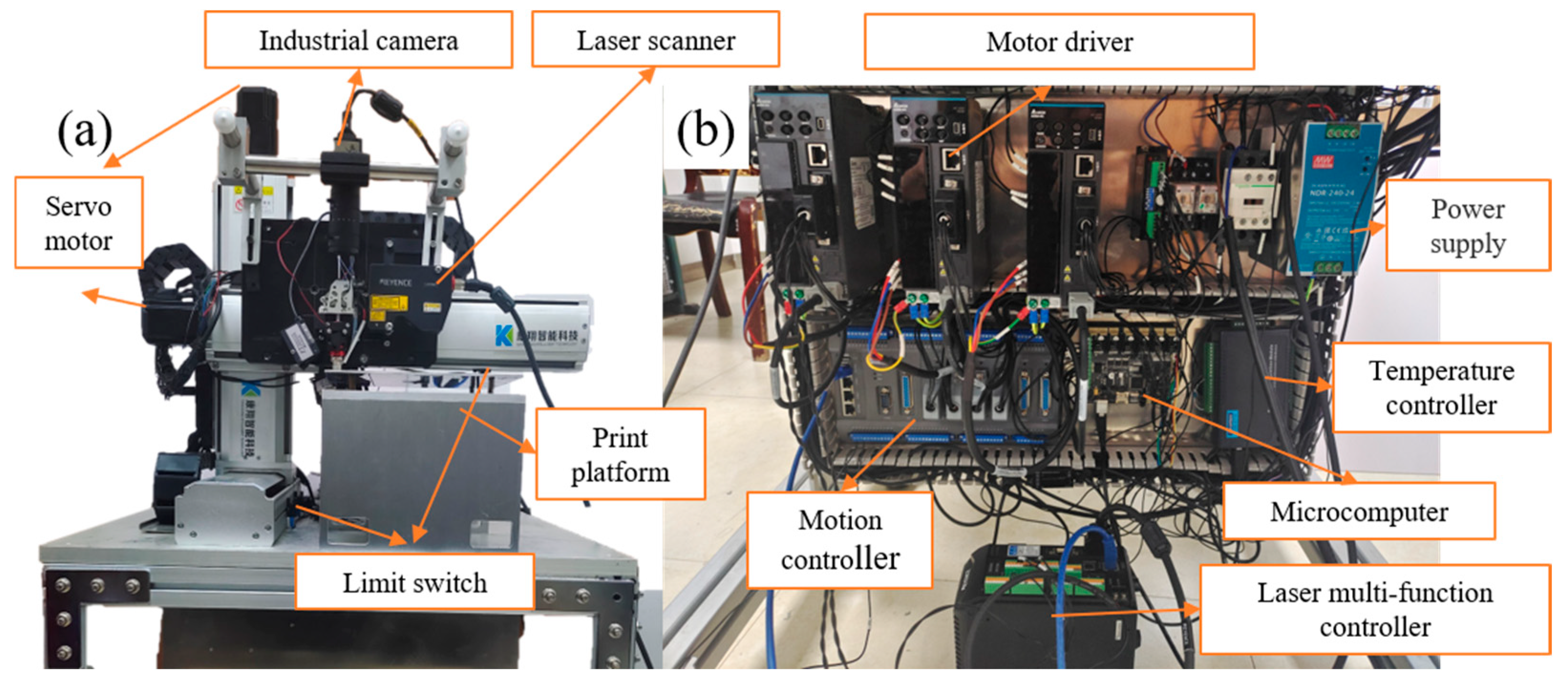
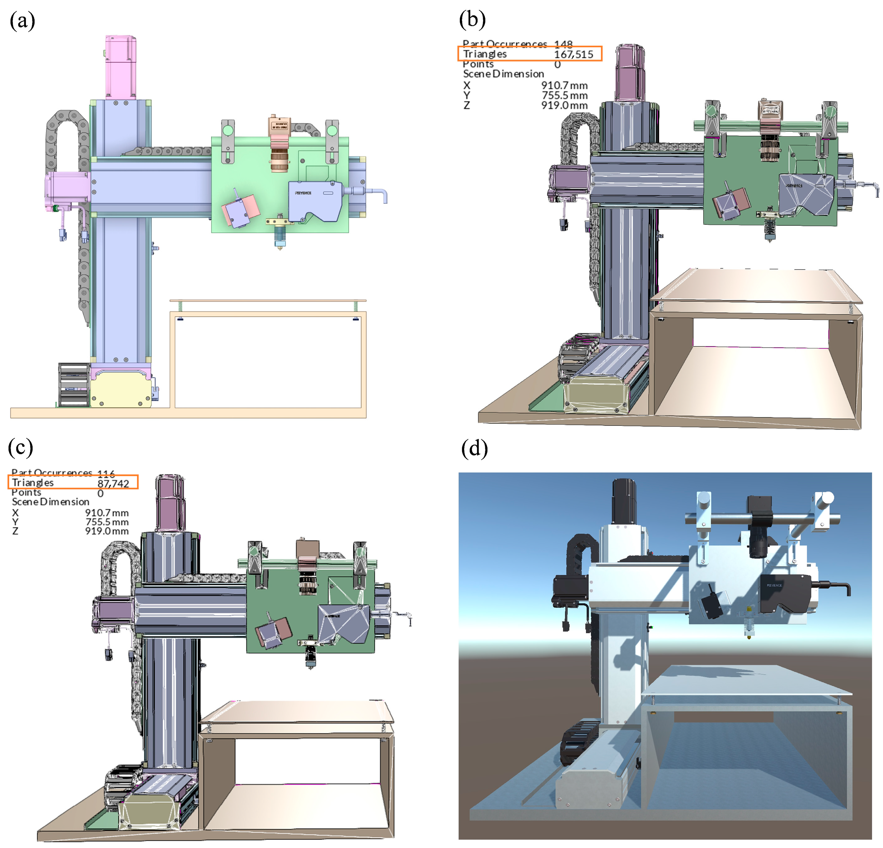
3.1. Experimental Apparatus

Figure 6 illustrates the FDM 3D printer and its components constructed for this study. To install sensors and achieve greater control over the 3D printer, a custom three-axis motion platform was developed for the physical construction of the 3D printer. The printer controller comprises a MEGATRONICS v3.0 motherboard burned with Marlin firmware. The servo motors, precisely controlled via encoder feedback, ensure high precision and repeatability without step loss. Both the X and Y axes are driven by servo motors through ball screws. To maintain load stability and prevent slippage, the Z axis employs a servo motor with a brake, also driven by a ball screw. The 3D printer is equipped with a high-speed laser profile scanner (KEYENCE LJ-V7060, KEYENCE (China) Co., Ltd., China, Shanghai) and an industrial camera (U-2220SE-C-HQ (IDS Imaging Development Systems GmbH, Obersulm, Germany)) to capture point cloud data and photographs of the printed part’s surface. The 3D printer has a build volume of 200 mm × 200 mm × 100 mm, which meets the experimental requirements.

3.2. The Digital Twin GUI

The first step in developing a DT for the 3D printer is to create its CAD model. In this study, Space Claim Direct Modeler (SCDM) was used for constructing the 3D printer model, as shown in Figure 7a. Since the format of the 3D model created by SCDM is not directly compatible with the real-time development platform, a format conversion is necessary. The detailed 3D model of the actual printer is very complicated, which may cause an excessive rendering load when imported into the real-time development platform. Therefore, to ensure the smooth operation of the AMDT, the model needs to be simplified. Pixyz Studio 2020 was selected for optimizing and converting the 3D printer model. Figure 7b,c shows the 3D printer model before and after the simplifying. The number of triangular facets was reduced from 167,000 to 87,000 after lightweight processing. Unity3D provides tools and platforms for creating, simulating, and visualizing virtual environments. In this study, Unity3D and the C# programming language were used to render the virtual model of the 3D printer, control its motion, develop experimental scenes, and monitor twin data. The optimized FBX (All major 3D data elements are supported) file exported from Pixyz was imported into Unity3D, and the parent–child hierarchy of the components was adjusted according to the actual situation to facilitate the addition of motion logic. To enhance the visual effects of the model and increase its realism and immersion, materials and textures were added to the model according to the actual appearance and morphology of the equipment. Figure 7d shows the 3D printer model rendered with materials and textures in Unity3D. Data transmission and communication between the 3D printer and Unity3D are carried out using a Socket communication protocol based on Transmission Control Protocol (TCP).
Figure 8a illustrates the application scenario of the 3D printer’s DT. The actual printer is shown in the upper left corner of Figure 8a. During the monitoring of its operational state, process parameters and control buttons are displayed on the screen’s right side. By monitoring the motion of both the physical and virtual 3D printers, the AMDT constructed in this study achieves precise synchronization between the physical and virtual 3D printers. Figure 8a shows the synchronized movement of the physical entities and the virtual 3D printer. After creating the virtual entity of the 3D printer in Unity3D, it can be exported as an .exe executable file. To simultaneously realize the functions of operational state monitoring, printing process simulation, and real-time quality monitoring, Qt5 and the C++ programming language were used to integrate the virtual entity created in Unity3D, the virtual entity of the printed surface obtained by the laser profile scanner, and the images captured by the industrial camera into a single printing control system. The control system software comprehensively controls the operation of the 3D printer, including the laser profile scanner, and the industrial camera, integrating functions such as STL model processing, print path generation, point cloud processing, printing process simulation, and operational state monitoring. Figure 8b shows the final integrated 3D printer control system interface. The control system software communicates with the 3D printer and the industrial camera via the Universal Serial Bus (USB) protocol. Communication between the control system software and the laser scanner is implemented using the Ethernet protocol to ensure high-frequency point cloud data transmission. With the control system software, the morphology of the printed surface can be monitored in real-time through point clouds and optical images. If a print quality issue is detected, corrective measures can be taken, such as resetting the system, removing the faulty print, and restarting the printing process.

3.3. Defect Detection

The surface quality of 3D-printed parts is classified into three types: normal printing, over-extrusion defects, and under-extrusion defects. Over-extrusion and under-extrusion defects are further categorized into mild, moderate, and severe levels. This study uses point cloud data obtained from a laser profile scanner to monitor and quantify these defects. In view of the fact that there is no standard for dividing the detection threshold for the degree of defects, we empirically present a method for classifying the thresholds, as shown in Table 3.
The defect quantification method is as follows: First, the defect percentage is calculated using the first method. If the percentage exceeds 1%, it is classified as an over-extrusion defect. A defect percentage between 1% and 5% indicates a mild over-extrusion defect, between 5% and 15% indicates a moderate over-extrusion defect, and above 15% indicates a severe over-extrusion defect. If the defect percentage is less than 1%, the second method is used to calculate the defect percentage. If it remains below 1%, the print is considered normal. If it exceeds 1%, it is classified as an under-extrusion defect. A defect percentage between 1% and 5% indicates a mild under-extrusion defect, between 5% and 15% indicates a moderate under-extrusion defect, and above 15% indicates a severe under-extrusion defect.
To verify the effectiveness of the proposed AMDT system, we fabricated test samples with both normal and defective prints using different combinations of process parameters. The defects were monitored and quantified based on the point cloud data obtained from the laser profile scanner. Table 4 lists the defect percentages and types in the samples prepared with different printing process parameters. As can be seen from the variation in the defect percentage shown in Figure 9, this system effectively monitors the quality of printed parts and distinguishes between different defects and their severity levels.
Figure 10 depicts the surface point cloud and optical images of normal and defective samples acquired by the control system software. The point cloud images reveal additional details that are not visible in the optical images, allowing for a more precise identification of the type and location of defects through the examination of point cloud distribution. Figure 10a shows the surface point cloud and optical images of a normally printed sample. Under normal conditions, the part is not only dimensionally accurate but also exhibits good surface roughness, with a defect percentage below 1%. Figure 10b presents the surface point cloud and optical images of a sample with excessive extrusion defects, along with their defect grade. Excessive extrusion defects arise from unreasonable printing parameter settings or machine malfunctions, causing the printer to extrude more material than expected. This results in excess material accumulation on the part’s surface, making it uneven and increasing surface roughness. Figure 10c illustrates the point cloud and optical images of the upper surface of a sample with under-extrusion defects, as well as the defect grade for under-extrusion. Similarly to excessive extrusion, under-extrusion defects are caused by improper printing parameters or machine faults, leading to insufficient material extrusion. Consequently, the printed part exhibits inter-layer gaps, rendering the overall structure incomplete and insufficiently strong. Insufficient material also results in a rough and uneven surface.

4. Discussion

Offline quality checks of printed parts in AM production often result in a waste of material, time, and energy. Printing errors often lead to quality degradation in the strength, geometric accuracy, and surface morphology of the printed part. While it is difficult to measure these metrics online, we can find clues to print errors, such as filament morphology and surface texture. This paper addresses the issue of manufacturing errors commonly encountered during the AM of printed parts by proposing the integration of DT with AM to digitally twin the physical entities of 3D printers and the surface morphology of printed parts. We have achieved the real-time acquisition of point clouds and images of the surface of the printed layer by DT technology and have established a method for defect evaluation. This study explores a new method for AM and print quality monitoring using DT, laying the foundation for the subsequent development of intelligent printing systems capable of performance prediction and real-time correction. The current work can detect defects in real time.
The ultimate goal of this research is to achieve twins of real printed objects, rather than idealized printed parts, to enable monitoring of the printing process. At this stage, we have only established a framework for twinning and a strategy for determining print defects. In the next step, we will introduce ML to determine the causes of defects and adjust the printing parameters in real time to correct the defects, as well as adopting certain printing strategies to reduce the probability of defects occurring. While most of the methods given in the literature so far focus on how to detect defects, we will next build a dataset using an industrial camera to capture images of the printing process and then incorporate a feedback mechanism to detect and correct the prints in real time during the printing process, therefore realizing a digital twin closed-loop printing system. At the same time, the point cloud data of the actual printed object obtained from the 3D scanner will be fed into the twin system built to enable remote monitoring of the object.
DT and ML, the core technologies of intelligent manufacturing, show revolutionary potential in AM. Combining DT with machine learning and artificial intelligence technologies opens up greater possibilities for AM, especially when it comes to reducing labor and material costs for complex prints and achieving greater intelligence. The synergy of the two gives the 3D printing system self-awareness and self-decision-making capabilities. This intelligent closed loop of virtual–real interaction transforms traditional trial-and-error manufacturing into data-driven precision manufacturing, providing reliable solutions for high-end fields such as personalized medical implants and aerospace engines, accelerating 3D printing from prototype manufacturing to industrial-grade mass production.

5. Conclusions

This study proposes a real-time monitoring system based on digital twin to achieve the online detection and quantification of over-extrusion and under-extrusion defects in the FDM 3D printing process. The conclusions are as follows.
  • The proposed DT system allows for the real-time acquisition of point cloud and image data during the printing process, enabling synchronized virtual–physical interaction through a Unity3D and Qt-based integrated system.
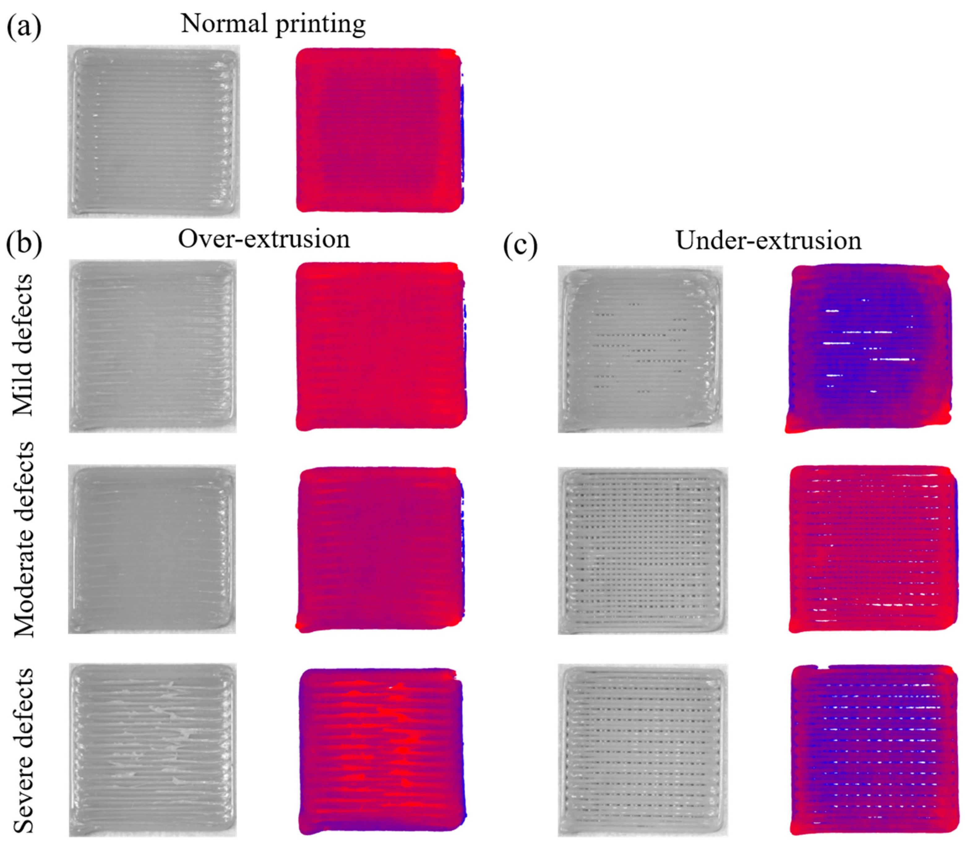
  • A “defect percentage” indicator based on point cloud analysis was developed to quantitatively assess surface defects, allowing for classification into over-extrusion and under-extrusion types with varying severity levels, providing a practical tool for real-time quality evaluation in AM.
  • Experimental validation shows that the system effectively detects and classifies defects during the printing process, reducing the reliance on offline inspection and laying the foundation for intelligent, self-correcting AM systems.

Author Contributions

Conceptualization, Q.L. and L.R.; methodology, H.L.; software, H.L.; validation, S.L. and Y.Z.; investigation, S.L.; resources, Z.S.; data curation, S.L. and Y.Z.; writing—original draft preparation, S.L. and L.Z.; writing—review and editing, C.X. and Z.S.; visualization, H.L.; supervision, Q.L. and L.R.; project administration, C.X.; funding acquisition, C.X. All authors have read and agreed to the published version of the manuscript.

Funding

This work is supported by National Natural Science Foundation of China, China (Grant ID: 52475298); National Key Research and Development Program of China, China (Grant ID: 2022YFB4600203), Young Elite Scientists Sponsorship Program by Jilin Association for Science and Technology, China (Grant ID: QT202323); Changchun Science and Technology Bureau (Grant ID: 23YQ13); Department of Science and Technology of Jilin Province, China (Grant ID: 20230402063GH); the 10th Youth Talent Support Program of the China Association for Science and Technology (CAST).

Data Availability Statement

Data will be made available on request.

Conflicts of Interest

The authors declare no conflicts of interest.

References

  1. du Plessis, A.; Razavi, N.; Benedetti, M.; Murchio, S.; Leary, M.; Watson, M.; Bhate, D.; Berto, F. Properties and applications of additively manufactured metallic cellular materials: A review. Prog. Mater. Sci. 2022, 125, 100918. [Google Scholar] [CrossRef]
  2. Tan, C.; Li, R.; Su, J.; Du, D.; Du, Y.; Attard, B.; Chew, Y.; Zhang, H.; Lavernia, E.J.; Fautrelle, Y.; et al. Review on field assisted metal additive manufacturing. Int. J. Mach. Tools Manuf. 2023, 189, 104032. [Google Scholar] [CrossRef]
  3. Hegab, H.; Khanna, N.; Monib, N.; Salem, A. Design for sustainable additive manufacturing: A review. Sustain. Mater. Technol. 2023, 35, e00576. [Google Scholar] [CrossRef]
  4. Cano-Vicent, A.; Tambuwala, M.M.; Hassan, S.S.; Barh, D.; Aljabali, A.A.; Birkett, M.; Arjunan, A.; Serrano-Aroca, Á. Fused deposition modelling: Current status, methodology, applications and future prospects. Addit. Manuf. 2021, 47, 102378. [Google Scholar] [CrossRef]
  5. Kim, H.; Lee, H.; Ahn, S.-H. Systematic deep transfer learning method based on a small image dataset for spaghetti-shape defect monitoring of fused deposition modeling. J. Manuf. Syst. 2022, 65, 439–451. [Google Scholar] [CrossRef]
  6. Brion, D.A.J.; Shen, M.; Pattinson, S.W. Automated recognition and correction of warp deformation in extrusion additive manufacturing. Addit. Manuf. 2022, 56, 102838. [Google Scholar] [CrossRef]
  7. Brion, D.A.J.; Pattinson, S.W. Quantitative and real-time control of 3D printing material flow through deep learning. Adv. Intell. Syst. 2022, 4, 2200153. [Google Scholar] [CrossRef]
  8. Brion, D.A.J.; Pattinson, S.W. Generalisable 3D printing error detection and correction via multi-head neural networks. Nat. Commun. 2022, 13, 4654. [Google Scholar] [CrossRef]
  9. Tan, L.; Huang, T.; Liu, J.; Li, Q.; Wu, X. Deep adversarial learning system for fault diagnosis in fused deposition modeling with imbalanced data. Comput. Ind. Eng. 2023, 176, 108887. [Google Scholar] [CrossRef]
  10. Fu, Y.; Downey, A.R.J.; Yuan, L.; Huang, H.-T. Real-time structural validation for material extrusion additive manufacturing. Addit. Manuf. 2023, 65, 103409. [Google Scholar] [CrossRef]
  11. AbouelNour, Y.; Gupta, N. In-situ monitoring of sub-surface and internal defects in additive manufacturing: A review. Mater. Des. 2022, 222, 111063. [Google Scholar] [CrossRef]
  12. Westphal, E.; Seitz, H. Machine learning for the intelligent analysis of 3D printing conditions using environmental sensor data to support quality assurance. Addit. Manuf. 2022, 50, 102535. [Google Scholar] [CrossRef]
  13. Wu, D.; Wei, Y.; Terpenny, J. Predictive modelling of surface roughness in fused deposition modelling using data fusion. Int. J. Prod. Res. 2018, 57, 3992–4006. [Google Scholar] [CrossRef]
  14. Liu, C.; Law, A.C.C.; Roberson, D.; Kong, Z. Image analysis-based closed loop quality control for additive manufacturing with fused filament fabrication. J. Manuf. Syst. 2019, 51, 75–86. [Google Scholar] [CrossRef]
  15. Gardner, J.M.; Hunt, K.A.; Ebel, A.B.; Rose, E.S.; Zylich, S.C.; Jensen, B.D.; Wise, K.E.; Siochi, E.J.; Sauti, G. Machines as craftsmen: Localized parameter setting optimization for fused filament fabrication 3D printing. Adv. Mater. Technol. 2019, 4, 1800653. [Google Scholar] [CrossRef]
  16. Lu, L.; Hou, J.; Yuan, S.; Yao, X.; Li, Y.; Zhu, J. Deep learning-assisted real-time defect detection and closed-loop adjustment for additive manufacturing of continuous fiber-reinforced polymer composites. Robot. Comput. Integr. Manuf. 2023, 79, 102431. [Google Scholar] [CrossRef]
  17. AbouelNour, Y.; Gupta, N. Assisted defect detection by in-process monitoring of additive manufacturing using optical imaging and infrared thermography. Addit. Manuf. 2023, 67, 103483. [Google Scholar] [CrossRef]
  18. Petsiuk, A.; Pearce, J.M. Towards smart monitored AM: Open source in-situ layer-wise 3D printing image anomaly detection using histograms of oriented gradients and a physics-based rendering engine. Addit. Manuf. 2022, 52, 102690. [Google Scholar] [CrossRef]
  19. Hossain, R.-E.N.; Lewis, J.; Moore, A.L. In situ infrared temperature sensing for real-time defect detection in additive manufacturing. Addit. Manuf. 2021, 47, 102328. [Google Scholar] [CrossRef]
  20. Lu, L.; Yuan, S.; Yao, X.; Li, Y.; Zhu, J.; Zhang, W. In-situ process evaluation for continuous fiber composite additive manufacturing using multisensing and correlation analysis. Addit. Manuf. 2023, 74, 103721. [Google Scholar] [CrossRef]
  21. Gunasegaram, D.R.; Murphy, A.B.; Barnard, A.; DebRoy, T.; Matthews, M.J.; Ladani, L.; Gu, D. Towards developing multiscale-multiphysics models and their surrogates for digital twins of metal additive manufacturing. Addit. Manuf. 2021, 46, 102089. [Google Scholar] [CrossRef]
  22. Su, S.; Nassehi, A.; Hicks, B.; Ross, J. Characterisation and evaluation of identicality for digital twins for the manufacturing domain. J. Manuf. Syst. 2023, 71, 224–237. [Google Scholar] [CrossRef]
  23. Leng, J.; Wang, D.; Shen, W.; Li, X.; Liu, Q.; Chen, X. Digital twins-based smart manufacturing system design in Industry 4.0: A review. J. Manuf. Syst. 2021, 60, 119–137. [Google Scholar] [CrossRef]
  24. Liu, X.; Jiang, D.; Tao, B.; Jiang, G.; Sun, Y.; Kong, J.; Tong, X.; Zhao, G.; Chen, B. Genetic Algorithm-Based Trajectory Optimization for Digital Twin Robots. Front. Bioeng. Biotechnol. 2021, 9, 793782. [Google Scholar] [CrossRef]
  25. Yavari, R.; Riensche, A.; Tekerek, E.; Jacquemetton, L.; Halliday, H.; Vandever, M.; Tenequer, A.; Perumal, V.; Kontsos, A.; Smoqi, Z.; et al. Digitally twinned additive manufacturing: Detecting flaws in laser powder bed fusion by combining thermal simulations with in-situ meltpool sensor data. Mater. Des. 2021, 211, 110167. [Google Scholar] [CrossRef]
  26. Mukherjee, T.; DebRoy, T. A digital twin for rapid qualification of 3D printed metallic components. Appl. Mater. Today 2019, 14, 59–65. [Google Scholar] [CrossRef]
  27. Phua, A.; Davies, C.H.J.; Delaney, G.W. A digital twin hierarchy for metal additive manufacturing. Comput. Ind. 2022, 140, 103667. [Google Scholar] [CrossRef]
  28. Moretti, M.; Rossi, A.; Senin, N. In-process monitoring of part geometry in fused filament fabrication using computer vision and digital twins. Addit. Manuf. 2021, 37, 101609. [Google Scholar] [CrossRef]
  29. Rachmawati, S.M.; Putra, M.A.P.; Lee, J.M.; Kim, D.S. Digital twin-enabled 3D printer fault detection for smart additive manufacturing. Eng. Appl. Artif. Intell. 2023, 124, 106430. [Google Scholar] [CrossRef]
  30. Zheng, P.; Sivabalan, A.S. A generic tri-model-based approach for product-level digital twin development in a smart manufacturing environment. Robot. Comput. Integr. Manuf. 2020, 64, 101958. [Google Scholar] [CrossRef]
  31. Su, S.; Hicks, B.; Nassehi, A. Investigating the influence of fidelity on the capability of a digital twin to detect material extrusion failures. J. Intell. Manuf. 2023, 35, 2263–2276. [Google Scholar] [CrossRef]
  32. Chen, L.; Bi, G.; Yao, X.; Tan, C.; Su, J.; Ng, N.P.H.; Chew, Y.; Liu, K.; Moon, S.K. Multisensor fusion-based digital twin for localized quality prediction in robotic laser-directed energy deposition. Robot. Comput. Integr. Manuf. 2023, 84, 102581. [Google Scholar] [CrossRef]
  33. Yi, L.; Glatt, M.; Ehmsen, S.; Duan, W.; Aurich, J.C. Process monitoring of economic and environmental performance of a material extrusion printer using an augmented reality-based digital twin. Addit. Manuf. 2021, 48, 102388. [Google Scholar] [CrossRef]
  34. Pantelidakis, M.; Mykoniatis, K.; Liu, J.; Harris, G. A digital twin ecosystem for additive manufacturing using a real-time development platform. Int. J. Adv. Manuf. Technol. 2022, 120, 6547–6563. [Google Scholar] [CrossRef]
  35. Corradini, F.; Silvestri, M. Design and testing of a digital twin for monitoring and quality assessment of material extrusion process. Addit. Manuf. 2022, 51, 102633. [Google Scholar] [CrossRef]
  36. Roach, D.J.; Rohskopf, A.; Leguizamon, S.; Appelhans, L.; Cook, A.W. Invertible neural networks for real-time control of extrusion additive manufacturing. Addit. Manuf. 2023, 74, 103742. [Google Scholar] [CrossRef]
  37. Rusu, R.B.; Marton, Z.C.; Blodow, N.; Dolha, M.; Beetz, M. Towards 3D point cloud based object maps for household environments. Robot. Auton. Syst. 2008, 56, 927–941. [Google Scholar] [CrossRef]
  38. Schnabel, R.; Wahl, R.; Klein, R. Efficient RANSAC for Point-Cloud Shape Detection, Proceedings of the Computer Graphics Forum; Wiley: Hoboken, NJ, USA, 2007; pp. 214–226. [Google Scholar]
Figure 1. Representation of DT in AM.
Machines 13 00448 g001
Figure 2. Flowchart of defect detection study based on DTAM.
Machines 13 00448 g002
Figure 3. Schematic diagram of the principle of the laser profilometer.
Machines 13 00448 g003
Figure 4. The obtained point cloud data and the processing. (a) Original point cloud data. (b) Pretreatment. (c) Noise reduction. (d) Segmentation.
Machines 13 00448 g004
Figure 5. Detection of defects by both same-layer comparison and projection-comparison methods.
Machines 13 00448 g005
Figure 6. Experimental setup. (a) DT 3D printer setup. (b) 3D printer control system.
Machines 13 00448 g006
Figure 7. (a) CAD model of the printer. (b) 3D printer model before lightweighting. (c) 3D printer model after lightweight processing. (d) Rendered CAD model of the printer imported into Unity.
Machines 13 00448 g007
Figure 8. (a) DT during printing process. The upper left picture is the actual printer. (b) The project browser window displays the printed parameters, and more details can be obtained in the GUI by clicking.
Machines 13 00448 g008
Figure 9. The defect percentage in models prepared with different process parameters.
Machines 13 00448 g009
Figure 10. Comparison of twin point cloud morphology with actual printed body morphology for different surface conditions and defect levels. (a) Normal printing. (b) Over-extrusion defects. (c) Under-extrusion defects.
Machines 13 00448 g010
Table 1. Fixed parameters.
ParametersSetting
MaterialPLA
Extruder diameter0.4
Infill density (%)100
Infill patternGird
Layer thickness (mm)0.32
Bed temperature (°C)50
Nozzle temperature (°C)205
Environment temperature (°C)25
Table 2. Variable parameter setting.
ParametersSetting
Extrusion multiplier1.2/1/0.8/0.6
Print speed (mm/s)20/40/60
Table 3. Defect quantification results.
Print QualityDefect Portion
Normal printing<1%
Mild defect1–5%
Moderate defect5–15%
Severe defect>15%
Table 4. The percentage and types of defects in samples with different parameters.
ParametersDefect PortionDefect
EM1.2PS2081.5Severe over-extrusion
EM1.2PS4081.63Severe over-extrusion
EM1.2PS6081.74Severe over-extrusion
EM1PS200.03Normal printing
EM1PS401.11Mild over-extrusion
EM1PS6013Moderate over-extrusion
EM0.8PS201.05Mild under-extrusion
EM0.8PS402.12Mild under-extrusion
EM0.8PS604.17Mild under-extrusion
EM0.6PS2011.32Moderate under-extrusion
EM0.6PS4016.43Severe under-extrusion
EM0.6PS6013.52Moderate under-extrusion
Disclaimer/Publisher’s Note: The statements, opinions and data contained in all publications are solely those of the individual author(s) and contributor(s) and not of MDPI and/or the editor(s). MDPI and/or the editor(s) disclaim responsibility for any injury to people or property resulting from any ideas, methods, instructions or products referred to in the content.

