Review

A Review of Magnetostatic Field Derivation Techniques in Reluctance Motors and Possible Extensions to Segmented Design

by
Ramon Florentino Santos
* and
Lew Andrew Tria
Electrical and Electronics Engineering Institute, University of the Philippines Diliman, Quezon City 1101, Philippines
*
Author to whom correspondence should be addressed.
Machines 2025, 13(6), 449; https://doi.org/10.3390/machines13060449
Submission received: 31 March 2025 / Revised: 10 May 2025 / Accepted: 20 May 2025 / Published: 23 May 2025
(This article belongs to the Special Issue Design and Control of Electrical Machines II)

Abstract

An area of study for reluctance motors is the analytical computation of their magnetic field distribution, from which other quantities, such as phase inductances and output torque, may be derived. While numerical or iterative methods exist, analytical derivations of reluctance motor magnetic fields from first principles result in solutions that are less time-consuming to implement while requiring only the motor dimensions, without the need to re-discretize the motor model. A discussion of analytical derivations is scarce in the current literature, whose focus is usually on their direct application in various motor models. This work, then, aims to review and examine the major mathematical techniques and assumptions used to derive the magnetostatic field distribution in reluctance motors. The methods under review are air gap permeance, magnetic potential, and conformal mapping techniques, and they are applied to machines with conventional structures. Other relevant approaches that can extend these techniques are also presented. Segmented motor designs have also emerged given their advantages, so they must be systematically studied. These segmented topologies may require a new set of boundary conditions before these techniques can be applied. Thus, the methods’ possible avenues of application to segmented motors are discussed as well.

1. Introduction

Reluctance motors are a promising family of electric machines due to their inherent properties, such as a lack of rotor windings, fault-tolerant driver design, and the zero need for magnets in their fundamental structure. Research into reluctance motors includes driver optimization [1], structural modification, and design optimization to counteract some of their drawbacks for general use [2,3]. Machine learning methods for design optimization are being applied as well [4,5]. A major design modification is the segmentation of the rotor and/or stator, which introduces a different set of advantages and issues to solve [6,7]. All these would benefit from reliable motor models to evaluate their performance before a laboratory test is performed. Computational methods, such as boundary element analysis (BEA) and especially finite element analysis (FEA), can produce outputs close to laboratory results even when end effects are excluded, as in 2D simulations. This accuracy extends to nonconventional machine designs as well [7,8]. However, they can be time intensive without access to high-end simulation servers, whose results will only be valid to that particular motor design. Analysis methods, such as multi-objective optimization, may need a number of input sample data from FEA simulated outputs, which would further incur significant computational burden. Sensitivity analysis may be performed beforehand to lessen this load [9]. FEA is opaque in that it may not provide obvious numerical insights between quantities, such as input current and the change in flux flow per rotor position, unlike laid out mathematical expressions. Optimization that instead utilizes a surrogate mathematical model leads to less computational load, in exchange for possibly less accuracy, as exemplified in [10].
There is then an interest in investigating analytical methods derived from first principles or use of iterative processes [11]. For reluctance motors, magnetic flux and inductance are necessary to obtain the machine’s phase current to torque output relationship. Therefore, finding the magnetostatic field distribution in the motor is a primary step in obtaining an analytical solution. While the differential equation solutions obtained may not necessarily be of closed form, they usually only require the motor dimensions and input parameters. Solutions in series form may be implemented quickly in software once the base equations have been derived. Compared to the need to re-simulate a new motor model for a new FEA run, which would take new computing power and time, analytical and open-form equations could provide faster solution times. This could be an acceptable compromise given that analytical solutions may only be suited for specific conditions. Analytical models or techniques can also provide mathematical insights into which machine geometry or design methodology has a measurable impact on the motor output under observation.
Given this, most works on reluctance motor analytical modeling techniques often lay out the mathematical techniques to be used then focus on the results of such methods when applied to the reluctance machine design under test. However, there appears to be limited clarification or discussion on how exactly those techniques originate from first principles, such as Maxwell’s equations, and what assumptions are necessary to make the solution more tractable and realistic for motor designs. It is not often clear whether the initial equations should be taken for granted or why certain assumptions were made that resulted in such a method of derivation of the magnetostatic field. A more nuanced discussion of magnetostatic field derivation techniques can open possible avenues of attack in developing magnetic field analysis techniques for reluctance machines.
Thus, the purpose of this work is to examine major analytical techniques and assumptions used to obtain the magnetic field distribution in conventional reluctance machines and to see how they could be extended for segmented motor designs. This work defines an analytic solution or derivation as one that does not require an iterative process or discretization of the machine (e.g., as in FEA or in some magnetic equivalent circuit methods) and provides a set of equations that relate the motor dimensions to output quantities, such as phase inductance or static torque. They do not rely on equations that are determined ex post facto by using datapoints from prior computer simulations, as in interpolation [12,13] or design-of-experiment-based methods [9,14]. Infinite series can still be involved, as they usually arise in differential equations and their Fourier solutions, but the overall equations that solve the magnetic field of the motor can be immediately established.
Three magnetostatic analytical methods in solving magnetic field B around reluctance motors with conventional structures are examined. In this work, they are referred to as the air gap permeance method, magnetic potentials method, and the conformal mapping technique and will be discussed in Section 2, Section 3 and Section 4, respectively. The implementation of these techniques in solving the magnetic field in reluctance motors in published literature will be discussed along with their underlying assumptions. Their common traits will be examined, as it could be possible to use insights from one technique to support another. A summary of these techniques is presented in Section 5. Other related techniques are presented in Section 6. Finally, Section 7 will discuss possible ways to apply these analytical methods for segmented reluctance motor designs. This segmentation introduces a set of boundary conditions that are not necessarily the same as in machines with conventionally continuous designs and thus presents a further area of analytical study for reluctance motors.

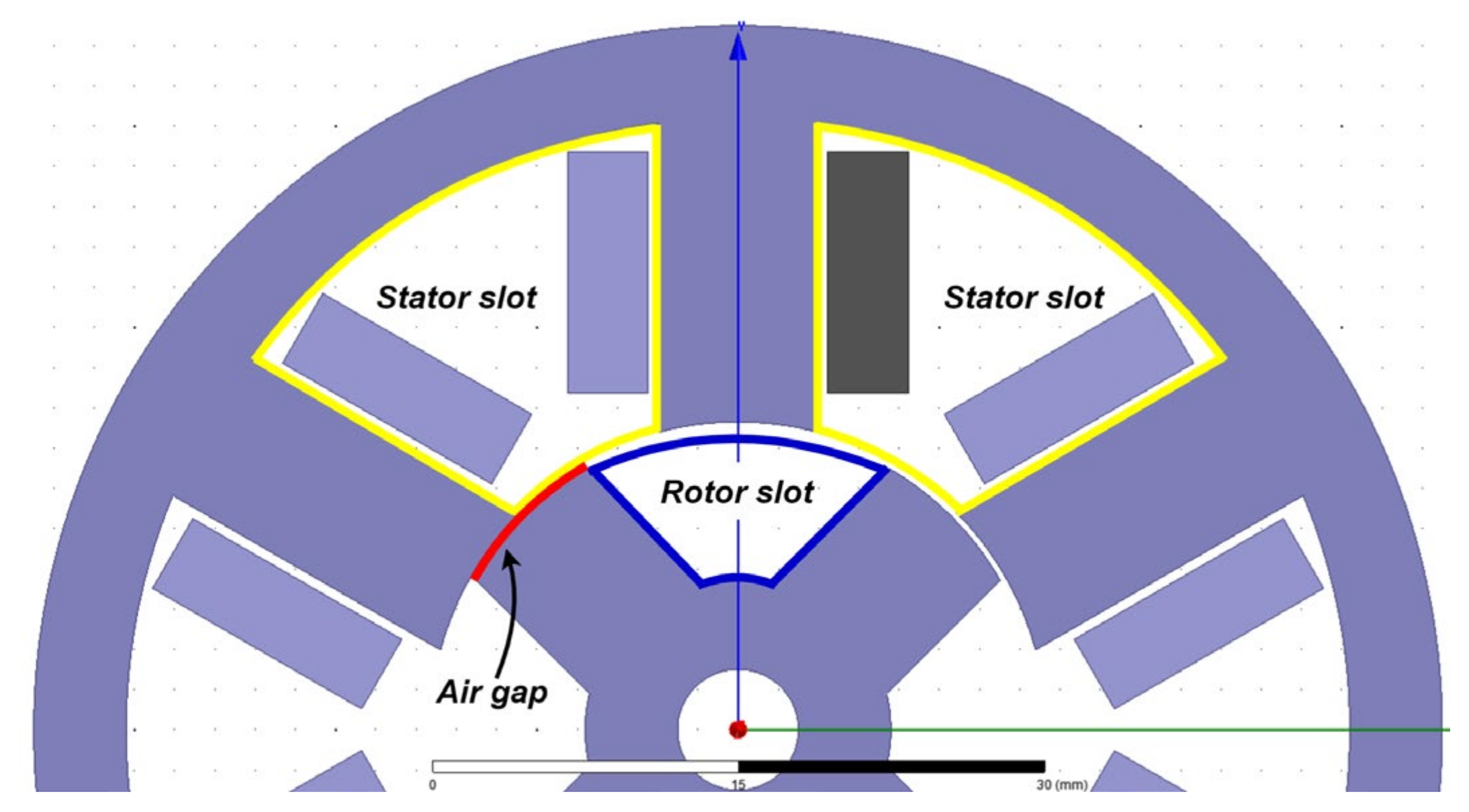
2. Air Gap Permeance

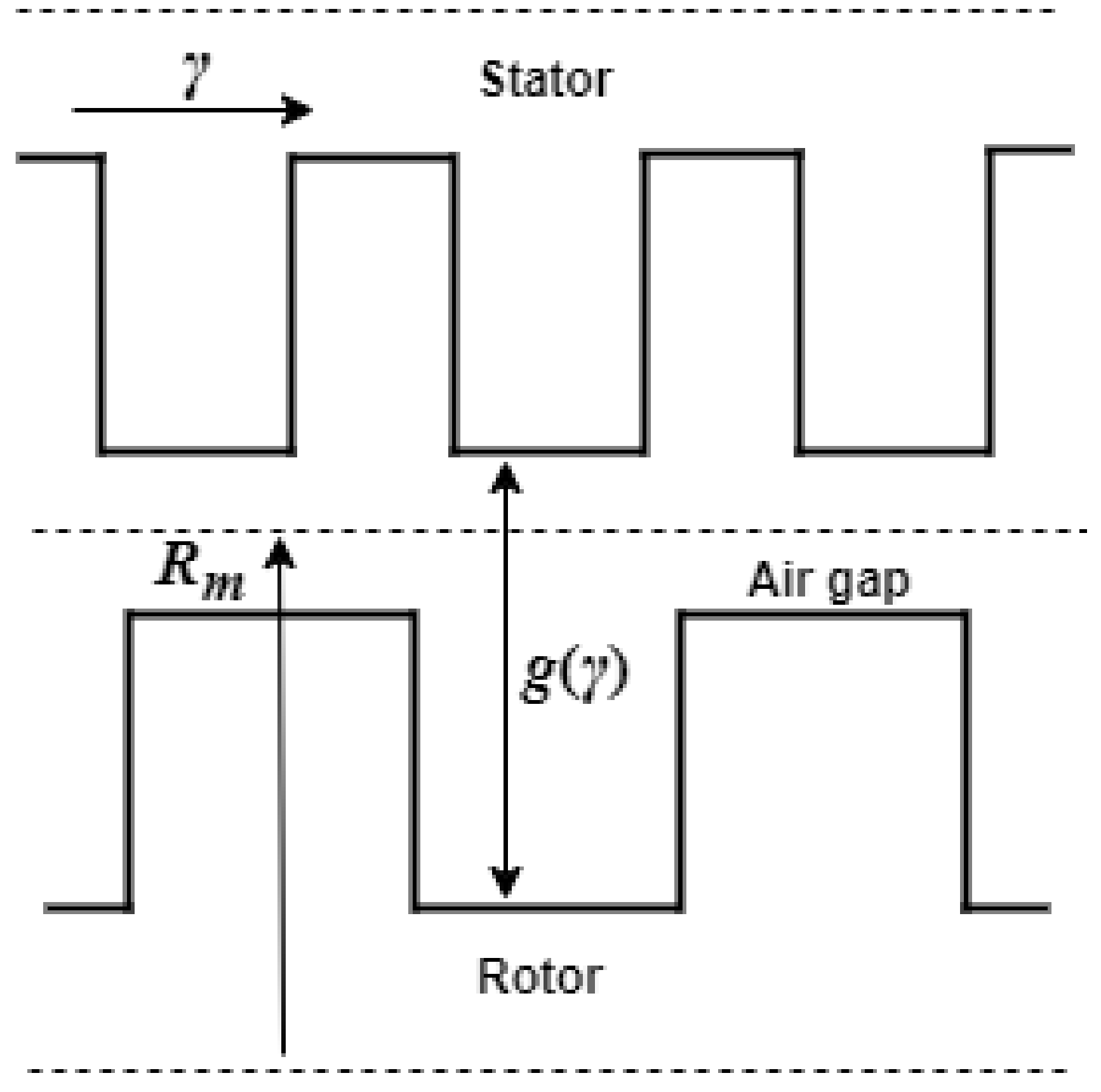
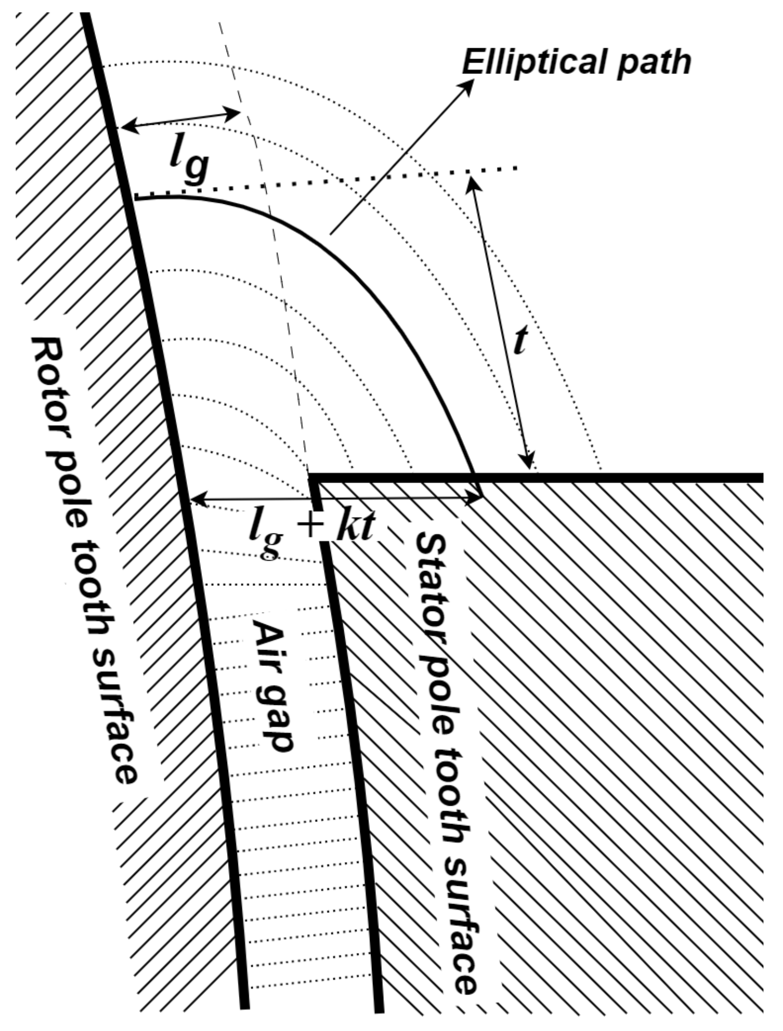
2.1. Theoretical Background

Air gap permeance uses the geometric properties of the air gap around the rotor to approximate the path to be taken by the magnetic flux in the air gap region of a machine. Various forms of Ampere’s circuital law are invoked to obtain the air gap magnetic field as a function of position around the motor. Often, very high or infinite iron permeance is also assumed so that all energy is stored in the air gaps of the machine. In basic magnetic field or circuit calculations, magnetic fields across air gaps are assumed to be uniform, and thus no fringing effects are considered. However, for reluctance motors, this is not necessarily always a valid assumption, especially when the rotor salient poles are too far from the active stator pole. Therefore, the problem of characterizing how flux jumps through an air gap considering fringing is a central issue when deriving analytical models for reluctance motors.
It will be seen in this section that previous works’ use of the term “permeance” when applied to magnetic field derivation techniques is not the same as the textbook definition from magnetic circuit theory (i.e., magnetic permeance is the inverse of magnetic reluctance). To maintain consistency and keep the intent of the original authors of the cited literature, the respective referenced materials’ own terminology and variables will be used when discussed in this review.
In a previous work [15], it was asserted that the shape and slotting of the air gap due to the salient poles around synchronous machines is the source of torque, force, and noise production. In particular, it claimed to provide a novel Fourier series solution to the inverse p ( γ ) of the variation in air gap length g ( γ ) around a doubly slotted machine, which is essentially a conventional switched reluctance motor (SRM). This slotting notation is shown in Figure 1. This series representation is common when solving Maxwell’s equations in SRMs, as they usually naturally appear as solutions to differential equations with specific assumed boundary conditions. No results for the magnetic field or torque production were provided in [15], and it refers to g ( γ ) as the “effective air gap length for a doubly slotted revolving air gap”, while p ( γ ) is simply referred to as the inverse of g ( γ ) .
Assuming that the iron is infinitely permeable, it is presented that the magnetic field B(γ) (where γ is the called the “peripheral position around the air gap” in radians) is provided to be of the form:
B γ = μ 0 M M F γ g ( γ ) = μ 0 M M F ( γ ) p ( γ )
This equation and its variations appear to be the core equation of works that use air gap permeance to solve for the magnetic field, citing [15] as a source of their magnetic field B expression. In (1), the MMF is the distribution of the current excitation from the coils, and p(γ) is the quantity that will later be called “permeance” by different works. Of interest then is the Fourier series representation of p(γ). This is found by first finding g(γ), which is, in turn, found by measuring the depth of the stator and rotor slots from an imaginary smooth cylindrical surface with radius R m , as in Figure 1. Algebraic techniques can then be used to find the reciprocal of the Fourier series of g(γ) and thus find p(γ). The method of solving for p(γ) lays a foundation upon which most other analyses regarding magnetic flux path length in the air gap are based upon and has thus been referenced in other material.
This equation is related to the magnetic field of an idealized solenoid with radius R and of length L, with L ≫ R in vacuum: B = μ 0 N I L . From another perspective, the equation can be visualized as infinitesimally small solenoids (whose magnetic fields are along their long axis), distributed radially around the motor, whose lengths are equal to the air gap distances due to the slotting and rotor positions. However, unlike that idealized solenoid visualization, the magnetic field at one section of the machine might be affected by the magnetic field in a different section of the machine. One example cause of this dependence is the position of the rotor machine, which would shorten the path while elongating another depending on the rotor pole’s location. Thus, the relationship with respect to γ must take this dependence into consideration.
At its root, the solenoid equation comes from Ampere’s law, which has the following form in magnetostatic conditions:
B · d l = μ 0 N I
Here, B is constant along a chosen path, and the reluctance from the air gaps with permeability μ 0 dominates. The dl term separates into g(γ), as in (1). In effect, most of the MMF is assumed to drop in the air gap regions. Also, the work done by the magnetic field, from which torque may also be obtained, is shown to be of the form:
W m a g = μ 0 R m l 2 0 2 π   M M F γ 2 p ( γ ) d γ
where R m is the mean radius to air gap and l is the (longitudinal) length of the air gap. Using either input–output power considerations or co-energy analysis, the basic equation for torque production in an SRM can be shown to be dependent on the rate of change of the phase inductances per rotor position θ and the square of the current i, so that excitation polarity does not matter in terms of the sign of the torque T [16]:
T = 1 2 i 2 t d L θ , t d θ  

2.2. Using Air Gap Permeance for Reluctance Machine Analysis

In a similar approach [17], the flux linkage and back emf was solved from the magnetic field expression obtained for a 10 stator–8 rotor pole field excited flux-switching machine at no load. A difference in this particular application from [15] is the assumption of infinitely deep stator slots and circular paths for magnetic fields from the sides of the slots, so that the net length of the magnetic field is longer than what was considered previously. Figure 2 shows example assumed paths Γ 1 and Γ 2 . The equation used for the magnetic field in the radial direction is conceptually the same as (1):
B r ( υ , θ ) = μ 0 M M F e x c ( υ , θ ) Λ ( υ , θ )
The magnetomotive force M M F e x c ν , θ is further provided as:
M M F e x c ν , θ   ~   κ c ν , θ + n = 1,3 , 5 b n s i n ( K ν )
where b n and K are constants for the Fourier series of the MMF distribution function shown in Figure 3. The quantity κ_c is claimed to be the rotor scalar magnetic potential of the form:
κ c ν , θ = 0 2 π M M F e x c ν ,   θ Λ ν , θ d ν 0 2 π Λ ν , θ d ν
The concept of magnetic scalar potential will be discussed later, but for now it refers to the magnetic field distribution in a volume without current-carrying conductors (NI = 0). The purpose of κ_c, as claimed in the work, is to act as a compensation so that ∇∙B = 0. Referring to Figure 3, it serves to effectively cancel the offset of the MMF function so that the average value for the entire motor surface is zero.
In (5) and (7), Λ(υ,θ) is the inverse of the air gap distance distribution between the rotor and stator with the aforementioned circular path assumption included. Λ(υ,θ) is referred to as the air gap permeance function in [17], where υ and θ are the angular position around the air gap and the rotational position of the rotor, respectively. It has the form:
Λ υ , θ = 1 g υ , θ )
where g(υ,θ) considers the stator and rotor slotting along with the nominal air gap length e:
g υ , θ = e + δ s υ + δ r ( υ , θ )
Observing Equations (5), (8), and (9), Λ(υ,θ) is thus effectively seen as the same as p(γ) in (1), as defined in [15]. Given that this air gap permeance has units of inverse length, l e n g t h 1 , it deviates from the typical definition of permeance in electromagnetic theory as the inverse of reluctance m a s s 1 l e n g t h 2 t i m e 2 c u r r e n t 2 , or l e n g t h μ 0 μ r a r e a [18,19].
The choice for the assumed flux path (in Figure 2) in the motor slots may be vindicated, especially when a rotor pole is near aligned with the stator poles, given that most of the flux, especially in the aligned position, is near the tips of the poles, as shown in Figure 4.
In Figure 2, the flux paths from the two slot sides along angular position ν are assumed to follow Γ 1 and Γ 2 , which are quarter circular paths with lengths:
Γ 1 = π R s i sin ( ν 2 ) Γ 2 = π R s i sin ( β s θ s 2 ν 2 )
It is then taken that flux flows through both these paths, such that they are in parallel, Γ 1 | | Γ 2 . Hence, the effective stator path length δ s υ is computed to be:
δ s ν = π R s i 2 sin ( ν 2 ) sin ( β s θ s 2 ν 2 ) sin ( β s θ s 4 ) cos ( β s θ s 4 ν 4 )
where rotor path length δ r υ is derived in the same manner, completing Equation (9). There appears to be an inherent assumption with this parallel path approach in this stator slot air gap calculation that the flux is coming or going to both walls of the infinitely deep stator slot in Figure 2. This may be true when the rotor pole is unaligned with a stator pole, resulting in the flux going through both Γ 1 and Γ 2 , but this may not be applicable when the machine is either in the unaligned position or when only one stator pole currently has an energized coil. For example, in Figure 4c, where the rotor of a 6-4 SRM is at 30° out of aligned position, the paths already appear to be elliptical. Granted, this may be an extreme case due to the low number of stator–rotor poles resulting in huge air gaps when the rotor is close to the unaligned position. The circular path assumption could be acceptable for machines such as the 108 reluctance motor that this analysis was originally applied upon [17]. The parallel equation allows the shorter path to dominate, so this can be enough to counteract this slight inaccuracy. Overall, this approach of finding the effective path allows other possible formulations or even simplifications for different slot shapes. As an example, are the paths followed by the flux further away from the air gap still circular? Or would they elongate or form elliptical arcs of various lengths? By combining with other techniques, such as insights from FEA results or finding the magnetic potentials in these regions, better approximations for path shapes may be obtained.
In an approach the authors call the air gap magnetomotive force permeance model [21], the MMF F(θ,t) is composed of winding functions N X ( θ ) (sometimes also called the turns function) from a certain phase, expressed as Fourier sums [22]. Equation (12) shows this relationship. The winding currents from coils A, B, and C are also considered in the total excitation of the motor. Thus, the effect of multiphase excitation is more naturally included in the rotating rotor analyses:
F θ , t = N A θ I A t + N B θ I B t + N C θ I C ( t )
Equations in [21] have a term called Λ t o t a l , which they also call air gap permeance, as in [17]. However, Λ t o t a l ’s mathematical definition is different from [17] and is similar to that in [23] instead:
Λ t o t a l ( θ , t ) = g 0 · Λ s ( θ ) · Λ r ( θ , t ) μ 0
where t = time (relates rotor speed and thus angular position) and θ = spatial position around the air gap. g 0 in (13) is the nominal air gap distance of the machine. This equation can be compared to (8). Λ s and Λ r are the permeances modeled using an approach similar to that in both [15,17]; in fact, Ref. [21] also cites [17] as a reference. Given this similar definition of Λ, it is seen that the quantity used here is a scaling factor to g 0 instead of being an additive quantity, as in (9). Other works, such as [24], use this multiplicative definition as well. Observe that the computed effective path lengths for Λ s and Λ r are the same as in (10) and (11). The magnetic field is then:
B g θ , t = F θ , t · Λ t o t a l θ , t .
Finding the total flux is a relatively simple integration of the B along the chosen area around the air gap. However, the presented torque equation that is provided is not as straightforward:
T e t = l s t a c k R s i 0 2 π B g θ , t d F s ( θ , t )
F s θ , t = F θ , t · Λ s θ · g 0 μ 0 .
The integration is in terms of the stator MMF through d F s ( θ , t ) , instead of the spatial position around the rotor, for example. Detailed derivation is found in [25], which starts from the usage of a stator electrical loading quantity K s θ , t and then applying Lorentz force law. Specific electrical loading is usually defined as the density of the current-carrying conductors around the periphery of the electric machine whose SI units are in Ampere-turns/m. [16]. K s θ , t is then provided as having a form:
K s θ , t = 1 R s i d F θ , t d θ .
Thus, it can be shown that (18) follows, which in turn simplifies to (15) when the terms cancel:
T e t = R s i L s t k 0 2 π B g θ , t K s θ , t R s i d θ .
The authors of Ref. [21] applied Equations (12)–(18) to several SRM designs with FEM results as the benchmark for comparison. In Figure 10 of [21], the results of applying those equations to a 12-8 stator-to-rotor pole design with a current amplitude of 24A and current angle of 60°, resulting in an unsaturated condition, is shown. From an analysis of the torque plots in Figure 10 of the original work, the average values of the analytical results from the FEA were estimated to differ by 1.14 Nm, which represents only about 4.13% of the 27.54 Nm amplitude of the FEA waveform. It was also approximated to underestimate the minimum torque by 1.36 Nm and overestimate the maximum by only 0.74 Nm. These represent relative errors from FEA values of about 12% and −1.9%, respectively. A similar general trend was observed for the other motor topologies they modeled. It can be inferred from their plots that air gap permeance and FEA results agreed best when the stator and rotor poles were near the aligned positions, as seen in the good agreement in the minimum to maximum torque sections of the plot. The biggest errors appeared when the rotor was unaligned with the stator poles, which should also represent the high torque values due to the steepness of the slope of the inductance curve in those positions (see Equation (4)). The distance to FEA measurements appeared to be within 0.74 to 2.17 Nm, which could be acceptable for such an approximate approach as air gap permeance. It was claimed by the authors that the consideration of end effects could still improve the analytical model. However, it can be seen from their analysis that the most simplifying assumption was taking circular paths for the magnetic flux, which is likely not true, especially when the rotor and stator pole faces are furthest from each other, manifesting as errors in the torque plot.
In the 6-4 SRM example in Figure 4, it can be supposed that semicircular paths for the flux may be a safe assumption for small deviations from the aligned rotor position, depending on the stator–rotor pole relationship. An investigation into determining at which angle the errors start to become significant, and what a significant error means in the first place, may be of interest. For Figure 4c, it appears that at even relatively small angles, the paths have already become elliptical. Permeance computations using elliptical paths show that the eccentricity of the path is dependent on the air gap distance, as verified in FEA calculations [26]. Referring to Figure 5, it was specifically found that in an SRM with an air gap distance of l g , the semimajor axis is a multiple kt of the minor axis of length t. Moreover, k is a nonlinear function only of the ratio t / l g .
Equation (1) implicitly presumes that thepath length g(γ) modulates the field around the motor. These techniques are reminiscent of the derivation of the Carter coefficients [27,28], although Carter initially used conformal mapping techniques that produced more justifiable flux paths instead of the rather arbitrary but easier to handle choices discussed here. Carter’s coefficients were used to scale the base magnetic field value at the appropriate locations around the motor by considering the effect of the slotting of the machine in the flux flow, much like the air gap permeances solved above. While it is not technically a flux-path-based parameter, finding air gap lengths is certainly an important consideration for the coefficients’ derivation [29].
In general, air gap permeance techniques treat permeance as a quantity that considers the effect of the slotting of the machine, which also affects the magnitude of the magnetic field. It will be seen that compared to the next techniques, the math involved is relatively simpler. The use of Ampere’s law itself requires assumptions regarding the chosen closed loop around the current-carrying conductor, but authors do claim good agreement with simulated results. Due to the already defined concept of magnetic permeance, it might be more appropriate to refer to the quantities p(γ) or Λ t o t a l as an air gap permeance modulator or coefficient, since they only adjust how the computed MMF flows around the assumed paths in the motor and are not, strictly speaking, magnetic permeance themselves [21,30]. Despite nomenclature inconsistencies and path simplifications, the works claim small errors with the predicted outputs, such as torque production, compared to FEA results.

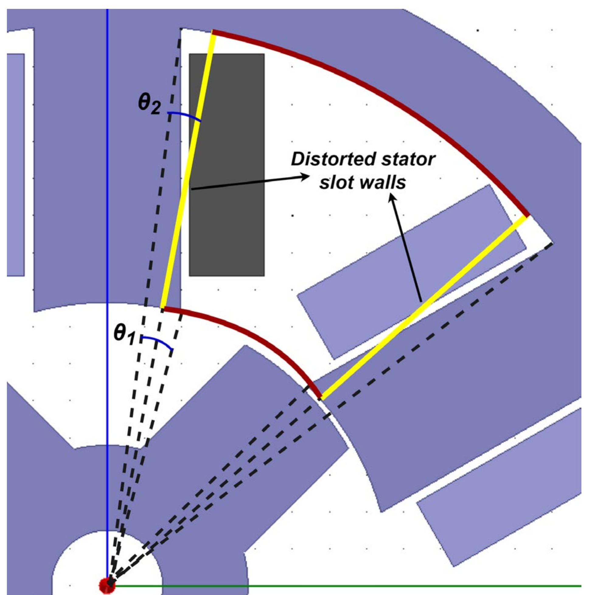
3. Magnetic Potentials

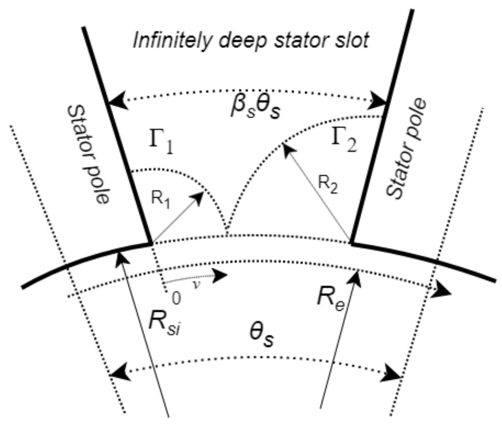
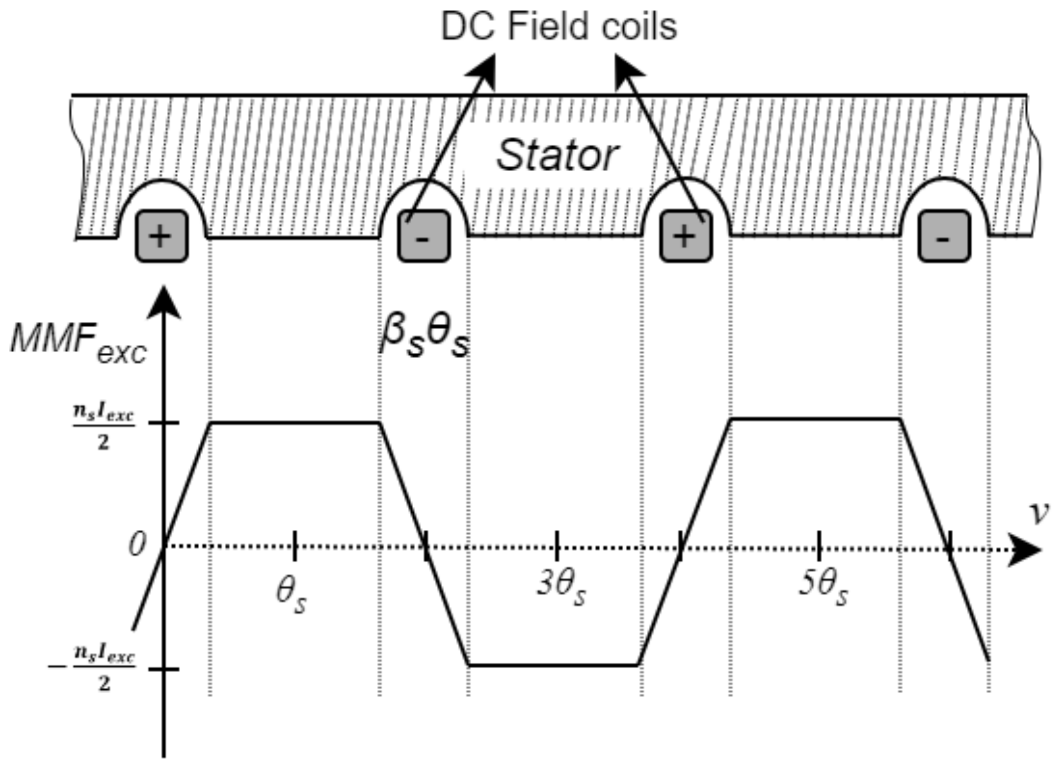
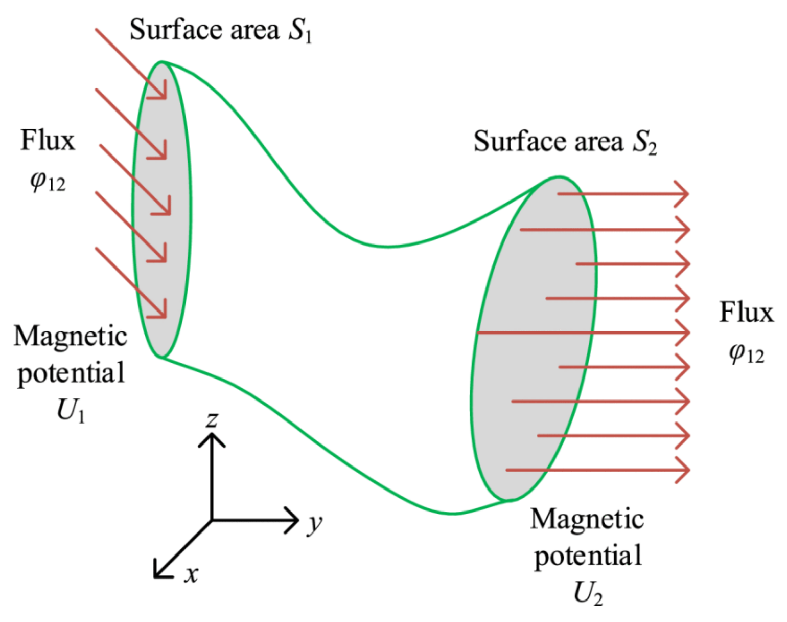
3.1. Theoretical Background of Magnetic Potentials

The derivation of the air gap permeance coefficient discussed in Section 2 relies on versions of Ampere’s law, which in turn uses presupposed flux paths. These paths may not be realistic for all rotor positions. To avoid such assumptions, it is possible to solve Maxwell’s equations for the magnetic potentials in the air region. This could more accurately predict how the flux flows more in the machine given only the phase excitation and boundary conditions imposed on the regions of the air regions.
Magnetic potential is analogous to electric potential and arises from the scalar and vector fields embedded in Maxwell’s equations. The magnetic vector potential’s (represented by A) existence in a region with non-zero current flow is guaranteed by Gauss’s law, Helmholtz’s decomposition theorem, and the fact that the divergence of a curl of a vector field is zero:
𝛁 · B = 0 = 𝛁 · 𝛁 × A .
The magnetic scalar potential, on the other hand, exists if there is no current source within the volume discussed [31]. While not as commonly utilized compared to the magnetic vector potential [32], it is useful for determining the magnetic field in zero-current volumes, such as around a permanent magnet or, in this discussion, in the air gap regions of reluctance motors. Aside from stator–rotor air gap regions, the magnetic scalar potential has been used to design flux barriers in synchronous reluctance machines as well [33]. For a volume in air without excitation current J:
B = μ 0 H
× H = J = 0 = μ 0   × B .
These equations are only valid for magnetostatic fields. From the fact that the curl of a gradient of a conservative field is zero in a simply connected region or volume, some corresponding magnetic scalar potential φ in this zero-current region must exist [32,34] (or, in other words, if the curl of a vector field is zero, then it is a gradient of a conservative potential field):
H = φ .
Simple connectedness in a region D implies that there are no holes in D; that is, every closed curve entirely within D only encloses points that are also included in D. The rotor slot, stator slot, and air gap regions, as shown in Figure 6, are indeed simply connected, and the magnetic scalar or vector potential equations described above should apply. It is a sufficient and necessary condition to guarantee the existence of such a scalar potential. (For completeness’s sake, it can be further pointed out that the statement “a vector field with zero divergence can be written as a curl of a potential field” is more strictly true only if the so-called second de Rahm co-homology of the vector field vanishes, but that is beyond the scope of this work and does not apply to real-life motor geometries. Simple connectedness should suffice for our purposes.) If the entire air gap of the machine is used instead of piecewise, as in [20], then there will be a rotor-shaped hole in the region, assuming that the iron is infinitely permeable (no drop in the MMF inside the iron sections). To make the model as accurate as possible, the entire air gap region, including the slots, must be accounted for, so the borders of the chosen subregions must be well considered. The magnetic potentials, as used, relate to the MMF around the motor. The units of φ can be shown to be in Ampere-turns [32]. Thus, the use of the MMF from the surface, used as boundary conditions for the differential equations, is justified.
In cylindrical coordinates, the magnetic scalar is then found to be of the form in (23), assuming uniformity in the z-direction, a safe assumption for motors in general, especially if end effects are excluded:
H = φ = φ r a r + 1 r φ a θ   .
This new definition can be applied to (20) and (21) to get the Laplace equation needed to be solved to obtain the magnetic flux density B from the magnetic scalar potential around the motor:
1 μ 0 · μ 0 𝛁 φ = 2 φ = φ r 2 + 1 r φ r + 1 r 2 2 φ θ 2 .
Similar logic is applied to obtain B from the magnetic vector potential, the difference being that the result is a Poisson equation due to the non-zero current density J z enclosed by the region:
B = × A = 1 r A z θ a r A z r a θ
μ 0 × 1 μ 0 × A = 2 A z = 2 A z r 2 + 1 r A z r + 1 r 2 2 A z θ 2 = μ J z .  
The only assumptions applied so far are those regarding the 2D magnetostatic scenario and infinitely permeable iron. The equations are not yet simplified to ease the derivation of the final expression. The realization here is that magnetic potential can be related to the magnetomotive force provided by the windings, which are more readily known or designed. At the same time, it is based solely on Maxwell’s equations. The only assumptions here would come from how the boundary conditions of the MMF are imposed, e.g., magnetic potential is zero at the surface and inside iron sections. There is no need to assume certain flux path shapes, as this will naturally arise from the solution to the differential equations and the boundary conditions chosen. Neglect of end effects and assumption of uniform z-axis B distribution is taken for granted. Thus, this approach enables one to get a more theoretically grounded solution for B given only the MMF distribution around the machine, with reasonable assumptions for the boundary conditions.
The flux linkage of a phase coil with N number of turns is found by simply applying the classic definition of linkage (number of turns multiplied by the flux in a loop of a coil), as seen in (27). Care must be taken to properly include either H r or the H θ component in computing the total flux around the air gap; whichever one depends on the specific method. Equation (27) explicitly excludes tangential components and can affect the accuracy. Inductance at a given a current I is then simply the ratio λ I . There are also other works [26] that have a permeance (P)-based definition of the form L = N P , where N is the number of turns of the coil:
λ = 2 N μ 0 R r o u t θ 1 θ 2 H r , θ d θ .
The solutions to the homogeneous Laplace’s equations are derived using separation of variables, which is of the form:
φ r , θ = n = 1 ( A n r n + B n r n ) ( C n cos m n θ + D n sin m n θ )
where the constants A n to D n are to be determined from the assumed boundary conditions. The summation implicitly takes care of Fourier series usage to express the boundary conditions.

3.2. Applying Magnetic Potentials to Reluctance Motors

The three regions assumed for the 6-4 switched reluctance motor are shown in Figure 6. This general approach can be thought of as an expansion of the air gap analysis in Section 2 in that it also includes the stator and rotor slot areas in the analysis. Instead of assuming paths of different shapes and lengths within the stator and rotor slots, the magnetic field distribution naturally arises from the equations and chosen boundary conditions.
In assuming near-zero reluctance of the iron core sections, it is implied that the iron surfaces have zero magnetic scalar potential, φ = 0 , if no magnetic flux comes out from that surface. Handling surfaces with magnetic flux flows, on the other hand, requires analysis. It is also put forward that the magnetic scalar potential can be derived from the MMF distribution around the motor. Whether these assumptions are supported or validated by theory can be a subject of future studies or at least be justified with FEA results.
A major simplification is due to the nature of the chosen general solution to Laplace’s and Poisson’s equations. The separation of variables used to gain (28) eases derivations if the boundary conditions are also separated in terms of r and θ. Thus, calculations will be relatively simpler if the walls of the stator and rotor slots and the current conducting coils are assumed to be radial from the center, because this will remove the θ-dependence of the boundaries. Observing Figure 6, the stator slot walls are not directed radially toward the center of the motor and instead are parallel to each other when in the same pole. Thus, if cylindrical coordinates are used, the equation for that wall is not solely in terms of r and θ because they will vary simultaneously in both coordinates. This, of course, is a common motor geometry, as it eases the insertion of windings. This is also mostly true for the rotor slots of conventional SRMs, although in this case the rotor slot walls are indeed directed radially. Thus, for this approach, some distortion of the stator slot region is required to obtain a tenable solution. This distortion is in the form of the assumption that the stator slot walls are now directly radial with equal angular difference at the inner and outer sides of the stator walls, as demonstrated in Figure 7. For smaller motors, the deviation between the distorted outer and inner walls (red arcs in Figure 7) against the real walls may be small enough that the effect on the solution is negligible.
A similar adjustment must be applied to the current-carrying coils or windings while maintaining the total current flow. Coils are commonly modeled in 2D as rectangular boundaries with area a c o i l , with some corresponding current area density, as in Figure 6. However, given the (r,θ) dependence of the solutions, solving Equations (25) and (26) is thus simplified by distorting the coils while preserving the total current. It can be reshaped to be a sector of a circle with the same height as the previous coil model height; this way, the region with non-zero current is bounded simply between some constant angles θ 1 α θ 2 and constant radii r 1 r r 2 . With the original undistorted current density scaled such that it is J m when the motor radius is 1 m, the following current distribution is then imposed:
J r , θ = J m r ,               θ 1 < θ < θ 2 0 ,                           o t h e r w i s e .
This is used so that the current density linearly varies, as with the radius. Using the angle as a parameter may result in the involvement of trigonometric functions (see (28)) in the downstream solutions and thus is not preferred. The inductance of an active phase with current I is then obtained from its classic definition, using the flux linkages found for each air region:
L = λ a i r + λ r o t o r   s l o t + λ s t a t o r   s l o t I .
All these assumptions regarding the solutions and motor geometry are claimed to result in a fairly accurate reproduction of FEA results, as seen in the plot in Figure 8 in the original paper [35]. In [35], the results are close to FEA in steep sections of the inductance curve, which represent rotor positions away from aligned positions. At the aligned position, which has the maximum inductance, the magnetic potential solution overestimates FEA by 0.56 mH, representing an error of about 4.53% from the simulated value of 12.40 mH. The minimum is underestimated by the analytical method by 0.215 mH, an error of −10.27% from the simulated 2.095 mH. With (4) and given the relative flatness at the extrema of the curve, these absolute errors should not visibly manifest in the torque curve, and as such the agreement between those positions implies similar accurate torque plots when the rotor is between the unaligned and aligned positions. The inaccuracy at the unaligned position may be because flux flow is more distributed at the air region at such a position, which can magnify errors due to the distortion performed for the stator slot region. When the rotor is aligned to the stator, most of the flux is in the small air gap region between the pole surfaces, resulting in less utilization of the distorted stator slow walls.
It is expected that the least accurate result would be when the rotor pole face does not fully line up with the stator pole face, resulting in more flux flowing through the slots instead of the more predictable short air gap between the pole faces. The assumed modifications to the motor geometry are merely mathematical devices to untangle the differential equation solutions for cylindrical coordinates and so are not strictly necessary. Without them, the simultaneous variation in the r and θ coordinates of the motor slots and conductors would be more challenging to obtain. It is then worth pointing out that despite these changes, FEA results are claimed to be reproduced quite well.
The results of magnetic potential analysis and air gap permeances are based on the geometry of the motor. Despite the significant assumptions or spatial distortions of the regions involved in the solution, results seem to be faithful to simulated outputs. As the previous derivation showed, analyses that simplify or distort motor geometry still produce solutions that approximate numerical results. This poses a potential problem of determining which reluctance motor dimension introduces the most significant contribution to the output. From [35], it seems that the method that can reproduce the most accurate answers at the extrema positions might be the most useful, since inductances in the intermediate rotor position are already reproduced well. The solutions produced by the magnetic potentials approach rely heavily on the chosen boundary conditions. The magnetic potentials approach has fewer base assumptions necessary compared to the air gap length approach, though it does need some geometry distortion to ease out results. Also, given that this approach includes slot regions, it is of interest to how this could be applied to other reluctance motor topologies, such as segmented stator and/or rotor machines. Given that segmentation, the bottom of the slots will only have air that can be seen as extending to infinity. What would the boundary condition for that then be?

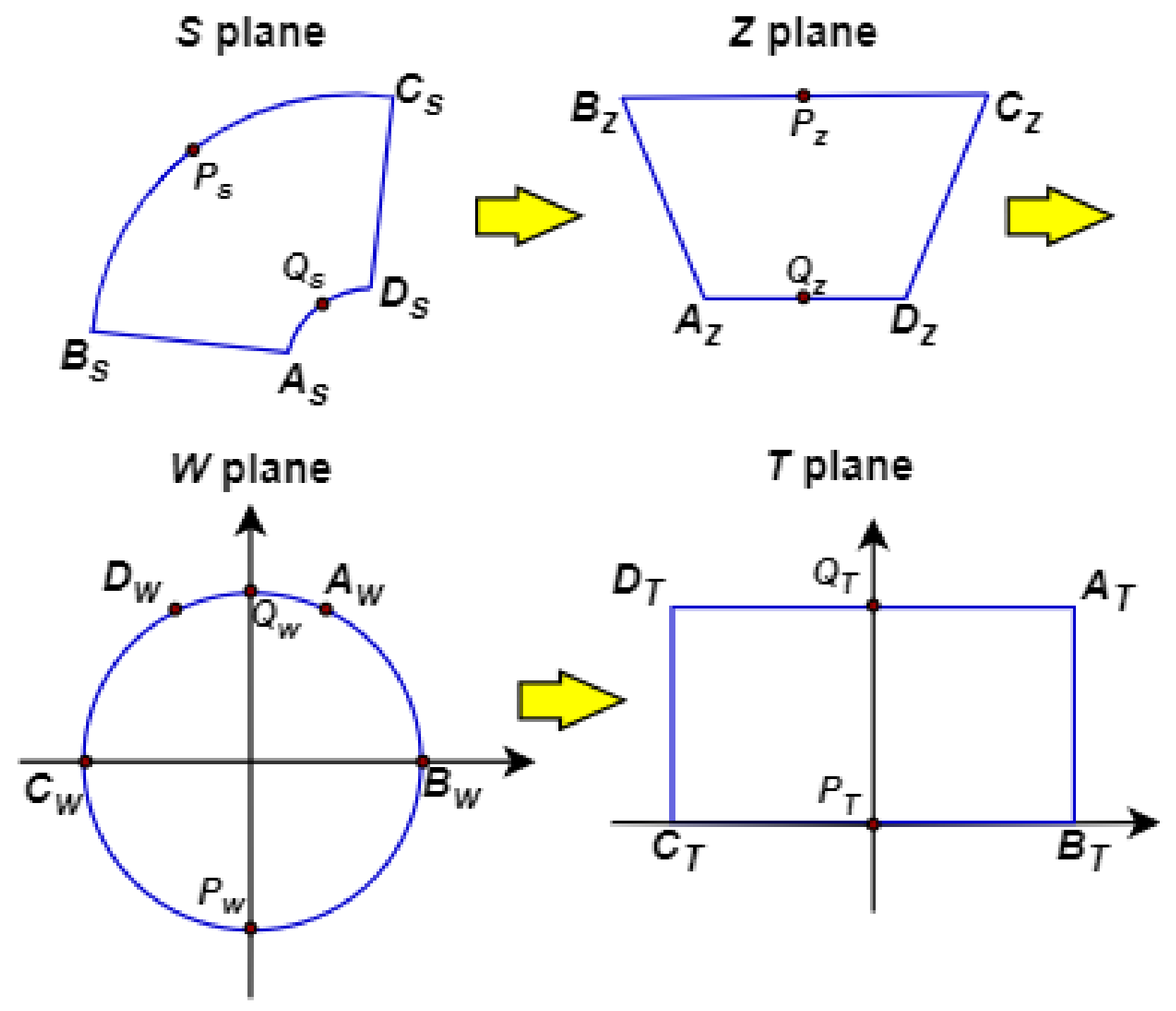
4. Conformal Mapping

4.1. Theoretical Background of Conformal Mapping

Inherent to discussions in Section 2 and Section 3 are some assumptions regarding the paths or shape of magnetic flux and/or potentials. These are adopted due to the complicated shape of salient poles of electric motors combined with the variation with rotor position, especially when the rotor and pole faces are unaligned. While these appear to produce analytical results with acceptably small errors compared to FEA, the effect of such deviations from the theoretical path might be minimized by applying conformal mapping techniques.
Conformal mapping is the transformation between functions in the complex plane that preserves the angles between two vectors while not necessarily preserving length. As an example, in Section 3, complicated boundaries introduced by the stator and rotor slots result in difficult-to-solve potential fields, which prompted some design simplifications to ease solvability. Through conformal mapping, these boundaries are transformable to a different geometry with a much easier to solve potential field (e.g., parallel plates separated by a distance) using the appropriate transform equations [36,37], and vice versa. A common form of conformal mapping is the Schwarz–Christoffel (SC) transform.
The basis of the SC transformation is that the upper half of the complex plane can be mapped into the interior Γ (a different variable from Section 2) of polygon P with interior angles a 1 π to a n π using the conformal map f(z):
f z = A + C z k = 1 n 1 ζ z k a k 1 d ζ .  
P has vertices w 1 to w n . The result will be such that w k = f z k for k = 1, … n − 1 [37]. Then, f(z) takes the locus of points in P as input and gives out a different set of points, hence a transformation. Obtaining the values of A and C may not be trivial and may depend on the shape and boundary conditions of the problem. Equation (31) partially stems from the fact that a multiplication of a complex position vector by another complex number in the complex plane can be imagined to result in a rotation and/or scaling of that vector; thus, a locus of such points can be transformed to a different curve with the proper complex number. This is why (31) is a product Π of several terms.
The derivative of f(z) in (31) is equal to:
d f z d ζ = C ζ z k a k 1 .
Given that integration is usually more difficult than derivatives, this form could be easier to manipulate, especially when the derivative on the left side is easy to obtain from the chosen transformation; in fact, this is done in [20]. For example, in Figure 8, B s C s and A s D s in the S-plane are concentric circular arcs with different radii. By using the function ln z as the transformation from S-plane to Z-plane, those arcs are transformed to straight lines B z C z and A z D z since they are a constant distance from the center in the S-plane [20,38]. In the S-plane, therefore, the result of using this transformation equation is:
d z d S = 1 S .
This can then be substituted back into (32) along with the properly determined vertices z s .

4.2. Conformal Mapping in Reluctance Motor Analysis

Conformal mapping is not a machine design tool per se but is instead a mathematical device arising from the properties of the complex plane. This tool is suited for solving electric motor fields because the slotting and air gap geometry of most reluctance motors can be somewhat simple. An early application of conformal mapping in electric motors is in the original derivation of Carter coefficients [27]. The SC transformation is commonly used and has been applied to electric motors as well [38,39,40]. It can be used to quantify the saliency [41] or slotting of machines in parallel using Carter coefficients [42]. An air gap use-case not utilized for slotting considerations is in the design of flux barriers for synchronous reluctance machines [43]. Of note in [43] is the usage of circular geometry for the barriers to take advantage of the relatively simple mapping of circular sections, as described in (32) and (33). Flux barriers in synchronous reluctance motors can be more complex than simple slotting in the switched versions but are analytically solvable with this method. Another example of its application is performed during an extension of the work in [35] to include SC transformations to better compute for the magnetic potentials in the chosen regions.
The usage of magnetic potentials with and without conformal mapping has been tried in [20,35], respectively, using the same 6-4 motor design. The conformal transformation process is shown in Figure 8 above. The inductance results of the conformally transformed motor are shown in Figure 8 of the original paper [20], which can be compared to the result from [35] that was discussed in Section 3.2. Compared to [35], the minimum inductance of about 3.55 mH, which occurs at the unaligned rotor position, is now nearly identical to the FEA result. The same is true at 5A of excitation, where the conformal analysis inductance’s maximum value at the aligned position overestimates the FEA maximum of 18.27 mH by 0.286 mH, representing a relative error of only 1.5%. This improvement is likely due to the removal of the distortions for the slot regions present in the previous magnetic potential analyses. It can be inferred that their conformal mapping implementation reasonably approximates the static inductance of the machine, as in the previous one without any conformal mapping. It is further claimed that in terms of percentage errors, the conformally mapped solution produced an error within approximately 1 to 8% of FEA benchmark values compared to the previous work’s range of 7–25%. However, this is all in consideration of the 2D case only, so the inclusion of end effects may present an interesting challenge.
The utility of the SC transformation in magnetic potential analysis is that it can be proved that once the magnetic field B is solved in the transformed polygon, there is no need to reverse-transform the results back to the original plane [20,38]. When the correct coordinates and transformed boundaries are considered, the results obtained are numerically equivalent, and the magnetic potential values for the original geometry are found as well. The exact forms for f k are determined from the chosen distribution of the vertices of the original polygon to the half plane, and so careful analysis of how to distribute the vertices of the old polygon to the new region must be performed. As can be seen in the SC equation above, the resulting integrals or derivatives may not be trivial to solve for, and numerical methods may be necessary. With careful consideration to the geometry, as in [20], the transformation f(z) can have a form and solution that are still analytic.
The choices of transformation to be made are rather arbitrary, but the choice should ease the derivation for (31) and (32). This choice of half-plane vertex locations is important so as not to distort the shape, so to speak. For example, if the side of a polygon is a straight line, the choice of f k for that side must be such that the transformed shape is also straight by the definition in the new coordinate system. This can be seen again in Figure 8 above. Given the possible difficulty of obtaining the integral in (31), this method may cease being analytic if numerical techniques are involved in solving the integral.
Conformal transformation, especially the SC transform, presents a promising approach that combines mathematical rigor with minimized simplifications regarding the geometry and flux path of the machine. Applying finite magnetic permeability values could be an additional step in its application as well. There has also been research that combines this with magnetic equivalent circuit analysis for synchronous reluctance motors [44]. In fact, given its nature, it could be applicable to any technique that utilizes magnetic potentials as a step in its derivation.

5. Summary of Major Techniques

Table 1 shows a summary of the major magnetic field solution techniques presented in this work. These approaches are not seen as mutually exclusiveinsights from one approach can be used to reinforce assumptions in another. They can then also be further extended, such as with the inclusion of saturation by using MEC analysis. As was discussed, they are ultimately based upon Maxwell’s equations and their attendant equations. They differ in how the quantities required are computed from the motor. End effects are not included in their analyses, and the cores are assumed to have very low reluctance. Once B is derived, quantities such as inductance, force, and torque can be relatively straightforward to compute with Lorentz force law, though the exact formulations vary.
Obtaining precise solutions to Maxwell’s equations for actual motor structures is difficult and can result in overtly complicated solutions. Simplifications due to geometric symmetry, coil/phase current distribution, and boundary conditions for the reluctance motors ease the solutions but ultimately affect the accuracy of the results to some extent. FEA results are an accepted reference point for determining the accuracy of proposed techniques’ solutions in published literature. Magnetostatic studies claim good agreement, as in the works previously mentioned in this paper.

6. Other Techniques Used in Reluctance Motor Research

There are other techniques used in mathematically analyzing the magnetic behavior of reluctance machines. The following techniques do not directly solve for B and are not strictly for analytically deriving it. However, they provide additional means of extending the work previously described to areas not allowed by their assumptions. These areas include realistic BH curves, magnetic saturation, and force/vibration production in the entire motor body. Thus, a complete review of magnetostatic derivations must consider the following methods.

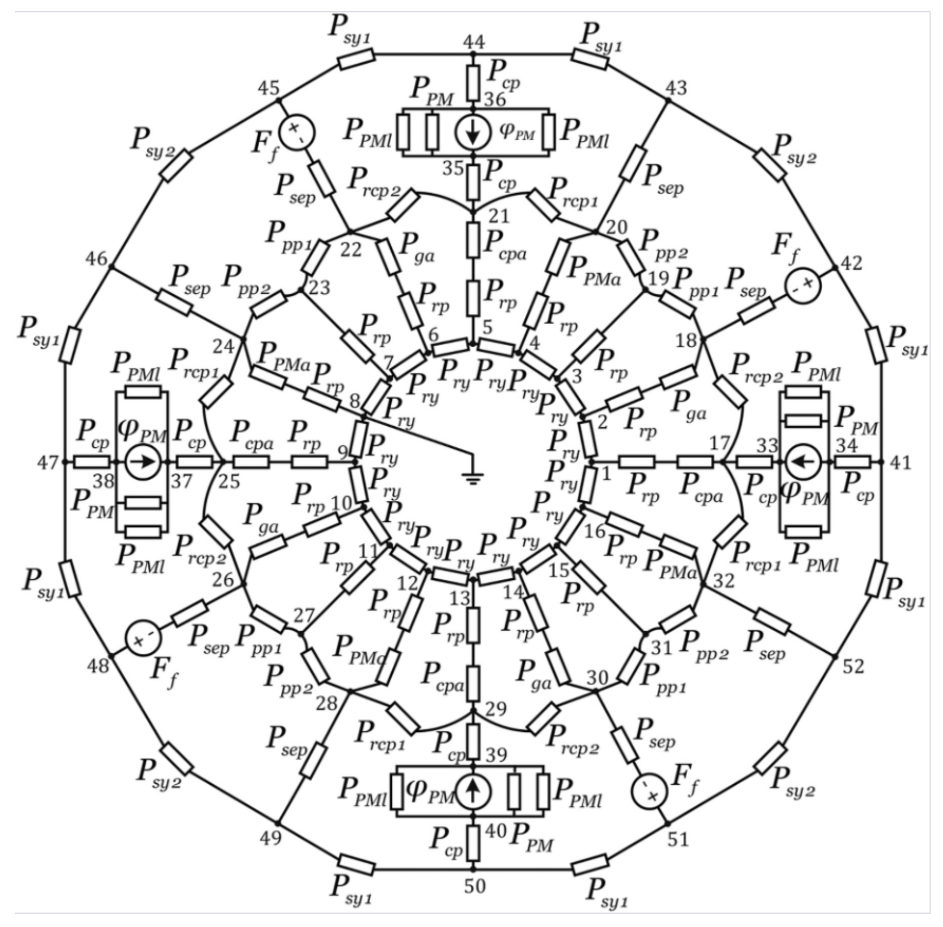
6.1. Magnetic Equivalent Circuits

The air gap permeance method can be seen as a subset of the more general magnetic equivalent circuit (MEC) approach. Usually, assuming a specific value of the relative permeability μ r , the magnetic flux, reluctance, and MMF are used analogously to the electric current, resistance, and voltage, respectively. By assigning those values to the different sections of the motor, a magnetic equivalent circuit can then be solved. An example of such a circuit for an SRM is shown in Figure 9.
It is commonly used in reluctance motor analysis and can also be used in conjunction with the previously described methods, especially when saturation and realistic μ r are to be included in the analyses, as in Figure 10 [45]. Other possibilities are using fluxes solved from air gap permeance techniques [21] or conformal analysis [20] at various excitation currents and rotor positions and then updating the flux values of the magnetic circuit. An example in Figure 11 shows magnetic potential usage with MEC [20]. It can even be applied to segmented motor designs [45,46] since the reluctances can be assigned freely. This freedom also enables choices regarding which sections to ignore or how to include leakage fluxes due to fringing [47]. It may also be used when nonlinearity or saturation is considered [48].
The MEC may be solved analytically but it is often used in an iterative manner until some chosen error criteria are passed. It generally does not provide a specific picture of how the magnetic field is distributed around the motor—in fact, the reverse approach is taken. The flux is assumed to flow in certain iron and air gap regions first, upon which a reluctance element is applied to that path. This is unlike analytical methods, where this distribution develops from the assumed boundary conditions and geometry of the machine. MEC does relatively easily accommodate changing permeability conditions around the machine.

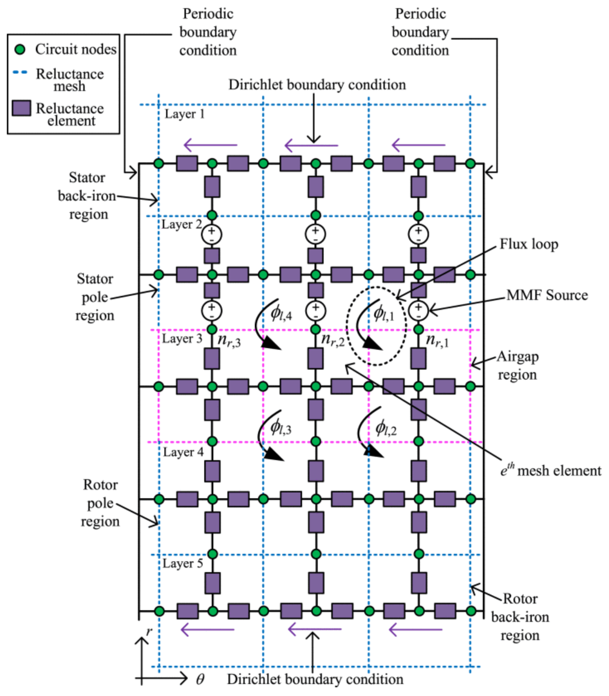
6.2. Reluctance Mesh and Flux Tubes

The reluctance mesh method can be viewed as middle ground between MEC analysis and finite difference techniques. The iron structure and air gaps of the motor are discretized into mesh elements, as exemplified in [49,50] and shown in Figure 12.
The potentials assigned at the nodes follow from the discretization of magnetic scalar potential in (22). A related element in this analysis is the flux tube [49]. This is an element in the discretized electric motor with arbitrary shapes, as seen in Figure 13, from whose side no flux leaks. It has also been employed in assuming flux flow in the air gaps at the aligned and unaligned positions [51], as in Figure 14. This is effectively a more flexible magnetic circuit element whose shape can be assigned based on assumed shapes of the flux paths. This includes circular sectors and trapezoidal volumes [11].
The discretization and solution steps of this method can conceivably be performed manually, but it best lends itself to a programmatic approach, as in numerical techniques for differential equations. While it does not provide an expression or equation for the resulting magnetic field distribution in the motor, it is useful in modeling nuances in the magnetic field distribution similar to MEC but with more degrees of freedom due to the possible shapes of flux tubes.

6.3. Maxwell Stress Tensor

The Maxwell stress tensor (MST) is an expression for the strain tensor used primarily for computation of forces due to the electromagnetic field in a certain volume. There are a variety of equivalent forms of expressing the tensor σ , and one is shown in (34) in cartesian coordinates containing only a magnetostatic field [52]:
σ = B x 2 1 2 B 2 B x B y B y B x B y 2 1 2 B 2 .
This can be integrated along the surface S of volume V to find the torque T exerted by the magnetic field [53]:
T = S r × σ · d S .
MST can be quite difficult to solve by hand for physical systems and was not often employed before widespread use of computers [54]. The choice of the path or surface in which the tensor integral is evaluated is one area of interest in the context of reluctance motors, especially considering the slotting of reluctance machines [55,56].
As the name implies, it is most useful when computing for forces and torques present in reluctance motors [11,57]. It is not generally used to solve for the magnetic field itself—it is instead assumed that the B field in the region to be solved is already known. It is also mostly used in regions with μ r = 1 , and co-energy techniques might be better suited for regions with varying permeability. An advantage is that it is directly obtained from Maxwell’s equations and deals with how the electromagnetic field itself exerts force. Thus, it can be used to solve forces, torques, or vibrations on a sounder theoretical basis once the magnetic field has been solved through other means.

7. Potential Applications to Segmented Reluctance Motor Design

The techniques discussed so far have been applied to reluctance motors with conventional structures; that is, they have the classic cylindrical stator and rotor with a continuous body made of essentially one piece of iron. Flux flows throughout the machine’s body and may enter the rotor through multiple poles [58]. An example is shown in Figure 15a.
However, given the fundamental nature of how switched reluctance motors operate, this conventional structure is not strictly necessary if the phases are properly commutated. In a way, it can be viewed much like a circularly arranged set of electromagnets consecutively attracting an iron rotor. For SRMs, it is possible to segment either or both the stator and rotor, with a nonmagnetic material securing them in place. Its advantages include a smaller amount of electrical steel used [60], efficient flux path distribution, torque improvements [61], and even increased fault tolerance through the employment of modular motor designs [62]. With a segmented stator, less MMF might be needed because the stator back iron will have small reluctance (if finite μ r is assumed). Granted, segmented structures also introduce new mechanical issues to be surmounted, such as ensuring the concentricity of the parts [63] and possible vibration due to imbalance if the rotor is segmented, but the advantages are enough to motivate further work. As an aside, segmentation can also be applied to motor drivers simultaneously because each SRM phase can be operated individually with no need for a common node, as in wye- or delta-connected drivers. There is also the fact that torque direction is independent of current direction. Asymmetric bridge converters (ABCs) can then be used to drive them [16].
Studies on analytic methods in solving the magnetic fields in such machines using the discussed analytical methods here are quite few. Magnetic equivalent circuits have been used in analysis of conventional stator, segmented rotor (CSSR) SRM designs [61]. Most existing work focuses on using the FEA-obtained rotor position–current–flux relationship of the machine, together with the classic voltage equation: d λ d t = V t R i ( t ) , from which the motor performance under different mechanical loading or motor drive scenarios can be modeled [64,65,66]. The usage of analytical techniques in segmented motors will have the same advantages as before, such as less computer power reliance and better mathematical insight into the input–output relationships of the machine. However, the discontinuous nature of the machine must impose a different set of necessary boundary conditions before the previously discussed methods can be applied. This different set of boundary conditions, combined with the usual reliance on simulation techniques for advantageous segmented machines, constitutes a problem suitable for mathematical analysis of the magnetostatic field of segmented motor designs. The resulting techniques can result in further advancement of this motor topology.
The flux flow is constrained to the nearest stator poles even when only the rotor is segmented. This can be seen in Figure 15b, which shows a CSSR design [58]. The concentration of flux is even more pronounced in the aligned position for a segmented stator, segmented rotor (SSSR) structure, as shown in Figure 16. In both cases, the rotor segments act as shunts for the flux leaving the nearest stator poles so that the position of highest inductance for the phase involved is achieved.
This near-total isolation between the magnetic sections of the SSSR motor can both simplify and introduce complications in applying the air gap permeance techniques. The flux produced by a phase will only be restricted to the pole tips of the rotor or stator segments involved, especially for SSSR motors. It is observed that the face of the rotor pole is almost always within nominal air gap distance until the rotor is at the unaligned rotor position, as depicted in Figure 17. Thus, the resulting permeance coefficient Λ ( θ , t ) could almost be perfectly uniform so there are few changes to the air gap distance along the air gap periphery, though this depends on the precise shape of the stator and/or rotor segments. The MMF distribution function may have a slightly different expression for its distribution depending on how the segmented stator is wound (especially if the phases are electrically isolated from each other), but it should mostly emerge out of the stator pole face close to rotor segments.
Fundamentally, it does not appear necessary in air gap permeance analyses to have a continuous motor structure as long as the MMF distribution and air gap paths are properly considered. It does appear that the flux flows through all the segments when the rotor is not aligned in the SSSR SRM, as in Figure 16b. Given the uniformity of Λ ( θ , t ) , it may then appear that the torque variation comes from the variation in the MMF along the air gap, or that the effect of this slotting due to the separated segments may be enough to induce an observable torque. This hypothesis merits investigation in future studies.
Applying magnetic potential techniques may be tricky, as the first question would be how to assign the boundary conditions. Theoretically, there should be no difference with the assignment as in a conventional machine. As discussed in Section 3, the potential is zero at the walls of the slots where the flux does not emanate and ± N I at the pole faces. The problem of how to assign boundaries in the regions between the stator and rotor segments must be addressed. In a conventional machine, the rotor slots are surrounded on at least three sides by iron and an air gap that could also have an MMF. In a segmented motor, as in Figure 17, a rotor slot is bounded on two sides by iron, another by the air gap with the stator, while the last can be seen as an air gap or slot that extends through the rotor. This last air gap may be viewed as infinitely deep from the point of view a rotor slot magnetic scalar potential. It is possible to set the machine center to be at zero potential. The opposite is the case for the intervening regions between the stator segments, whose slots (which can be seen as infinitely deep due to the absence of a bottom iron) face outwards from the motor. To set realistic boundary conditions for these situations, insights might be gained from preliminary FEA magnetic potential results. The stator segments do have similarly shaped salient poles as those in conventional structures (Figure 6 vs. Figure 16a) and so similar distortions as those discussed in Section 4.2 may be made to simplify computations. The rotor segments, on the other hand, usually have trapezoidal shapes [59,61,63], which complicate the resulting differential equation solutions. Solving equations (22) and (23) for spaces between the segmented rotors then requires further examination. The supporting tabs of the segments could be ignored, since very little flux flows in them, especially in the aligned rotor position, as in Figure 16a and Figure 17.
Conformal transformation (particularly the SC transform), however, may be especially suited for this segmentation boundary condition problem because of the underlying linearity of magnetic potentials and Maxwell’s equations. Each stator segment, which is a source of MMF, can be individually analyzed. For example, the SC transformation could be applied to a stator segment with the proper f(z) into a rectangular domain similar to the process schematically shown in Figure 8. This may allow the derivation of the magnetic scalar potential field produced by that single segment, upon which the effect of the other segments that are actively excited can then be added due to linearity. A caveat is that Figure 8 shows the process of transformation for the motor slots, not the stator or rotor segment or poles themselves, as in the situation just described. This slot-based transformation may, therefore, also be performed; in fact, the region between the stator segments can be imagined to be akin to a capacitor in that the walls of each segment (capacitor plates) are separated by a dielectric (air or aluminum), with one segment actively with MMF (positive voltage) and the other commutated off (ground). The potential field between two plates is an example problem commonly solved in conformal transformations, and could be applicable in a segmented stator context, thus avoiding complicated assumptions in assigning boundary conditions when basic magnetic potential analysis is applied. On the other hand, that scenario does not yet consider the effect of the nearby rotor segments, which will provide a flux path with less reluctance. In fact, it can already be seen in Figure 16b how the flux flows through the neighboring stator and rotor segments.
Overall, the application of the aforementioned techniques in the mathematical analysis of the magnetostatic field in segmented motor design is relatively unexplored, given that segmented motor analysis in the literature often involves FEA, the usage of reluctance motor properties, as exemplified by the classic flux linkage–voltage relation d λ d t = V t R i ( t ) and (4), or interpolation techniques. While approximate techniques for these machine topologies already exist [66], the aim is to provide a systematic, if not general, expression of inductance and torque production for segmented machines that are based on the fundamental distribution of the magnetic field.

8. Conclusions

Analytical methods for solving the magnetic field in a reluctance motor are derived from Maxwell’s equations, and there are various methods of making the problem tractable for the geometry of such a machine. Previous works focused on the application of these methods to various motor models instead of the analytical methods themselves. Mathematical models may be more desirable given the computational needs of numerical or simulation-based modeling.
In this review, the major techniques that rely on obtaining the magnetostatic field distribution using fundamental principles were discussed and analyzed. Other methods that also solve for the B field but are iterative were also shown. There are a multitude of possible ways to heuristically approach the motor magnetostatic field distribution employing different simplifications. However, the major techniques can be boiled down to using air gap permeance, magnetic potentials, and conformal transformations, and these appear to be able to support each other in reluctance motor research as well. Their mathematical details and assumptions were indeed examined here, and it was shown that it is not impossible to link them together, making them more accurate by strengthening their underlying assumptions using ideas from other techniques. They are all able to reasonably approximate simulated results; however, it appears that for saturated iron situations, magnetic equivalent circuit analysis is still the most relevant process.
As segmented stator and rotor designs have also emerged, possible applications of those analysis techniques in segmented motor designs were investigated. Avenues of approaching the analysis of such machines using the discussed derivations were thus conjectured and suggested as areas of future research. Air gap permeance must be set with different considerations with segmented rotor designs because of the near-constant air gap lengths between the stator and rotor pole faces. It is believed that conformal mapping is well suited for those with segmented stator designs, while magnetic potentials may allow for the solution of the magnetic field between the stator and rotor segments, which are only bound by iron on two sides. This machine topology has properties that are not present in conventional structures and whose systematic study must then pose an interesting area of mathematical analysis.

Author Contributions

Conceptualization, R.F.S. and L.A.T.; software, R.F.S. and L.A.T.; formal analysis, R.F.S.; investigation, R.F.S.; resources, R.F.S. and L.A.T.; data curation, R.F.S.; writing—original draft preparation, R.F.S.; writing—review and editing, R.F.S. and L.A.T.; visualization, R.F.S.; supervision, L.A.T.; project administration, L.A.T.; funding acquisition, L.A.T. All authors have read and agreed to the published version of the manuscript.

Funding

This research was funded by an Engineering Research and Development for Technology (ERDT) grant of the Department of Science and Technology (DOST) of the Philippines.

Data Availability Statement

Not applicable for this work.

Acknowledgments

The authors would like to acknowledge the support provided by the ERDT program of the Department of Science and Technology (DOST) of the Philippines, as well as that of the Electrical and Electronics Engineering Institute of the University of the Philippines Diliman.

Conflicts of Interest

The authors declare no conflicts of interest. The funders had no role in the design of the study, in the collection, analyses, or interpretation of data, in the writing of the manuscript, or in the decision to publish the results.

Abbreviations

The following abbreviations are used in this manuscript:
BEABoundary element analysis
CSSRConventional stator, segmented rotor
FEAFinite element analysis
MECMagnetic equivalent circuit
MMFMagnetomotive force
MSTMaxwell stress tensor
SRMSwitched reluctance motor
SCSchwarz–Christoffel (transform)
SSSRSegmented stator, segmented rotor

References

  1. Diao, K.; Sun, X.; Lei, G.; Bramerdorfer, G.; Guo, Y.; Zhu, J. Robust Design Optimization of Switched Reluctance Motor Drive Systems Based on System-Level Sequential Taguchi Method. IEEE Trans. Energy Convers. 2021, 36, 3199–3207. [Google Scholar] [CrossRef]
  2. Li, S.; Zhang, S.; Habetler, T.G.; Harley, R.G. Modeling, Design Optimization, and Applications of Switched Reluctance Machines—A Review. IEEE Trans. Ind. Appl. 2019, 55, 2660–2681. [Google Scholar] [CrossRef]
  3. Diao, K.; Sun, X.; Bramerdorfer, G.; Cai, Y.; Lei, G.; Chen, L. Design optimization of switched reluctance machines for performance and reliability enhancements: A review. Renew. Sustain. Energy Rev. 2022, 168, 112785. [Google Scholar] [CrossRef]
  4. Omar, M.; Sayed, E.; Abdalmagid, M.; Bilgin, B.; Bakr, M.H.; Emadi, A. Review of Machine Learning Applications to the Modeling and Design Optimization of Switched Reluctance Motors. IEEE Access 2022, 10, 130444–130468. [Google Scholar] [CrossRef]
  5. Shao, H.; Zhong, C.; Habetler, T.G.; Li, S. Multi-Objective Design Optimization of Synchronous Reluctance Machines Based on the Analytical Model and the Evolutionary Algorithms. In Proceedings of the 2019 North American Power Symposium (NAPS), Wichita, KS, USA, 13–15 October 2019; pp. 1–6. [Google Scholar] [CrossRef]
  6. Mecrow, B.; Finch, J.; El-Kharashi, E.; Jack, A. Switched reluctance motors with segmental rotors. IEE Proc.-Electr. Power Appl. 2002, 149, 245–254. [Google Scholar] [CrossRef]
  7. Ding, W.; Yang, S.; Hu, Y. Development and Investigation on Segmented-Stator Hybrid-Excitation Switched Reluctance Machines With Different Rotor Pole Numbers. IEEE Trans. Ind. Electron. 2017, 65, 3784–3794. [Google Scholar] [CrossRef]
  8. Widmer, J.; Mecrow, B. Optimised Segmental Rotor Switched Reluctance Machines with a greater number of rotor segments than stator slots. In Proceedings of the 2011 IEEE International Electric Machines & Drives Conference (IEMDC), Niagara Falls, ON, Canada, 15–18 May 2011; pp. 1183–1188. [Google Scholar] [CrossRef]
  9. Rallabandi, V.; Wu, J.; Zhou, P.; Dorrell, D.G.; Ionel, D.M. Optimal Design of a Switched Reluctance Motor With Magnetically Disconnected Rotor Modules Using a Design of Experiments Differential Evolution FEA-Based Method. IEEE Trans. Magn. 2018, 54, 8205705. [Google Scholar] [CrossRef]
  10. Ma, C.; Qu, L. Multiobjective Optimization of Switched Reluctance Motors Based on Design of Experiments and Particle Swarm Optimization. IEEE Trans. Energy Convers. 2015, 30, 1144–1153. [Google Scholar] [CrossRef]
  11. Watthewaduge, G.; Sayed, E.; Emadi, A.; Bilgin, B. Electromagnetic Modeling Techniques for Switched Reluctance Machines: State-of-the-Art Review. IEEE Open J. Ind. Electron. Soc. 2020, 1, 218–234. [Google Scholar] [CrossRef]
  12. Rocca, R.; De Donato, G.; Bolognesi, P.; Boccaletti, C.; Capponi, F.G. Improved Design-Oriented Analytical Modelling of Switched Reluctance Machines Based on Fröhlich-Kennelly Equations. IEEE Trans. Energy Convers. 2023, 39, 734–746. [Google Scholar] [CrossRef]
  13. Shi, M.; Wang, Q.; Li, G.; Xu, J.; Han, Q.; Ye, Q. A New Adaptive Analytical Model for the Spherical Reluctance Motor Based on Hybrid Trigonometric Function–Power Function. IEEE Trans. Ind. Electron. 2022, 70, 6099–6109. [Google Scholar] [CrossRef]
  14. Santos, R.F.L.; Tria, L.A.R. A Response Surface Method Approach to Modular Stator, Segmented Rotor Switched Reluctance Motor Design. In Proceedings of the 2020 IEEE 9th International Power Electronics and Motion Control Conference (IPEMC2020-ECCE Asia), Nanjing, China, 29 November–2 December 2020; pp. 484–489. [Google Scholar] [CrossRef]
  15. Hesse, M.H. Air gap permeance in doubly-slotted asynchronous machines. IEEE Trans. Energy Convers. 1992, 7, 491–499. [Google Scholar] [CrossRef]
  16. Krishnan, R. Switched Reluctance Motor Drives: Modeling, Simulation, Analysis, Design, and Applications; CRC Press: Boca Raton, FL, USA, 2001. [Google Scholar]
  17. Gaussens, B.; Hoang, E.; de la Barriere, O.; Saint-Michel, J.; Lecrivain, M.; Gabsi, M. Analytical Approach for Air-Gap Modeling of Field-Excited Flux-Switching Machine: No-Load Operation. IEEE Trans. Magn. 2012, 48, 2505–2517. [Google Scholar] [CrossRef]
  18. Fitzgerald, A.E.; Umans, S.D. Fitzgerald & Kingsley’s Electric Machinery, 7th ed.; McGraw-Hill: New York, NY, USA, 2014. [Google Scholar]
  19. Chapman, S.J. Electric Machinery Fundamentals, 5th ed.; McGraw-Hill: New York, NY, USA, 2012. [Google Scholar]
  20. Li, S.; Zhang, S.; Gong, C.; Habetler, T.G.; Harley, R.G. An Enhanced Analytical Calculation of the Phase Inductance of Switched Reluctance Machines. IEEE Trans. Ind. Appl. 2018, 55, 1392–1407. [Google Scholar] [CrossRef]
  21. Hua, H.; Hua, W. Analytical Prediction of Torque of Switched Reluctance Machines Considering Nonlinear Characteristics. IEEE Trans. Ind. Electron. 2021, 69, 190–201. [Google Scholar] [CrossRef]
  22. Lipo, T.A. Analysis of Synchronous Machines, 2nd ed.; CRC Press: Boca Raton, FL, USA, 2012. [Google Scholar]
  23. Zhu, Z.Q.; Howe, D. Instantaneous magnetic field distribution in brushless permanent magnet DC motors. III. Effect of stator slotting. IEEE Trans. Magn. 1993, 29, 143–151. [Google Scholar] [CrossRef]
  24. Wu, Z.; Fan, Y.; Chen, H.; Wang, X.; Lee, C.H.T. Electromagnetic Force and Vibration Study of Dual-Stator Consequent-Pole Hybrid Excitation Motor for Electric Vehicles. IEEE Trans. Veh. Technol. 2021, 70, 4377–4388. [Google Scholar] [CrossRef]
  25. Huang, L.R.; Feng, J.H.; Guo, S.Y.; Shi, J.X.; Chu, W.Q.; Zhu, Z.Q. Analysis of Torque Production in Variable Flux Reluctance Machines. IEEE Trans. Energy Convers. 2017, 32, 1297–1308. [Google Scholar] [CrossRef]
  26. Takemoto, M.; Suzuki, H.; Chiba, A.; Fukao, T.; Rahman, M. Improved analysis of a bearingless switched reluctance motor. IEEE Trans. Ind. Appl. 2001, 37, 26–34. [Google Scholar] [CrossRef]
  27. Carter, F.W. The magnetic field of the dynamo-electric machine. J. Inst. Electr. Eng. 1926, 64, 1115–1138. [Google Scholar] [CrossRef]
  28. Viorel, A.C.; Viorel, I.-A.; Strete, L. On the calculation of the Carter factor in the slotted electric machines. In Proceedings of the 2014 International Conference and Exposition on Electrical and Power Engineering (EPE), Iasi, Romania, 16–18 October 2014; pp. 332–336. [Google Scholar] [CrossRef]
  29. Parasiliti, F.; Villani, M. Magnetic analysis of flux barriers Synchronous Reluctance Motors. In Proceedings of the 2008 18th International Conference on Electrical Machines, Vilamoura, Portugal, 6–9 September 2008; pp. 1–6. [Google Scholar] [CrossRef]
  30. Cheng, M.; Han, P.; Hua, W. General Airgap Field Modulation Theory for Electrical Machines. IEEE Trans. Ind. Electron. 2017, 64, 6063–6074. [Google Scholar] [CrossRef]
  31. Hannon, B.; Sergeant, P.; Dupré, L.; Pfister, P.-D. Two-Dimensional Fourier-Based Modeling of Electric Machines—An Overview. IEEE Trans. Magn. 2019, 55, 8107217. [Google Scholar] [CrossRef]
  32. Vanderlinde, J. Classical Electromagnetic Theory, 2nd ed.; Springer Science + Business Media, Inc.: Greer, SC, USA, 2005. [Google Scholar]
  33. Bacco, G.; Bianchi, N. Design Criteria of Flux-Barriers in Synchronous Reluctance Machines. IEEE Trans. Ind. Appl. 2018, 55, 2490–2498. [Google Scholar] [CrossRef]
  34. Helrich, C.S. The Classical Theory of Fields: Electromagnetism; Graduate Texts in Physics; Springer: Greer, SC, USA, 2012. [Google Scholar]
  35. Li, S.; Zhang, S.; Dang, J.; Habetler, T.G.; Harley, R.G. Calculating the unsaturated inductance of 4/2 switched reluctance motors at arbitrary rotor positions based on partial differential equations of magnetic potentials. In Proceedings of the 2015 North American Power Symposium (NAPS), Charlotte, NC, USA, 4–6 October 2015. [Google Scholar] [CrossRef]
  36. Gibbs, W.J. Conformal Transformations in Electrical Engineering; The British Thomson-Houston Co., Ltd.: Rugby, UK, 1958. [Google Scholar]
  37. Driscoll, T.A.; Trefethen, L.N. Schwarz-Christoffel Mapping; Cambridge University Press: Melbourne, Australia, 2002. [Google Scholar]
  38. Zarko, D.; Ban, D.; Lipo, T.A. Analytical calculation of magnetic field distribution in the slotted air gap of a surface permanent-magnet motor using complex relative air-gap permeance. IEEE Trans. Magn. 2006, 42, 1828–1837. [Google Scholar] [CrossRef]
  39. Costamagna, E.; Barba, P.D.; Savini, A. An effective application of Schwarz–Christoffel transformations to the shape design of permanent magnet motors. Int. J. Appl. Electromagn. Mech. 2005, 21, 21–37. [Google Scholar] [CrossRef]
  40. Krop, D.C.J.; Lomonova, E.A.; Vandenput, A.J.A. Application of Schwarz-Christoffel Mapping to Permanent-Magnet Linear Motor Analysis. IEEE Trans. Magn. 2008, 44, 352–359. [Google Scholar] [CrossRef]
  41. Ilhan, E.; Motoasca, E.T.; Paulides, J.; Lomonova, E. Conformal mapping: Schwarz-Christoffel method for flux-switching PM machines. Math. Sci. 2012, 6, 37. [Google Scholar] [CrossRef]
  42. Lim, D.-K.; Yi, K.-P.; Woo, D.-K.; Yeo, H.-K.; Ro, J.-S.; Lee, C.-G.; Jung, H.-K. Analysis and Design of a Multi-Layered and Multi-Segmented Interior Permanent Magnet Motor by Using an Analytic Method. IEEE Trans. Magn. 2014, 50, 8201308. [Google Scholar] [CrossRef]
  43. Tessarolo, A. Modeling and Analysis of Synchronous Reluctance Machines With Circular Flux Barriers Through Conformal Mapping. IEEE Trans. Magn. 2014, 51, 8104411. [Google Scholar] [CrossRef]
  44. Shao, H.; Li, S.; Habetler, T.G. Analytical Calculation of the Air-gap Flux Density and Magnetizing Inductance of Synchronous Reluctance Machines. In Proceedings of the 2018 IEEE Energy Conversion Congress and Exposition (ECCE), Portland, OR, USA, 23–27 September 2018; pp. 5408–5413. [Google Scholar] [CrossRef]
  45. Masoumi, M.; Kondelaji, M.A.J.; Mirsalim, M.; Moghani, J.S. Analytical modelling and experimental verification of E-type reluctance motors. IET Electr. Power Appl. 2018, 13, 110–118. [Google Scholar] [CrossRef]
  46. Farahani, E.F.; Kondelaji, M.A.J.; Mirsalim, M. An Innovative Hybrid-Excited Multi-Tooth Switched Reluctance Motor for Torque Enhancement. IEEE Trans. Ind. Electron. 2020, 68, 982–992. [Google Scholar] [CrossRef]
  47. Sun, X.; Diao, K.; Lei, G.; Guo, Y.; Zhu, J. Real-Time HIL Emulation for a Segmented-Rotor Switched Reluctance Motor Using a New Magnetic Equivalent Circuit. IEEE Trans. Power Electron. 2019, 35, 3841–3849. [Google Scholar] [CrossRef]
  48. Hassan, M.H.; Krebs, G.; Marchand, C. A simplified time stepping nonlinear mesh based reluctance network for machine design. In Proceedings of the 2013 International Electric Machines & Drives Conference, Chicago, IL, USA, 12–15 May 2013; pp. 879–884. [Google Scholar] [CrossRef]
  49. Watthewaduge, G.; Bilgin, B. Reluctance Mesh-Based Magnetic Equivalent Circuit Modeling of Switched Reluctance Motors for Static and Dynamic Analysis. IEEE Trans. Transp. Electrification 2021, 8, 2164–2176. [Google Scholar] [CrossRef]
  50. Watthewaduge, G.; Bilgin, B. Radial Force Density Calculation of Switched Reluctance Machines Using Reluctance Mesh-Based Magnetic Equivalent Circuit. IEEE Open J. Ind. Electron. Soc. 2021, 3, 37–49. [Google Scholar] [CrossRef]
  51. Yavuz, S.; Parspour, N.; Ma, L. Analytical modelling of a parametrized switched reluctance motor with adapting flux tube method. In Proceedings of the 2018 IEEE International Conference on Industrial Technology (ICIT), Lyon, France, 20–22 February 2018; pp. 335–340. [Google Scholar] [CrossRef]
  52. Hameyer, K.; Belmans, R. Numerical Modelling and Design of Electric Machines and Devices; WIT Press: Southampton, UK, 1999. [Google Scholar]
  53. Popescu, M. Prediction of the electromagnetic torque in synchronous machines through Maxwell stress harmonic filter (HFT) method. Electr. Eng. 2005, 89, 117–125. [Google Scholar] [CrossRef]
  54. Ida, N.; Bastos, J.P.A. Electromagnetics and Calculation of Fields, 2nd ed.; Springer: New York, NY, USA, 1997. [Google Scholar]
  55. Xu, Z.; Huang, C.; Yu, S.; Wang, H.; Yi, T.; Zhang, Z. Mathematical Model of 12/14 Hybrid Stator Pole Type Bearingless Switched Reluctance Motor Based on Maxwell Stress Tensor Method. In Proceedings of the 2022 IEEE 5th International Electrical and Energy Conference (CIEEC), Nangjing, China, 27–29 May 2022; pp. 2452–2457. [Google Scholar] [CrossRef]
  56. Kim, Y.S. Electromagnetic Force Calculation Method in Finite Element Analysis for Programmers. Univers. J. Electr. Electron. Eng. 2019, 6, 62–67. [Google Scholar] [CrossRef]
  57. Niguchi, N.; Hirata, K.; Suzuki, H. Vibration Investigation of a 24/20 Switched Reluctance Motor Focusing on the Driving Methods. In Proceedings of the 2019 19th International Symposium on Electromagnetic Fields in Mechatronics, Electrical and Electronic Engineering (ISEF), Nancy, France, 29–31 August 2019; pp. 1–2. [Google Scholar] [CrossRef]
  58. Xue, X.D.; Cheng, K.W.E.; Ng, T.W.; Cheung, N.C. Multi-Objective Optimization Design of In-Wheel Switched Reluctance Motors in Electric Vehicles. IEEE Trans. Ind. Electron. 2010, 57, 2980–2987. [Google Scholar] [CrossRef]
  59. Mecrow, B.C.; El-Kharashi, E.A.; Finch, J.W.; Jack, A.G. Performance evaluation of switched reluctance motors with segmental rotors. In Proceedings of the IEEE International Electric Machines and Drives Conference, 2003. IEMDC’03, Madison, WI, USA, 1–4 June 2003; Volume 1, pp. 568–574. [Google Scholar] [CrossRef]
  60. Eskandari, H.; Mirsalim, M. An Improved 9/12 Two-Phase E-Core Switched Reluctance Machine. IEEE Trans. Energy Convers. 2013, 28, 951–958. [Google Scholar] [CrossRef]
  61. Kondelaji, M.A.J.; Mirsalim, M. Segmented-Rotor Modular Switched Reluctance Motor With High Torque and Low Torque Ripple. IEEE Trans. Transp. Electrification 2020, 6, 62–72. [Google Scholar] [CrossRef]
  62. Ruba, M.; Szabo, L. Segmental Switched Reluctance Machine for Safety-Critical Applications. IEEE Trans. Ind. Appl. 2012, 48, 2223–2229. [Google Scholar] [CrossRef]
  63. Santos, R.F.; Sermeno, B.; Tria, L.A. Modular Stator, Segmented Rotor Switched Reluctance Motor Prototype: Assembly and Characterization. In Proceedings of the 2022 25th International Conference on Electrical Machines and Systems (ICEMS), Chiang Mai, Thailand, 29 November–2 December 2022; pp. 1–6. [Google Scholar] [CrossRef]
  64. Wu, J.; Sun, X.; Zhu, J. Accurate torque modeling with PSO-based recursive robust LSSVR for a segmented-rotor switched reluctance motor. CES Trans. Electr. Mach. Syst. 2020, 4, 96–104. [Google Scholar] [CrossRef]
  65. Abdulah, N.; Shukor, F.A.A.; Othman, R.; Ahmad, S.; Nasir, N. Modelling methods and structure topology of the switched reluctance synchronous motor type machine: A review. Drive Syst. (IJPEDS) 2023, 14, 111–122. [Google Scholar] [CrossRef]
  66. Xu, Z.; Li, T.; Zhang, F.; Zhang, Y.; Lee, D.; Ahn, J. A Review on Segmented Switched Reluctance Motors. Energies 2022, 15, 9212. [Google Scholar] [CrossRef]
Figure 1. Definition of air gap lengths in a doubly slotted machine, as defined in [15].
Machines 13 00449 g001
Figure 2. The flux path lengths assuming infinitely deep slotting, as outlined in [17].
Machines 13 00449 g002
Figure 3. The MMF plot for a flux-switching machine. Adapted from [17].
Machines 13 00449 g003
Figure 4. Flux flow paths of a 6-4 SRM recreated from specifications in [20]. (a) Full motor, (b) rotor at 15°, and (c) rotor at 30°. Paths appear to become more elliptical the further away the rotor pole is.
Machines 13 00449 g004
Figure 5. Elliptical flux paths’ eccentricity may depend on the air gap length l g .
Machines 13 00449 g005
Figure 6. Air gap regions where magnetic potentials are computed. Image adapted from [35].
Machines 13 00449 g006
Figure 7. The new, distorted slot wall (yellow) is now directed to the center of the motor, such that θ 1 = 2 θ 2 . The inner and outer sides of the new stator slot are bounded by the red arcs. Image adapted from [35].
Machines 13 00449 g007
Figure 8. Transforming a rotor slot in the S-plane to a rectangular region in the T-plane in a series of steps via conformal mapping, as outlined in [20].
Machines 13 00449 g008
Figure 9. MEC of an E-type reluctance motor [45].
Machines 13 00449 g009
Figure 10. An example of an algorithm to check solved fluxes with MEC against a known BH curve of the SRM iron [45].
Machines 13 00449 g010
Figure 11. Incorporating magnetic potential analysis with MEC, as in [20].
Machines 13 00449 g011
Figure 12. Reluctance mesh of an SRM reproduced from [50]. A periodic boundary condition is applied.
Machines 13 00449 g012
Figure 13. An example of a flux tube. All flux flows within the tube and thus can be modeled to have a certain permeance. Reproduced from [11].
Machines 13 00449 g013
Figure 14. Flux tube boundaries in an air gap with an SRM in the semi-aligned position, as assigned in [51].
Machines 13 00449 g014
Figure 15. Flux paths in (a) an SRM with conventional structures and (b) a conventional stator, segmented rotor SRM based on a design in [59]. Tops and bottoms show aligned and unaligned rotor positions, respectively.
Machines 13 00449 g015aMachines 13 00449 g015b
Figure 16. An SSSR SRM at (a) aligned and (b) unaligned rotor positions.
Machines 13 00449 g016
Figure 17. A closer view of the SSSR SRM stator and rotor poles with flux flow at an intermediate rotor position.
Machines 13 00449 g017
Table 1. A comparison of analytical techniques for magnetostatic field derivation.
TechniqueAdvantagesDisadvantages
Air gap permeanceOriginates from a simplified expression for B around an air gap (see (1)).
Assumed flux path shapes still predict simulated outputs well.
Relies on assumed circular flux paths that may only be true at small rotor angles from aligned positions.
Different authors use different mathematical definitions of permeance.
Assumed air gap paths and lengths sensitive to the geometry of the motor.
Magnetic potentialsDirectly derives from Maxwell’s equations.
Resulting magnetic field distribution dependent on imposed boundary conditions only.
Boundary conditions for the scalar and vector potentials must be strongly defined.
Form of solutions sensitive to the geometry of the motor and may require distortions to ease derivation.
Conformal transformationCan be used to extend to other techniques since obtained potential values are invariant.
With the correct transformations, the solutions can take the motor geometry as is without distortions.
Complex plane transformations used must correctly account for the actual geometry.
Resulting integrals may require numerical solutions if not chosen appropriately.
Disclaimer/Publisher’s Note: The statements, opinions and data contained in all publications are solely those of the individual author(s) and contributor(s) and not of MDPI and/or the editor(s). MDPI and/or the editor(s) disclaim responsibility for any injury to people or property resulting from any ideas, methods, instructions or products referred to in the content.

