Article

Conceptual Design and Analysis of a Trans-Domain Aircraft Based on the Camber Morphing Wing

1
College of Aerospace Engineering, Nanjing University of Aeronautics and Astronautics, Nanjing 210016, China
2
China Special Vehicle Research Institute, Jingmen 448035, China
*
Author to whom correspondence should be addressed.
Machines 2025, 13(5), 428; https://doi.org/10.3390/machines13050428
Submission received: 25 March 2025 / Revised: 7 May 2025 / Accepted: 14 May 2025 / Published: 19 May 2025
(This article belongs to the Section Machine Design and Theory)

Abstract

:
Multi-functionality and high mission adaptability are important trends in the development of future aircrafts. Trans-domain aircraft, with their unique take-off and landing capabilities and cross-medium capability, have significant potential in the field of emergency rescue, marine monitoring and tourism. Trans-domain aircraft will meet various flight conditions in different domains. Therefore, the design of wing structures must consider the mechanical effects of different media on the aircraft. In the current study, a fishbone variable camber wing is proposed based on the concept of a camber morphing wing. The relationship between the actuation force and the trailing edge deflection is analyzed using the fluid–structure interaction. The flight performance of the flight conditions including cruise or climb underneath and cruise above the water can also be evaluated in the design iteration since the load-carrying capability can be satisfied and the structural deformation of the fluid loads and the actuators is taken into account. Finite element analysis is also employed for the structural verification. Finally, a structural model is manufactured, which is tested above and under water by measuring the trailing edge deflection using the digital image correlation technology.

1. Introduction

Trans-domain aircraft (TDA) is a type of vehicle that can operate continuously in air, water and has a high degree of environmental adaptability, allowing it to flexibly perform a variety of tasks. This type of vehicle is designed to achieve efficient navigation between different media through specialized power systems and structural designs. It is employed in a variety of scenarios, including marine environment monitoring, search and rescue missions and scientific research [1,2]. For example, in the polar scientific research mission, the UAV needs to penetrate the ice layer from underwater and then carry out atmospheric research if required; in the flood search and rescue mission, infrared life detection is carried out in the air, and then a robotic arm is carried to carry out the rescue of trapped people underwater [3,4,5]. This type of special vehicle, capable of both sea and airborne amphibious mission requirements, not only has the performance advantages of underwater and airborne vehicles but can also break the physical isolation of water and airspace, improve the stability and efficiency of cross-sea and cross-air operations and has great potential for civil applications. In recent years, there has been a significant increase in interest among scholars in trans-domain aircrafts. These vehicles can be categorized according to their configuration, which may include fixed-wing TDAs, bionic-configuration TDAs and rotor-configuration TDAs [6].
Zhu [7] conducted a series of studies on the automatic control systems for waterborne fixed-wing Unmanned Aerial Vehicles (UAVs) for water take-off and surface landing. The nonlinear dynamics model of the shipboard UAV was established under regular and irregular water wave conditions, respectively. The autonomous take-off controller was designed by combining fuzzy identification with generalized predictive control. Stewart et al. [8,9,10] developed a fixed-wing trans-domain aircraft, the ‘EAGLERAY’. This is a fixed-wing UAV capable of full-area operation in both airborne and underwater environments. However, it is driven by the same servomotor in both airborne and underwater environments, and suffers from low underwater speed, high drag and mismatched power efficiency.
The concept of bionic-configuration trans-domain aircrafts is an emerging design idea inspired by natural creatures (e.g., flying fish, penguins and certain birds) that are able to travel freely through air and water. Li [11] developed an amphibious vehicle, designated the ‘Flying Fish’, which is capable of diving underwater. Yang et al. [12] conceptualized a micro-small amphibious UAV that emulates the aerodynamic performance of a booby bird. The design constraints of the initial prototype, which precludes the retractable wings, necessitate a one-way transition from air to water. Siddall et al. [13,14,15,16] designed a paddle-propelled gannet-like amphibious vehicle, Aqua MAV, which employs propeller propulsion for both the airborne phase of flight and the underwater navigation phase. The water-air transition phase adopts a jet takeoff modeled after a flying squid, and the air–water transition phase adopts a splashdown entry modeled after a booby. Chen [17] has devised a bionic trans-domain aircraft that combines the fin fluctuation movement mode of fish with propeller rotation.
The rotor configuration trans-domain aircrafts have become a significant area of research in the field of transmedia vehicle technology, owing to its distinctive vertical take-off and landing capability and its superior hovering performance. Ma et al. [18] developed a first-generation quadrotor amphibious principal prototype with a suction-drainage device to achieve the water–air transition and optimized the suction–drainage method to make the whole aircraft more streamlined in appearance. Lu et al. [19] proposed a transmedia vehicle design, ‘Nezha’, which is capable of gliding underwater. This transmedia vehicle combines the advantages of fixed-wing and multi-rotor vehicles and requires attitude switching after lift-off. The main wing provides a lift, and the pull force generated by the multi-rotor overcomes the drag.
Trans-domain aircrafts are required to navigate through a variety of media and to contend with substantial variations in the flight environment. It has been demonstrated that if the vehicle’s shape is adapted in accordance with the changes in the flight environment, the vehicle’s performance can be significantly enhanced. Morphing aircraft technology has the capacity to adaptively alter its aerodynamic shape according to the flight conditions, constituting a highly salient research topic in the field of aeronautics in recent years. The integration of morphing aircraft technology into trans-domain aircrafts holds considerable potential for enhancing their performance.
The classification of morphing aircraft is determined by the range of deformation and the type of change in aerodynamic shape. The categories include spanwise deformation, chordwise deformation, out-of-plane deformation and others. Among these categories, continuous variable camber wings have received the most research attention and have achieved a higher level of technological maturity.
Miller et al. [20] proposed the Adaptive Compliant Trailing Edge technique and employed it to modify the flap system of a Gulfstream III business jet. Livne et al. [21] conducted a study of a variable camber continuous trailing edge flap system (VCCTEF) with a view to enhancing the mission suitability of transport aircraft. Mor et al. [22] conducted an experimental wind tunnel study of the VCCTEF using the wind tunnel at UWAL in order to assess the aerodynamic gains that can be achieved through aeroelastic modeling tests. The European Union’s Smart Intelligent Aircraft Structures project [23] provided an in-depth study of variable curvature leading edges, trailing edges and variable tip winglets.
The Fish Bone Active Camber (Fish-BAC) morphing wing has been designed to achieve a supple deformation of the wing through the utilization of geometric and material properties. A series of longitudinal walls have been placed in the wingspan direction on the flexible spine, thereby supporting the aerodynamic skin and adding additional stiffness in the wingspan direction without significantly increasing the stiffness in the shape change direction.
Woods and Friswell [23] proposed the concept of Fish-BAC by designing a structure incorporating chordwise bending spine with pre-tensioned skin supported by the stringers placed onto the spine. The actuator is mounted in the D-shaped spar to provide bending moment via tendons, in a manner analogous to a natural drive system. Fluid–structure interaction is applied to investigate the potential aerodynamic benefits [24].
A synthesis of the preceding discourse on the categorization of trans-domain aircrafts and morphing aircraft reveals a substantial corpus of research and exploration in these domains. Nevertheless, research on the multi-environment adaptation of TDAs remains inadequate, with limited investigation into the integration of morphing aircrafts’ adaptive advantages into TDAs. Lu et al. [25] demonstrated that morphing camber NACA-series airfoils enhance UAV endurance and range by 50% in underwater operations (NACA0018 hydrofoil) compared to fixed configurations, while maintaining superior aerial performance. These results validate the trans-domain efficacy of adaptive camber morphing for trans-medium vehicle design.
To enable efficient operation across both aerial and aquatic environments, researchers have increasingly focused on the development of trans-domain aircrafts equipped with morphing wing technologies. Bousquet et al. [26] proposed two conceptual TDA configurations optimized for long-range ocean missions, both emphasizing the critical role of reconfigurable wings for seamless air–water transitions and sustained propulsion. Similarly, Lock et al. [27,28] developed a morphing wing model and demonstrated that wing configurations optimal for flight differ significantly from those suited for underwater propulsion. Their findings showed that a folded wing posture underwater can reduce profile drag by up to 50%, underscoring the aerodynamic advantages of adaptive camber and geometry in trans-medium scenarios. Zyga [29] further highlighted that such reconfigurable structures are essential for realizing efficient, multimodal aerial–aquatic systems.
Morphing wing technology, particularly camber morphing, has been proven effective in improving aerodynamic performance during flight. Carossa et al. [30] showed that adaptive trailing edge designs can enhance lift-to-drag ratios and reduce cruise drag. Kuzmina et al. [31] further validated these benefits through full-scale wind tunnel tests, confirming improved lift and delayed flow separation. These results support the viability of camber morphing for efficient and sustainable flight.
To date, experimental validation of flexible camber-morphing wings across both aerial and aquatic environments remains scarce. In particular, the influence of active camber modulation on steady-state propulsion in water is underexplored. In this study, we implement the Fish-BAC design in a morphing wing structure with controllable spanwise flexibility and conduct comparative testing in air and water. The results provide preliminary evidence supporting the feasibility of camber morphing for performance adaptation in trans-domain applications.
We propose a TDA configuration equipped with a Fish-BAC-based morphing wing, tailored to meet the operational demands of trans-domain flights. The design process comprises two main phases. First, we perform a conceptual design of the TDA considering both aerial and underwater conditions, leading to an initial wing geometry. Then, we refine the morphing wing through finite element modeling and fluid–structure interaction analysis to determine optimal shapes under varying media. Based on these results, we fabricate prototypes and conduct experimental validation in both air and water environments, serving as a conceptual proof of feasibility.
It is noted that the current work is still a conceptual-level study, which is to demonstrate the morphing concept for the trans-domain aircraft rather than a deployable system.

2. Concept of the Trans-Domain Aircraft

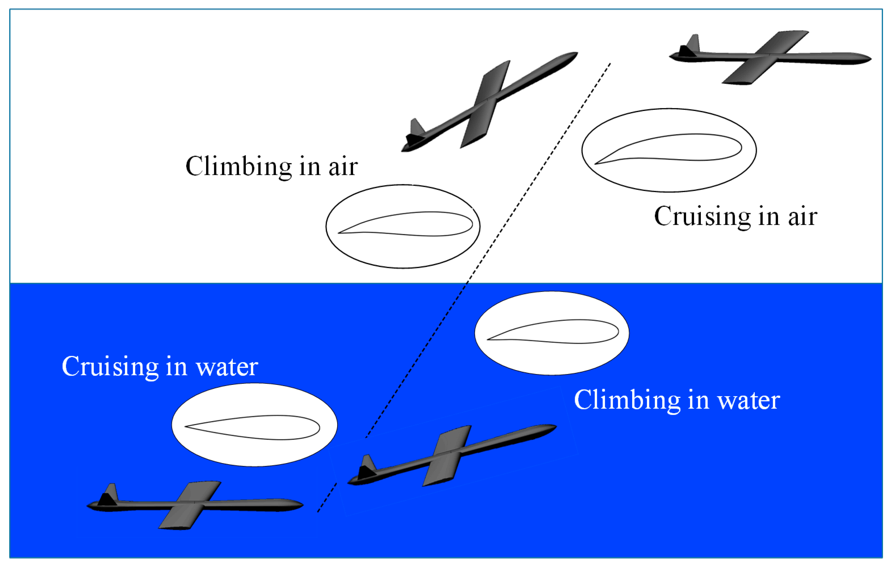
2.1. Proposed Working Process

Trans-domain aircrafts are required to adapt to different environments and media characteristics during their operation, and can typically be categorized into the following flight phases: (1) underwater cruise stage, (2) underwater climbing stage, (3) air cruise stage and (4) air cruise stage. The objective of this paper is to apply morphing aircraft technology to TDA design and to design a small trans-domain morphing UAV for marine environment monitoring and other purposes, as illustrated in Figure 1.
The initial task in the development of a trans-domain high-speed vehicle is the design of a multi-domain configuration that combines aerodynamic and hydrodynamic performance, as well as access to and from the water. The shape and structure of the TDA must be designed for both airborne performance and underwater navigation.
It is evident that water possesses greater density and viscosity than air; consequently, the drag experienced by a vehicle traversing through water is significantly greater than that through air. This necessitates precise control of the vehicle’s attitude and angle of attack to optimize hydrodynamic performance and mitigate flow resistance.
Reference [32] selected the NACA 0018 symmetrical airfoil, which has been shown to facilitate enhanced directional stability during cruise in water, while the larger maximum thickness (18%) of this airfoil provides greater structural strength in water to cope with larger hydrodynamic loads. However, the application of a single symmetric airfoil as a wing airfoil poses challenges in attaining the requisite aerodynamic characteristics for airborne flight. Consequently, this study aims to enhance the aerodynamic performance of the trans-domain vehicle in flight by employing a morphing trailing edge with active camber control. The working conditions are shown in Table 1. As shown in Figure 1, during underwater cruising, the wing should maintain a configuration that minimizes hydrodynamic drag. For the selected wing profile, the minimum drag condition occurs when the wing camber is zero.
During underwater climbing, however, the wing must generate additional lift, enabling the vehicle to ascend. In this case, the wing is required to undergo camber morphing to achieve an optimal lift-to-drag ratio under submerged conditions.
The distinct physical properties of water and air significantly affect the design and dynamic behavior of vehicles operating in underwater and aerial environments. As shown in Table 2, the key differences between the two media are summarized.

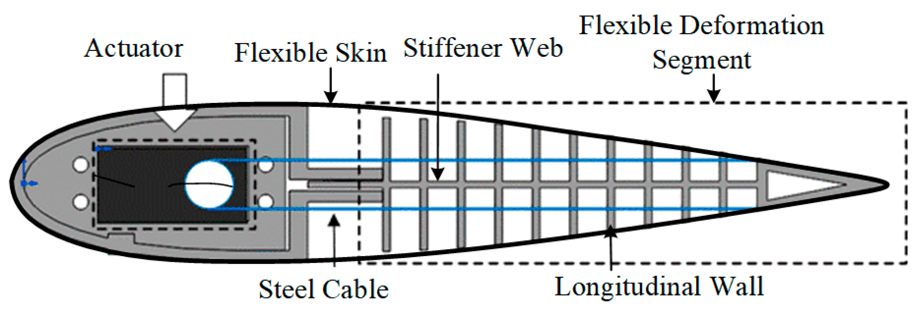
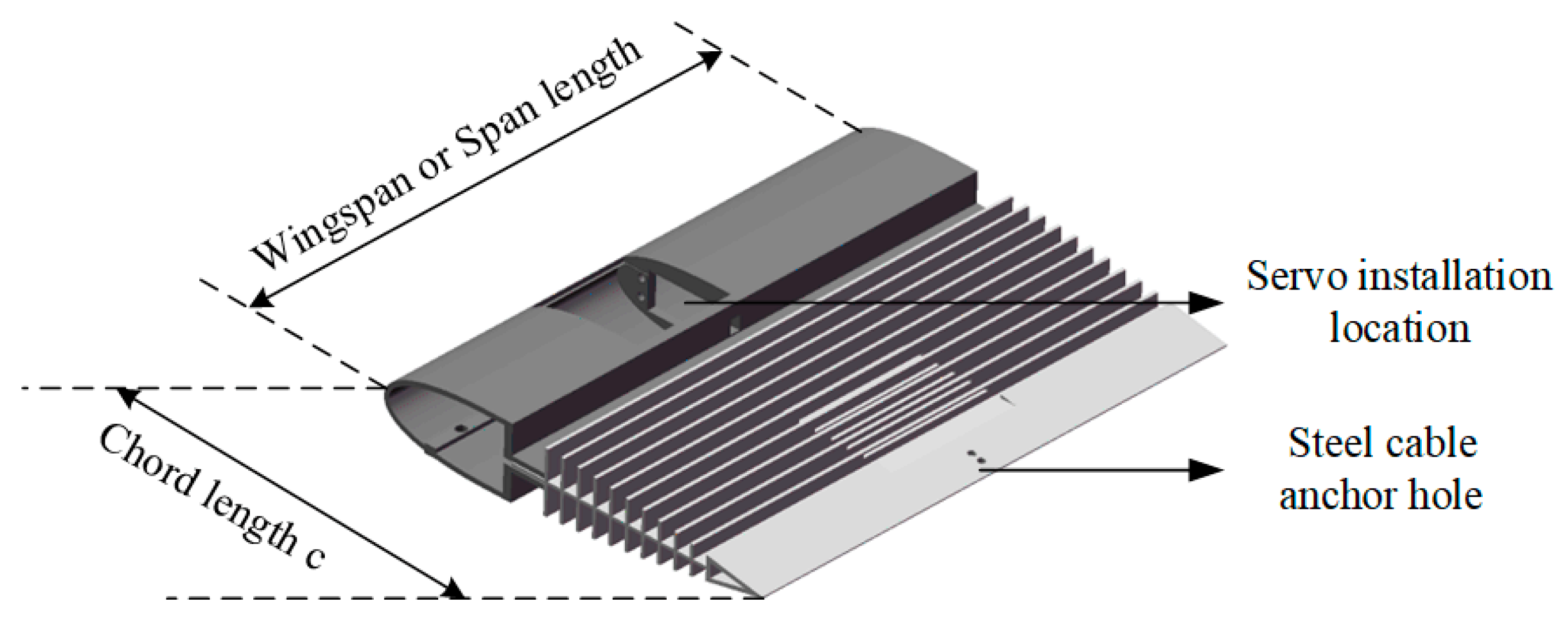
2.2. Conceptual Design of the Camber Morphing Wing

In order to meet the requirement of variable camber of the wing, this paper adopts the fishbone layout as the basic configuration of the wing. The deformable segment of the wing adopts a series of fishbone shapes as reinforcement structures, which can withstand aerodynamic loads while maintaining the continuity of the outer surface and enhancing the surface stiffness with flexible skin. Compared with the traditional discrete wing surface, this configuration can realize the change of wing camber and ensure the continuity and smoothness of the aerodynamic surface.
The structure model of the fishbone wing with variable camber is shown in Figure 2. The front end of the wing adopts rigid D-shaped beam design to ensure the stability and stiffness of the structure. The tail end is equipped with morphing rib array with graded stiffness to realize the deformation function of the wing. The fishbone flexible section consists of a slender web, which can be bent along its length, and a number of spar caps with variable thickness, which have an adjustable thickness design to meet different structural requirements. In addition, the fishbone variable bend wing is equipped with a pre-stretched flexible skin, which gives the overall structure the necessary elastic characteristics and a smooth aerodynamic surface.
In terms of the drive system, the design integrates a driver located in the D-shaped wing beam; by pulling the driving cable at the rear edge, the driving torque is effectively transmitted to the tail of the wing, so as to achieve the shape change of the wing. This driving method not only improves the response speed and accuracy of deformation but also ensures the mechanical stability and structural integrity of the wing during deformation.
In the theoretical analysis, the D-shaped wing beam is assumed to be a rigid body, since the driving loads mainly act on the flexible section. In the fishbone flexible section, the web located in the middle of the wing bears the main structural load-bearing task. As illustrated in Figure 3, the fishbone variant wing is founded upon a flexible structural design, comprising a spine web and a series of longitudinal walls attached to the web. Among them, the chordwise bending stiffness of the spine web is minimal, and only a small driving energy is required to achieve a substantial bending of the center chord. Through rational stiffness design, high stiffness is maintained to withstand aerodynamic loads, while low stiffness in the deformation direction is provided to meet the deformation needs.
The main design parameters of the variable camber wing are shown in Table 3. The morphing region spans 77.5% chordwise (0.225 ≤ x/c ≤ 1.0), and the total number of longitudinal walls in the flexible section is 20; the height of the spar cap is designed according to the variation of the wing shape, and the thickness of the spar cap thickness varies from 1.8 mm (root) to 2.2 mm (tip). The thickness of the web, as the main deformation component, was set at 2.5 mm, taking into account the need for flexible deformation.
Define the angular relationship at each position as the curvature of the fishbone wing changes, as shown in Figure 4.
From Figure 4, the deflection angle, which is used to represent the change of the camber, can be calculated by the following equation:
θ i = arctan ( Δ y i L i Δ x i )

3. Analysis of the Camber Morphing Wing Considering Fluid–Structure Interaction

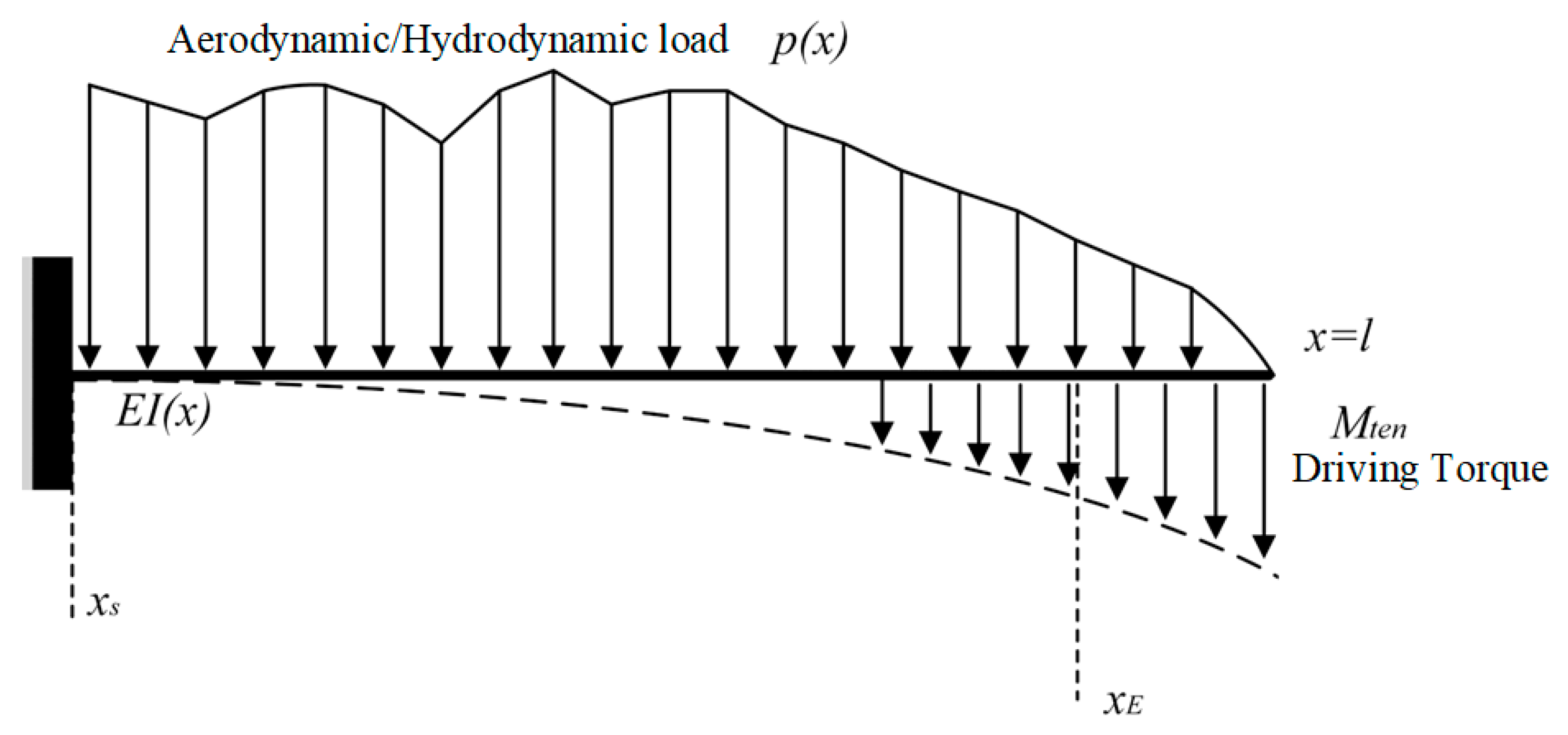
3.1. Modeling Method

The camber morphing process of the trailing edge of a TDA will be subjected to air and water loads in the air and underwater; thus, it must be deformed by the actuator in a bending manner; consequently, the deformation process of the camber morphing trailing edge constitutes a typical fully-coupled fluid–structure interaction problem.
In this paper, a fluid–structure coupling method is employed to calculate the actuation requirements under fluid loads and evaluate the potential flight performance with the deformation taken into account. The structural modeling is based on the Euler beam model and the fluid modeling is achieved with the vortex lattice method. The proposed structural model is also verified by comparing to the finite element method. The properties of the materials utilized in the wing structure are summarized in Table 4.
The structural model of the wing is established based on the ‘Euler–Bernoulli beam’ theory [33]. The flexible spine structure is regarded as a variable stiffness cantilever beam subjected to distributed moments, as illustrated in Figure 5.
d 2   d x 2 ( E I ( x ) d 2 W   d x 2 ) = p ( x )
where p(x) is the distributed loads of the fluid due to the water or air.
The pressure distribution along the wing surface is determined through the utilization of XFoil [34], with the data subsequently transferred to the structural model. The computational flowchart is illustrated in Figure 6.
In the iterative process, the aerodynamic load acting on the wing is transferred to the fishbone-type variable camber wing through the chord. The deformation of the variable camber wing under the joint action of the driving load and the aerodynamic load is then obtained. A comparison of the deformation results obtained in the previous step with the deformation results obtained in this step satisfies the convergence condition if the difference is less than 0.01%.
Calibration calculations are carried out for the structural model using the finite element method. The finite element model of the camber morphing wing is established based on the beam element. The findings of the simulation demonstrate that the equivalent beam model proposed aligns closely with theoretical analyses, particularly within the load range of 0–25 nm, where the discrepancy remains below 5%. This outcome serves to substantiate the reliability of the equivalent method.
In addition, a comparison of the results of the equivalent model, the original structure model and the theoretical analysis, as illustrated in Figure 7, reveals that the displacement error of the two is less than 8% within 25 nm. This verifies the applicability of the Euler–Bernoulli beam theory under the assumption of small deformation. However, when the load exceeds 30 nm, the theoretical analysis error reaches 12%, which is primarily attributable to the substantial geometrical nonlinear effect from the significant deformation. The equivalent model maintains a high degree of consistency with the original structure, underscoring its utility for engineering analysis within the range of small deformation.

3.2. Design Iteration

The modeling method outlined in Section 2.2 is employed to optimize the trailing edge camber of the TDA. The effects of external loads on structural deformation and driving force requirements are considered through the fluid–structure interaction method, facilitating the determination of airfoil shapes under various working conditions. The iteration design of the airfoil shape under the two states of water cruise and air cruise of the transmedia vehicle ensures high navigation efficiency when navigating in different media.
The iterative process of variable camber wing design is shown in Figure 8. According to the following process, the conceptual design and analysis of the fishbone trans-domain morphing camber wing is carried out; the modeling of the morphing camber wing is completed; the structural iteration and design are carried out considering the fluid–structure coupling; and based on the finite element calibration, the scaled-down test samples are processed and the underwater and airborne morphing tests are carried out.
The reference [35] was consulted, and the working conditions of the transmedia vehicle were determined as shown in Table 5. In addition, during the optimization process, the driving torque range was set at 0–25 nm and parasite drag coefficient is 0.02.
The coupled fluid–structure analysis is implemented by calling XFoil through MATLAB (version 2019B), and the optimal design is carried out for the two working conditions of underwater cruise and air cruise, respectively, by combining the deformation characteristics of the variable camber airfoil. XFoil version 6.99 is used for the analysis.
(1)
Objective
During underwater cruising, the higher density of water relative to air ensures the vehicle’s lift is guaranteed when a symmetrical airfoil is employed and a specific angle of attack is maintained. Consequently, with the objective of minimizing the drag coefficient, the fluid resistance of the deformed wing at a constant flow rate is calculated by XFoil. However, in the air cruise condition, the symmetric airfoil is inadequate in maintaining the flight state. Therefore, the airfoil must be adjusted to enhance the lift-to-drag ratio to ensure the airborne flight state. Consequently, the aerodynamic performance of the deformed airfoil at a fixed angle of attack is analyzed by XFoil with the optimization objective of maximizing the lift-to-drag ratio for air cruise.
(2)
Variables
In the optimized design, the variable is the wing camber, which is varied in the calculations by altering the driving torque. The driving moments are taken in the range of 0–25 nm, with an interval of 1 nm, resulting in a total of 26 groups of discrete cases. Each moment value corresponds to a specific wing curvature deformation scheme, then a group of wing camber value is captured, and the deformed wing geometry is calculated by the equivalent beam finite element model.
(3)
Constrains
The fundamental constraint pertains to the convergence of the XFoil analysis. In the event that the wing deformation corresponding to a specific driving moment results in the dispersion of the flow field calculation (e.g., severe boundary layer separation or mesh distortion), the case is to be excluded. Furthermore, the extent of wing deformation is required to satisfy the geometric continuity requirement, which averts sudden changes in local curvature.
(4)
Results
Condition 1: Underwater cruising
As shown in Figure 9, Figure 9a represents the wing profile and Figure 9b represents the pressure coefficients on the upper and lower surfaces of the wing. In the absence of a driving moment, the drag coefficient of the wing shape is at its lowest point in comparison to the initial state. Concurrently, the driving moment is zero, the wing deformation is zero, the drag coefficient is constant, the lift-to-drag ratio remains constant, the underwater cruise state is maintained, and the wing shape remains symmetrical.
Condition 2: Underwater Climbing
As shown in Figure 10, the airfoil changes under the action of the bending moment, and the bending moment required at the maximum lift-to-drag ratio in the water as well as the pressure coefficients on the upper and lower surfaces at this point are calculated. The optimization results demonstrate that when the driving torque is 16 nm, the deformation angle is 5.08°. The lift-to-drag ratio reaches a peak of 38.46.
Condition 3: Air Cruise
The corresponding bending moment and airfoil results for air cruise are shown in Figure 11. The wing is deflected downwards in order to maximize the lift-to-drag ratio in the airborne cruise state, as the optimization results demonstrate. The drag coefficient of the wing is the lowest when the driving torque is 0, as compared to the initial state. During air flight, the driving torque is 22 nm and the deformation angle is 8.8°. The lift-to-drag ratio achieves a maximum value of 33.56. The optimization results are tabulated in Table 6.
Following the active camber morphing, the leading-edge curvature increases significantly, altering the surface pressure distribution and thereby enhancing boundary layer attachment. This is particularly beneficial under low-to-moderate Reynolds numbers, where the increased front-end camber helps to delay flow separation and mitigate stall behavior, resulting in a higher critical angle of attack and improved maximum lift coefficient. Moreover, the camber-induced geometric change modifies the wake characteristics, effectively reducing both induced drag and pressure drag components. The NACA0018 airfoil has a lift to drag ratio of 20.4 for underwater climbing without deformation. Air cruise has a lift to drag ratio of 15.4. From the data in Table 6, the lift to drag ratio resulting in a significant aerodynamic improvement
According to the iteration results, it can be found that due to the different targets to be considered when the trans-domain aircraft is sliding underwater and, in the air, the requirements for its shape are also different. By changing the camber trailing edge, the wing trailing edge can be changed to meet the needs of navigation in different media.
In this study, a fishbone wing structure with variable camber was adopted to realize the camber change of the trailing edge of the wing, as shown in Figure 12. The wing front end adopts rigid D-shaped beam design to ensure the stability and stiffness of the structure. In the driving system, the servo steering machine is used to pull the driving cable at the rear edge, and the driving torque is effectively transmitted to the tail end of the wing, so as to achieve the shape change of the wing. Other design parameters are consistent with those in Section 2.
The finite element analysis is carried out. A 10-node tetrahedral cell was used, dividing a total of 9906 cells.
According to the iterative calculation results, the surface wing surface receives the maximum pressure during water climbing. Secondly, when cruising in the air, the wing needs to have a maximum Cambensy change of 8.8°, and the aerodynamic load and internal drive displacement are multiplied by the safety factor of 1.5 as the load and displacement boundary conditions. This confirms that the material can guarantee sufficient stiffness under external loads, and that the material does not fail when the wing is driven from the inside to undergo maximum bending deformation.
Finite element analysis is conducted to find the von Mises stress distribution and displacement of the trailing edge structure, as illustrated in Figure 13 and Figure 14. Detailed model was built using solid elements and one end of the Fish-BAC spine structure is clamped and actuation moments are applied to deflect the trailing edge.
According to the simulation results, the maximum deformation of the fishbone wing with variable bending due to aerodynamic load is 1.5 mm, which is negligible compared with the overall wing size. In addition, the maximum Mises stress of the material is 9.4 MPa, which is less than the allowable force of the material at the position with the greatest change in bending. Therefore, in terms of stiffness and strength and driving deformation ability, the selected material is in line with the requirements and can be tested.

4. Experimental Demonstration

4.1. Demonstrator Preparation

The experimental arrangement is as follows: an optical-grade acrylic water tunnel (test section 0.4 × 0.8 × 1.5 m3) with refractive index matching (n = 1.33) is used to establish an experimental environment in water, and the changes of wing curvature in air and water are, respectively, tested. The experimental diagram is shown in Figure 15. In this experiment, the leading edge of the wing is fixed and the test mark is affixed to the deformable position. The change of wing curvature is controlled by rudder output, and the change of mark position is recorded by measuring device.
As demonstrated in Figure 16, the 3D printing technique was employed to fabricate the test prototype utilizing a 1:5 scale-down model, with the mounting position of the rudder and the holes for connecting the leading and trailing edges of the wing being reserved.
In order to ensure the stability of the base, additional counterweight is added to improve the stability of the base, and the trailing edge of the placed wing is unstable during the deformation process.
Taking the variable camber test under the water surface as an example, the wing installation is shown on the right side of Figure 16. At the same time, the steering gear used is an insulated steering gear, which can operate normally in water. Steering gear parameters are shown in Table 7.
The servo motor is controlled via host computer software to achieve precise rotation angle adjustment. As illustrated in Figure 17, the servo torque is transmitted through steel cables to generate the bending moment required for camber variation of the wing. The configuration in which the steel cable connection is tangent to the servo output arm corresponds to the nominal neutral (horizontal) position of the wing.
To ensure smooth and continuous camber morphing, a pre-tension angle of ±30° is applied to the upper and lower cables, respectively. Specifically, when connecting the upper cable, the servo horn is pre-rotated by 15° in the reverse direction; the same principle applies to the lower cable. This configuration maintains a certain level of pre-tension on both sides, enabling stable and continuous bidirectional deformation of the wing structure.
In accordance with Froude’s similarity criterion, the formula for calculating the scaled model driving moment is as follows:
u p g p L p = u m g p L m = F r
where u is the flow velocity; g is the gravitational acceleration; L is the characteristic length; Fr is the Froude number; and p and m are subscripts representing the prototype and model, respectively, since both prototype and model are in the same gravity field. Therefore, the model length scale is selected according to Froude’s similarity criterion.
L r = L p / L m
Thus, the scaled down model drive torque is 1/125 of the prototype and the drive torque is 0.176 nm.
According to the calculation of driving torque in Section 3, the locked-rotor torque provided by the steering gear and the variable camber demand of the compound wing with driving stroke can be seen. The maximum driving torque is 4.74 nm, which is much higher than the calculated 0.176 nm. With the increase of wing curvature, the driving lever also increases, and the torque generated by the steering gear is sufficient to deform the wing to the specified position.
To test the deformation ability of the fishbone wing, a Digital Image Correlation (DIC) test system is used to test the deformation ability of the prototype of the trans-domain aircraft. Figure 17 illustrates the leading-edge structure of the wing and the fishbone structure, which includes space for the driver installation and the wing fixing structure at the leading edge. Figure 4 in Section 2.2 shows the definition of Angle of camber change, which is the Angle between the trailing edge point before and after deformation and the starting point of varying camber is taken as the Angle of camber change. The DIC test method in this test was designed according to the definition of curvature, as shown in Figure 13. Three marked dots were pasted on one side of the fishbone wing, and the DIC test software Haytham (https://www.haytham.com.cn, accessed on 25 February 2025) could automatically identify the position of the marked points and use each frame image for real-time tracking to calculate the displacement of each marked point.

4.2. Results and Discussions

As illustrated in Figure 18, the images captured by the DIC camera during the on- and off-surface airfoil variable curvature tests (initial state, trailing edge maximum upward deflection vs. trailing edge maximum downward deflection states, for example) are presented.
The calculated bending values of the fishbone wing at each monitoring point in the above-surface and below-surface variable bending tests were obtained as shown in Figure 19a,b.
The displacement of the marked points is converted to obtain the value of the change of bending when the fishbone wing is deformed in water and in air (see Figure 19). Monitoring Point 1 does not move during the deflection of trailing edge and can be considered as the starting point to calculate the change of curvature. And the actual curvature change of the wing is the value obtained at Monitoring Point 3. According to the DIC results, the maximum upward deflection angle of the trailing edge of the wing is approximately 10.59° when it is above the water, and the maximum downward deflection angle is about 9.70°. When the wing structure is submerged by the water, the trailing edge can still reach the maximum upward deflection angle of approximately 10.81°, with the maximum downward deflection angle around 9.49°, which preliminarily satisfies the design requirements of the design iteration results in Section 3.2. The detailed results are summarized in Table 8.
While the current actuation system based on steel cable transmission achieves the desired morphing deformation in both air and water, certain limitations are anticipated in dynamic or real-time scenarios. Issues such as cable slack, mechanical hysteresis and response delay during the switch between tension and release modes may impair precise control, especially under varying environmental conditions. These behaviors are inherent to flexible transmission systems and are further exacerbated in aqueous environments due to increased viscous damping. Future work should consider integrating real-time sensing and feedback mechanisms to compensate for such effects. Additionally, alternative actuation materials or mechanisms with reduced hysteresis and higher responsiveness could further enhance morphing performance in cross-medium applications.

5. Conclusions

In the current study, the Fish-BAC camber morphing wing is designed as the trans-domain aircraft and the following conclusions can be made:
  • A conceptual design of the trans-domain aircraft is proposed, which is based on curvature change generated by the camber morphing wing. And the aircraft is supposed to maintain good performance both in the air and in the water.
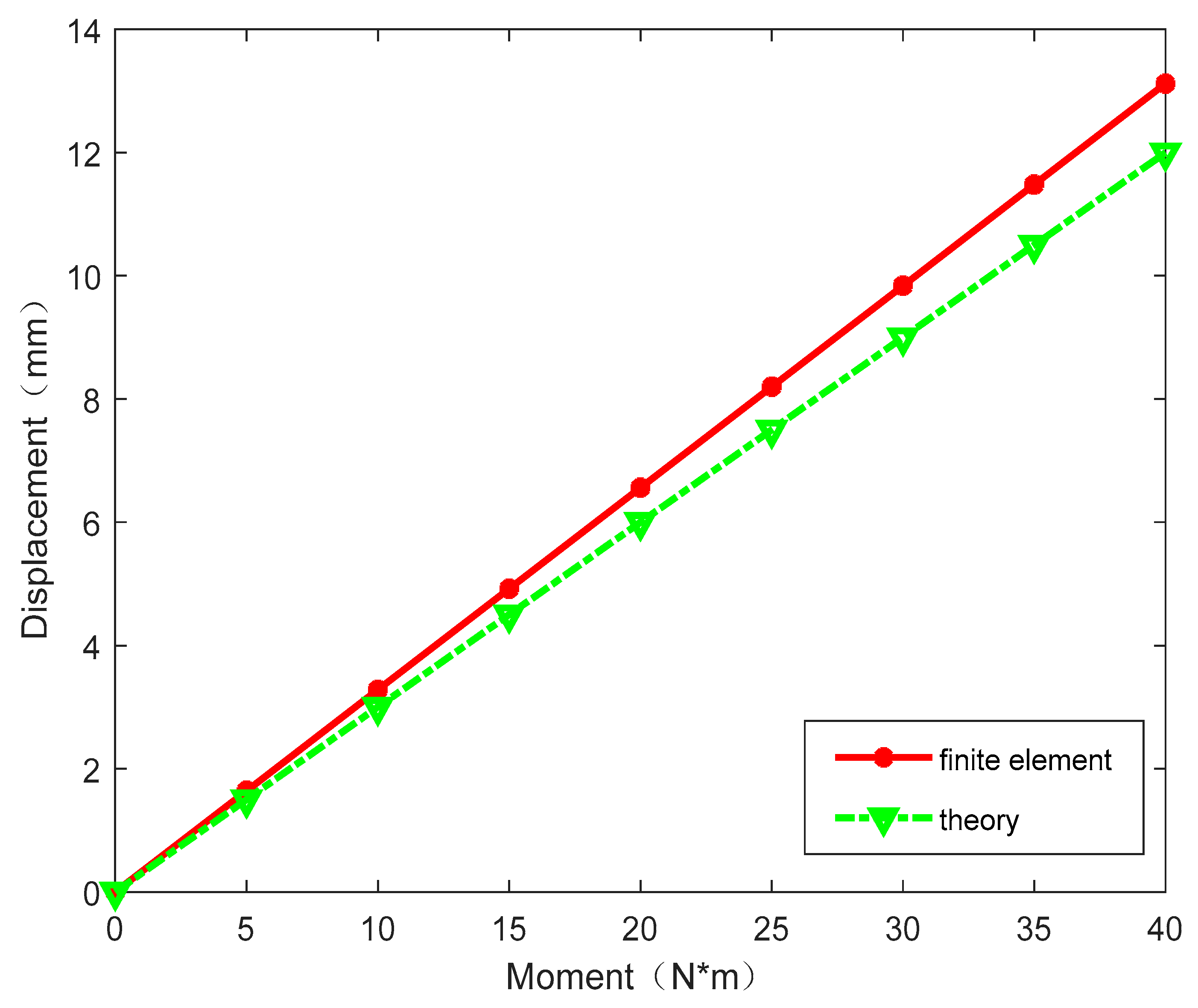
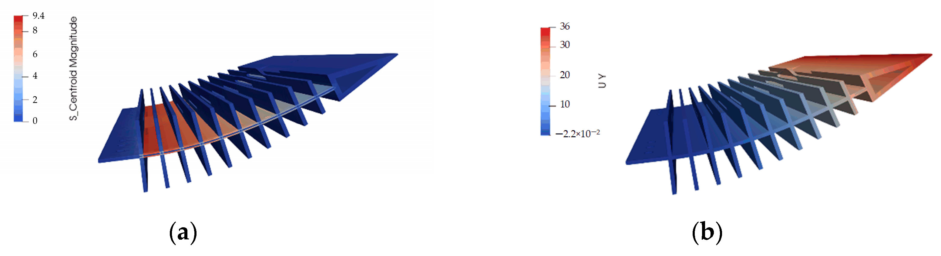
  • Structural and aerodynamic models are made to perform the fluid–structure interaction analysis based on the Euler beam theory and the vortex lattice method, and the modeling method is verified by comparing with the results from finite element method.
  • The design iteration is applied to find the proper camber change in different working conditions, considering the working process from the water to the air using the fluid–structure interaction analysis.
  • A demonstration model is made to verify the camber change, both in the air and in the water, which preliminarily validates the proposed concept.
The future work will focus on the comprehensive optimization of the camber morphing wing and more experimental work will be performed considering more working conditions and to explain the fluid mechanism due to morphing. The current study is still at the conceptual level, and more work will be performed to develop the system from the perspective of the morphing structure, actuation, control and highlight the performance increase by morphing.

Author Contributions

Conceptualization, M.W., M.X. and X.S.; Methodology, M.W., M.X., X.S. and C.W.; Software, C.W.; Validation, M.W., Z.L., Y.Z. and Q.H.; Formal analysis, M.W., Z.L., Y.Z., C.W. and Q.H.; Investigation, Y.Z.; Data curation, Z.L.; Writing—original draft, M.W., Z.L. and Y.Z.; Writing—review & editing, M.X., X.S., Z.L., C.W. and Q.H.; Project administration, M.X. and X.S.; Funding acquisition, M.X. All authors have read and agreed to the published version of the manuscript.

Funding

This research received no external funding.

Data Availability Statement

The original contributions presented in this study are included in the article. Further inquiries can be directed to the corresponding author.

Conflicts of Interest

The authors declare no conflict of interest.

References

  1. Feng, J.; Hu, J.; Qi, D. Study on development needs and key technologies of air-water trans-media vehicle. J. Air Force Eng. Univ. 2019, 20, 8–13. [Google Scholar]
  2. Ji, W.; Qi, X.; Li, D. Operational application and effectiveness evaluation of reentry cross-medium unmanned aerial vehicles. Electron. Opt. Control. 2022, 29, 38–42. [Google Scholar]
  3. Zeng, Z.; Lyu, C.; Bi, Y.; Jin, Y.; Lu, D.; Lian, L. Review of hybrid aerial underwater vehicle: Cross-domain mobility and transitions control. Ocean Eng. 2022, 248, 110840. [Google Scholar] [CrossRef]
  4. Yao, G.; Li, Y.; Zhang, H.; Jiang, Y.; Wang, T.; Sun, F.; Yang, X. Review of hybrid aquatic-aerial vehicle (HAAV): Classifications, current status, applications, challenges and technology perspectives. Prog. Aerosp. Sci. 2023, 139, 100902. [Google Scholar] [CrossRef]
  5. Nicholson, J.W.; Healey, A.J. The Present State of Autonomous Underwater Vehicle (AUV) Applications and Technologies. Mar. Technol. Soc. J. 2008, 42, 44–51. [Google Scholar] [CrossRef]
  6. Yang, X.; Wang, T.; Liang, J.; Yao, G.; Liu, M. Survey on the novel hybrid aquatic–aerial amphibious aircraft: Aquatic unmanned aerial vehicle (AquaUAV). Prog. Aerosp. Sci. 2015, 74, 131–151. [Google Scholar] [CrossRef]
  7. Yinggu, Z.; Guoliang, F.; Jianqiang, Y. Modeling longitudinal aerodynamic and hydrodynamic effects of a flying boat in calm water. In Proceedings of the 2011 IEEE International Conference on Mechatronics and Automation, Beijing, China, 7–10 August 2011; pp. 2039–2044. [Google Scholar]
  8. Stewart, W.; Weisler, W.; MacLeod, M.; Powers, T.; Defreitas, A.; Gritter, R.; Anderson, M.; Peters, K.; Gopalarathnam, A.; Bryant, M. Design and demonstration of a seabird-inspired fixed-wing hybrid UAV-UUV system. Bioinspir. Biomim. 2018, 13, 056013. [Google Scholar] [CrossRef] [PubMed]
  9. Weisler, W.; Stewart, W.; Anderson, M.B.; Peters, K.J.; Gopalarathnam, A.; Bryant, M. Testing and Characterization of a Fixed Wing Cross-Domain Unmanned Vehicle Operating in Aerial and Underwater Environments. IEEE J. Ocean. Eng. 2017, 43, 969–982. [Google Scholar] [CrossRef]
  10. Stewart, W.; Weisler, W.; Anderson, M.; Bryant, M.; Peters, K. Dynamic Modeling of Passively Draining Structures for Aerial–Aquatic Unmanned Vehicles. IEEE J. Ocean. Eng. 2020, 45, 840–850. [Google Scholar] [CrossRef]
  11. Li, H.; Lu, K.; Chen, Y.; Zhu, M.; Lu, P.; Duan, H. Structure design of a novel bionic water-air cross-domain vehicle. J. Unmanned Undersea Syst. 2022, 30, 726–732. [Google Scholar]
  12. Yang, X.B.; Liang, J.H.; Wen, L.; Wang, T.M. Research status of water-air amphibious trans-media unmanned vehicle. Robot 2018, 40, 102–114. [Google Scholar]
  13. Siddall, R.; Kennedy, G.; Kovac, M. High-power propulsion strategies for aquatic take-off in robotics. In Proceedings of the 50th International Symposium on Robotics Research, Munich, Germany, 20–21 June 2018; pp. 5–20. [Google Scholar]
  14. Siddall, R.; Kovac, M. Fast aquatic escape with a jet thruster. IEEE/ASME Trans. Mechatron. 2017, 22, 217–226. [Google Scholar] [CrossRef]
  15. Siddall, M.; Kovac, M. Launching the AquaMAV: Bioinspired design for aerial-aquatic robotic platforms. Bioinspir. Biomim. 2014, 9, 031001. [Google Scholar] [CrossRef] [PubMed]
  16. Siddall, R.; Kovac, M. A water jet thruster for an aquatic micro air vehicle. In Proceedings of the 2015 IEEE International Conference on Robotics and Automation (ICRA), Seattle, WA, USA, 26–30 May 2015; pp. 3979–3985. [Google Scholar]
  17. Chen, Y. The Design and Analysis of Fluid Dynamic Characteristics for Submersible Unmanned Aerial Vehicle; Nanjing University of Aeronautics and Astronautics: Nanjing, China, 2019. [Google Scholar]
  18. Ma, Z.; Feng, J.; Yang, J. Research on vertical air–water trans-media control of hybrid unmanned aerial underwater vehicles based on adaptive sliding mode dynamical surface control. Int. J. Adv. Robot. Syst. 2018, 15, 1729881418770531. [Google Scholar] [CrossRef]
  19. Lu, D.; Xiong, C.; Zeng, Z.; Lian, L. A multimodal aerial underwater vehicle with extended endurance and capabilities. In Proceedings of the 2019 International Conference on Robotics and Automation (ICRA), Montreal, QC, Canada, 20–24 May 2019; pp. 4674–4680. [Google Scholar]
  20. Miller, E.J.; Lokos, W.A.; Cruz, J.; Crampton, G.; Stephens, C.A.; Kota, S.; Ervin, G.; Flick, P. Approach for structurally clearing an adaptive compliant trailing edge flap for flight. In Proceedings of the Society of Flight Test Engineers International Annual Symposium, Lancaster, CA, USA, 14–17 September 2015. [Google Scholar]
  21. Livne, E.; Precup, N.; Mor, M. Design, construction, and tests of an aeroelastic wind tunnel model of a variable camber continuous trailing edge flap (VCCTEF) concept wing. In Proceedings of the 32nd AIAA Applied Aerodynamics Conference, Atlanta, GA, USA, 16–20 June 2014; p. 2442. [Google Scholar]
  22. Precup, N.; Mor, M.; Livne, E. The design, construction, and tests of a concept aeroelastic wind tunnel model of a high-lift variable camber continuous trailing edge flap (HL-VCCTEF) wing configuration. In Proceedings of the 56th AIAA/ASCE/AHS/ASC Structures, Structural Dynamics, and Materials Conference, Kissimmee, FL, USA, 5–9 January 2015; p. 1406. [Google Scholar]
  23. Woods, B.K.; Friswell, M.I. Preliminary investigation of a fishbone active camber concept. In Proceedings of the ASME Conference on Smart Materials, Adaptive Structures and Intelligent Systems, Stone Mountain, GA, USA, 19–21 September 2012; pp. 555–563. [Google Scholar]
  24. Woods, B.K.; Friswell, M.I. Fluid-structure interaction analysis of the fish bone active camber mechanism. In Proceedings of the 54th AIAA/ASME/ASCE/AHS/ASC Structures, Structural Dynamics, and Materials Conference, Boston, MA, USA, 8–11 April 2013; p. 1908. [Google Scholar]
  25. Lu, J.; Song, W.; Cao, R.; Liang, Y.; Feng, L.; Qi, Y. Airfoil Preference and Adjustable Camber Impact Analysis for Trans-Medium Fixed-Wing Vehicles. J. Unmanned Undersea Syst. 2025, 33, 113–123. [Google Scholar]
  26. Bousquet, G.; Izraelevitz, J.; Triantafyllou, M. Bioinspired Design of Dual Aerial-Aquatic Vehicles for Ocean Sampling; Research Poster; MIT Towing Tank Lab: Cambridge, MA, USA, 2024. [Google Scholar]
  27. Lock, R.J.; Vaidyanathan, R.; Burgess, S.C. Development of a biologically inspired multi-modal wing model for aerial-aquatic robotic vehicles. In Proceedings of the 2010 IEEE/RSJ International Conference on Intelligent Robots and Systems, Taipei, Taiwan, 18–22 October 2010; pp. 3404–3409. [Google Scholar]
  28. Lock, R.J.; Vaidyanathan, R.; Burgess, S.C.; Loveless, J. Development of a biologically inspired multi-modal wing model for aerial-aquatic robotic vehicles through empirical and numerical modelling of the common guillemot, Uria aalge. Bioinspir. Biomim. 2010, 5, 046001. [Google Scholar] [CrossRef] [PubMed]
  29. Zyga, L. Seabird’s Morphing Wings Inspire Design for Robots that Can Both Fly and Swim. Available online: https://phys.org/news/2010-11-seabird-morphing-wings-robots.html (accessed on 1 October 2023).
  30. Carossa, G.M.; Ricci, S.; De Gaspari, A.; Liauzun, C.; Dumont, A.; Steinbuch, M. Adaptive trailing edge: Specifications, aerody-namics, and exploitation. In Smart Intelli-gent Aircraft Structures (SARISTU): Proceedings of the Final Project Conference; Woelcken, P.C., Papadopoulos, M., Eds.; Springer International Publishing: Cham, Switzerland, 2016; pp. 143–158. [Google Scholar]
  31. Kuzmina, S.; Ishmuratov, F.; Zichenkov, M.; Chedrik, V.; Amiryants, G.A.; Kulesh, V.; Malyutin, V.; Chedrik, A.; Timokhin, V.; Shalaev, S.; et al. Wind tunnel testing of adaptive wing structures. In Morphing Wing Technologies; Concilio, A., Dimino, I., Lecce, L., Eds.; Butterworth-Heinemann: Oxford, UK, 2017; pp. 713–755. [Google Scholar]
  32. Concilio, A.; Dimino, I.; Pecora, R. SARISTU: Adaptive Trailing Edge Device (ATED) design process review. Chin. J. Aeronaut. 2021, 34, 187–210. [Google Scholar] [CrossRef]
  33. Huang, K.; Zhang, J.Y.; Wang, C. Equivalent structure model of fish bone active camber morphing concept and analysis of aeroelastic characteristics. J. Nanjing Univ. Aeronaut. Astronaut. 2024, 56, 516–525. [Google Scholar]
  34. XFOIL Help Documentation. Available online: https://web.mit.edu/drela/Public/web/xfoil/ (accessed on 1 July 2024).
  35. Wang, Z.H.; Li, Y.; Wang, A.B.; Wang, X. Flying wing underwater glider: Design, analysis, and performance prediction. In Proceedings of the 2015 International Conference on Control, Automation and Robotics, Singapore, 20–22 May 2015; pp. 74–77. [Google Scholar]
Figure 1. Trans-domain aircraft concept.
Machines 13 00428 g001
Figure 2. Schematic diagram of a fishbone variable camber wing structure.
Machines 13 00428 g002
Figure 3. Definition of variable camber wing parameters.
Machines 13 00428 g003
Figure 4. Trailing edge camber definition.
Machines 13 00428 g004
Figure 5. Schematic of the beam model.
Machines 13 00428 g005
Figure 6. Pneumatic profile calculation process.
Machines 13 00428 g006
Figure 7. Comparison of theoretical and finite element results.
Machines 13 00428 g007
Figure 8. Variable camber wing design process.
Machines 13 00428 g008
Figure 9. Iteration of airfoil shape and pressure coefficient distribution for underwater cruising. (a) Airfoil; (b) pressure coefficient. The red and blue lines represent the upper and lower surfaces of the airfoil, respectively.
Machines 13 00428 g009
Figure 10. Iteration of airfoil shape and pressure coefficient distribution for underwater climb. (a) Airfoil; (b) pressure coefficient. The red and blue lines represent the upper and lower surfaces of the airfoil, respectively, while the green line indicates the bending moment.
Machines 13 00428 g010
Figure 11. Iteration of airfoil shape and pressure coefficient distribution for air cruise. (a) Airfoil; (b) pressure coefficient. The red and blue lines represent the upper and lower surfaces of the airfoil, respectively, while the green line indicates the bending moment.
Machines 13 00428 g011
Figure 12. Schematic diagram of a fishbone-type variable camber wing structure.
Machines 13 00428 g012
Figure 13. Water Climbing Status. (a) Mises stress; (b) Displacement magnitude.
Machines 13 00428 g013
Figure 14. Material Rigidity under Maximum External Load. (a) Mises stress; (b) Displacement magnitude.
Machines 13 00428 g014
Figure 15. Schematic diagram of the experiment.
Machines 13 00428 g015
Figure 16. Physical model of a fishbone wing with variable camber.
Machines 13 00428 g016
Figure 17. Driving torque calculation model.
Machines 13 00428 g017
Figure 18. DIC camera captures images.
Machines 13 00428 g018
Figure 19. Curvature change curve. (a) Underwater; (b) In the air.
Machines 13 00428 g019
Table 1. Working conditions.
Working ConditionsCruising SpeedAngle of Attack RangeReynolds Number
Underwater Cruise0.5 m/s–5 m/s[−5°,5°]1 × 106–2 × 10
Underwater Climbing0.5 m/s–5 m/s[0°,10°]1 × 106–2 × 10
Air Cruise30 m/s–50 m/s[0°,10°]2 × 107–3.4 × 10⁷
Table 2. Differences in Media.
PropertyWater (Liquid)Air (Gas)Ratio (Water/Air)
Density998 kg/m31.204 kg/m3~829:1
Dynamic Viscosity1.002 × 10−3 Pa·s1.813 × 10−5 Pa·s~55:1
Kinematic Viscosity1.004 × 10−6 m2/s1.516 × 10−5 m2/s~0.066:1
Specific Heat (Cp)4182 J/(kg·K)1005 J/(kg·K)~4.16:1
CompressibilityIncompressibleaffected by speed
Table 3. Parameters of fishbone type variable camber wing.
ParametersValue
AirfoilNACA 0018
Chord length c200 mm
Spread b300 mm
Deformation start position22.5%
Number of vertical walls n20
Thickness of longitudinal wall2 mm
Web thickness2 mm
Table 4. Material properties.
Material ParametersValue
Density1.14 g·cm−3
Young’s modulus2200 MPa
Poisson’s ratio0.4
Yield stress90 MPa
Table 5. Simulated condition.
Working ConditionsAngle of AttackCruising SpeedMedia DensityReynolds Number
Underwater Cruise3.4 m/s1000 g·cm−32 × 106
Underwater Climb3.4 m/s1000 g·cm−32 × 106
Air Cruise34 m/s1.225 g·cm−33 × 107
Table 6. Iteration results analysis.
Working
Conditions
Variant (Driving Torque)TargetValueTrailing Edge
Deformation
Underwater Cruise0 nmmin Cd
Underwater Climbing16 nmmax L/D38.465.08°
Air Cruise22 nmmax L/D33.568.8°
Table 7. Servo Parameter List.
ModelsValues
Voltage rangeDC 5–8.4 v
Blocking torque60 kg~8.4 v
Distance270°
Size23.5 × 8 × 16.8 mm
Table 8. Comparison of optimization and test results.
Working ConditionsTarget AngleTest Angle (Down)Test Angle (Up)
Underwater cruise
Underwater Climbing5.08°9.49°10.81°
Air cruise8.8°9.70°10.59°
Disclaimer/Publisher’s Note: The statements, opinions and data contained in all publications are solely those of the individual author(s) and contributor(s) and not of MDPI and/or the editor(s). MDPI and/or the editor(s) disclaim responsibility for any injury to people or property resulting from any ideas, methods, instructions or products referred to in the content.

