Article

Modeling and Dynamic Characteristic Analysis of a Rigid–Flexible Coupling Multi-Stage Gear Transmission System for High-Power-Density Diesel Engines

1
School of Mechanical Engineering, Beijing Institute of Technology, Beijing 100081, China
2
China North Engine Research Institute, Tianjin 300400, China
*
Authors to whom correspondence should be addressed.
Machines 2025, 13(5), 416; https://doi.org/10.3390/machines13050416
Submission received: 24 March 2025 / Revised: 1 May 2025 / Accepted: 6 May 2025 / Published: 15 May 2025
(This article belongs to the Section Machine Design and Theory)

Abstract

:
To investigate the mechanisms of unexpected failures in a multi-stage gear transmission system under a relatively low load, a rigid–flexible coupled multi-body dynamics model with 10 spur gears and 12 helical gears is established. The dynamic condensation theory is applied to improve computational efficiency. The construction of this model incorporates critical nonlinear factors, ensuring high precision and reliability. Based on the proposed model, four critical dynamic parameters, including acceleration, mesh stiffness, dynamic transmission error, and vibration displacement, are analyzed. This research systematically reveals the nonlinear dynamic mechanism under the multi-gear coupling effect. The spectrum of the gears exhibits prominent low-frequency peaks at 320 Hz and 750 Hz. Notably, alternate load-dominated gears show a shift in prominent low-frequency peaks. The phenomenon of marked oscillations in mesh stiffness suggests a potential risk of localized weakening in the system’s load-carrying capacity. Critically, alternating torques induce periodic double-tooth contact regions in the gear at specific time points (0.115 s and 0.137 s), which are identified as critical factors leading to gear transmission system failures. The variation characteristics of the dynamic transmission error (DTE) demonstrate that the DTE is strongly correlated with the meshing state. The analysis of vibration displacement further indicates that the alternating external loads are the dominant excitation source of vibrations, noise, and failures in the gear transmission system.

1. Introduction

1.1. Background

The gear transmission system, characterized by its compact structure, high transmission efficiency, and high service life, has found extensive applications across multiple domains, including automotive, marine, and aerospace engineering. The mechanisms of vibration and noise generation in a gear transmission system are highly complex, particularly for multi-stage gear transmission mechanisms. Unexpected failures have been encountered in high-power-density diesel-engine multi-stage gear transmission systems under relatively low load conditions during actual operation. Therefore, the development of accurate multi-stage gear models and the analysis of gear dynamic characteristics hold significant academic value and practical importance for a comprehensive investigation into the fatigue mechanisms of gears.

1.2. Literature Review

Accurate gear models serve as the foundation for the analysis of gear dynamic characteristics. Numerous studies have been conducted by scholars in the fields of gear modeling and dynamic analysis. The study of the single-stage gear model constitutes the foundation of all gear-related research, and researchers have achieved a substantial body of work in the modeling and analysis of single-stage gear models. The nonlinear gear model is widely used in the investigation of dynamic gear behaviors [1,2,3,4,5,6]. Li et al. [7] established a gear dynamic model with multiple degrees of freedom that comprehensively considers both the tribological and dynamic characteristics of the gear meshing process. Mohammed et al. [8] developed gear dynamic models with six, eight, twelve, and reduced eight degrees of freedom. These studies showed that gear dynamic models with multiple degrees of freedom are more reliable for investigating gear fault mechanisms. The accurate characteristics of nonlinear phenomena are also critical requirements for a high-precision model. Xu et al. [9] established a new gear contact dynamics model with nonlinear characteristics and compared it with the lumped parameter method and experimental method. Xi’an Jiaotong University [10] introduced viscous damping into a gear pair model with a single degree of freedom and identified that time-varying mesh stiffness and backlash are significant factors contributing to the nonlinear behavior of the gear system. A great deal of research has been conducted to establish the limitations of lumped parameter models. Li et al. [11] established a new spur gear dynamic model based on gear compatibility conditions. The results show that traditional models lose significant nonlinear characteristics in high-speed regions. Tian et al. [12] proposed a dynamic model of the spur gear system. Considering gear backlash and bearing clearance, the complicated nonlinear behaviors of the spur gear system are revealed, which are ignored in traditional models.
To address the limitations of the nonlinear lumped parameter model in characterizing the internal stress distribution within gears, more and more researchers have turned to employing flexible modeling approaches for more sophisticated modeling of gears [13,14,15,16,17,18]. Huangfu et al. [19] developed a flexible gear model based on Timoshenko beam elements and Mindlin–Reissner shell elements and employed the modal superposition method to simplify the model. Liu et al. [20] developed a shaft–gear–transmission system that considers the transverse, longitudinal, and torsional vibrations of the shaft. Researchers from Central South University [21,22] adopted a thin-walled gear and hollow shaft in place of traditional beam elements and lumped mass elements, developing a flexible gear dynamic model with rich modal information. These papers establish the advantages of flexible gear models in high-precision gear dynamic behavior simulations. However, the excessive computational requirements pose the most significant limitation, hindering the application of flexible multi-body gear models. Schurr et al. [23] attempted to identify a minimal reduction matrix to efficiently reduce the computational time in gear meshing processes. Shweiki et al. [24] proposed a computational methodology that embeds finite element (FE) analysis to multi-body dynamics and demonstrated that this hybrid approach achieves comparable accuracy to conventional FE methods while significantly reducing computational costs.
Based on the preceding discussion, researchers have achieved significant advancements in the study of single-stage gear pair models. Compared with single-stage gear pair models, multi-stage gear models exhibit more complex dynamic characteristics. This increased complexity is manifested in the form of complex gear contacts, varying boundary conditions, and intensified gear coupling effects [25,26,27,28,29].
Early studies primarily utilized lumped parameter models to conduct theoretical analyses of the dynamic characteristics of a multi-stage gear system [30,31,32]. Fakhfakh et al. [33] proposed a multi-stage idler gear dynamics model comprising multiple spur and helical gears. Yavuz et al. [34] formulated a nonlinear time-varying model for a multi-mesh spur gear train consisting of three gear stages and three shafts. It is shown that the coupling effect of a multi-stage gear transmission system has a significant effect on the dynamic response. Recent studies systematically investigate the nonlinear phenomena in multi-stage gear transmission systems. Gao et al. [35] constructed a geared rotor-bearing model incorporating multiple factors. In dynamic response simulations, the system identified complex nonlinear characteristics, including periodic motion, quasi-periodic motion, and chaotic phenomena. Li et al. [26] developed a dynamics model for a multi-stage gear meshing idler system, accounting for mesh phasing and systematically investigating the influence of idler tooth number, orientation angle, and mesh phasing on the system’s dynamic characteristics.
In recent years, with the development of high-performance computing, an increasing number of scholars have adopted rigid–flexible coupled dynamic models to achieve more precise characterization of the dynamic behavior and detailed internal stress distribution in multi-stage gear meshing systems. This modeling approach integrates the dynamic behavior of rigid bodies with the elastic deformation of flexible bodies, enabling a more comprehensive capture of the complex dynamic responses of gear systems without significantly increasing computational costs. Middle East Technical University [29,34] developed a multi-stage nonlinear time-varying rigid–flexible coupled model with a parallel axis gear and intersection axis gears. Researchers from the University of Science and Technology Beijing [26,36] proposed a two-stage gear system and investigated the coupling effects between meshing phasing and gear ratios on the system’s dynamic characteristics. Neusser et al. [37] developed a rigid–flexible coupled dynamic model for a six-speed manual transmission based on condensation theory. Lu et al. [38] established a coupled dynamic model of a multi-stage gear rotor subsystem and a box subsystem. The static sub-structuring method was used to simplify the model. Through comparative analysis with experimental measurements, these scholars validated the feasibility and practical utility of the coupled dynamic model in predicting system dynamic characteristics. Hu et al. [39] proposed a dynamic model for a gear-shaft-bearing system with consideration of multiple nonlinear factors and conducted an in-depth investigation into the system’s dynamic responses and load-sharing characteristics. These studies not only provide systematic methodological support and diverse practical approaches for the modeling and analysis of multi-gear transmission systems but also offer a detailed examination of the complex dynamic characteristics inherent in multi-stage gear transmission systems.
However, current research remains limited in the number of gear meshing pairs, particularly in the modeling of multi-stage gear transmission systems for high-power-density diesel engines. The coupling effects in systems with a large number of gears have not been fully characterized. In addition to a significant increase in the degrees of freedom, the system also involves complex coupling effects among gears, shafts, bearings, and housings [12,29,39], multiple harmonic excitations [40], and the nonlinear characteristics of internal contact [10,11,36]. The interactions of these multiple factors substantially increase the complexity and difficulty of the analysis of the system. However, the systematic modeling and dynamic characteristic analysis of large-scale gear transmission systems remain unexplored. This investigation is specifically designed to explore this fundamental unresolved challenge in multi-stage gear mechanism analysis.

1.3. Aims and Methodology

A large-scale rigid–flexible coupled multi-gear dynamic model was developed for a high-power-density diesel-engine multi-stage gear transmission system with 10 spur gears and 10 helical gears. The main contribution of this paper is to elucidate nonlinear interaction mechanisms in multi-gear systems and provide theoretical guidance for gear design optimization, NVH reduction, and resonance avoidance. Section 2 presents the theoretical derivation and establishes a decoupled dynamic model for multi-stage gear systems. Section 3 systematically evaluates the angular acceleration, meshing stiffness, dynamic transmission error, and vibration performance of typical gears and gear pairs. This section also further explores the effects of variable loads and system coupling effects on the vibration performance, load-carrying capacity, and service life of the gear transmission system. Conclusions are given in Section 4.

2. Method

2.1. Rigid–Flexible Coupling Multi-Body Dynamics Theory

2.1.1. Dynamic Model of a Nonlinear Decoupled Gear-Bearing System

The multi-stage gear transmission system is a multi-parametric strongly coupled nonlinear dynamic system. According to the Lagrangian formulation, the proposed multi-body dynamics methodology treats gears as rigid bodies and decouples their vibrational displacements both along and perpendicular to the line of action [32]. A nonlinear decoupled multi-stage gear model for a gear-bearing transmission system is established with consideration of the elastic deformation of bearing, static transmission error, and gear rotational characteristics. To explicitly define the kinematic representation of gear meshing relationships, the local coordinate system at the gear centers was simplified, and the gear transmission system was transformed into a tree-type topological configuration. After these simplifications, the schematic of a nonlinear decoupled gear-bearing system model is shown in Figure 1.
In Figure 1, K i ( i = 1 , 2 , L , n ) and K i , j ( i , j = 1 , 2 , , n ) represent the nonlinear stiffness at the bearing locations of gears i and the time-varying mesh stiffness between gears i and j . Similarly, C i ( i = 1 , 2 , , n ) and C i , j ( i , j = 1 , 2 , , n ) represent the nonlinear damping at the bearing locations of gears i and the time-varying mesh damping between gear i and j . The total displacement of gear i is denoted by y i ( i = 1 , 2 ) and e i , j ( i , j = 1 , 2 , , n ) is the static transmission error between gears i and j . For single-stage gear pair models, the two gears are connected by time-varying transmission error e 1 , 2 , time-varying mesh stiffness K 1 , 2 , and time-varying mesh damping C 1 , 2 . Therefore, for a single-stage gear model, the formula can be written as:
m 1 y 1 + C 1 y 1 + K 1 y 1 + K 1 , 2 δ 1 , 2 + C 1 , 2 δ 1 , 2 = 0 m 2 y 2 + C 2 y 2 + K 2 y 2 + K 2 , 1 δ 2 , 1 + C 2 , 1 δ 2 , 1 = 0 J 1 θ 1 + ( K 1 , 2 δ 1 , 2 + C 1 , 2 δ 1 , 2 ) R 1 = T 1 J 2 θ 2 + ( K 2 , 1 δ 2 , 1 + C 2 , 1 δ 2 , 1 ) R 2 = T 2
δ 1 , 2 = R 1 θ 1 R 2 θ 2 + y 1 cos α 1 , 2 y 2 cos α 2 , 1 e 1 , 2
By decoupling the gear-bearing system and ignoring the direct interaction between non-meshing gears, mathematical models can be developed that are both straightforward and practical in application. By generalizing Equations (1) and (2), the dynamic equations can be formulated as:
m i y i + C i y i + K i y i + j = 1 n ( K i , j δ i , j + C i , j δ i , j ) = 0 J i θ i + j = 1 n ( K i , j δ i , j + C i , j δ i , j ) R i = T i
δ i , j = R i θ i R j θ j + y i cos α i , j y j cos α j , i e i , j ( i   contact   with   j ) 0 ( i   no   contact   with   j )
where δ i , j denotes the effective mesh distance between gears i and j , α i , j represents the angular displacement between the total displacement direction of gear i and the action line from gear i to gear j , and T i is the external load torque applied to gear i .
Through the aforementioned formulas, it can be observed that the mathematical model of a multi-stage gear transmission system is constructed by summing the dynamic equations of each gear stage. Therefore, relying solely on a rigid-body dynamic model is inadequate to fully characterize the complex internal coupling mechanisms in the multi-stage gear system. Specifically, the coupling effects between gear stages are only meaningful when their internal contact characteristics are accurately described. To accurately characterize the system’s dynamic behavior and complex internal interaction mechanisms, it is necessary to consider the multi-stage gears as flexible components.

2.1.2. Dynamic Condensation Theory for Model Order Reduction

When analyzing multi-flexible-body dynamic systems, the FE method is typically employed to discretize the flexible components. However, this method always leads to a high computational resource demand. By applying model reduction techniques, the degrees of freedom in the multi-flexible-body dynamic equations can be effectively decreased to an acceptable computational cost [37]. For an undamped free vibration system, the equations of motion can be expressed as:
M m m M m s M s m M s s x ¨ m x ¨ s + K m m K m s K s m K s s x m x s = f m 0
In which M represents the mass matrix of the system; K represents the stiffness matrix; x represents the displacement vector; and f m stands for the force vector. Additionally, m and s are the master and condensed degrees of freedom, respectively.
From Equation (5), the equations of motion can also be expressed as:
( M m s x ¨ m + M s s x ¨ s ) + ( K s m x m + K s s x s ) = 0
Given that the process of gear meshing is inherently dynamic, this study employs the Kuhar reduction method in the dynamic condensation process, which assumes that the quadratic terms x ¨ m and x ¨ s cannot be ignored.
The generalized eigenvalue problem for the system emerges from the following equation.
K X = λ 2 M X
The solution of Equation (6) can be written as follows, λ is the natural frequency of the master system.
x s = ( K s s λ 2 M s s ) 1 ( K s m λ 2 M m s ) x m = R d x m
Then, we can obtain the following equation:
X = x m x s = I R d { x m } = T s x m
By integrating Equation (9) into Equation (5) and applying [ I : R d ] to the left side of the equation, the dynamic condensation equation is ultimately derived as follows:
( K R λ 2 M R ) x m = f R
where M R = T s T M T s represents the reduced mass matrix, K R = T s T K T s represents the reduced stiffness matrix, f R = T s T f m 0 T denotes the reduced force vector matrix, and T s = [ I : R d ] T represents the coordinate transformation matrix.

2.1.3. Rigid–Flexible Coupling Multi-Body Dynamic Model for Geared Gear-Bearing Systems

Accurate and efficient prediction of gear dynamic behavior is a prerequisite for achieving a highly reliable and cost-effective gear transmission system design. Employing the FE method for the analysis of multi-stage gear meshing dynamics poses significant challenges. Firstly, to ensure computational efficiency, the number and quality of FE must be constrained, which leads to reduced accuracy. Secondly, due to the complexity and multitude of contact interfaces in a multi-stage gear system, the constraint relationships in FE simulations become intricate. The excessive constraints may adversely affect solution convergence. When applying model reduction techniques to analyze a multi-stage gear coupling system, the system can be divided into several subsystems. Low-order modes, reduced stiffness, and the mass matrices of each subsystem are preserved during subsystem reduction. Contact elements are utilized to model nonlinear characteristics between subsystems, then a rigid–flexible coupling multi-body dynamic model with high precision and low computational cost is established.
For multi-stage gear transmission systems, the FE method can be employed to construct a flexible gear model. By incorporating the flexible model into Equation (5), a flexible nonlinear decoupled gear-bearing system model is ultimately obtained, as shown below:
M X + C T X + K T X = F E + T L
In which M represents the system mass matrix and C T denotes the system damping matrix, which includes the gear mesh damping matrix C n , bearing damping matrix C r , and subsystem internal damping matrix C m . The subsystem internal damping matrix is represented in the form of Rayleigh damping, determined by C m = α d a m p M m + β d a m p K m . K T is the system stiffness matrix, consisting of the gear mesh stiffness matrix K m , bearing stiffness matrix K r , and subsystem stiffness matrix K m . X represents the master displacement of freedom, F E is the internal load vector caused by transmission errors, and T L is the external load vector.
Applying modal reduction theory, the flexible nonlinear gear-bearing coupled system model can be rewritten into a reduced-order form:
M ^ X + C ^ T X + K ^ T X = F ^ E + T ^ L
where M ^ = T s T M T s , C ^ T = T s T C T T s , and K ^ T = T s T K T T s , represent the condensation of mass, damping, and stiffness matrices, respectively, all of which can be obtained through model reduction techniques. F ^ E = T s F E is the reduced-order internal load and can be computed using relevant software, and T ^ L = T s T L is the reduced-order external load vector and can be enforced through boundary conditions.
Through the above theory, a large-scale FE model with millions of nodes can be efficiently reduced to a dynamic computational model containing only thousands of main nodes. Once the model is solved in the software, it not only accurately represents the internal interaction mechanisms during gear meshing but also allows for the reconstruction of stress distribution results through the stress recovery matrix.

2.2. Construction of a Multi-Stage Rigid–Flexible Coupling Model for a Gear Transmission System

As shown in Figure 2, a three-dimensional multi-stage gear system model of a high-power-density diesel-engine gear transmission system is presented. This system, characterized by its complex gear meshing relationships, is composed of 10 spur gears and 12 helical gears. The multi-stage gear transmission system is subjected to eight external loads, comprising four constant torques and four alternating torques. The specific magnitudes of the alternating torques are quantified in Figure 3, while the locations of load applications are defined in Figure 4. The high-power-density diesel-engine gear transmission system is characterized by a large number of gears, complex internal meshing relationships, and complex external loads. Therefore, this system can effectively demonstrate the impact of alternating torques and gear coupling effects on the transmission system.
The AVL-excite-power unit 2023 R1 incorporates a specialized software package tailored for modeling gear transmission systems. This package supports the development of flexible gear body models and offers functional modules for the condensation of FE and gear contact element formulation. By integrating the reduced-order FE with multi-body dynamics methodologies, the software enables dynamic simulation analysis of multi-stage gear transmission systems without additional computational costs.
To maintain the precision of the model and guarantee its high fidelity, computational trade-offs were systematically assessed through grid independence verification and the calibration of computational modal analysis. Due to the structural complexity of the gear, particularly when simulating the geometric and contact characteristics of gear tooth surfaces, finer hexahedral meshes are required to achieve accurate gear modeling. Grid sizes of 2.0 mm, 1.7 mm, 1.4 mm, and 1.1 mm are used to study the influence of grid size on the simulation results. The simulation results of natural frequency under different grid sizes are shown in Figure 5. The simulation outcomes for the grid sizes of 1.4 mm and 1.1 mm demonstrate a remarkable similarity at high natural frequencies, suggesting that variations in grid size have minimal impact on the results of the simulation. Considering computational costs, this study selects the 1.4 mm grid size for simulations. During the modeling process, the critical parameters of all components must be defined, including gear parameters (as shown in Table 1), gear position information (as shown in Figure 2), bearing parameters, and external loads (as shown in Figure 3). The dynamic condensation theory can be used to obtain the rigid–flexible coupling multi-body dynamic model for a gear-bearing system, as shown in Figure 6. The flow chart of the dynamic analysis is shown in Figure 7. In this process, the construction of this model incorporates critical nonlinear factors, including time-varying mesh stiffness, time-varying mesh damping, nonlinear characteristics of connection pairs, and dynamic transmission errors. Meshing stiffness, meshing damping, and transmission error are dynamically calculated by the software in real time during the simulation. Nonlinear coupling elements are integrated between the meshing gears, enabling the capture of the nonlinear interactions that occur during gear engagement. The gears are connected to the housing structure via flexible bearing units. These components effectively characterize the inherent nonlinear dynamics of the system. The comprehensive consideration of these factors ensures the high precision and reliability of this model.
The magnitude of backlash was calculated by the formula specified in ISO TR 10064-2-1996 [41], while bearing clearance values were derived from the software’s predefined standard parameters. The analysis of lubrication requires significant computational resources. To prevent potential convergence issues, the assumption of a fully lubricated gear state was therefore adopted. Additionally, to manage computational demands effectively, a fixed friction coefficient was adopted.
During the dynamic simulation process, the initial rotational speed of the gears is set to 2400 rpm, with the body equations and force structural iteration accuracy both set to 0.0001. The simulation step size is defined as 0.25 degrees, and the sampling frequency is established at 28,800 Hz, with the simulation duration spanning from 0° to 3600°. To ensure the stability and convergence of the simulation, the external load is programmed to increase linearly from 0°, reaching its maximum value at 180°. To mitigate the influence of load variations in the system response analysis, data acquisition is confined to the steady-state region from 1440° to 2880°, ensuring the high representativeness and measurement reliability of the results.

3. Results and Discussion

3.1. Classification of Typical Gears and Gear Pairs

Figure 4 shows that the crankshaft gear serves as the driving component with constant speed, while the outside gears transmit both constant and alternating torques to the external environment. Analysis of the torque transmission pathway demonstrates that both alternating and constant torques from external loads are ultimately transferred to the crankshaft gear through intermediate gearing. This characteristic of loading implies that the system will incorporate gears with distinct loading behaviors based on the loading characteristics of gears in the multi-stage gear system model. The gears can be classified into five distinct types: gears that transmit alternating torques and constant torque, gears that transmit constant loads, gears that transmit alternating torques, gears subjected to constant torque, and gears subjected to alternating torques. Five critical gears are selected for dynamics analysis: the upper idler gear, oil pump gear, oil pump idler gear, left exhaust gear, and left cylinder head gear. The upper idler gear is the gear that transmits alternating torques and constant torque. The oil pump gear is the gear subjected to constant torques. The oil pump idler gear is the gear that transmits constant torques. The left exhaust gear is the gear subjected to alternating torques. The left cylinder head gear is the gear that transmits alternating torques. By analyzing the dynamic characteristics of the five gear types, the operational response spectrum of all transmission system gears can be systematically quantified.
Depending on the transmitting force of gear pairs, gear pairs in a multi-stage geared system are classifiable into three primary categories: a gear pair that transmits constant torque, a gear pair that transmits alternating torques, and a gear pair that transmits alternating torques and constant torque. Four critical gear pairs are selected for analysis. The gear pair between the crankshaft gear and upper idler gear transmits both alternating and constant torque. The gear pair between the oil pump gear and oil pump idler gear transmits only constant torque, and the gear pair between the left exhaust gear and left cylinder head gear transmits only alternating torque. The gear pair between the left body gear and the left cylinder head gear is chosen as the most dangerous one. The insights into the nonlinear interaction and failure mechanisms across the gear system can be extrapolated through the analysis of a reference gear pair.

3.2. Angular Acceleration Analysis

Due to the presence of intricate meshing interactions within the transmission system, an analysis based on meshing forces is insufficient to comprehensively describe the total excitation during gear meshing processes. Angular acceleration serves as an evaluation parameter that directly reflects the resultant forces acting on gears within the transmission system, thereby constituting a critical part of evaluating the system’s dynamic characteristics. Through frequency domain analysis of angular acceleration, the dominant excitation frequency bands of every gear are quantifiable, and the internal excitation mechanisms in the gear transmission system are revealed. The differences in gear characteristics and excitation intensities make it difficult to draw meaningful comparisons of angular acceleration amplitudes across different gears. Analyzing the trends in the angular acceleration spectrum of different gears reveals valuable information about the internal excitations influencing those gears. Therefore, this study employed a dispersed representation method in plotting the spectrum of different gears and omitted the Y-axis scale to clearly illustrate the similarity in spectrum characteristics among the gears.
As shown in Figure 8, all three constant load-dominated gears exhibit gear mesh frequency peaks with a fundamental frequency of 2000 Hz. Although the acceleration peaks at higher-order mesh frequencies are relatively low, the peak characteristics remain distinctly visible. Additionally, all three gears consistently exhibit a dominant spectral peak at GMF2 = 4000 Hz in their angular acceleration spectrum, with lower-order harmonics f ± s h 21 and f ± s h 22 symmetrically distributed around this central frequency. The spectrums of the three gears under constant load conditions all exhibit prominent low-frequency components, with distinct low-frequency peaks observed at 320 Hz and 750 Hz. In particular, in the oil pump gears, these low-frequency peaks exceed the typical gear mesh frequency peaks. It is noteworthy that the acceleration spectrum of the gears typically does not contain such clearly low-frequency peaks. Considering that no defects were introduced in the gears, the presence of these low-frequency peaks is both counterintuitive and potentially hazardous.
The emergence of these low-frequency peaks can be attributed to the nonlinear characteristics of the bearing and gear contact: when then the size of the gear system is limited, the influence of nonlinear characteristics is not significant, and the low-frequency peaks in the spectrum are relatively low, leading to a limited impact on gear excitation. However, when the number of coupled gears is large and the coupling relationships are complex, the nonlinear characteristics will produce a cumulative effect and become more pronounced. This phenomenon results in a significant increase in the low-frequency region of the spectrum, thereby exerting a non-negligible influence on the dynamic excitation of the gears.
As shown in Figure 9, the acceleration response spectrum of the alternate-load-dominated gear is concentrated in the low-frequency region below 1000 Hz. Specifically, two distinct low-frequency peaks, f e 1 and f e 2 , are observed in the low-frequency region, along with a gear mesh frequency at a fundamental frequency of 500 Hz. It is noteworthy that the low-frequency peaks exhibit a shift in their frequency, with the low-frequency peaks decreasing from 320 Hz to 200 Hz and from 750 Hz to 570 Hz. The frequency shift phenomenon is primarily attributable to variations in the internal contact state of the gears influenced by the alternate torques. A comprehensive investigation of the internal gear meshing process and dynamic response characteristics is necessary to elucidate the specific mechanisms underlying this phenomenon. This phenomenon indicates that, compared to the gears under constant torque, the acceleration spectrum of gears under alternate torques becomes more complex and difficult to analyze due to the continuous variation of the external load. Traditional gear design methodologies typically do not adequately account for the effects of variable loading on gears’ dynamic behavior. The research indicates that inadequate consideration of the changeable load may result in unforeseen failure issues.
As the preceding discussion illustrates, in a multi-stage gear transmission system, non-negligible acceleration peaks emerge in the low-frequency region. Enhancing the stiffness or damping of the bearings can help mitigate the low-frequency peaks to some extent. However, alternate bearing designs will not fully eliminate these peaks. These peaks likely arise from the nonlinear interactions between gear contact and bearing nonlinearities within the transmission system. The gear exhibits a phenomenon of frequency shift at low-frequency peak values under alternate torque conditions, which likely arises from changes in the nonlinear contact condition within the gears. These phenomena indicate that the dynamic characteristic analysis of multi-stage gear transmission systems is not merely a straightforward superposition of individual gear dynamic equations. Instead, the meshing process generates complex coupling phenomena. When applied to describe multi-stage gear systems, the traditional nonlinear lumped parameters theory exhibits certain limitations in both accuracy and applicability.

3.3. Mesh Stiffness Analysis

Mesh stiffness represents a fundamental parameter in gear dynamic analysis and serves as a critical factor of internal dynamic excitation within the gear system. Mesh stiffness is influenced by multiple factors, including the transmitted load, load distribution, tooth deformation, and meshing position. The accurate calculation and control of mesh stiffness are crucial for vibration and noise reduction, as well as for enhancing the stability of the transmission system. Furthermore, mesh stiffness analysis also provides a significant theoretical foundation for the strength design and fatigue life prediction of gear systems. For the gear transmission system described in this paper, the gear pair transmitting constant torque maintains a constant meshing direction during operation. Therefore, it is essential to focus on analyzing the mesh stiffness characteristics under both coupled and non-coupled states. In contrast, the gear pair transmitting alternate torques experiences dynamic changes in meshing direction due to the changeable external load. Consequently, a detailed analysis is required with consideration of the mesh stiffness on both the left and right flanks.
The non-coupled stage serves as a simpler benchmark model, comprising an upper idler gear, a crankshaft gear, and flexible bearing units. As the most elementary gear meshing configuration, this model was employed to validate the efficacy of nonlinear coupling units and constraint units. Figure 10 illustrates that the non-coupled meshing stiffness of 470.6 N/μm is in close agreement with the average meshing stiffness of 473.4 N/μm according to ISO standards, which supports the validity of the non-coupled stage model and affirms the reliability of the simpler benchmark models.
From Figure 10, it can be observed that, in comparison with the gear pair in a non-coupled state, the mesh stiffness in the multi-tooth coupling state exhibits a complex behavior characterized by the superposition of large and small cycles, displaying both periodic and quasi-periodic characteristics. Under coupled conditions, the average mesh stiffness is 470.1 N/μm, and in non-coupled conditions, the mesh stiffness is 470.6 N/μm, which means that the overall average mesh stiffness throughout the process does not show a significant decline. Under the non-coupled state, the maximum mesh stiffness is 559.3 N/μm and the minimum mesh stiffness is 398.6 N/μm. However, under the coupled state, the maximum mesh stiffness demonstrates an increase of 69.5% (rising from 559.3 N/μm to 947.9 N/μm), while the minimum mesh stiffness reaches only 31.5% of its non-coupled state value (decreases from 398.6 N/μm in the non-coupled state to 125.6 N/μm in the coupled state). These characteristics indicate that in the multi-gear coupling state, the system’s overall average load-carrying capacity remains stable, whereas the fluctuations in mesh stiffness become more pronounced.
Figure 11 illustrates the mesh stiffness between the oil pump idler gear and the oil pump gear under different conditions. The data demonstrate from Figure 11 that even when only a single branch is retained, the gear pair still exhibits certain periodic and quasi-periodic phenomena in terms of mesh stiffness. Under coupled conditions, the average mesh stiffness decreases from 336.4 N/μm to 298.0 N/μm. However, the maximum peak value shows an increase from 483.8 N/μm to 643.4 N/μm, while the minimum value exhibits a reduction from 216.4 N/μm to 100.4 N/μm. Notably, in the fully coupled state, the other branch gears do not directly participate in the meshing process of the gear under analysis, which implies that these gears do not directly influence the mesh stiffness of the analyzed gear. However, contrary to expectations, the other branch gears still indirectly amplify the mesh stiffness oscillation amplitudes of the analyzed gear through their engagement with the intermediate gear. In the fully coupled state with only a single excitation torque, the average mesh stiffness is 336.4 N/μm, while the peak magnitude reaches 438.8 N/μm and the minimum instantaneous value is recorded as 225.4 N/μm. Compared to the stage with only a single branch, the fluctuation amplitude and average mesh stiffness almost remain unchanged. This suggests that the reduction in the average mesh stiffness is primarily associated with the variation of the power flow within the transmission system caused by the introduction of additional external loads. Specifically, additional external loads, transmitted through middle gears, alter the power flow distribution within the gear transmission system. This alteration influences the meshing conditions of the gears, ultimately leading to changes in the mesh stiffness characteristics of the gear pairs.
From the preceding analysis, it can be observed that under coupled conditions, the average mesh stiffness of the gear transmission system remains stable, in line with the design requirements of a gear transmission system. However, the amplitude of mesh stiffness escalates, which may result in a non-uniform stress distribution during tooth contact, thereby reducing the load-carrying capacity and expected service life of the gears to some extent. The analysis of mesh stiffness under different conditions reveals that the phenomenon of marked oscillations in mesh stiffness may come from the nonlinear dynamic coupling effects resulting from the propagation of external loads through the complex meshing relationships between gears. External loads can also reduce the average mesh stiffness by altering the power flow distribution of the transmission system. In the design of multi-stage gear transmission systems, traditional gear design methodologies may overlook these critical characteristics, potentially leading to unforeseen failure issues in gears under harsh operating conditions.
As shown in Figure 12, alternating torque has a marked influence on the mesh stiffness of both sides of the gear: the mesh stiffness exhibits distinct periodic characteristics with the cycle of 0.05 s. The maximum mesh stiffness magnitude on the left-hand side is 746.0 N/μm, while on the right-hand side, it is 733.8 N/μm. The mesh stiffness variation behavior demonstrates congruent dynamic characteristics on both sides. The mesh stiffness variation on both sides of the gear does not display any obvious abrupt phenomena, indicating that the contact state change of the gear pair under alternating load conditions remains relatively stable.
It can be observed from Figure 13 that, under the influence of alternating torques, the mesh stiffness on both flanks of the gear exhibits alternating variation phenomena and discontinuous transitions, with time-variant amplitude peaks. The gear exhibits different mesh stiffness characteristics on its left and right sides, with maximum values of 547.4 N/μm on the left and 775.3 N/μm on the right. These phenomena indicate that the gear contact state is unstable under this condition, potentially leading to internal impact loads resulting from changes in gear contact states. In specific regions, both flanks of one gear exhibit mesh stiffness simultaneously, indicating that both sides of the same gear engage in contact at the same time, resulting in a state of double-tooth contact within these zones. It is noteworthy that within two cycles, the gear demonstrates a high mesh stiffness peak on both flanks at 0.115 s, 0.137 s, 0.165 s, and 0.188 s. This confirms that there are periodically occurring regions of dangerous double-tooth contact caused by the internal impact loads during the engagement.
The torques can directly affect the gear meshing process when the gear is subjected to external loads. However, the intermediate gears are more susceptible to being influenced by counteracting asymmetric torques from adjacent gears, which implies that middle gears are relatively predisposed to developing double-tooth contact and potential failure. Double-tooth contact reduces the gear’s load-carrying capacity and degrades dynamic performance. The presence of dangerous double-tooth contact regions in this gear suggests that the failure of the gear transmission system is causally linked to the occurrence of periodic internal impact loads between the gears. The results demonstrate that the model exhibits transient characteristics of gear meshing stiffness that the traditional dynamic stiffness method and static stiffness method fail to capture, further validating the accuracy and advantages of the rigid–flexible coupling multi-body model in characterizing these complex dynamic behaviors. Better-designed bearings and suitable assembling tolerances can significantly avoid the occurrence of this abnormal operational state.

3.4. Dynamic Transmission Error Analysis

Transmission error, acting as an inherited internal excitation, is a significant contributor to vibration and noise generation in the gear system [42]. Transmission error, as a key evaluation parameter in a gear system, is decomposed into static transmission error (STE) and dynamic transmission error (DTE). STE is governed by gear geometric parameters and remains relatively constant after the gear reaches steady-state operation. In contrast, DTE quantitatively captures the nonlinear dynamic characteristics of gear contact and tooth surface modifications, serving as a critical factor influencing the vibration stability of the gear system. This study investigates the dynamic characteristics of DTE. By normalizing the baseline DTE, the range of DTE variation is quantitatively delineated and enables the systematic characterization of interaction mechanisms arising from nonlinear coupling effects.
As shown in Figure 14, the gear pair exhibits different DTE characteristics in non-coupled and coupled states. In the non-coupling state, the DTE of the gear pair displays dominant harmonic components with clear periodicity, remaining within the range of −2.06 μm to 2.69 μm. Conversely, under coupled conditions, the DTE manifests aperiodic and transient fluctuations, with the oscillation range expanding to between −21.06 μm and 15.68 μm.
Figure 15 presents the comparison of transmission errors under different conditions. The results show that in the single-branch state, the harmonic characteristics and periodicity of the DTE are attenuated with values maintained within −1.38 μm to 1.81 μm. In contrast, under the coupled state, the transmission error exhibits pronounced transient fluctuations and lacks periodicity, with the fluctuation range expanding from −10.93 μm to 6.40 μm.
Based on the meshing stiffness that characterizes the meshing behavior, the gear contact state is categorized into four types in this study: double-tooth contact (DTC), where meshing stiffness is present on both the left and right sides of the gear; left tooth contact (LC), where meshing stiffness is only present on the left side; right tooth contact (RC), where meshing stiffness is only present on the right side; and alternate contact (AC), where meshing stiffness alternates between the left and right sides of the gear. This classification establishes an analytical framework for quantifying torque-induced effects on the gear contact dynamics and DTE.
As shown in Figure 16, the DTE of the gear pair reaches a maximum of 75.11 μm and a minimum of −48.82 μm. The variation of the dynamic transmission error exhibits a distinct phase-dependent distribution characteristic. Specifically, when the gear is in the RC state, the DTE of the gear is negative and remains in a state of low-amplitude fluctuation. Conversely, when the gear is in the LC state, the DTE is positive, with similar behavior to that in the RC state. However, when the gear transitions to the AC state, the DTE stays positive with severe dynamic oscillations. These results clearly indicate that the meshing state has a direct and pronounced effect on the DTE of the gear pair. When alternating torques cause changes in the gear meshing state, the STE within the gear pair evolves into DTE, leading to high-amplitude fluctuations and the nonlinear dynamic characteristics of DTE. This finding establishes a theoretical foundation for understanding the nonlinear dynamic behavior of gear systems under alternating load conditions.
From Figure 17, the peak DTE is quantified at 260.41 μm, while the minimum instantaneous value is −194.56 μm. It is evident that the gear pair subjected to alternating loads exhibits DTE with high-amplitude oscillations and nonlinear dynamic characteristics. The DTE of the gear pair exhibits discernible periodicity, but it demonstrates a phase lag relative to the variations in alternating torques, which is attributed to the gear pair’s relatively distant location from the source of the varying load. When the gear is in the DTC state, the DTE exhibits both positive and negative values and high-amplitude dynamic oscillations. When the gear is in the LC state, the DTE is positive and remains in a state of low-amplitude fluctuation. Significantly, during the DTC state, the transmission error exhibits an expanded fluctuation bandwidth with marked variance amplitudes, which is directly correlated with the simultaneous presence of meshing stiffness on both sides of the gear.
From the description above, the analysis demonstrates that the variation in the DTE is strongly correlated with the dynamic behavior of the gear meshing state. Alternating torque alters the gear meshing state, which subsequently modulates the meshing stiffness, thereby inducing different characteristics in the DTE. The meshing state of gears distally positioned from the application point of alternating torques is not directly determined by external loads. The transmission of external loads through intermediate gear stages induces a propagation delay, which yields multimodal DTE characteristics in the intermediate gears. These high-amplitude and complex dynamic DTE fluctuations induce adverse effects on the gear pair’s vibration, noise, service life, and precision. These effects are inadequately addressed in traditional gear design methodologies, compromising the reliability and performance of gear systems.

3.5. Vibration Analysis of a Multi-Stage Gear System

Gear vibration displacement constitutes a primary metric of the vibration response in a multi-gear system, providing a quantifiable characterization of the gear’s dynamic behavior. The analysis of gear vibration displacement provides critical insights into gear vibration fatigue and facilitates the theory of gear system design and optimization, fault diagnosis, and NVH control.
From Figure 18, it can be observed that the maximum vibration displacement of most gears is less than 5 μm. This indicates that these gears exhibit relatively low vibration intensity and high-efficiency power transmission. However, gears subjected to alternating torques exhibit elevated maximum vibration displacements, indicating that alternating external loads are the dominant excitation source of vibration and noise in the gear transmission system. It is noteworthy that load-carrying gears generally exhibit high-amplitude vibration displacements and pronounced oscillatory characteristics compared to load-transmitting gears. Additionally, smaller gears, such as the generator gear, exhaust gear, and intake gear, consistently exhibit greater vibration displacements. These factors resulted in a maximum vibration displacement of 62.70 μm on the left exhaust gear.
As shown in Figure 19, constant-load-dominated gears exhibit prominent meshing frequency peaks in the frequency spectrum of vibrations. These peaks exhibit a strong correlation with the angular acceleration spectrum, validating the accuracy of the simulation results. The vibration response of these gears in the low-frequency range is negligible and external loads even fail to excite peak responses at the first meshing frequency of 2000 Hz. Additionally, the amplitude of certain meshing frequencies also disappeared in the high-frequency range. The absence of these peak values is predominantly caused by multiple factors: the first-order natural frequencies of the gears investigated in this study exceed 3000 Hz, which means that low-frequency vibrations are hard to excite, resulting in the absence of amplitude in the low-frequency range. The analysis of the angular acceleration spectrum indicates that the missing peaks in the high-frequency range originate from low acceleration peaks on meshing frequency.
As illustrated in Figure 20, the vibration responses of alternate-load-dominated gears are concentrated in the 5000–9000 Hz range. The formation mechanism of this vibration response characteristic is physically consistent with constant-load-dominated gears. However, unlike gears under a constant load, alternate-load-dominated gears do not exhibit identifiable peaks at a gear mesh frequency in their vibration response. This suggests that the gear meshing frequency is not the sole primary source of vibration response. This phenomenon demonstrates that traditional design approaches aimed at reducing gear vibrations by detuning from meshing frequencies have limited applicability to gear systems subjected to variable loading conditions.

4. Conclusions

This study establishes a dynamic model for a gear transmission system of a high-power-density diesel engine. By utilizing dynamic condensation theory to derive the reduced-order models of each gear and considering both the meshing interface dynamics and computational efficiency, a rigid–flexible coupling coupled dynamic model of a high-power-density diesel-engine transmission system was developed. A systematic analysis is conducted to investigate the dynamic characteristics of the transmission system under the influence of multi-gear coupling effects. In particular, four critical dynamic parameters, including acceleration, mesh stiffness, dynamic transmission error, and vibration displacement, are analyzed. To clearly show the similarity in characteristics among the gears, a dispersed representation method is used in spectrum plotting. This analysis reveals the nonlinear dynamic mechanism of the gear transmission system under complex operational conditions. The key research findings can be summarized as follows:
(1)
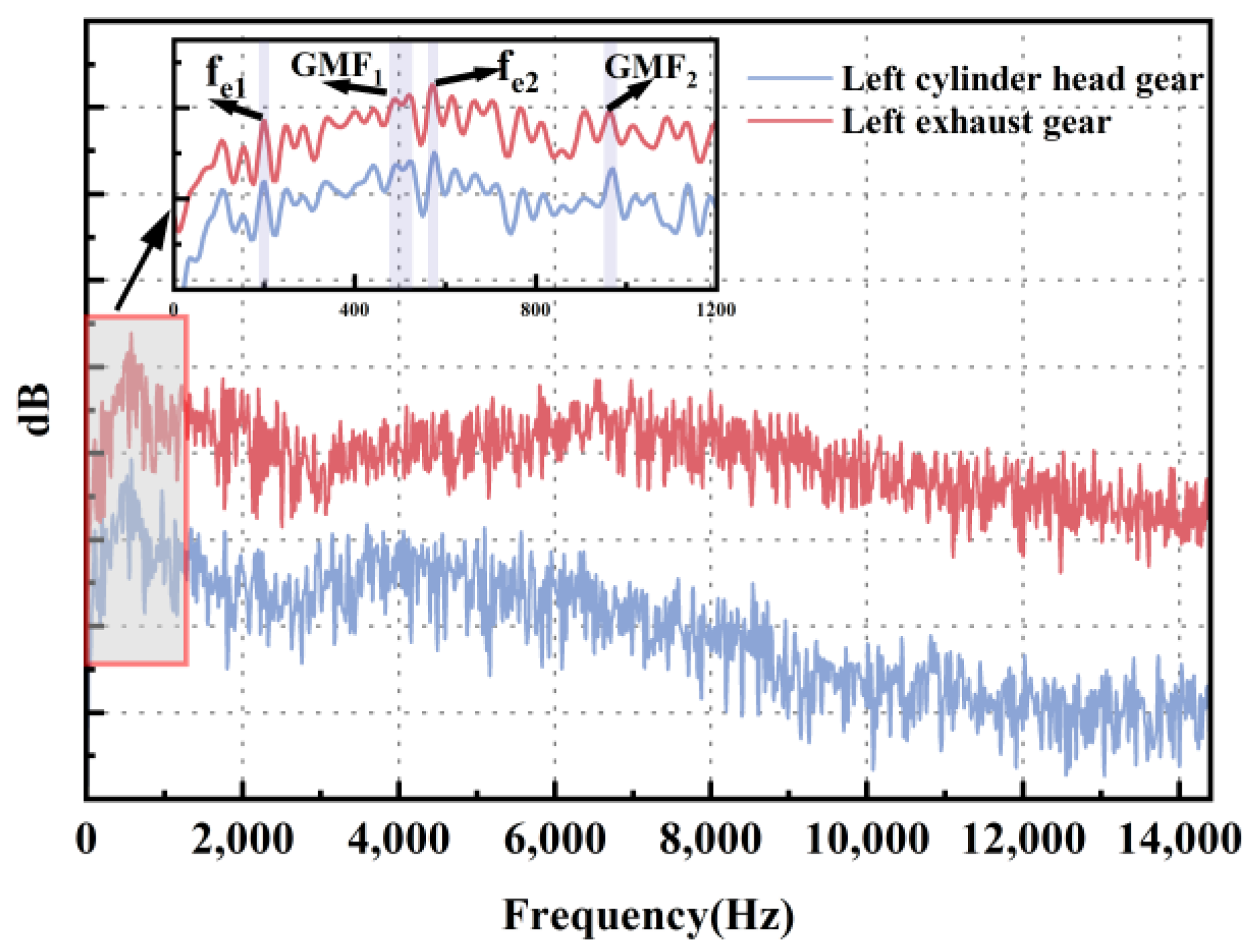
The spectrum of the gears exhibits prominent low-frequency peaks at 320 Hz and 750 Hz, which is attributed to the nonlinear characteristics of the bearing and gear contact. The spectrum of alternate-load-dominated gears exhibits a shifting phenomenon in low-frequency peaks, which is primarily attributable to variations in the internal contact state of the gears influenced by the alternate torques. The presence of these low-frequency peaks is both counterintuitive and potentially hazardous.
(2)
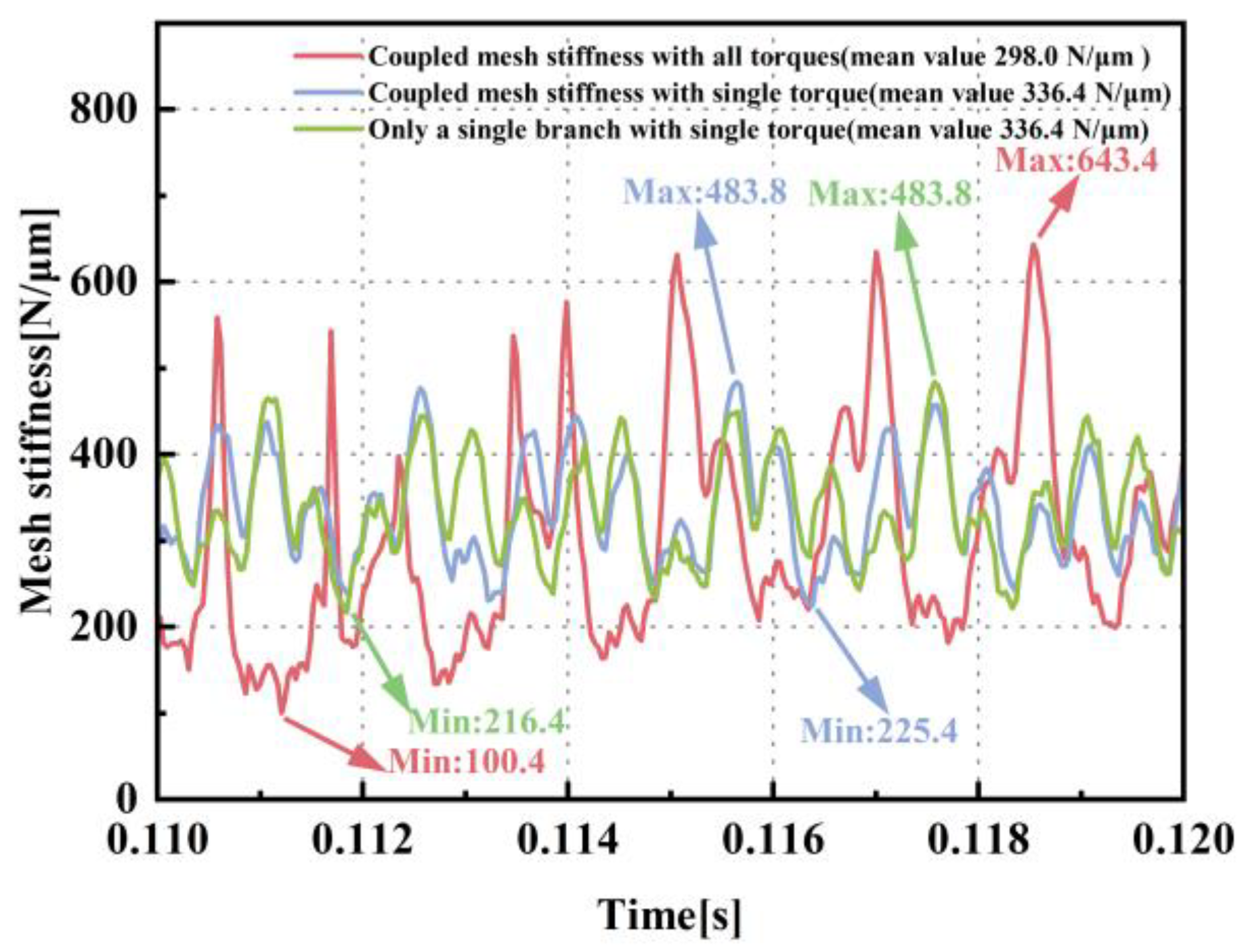
Under the coupled state, the maximum mesh stiffness demonstrates an increase of 69.5%, and the minimum mesh stiffness reaches only 31.5% of its non-coupled state value. The phenomena of marked oscillations in mesh stiffness come from the nonlinear dynamic coupling effects resulting from the propagation of external loads. The changes in the mesh stiffness characteristic can potentially lead to unforeseen failure issues under gear operating conditions.
(3)
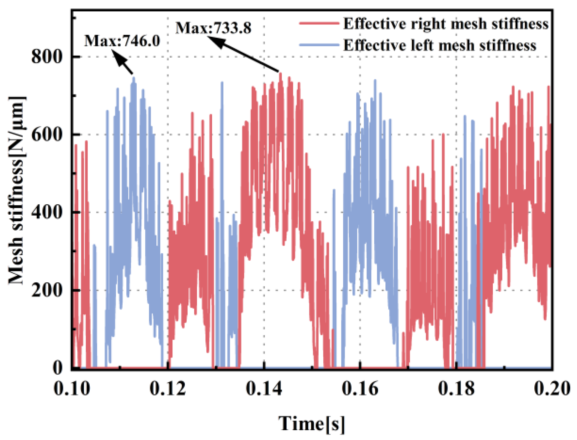
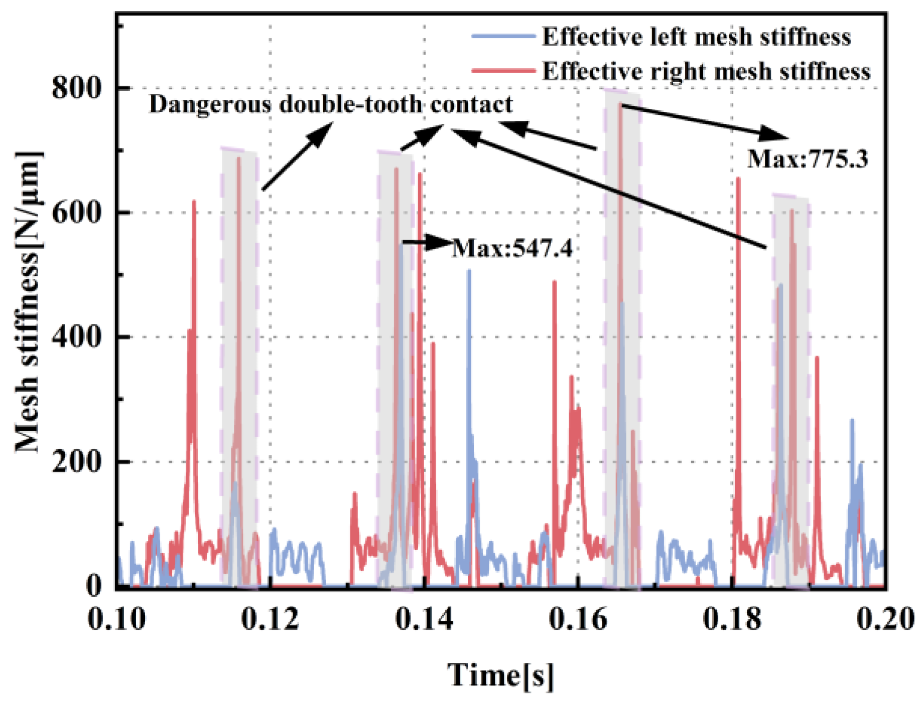
The intermediate gears are more susceptible to being influenced by counteracting asymmetric torques from adjacent gears, which implies that middle gears are relatively predisposed to developing double-tooth contact and potential failure. The presence of dangerous double-tooth contact regions at 0.115 s, 0.137 s, 0.165 s, and 0.188 s suggests that the failure of the gear transmission system is causally linked to the occurrence of periodic internal impact loads between the gears. The occurrence of internal impact loads is attributed to the delayed transmission effects of alternating loads in the intermediate gears.
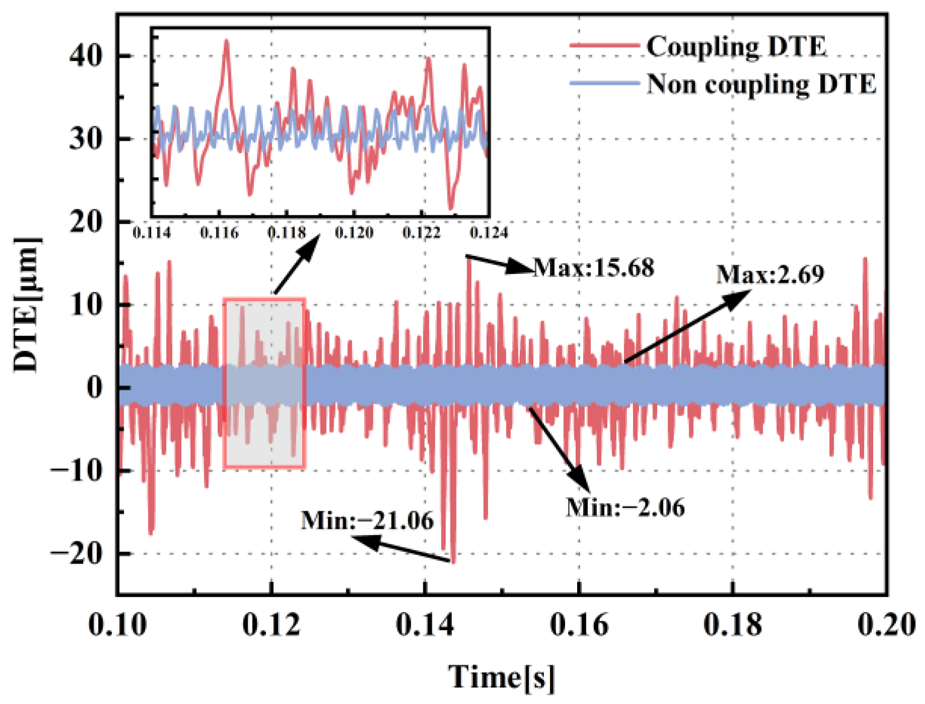
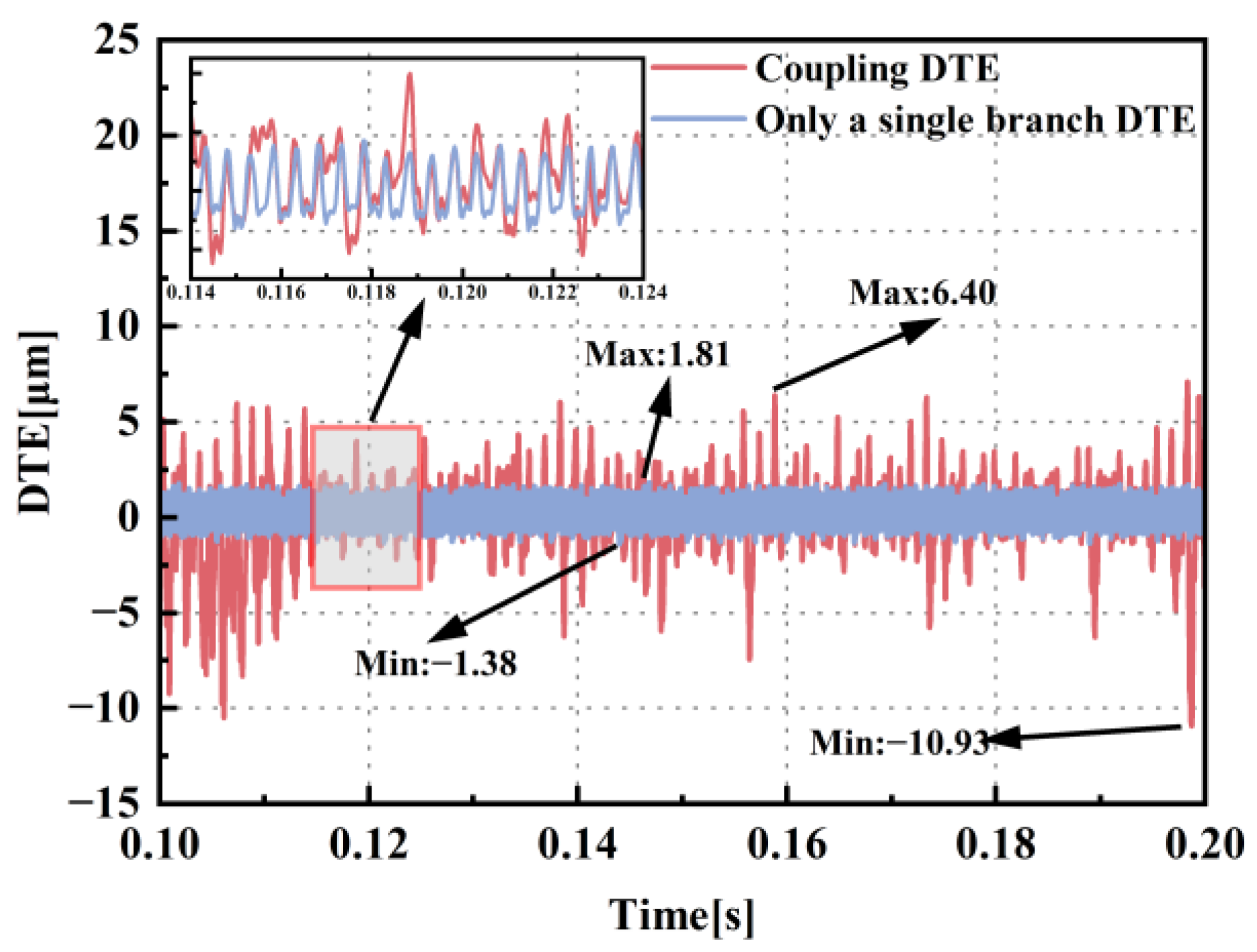
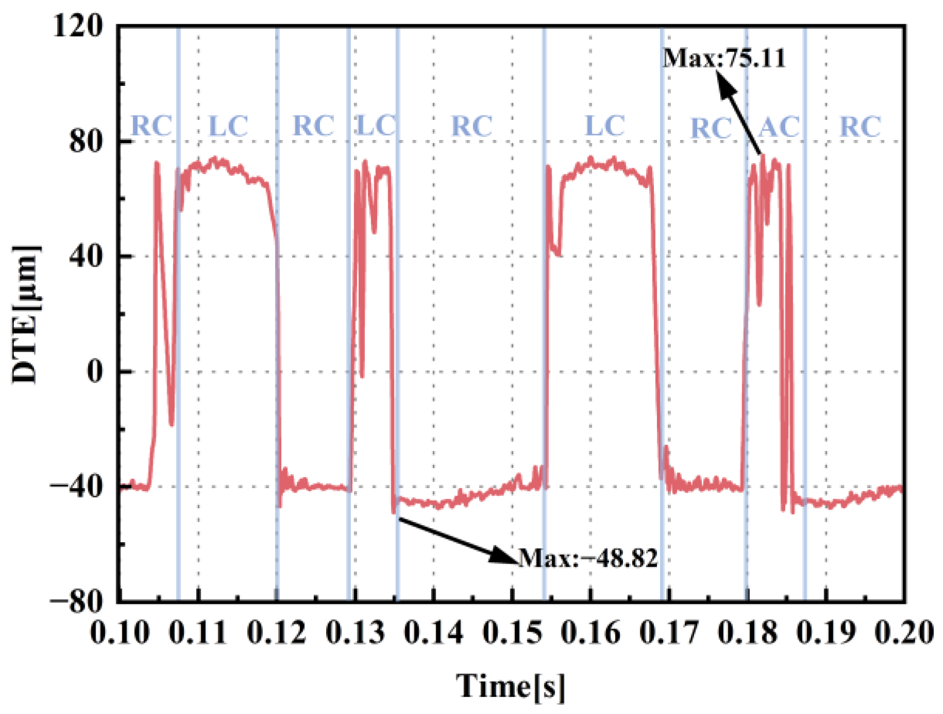
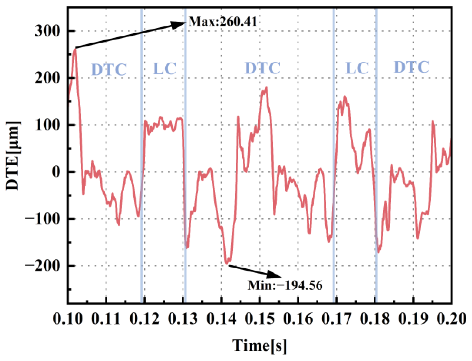
(4)
Under conditions of alternating torques, the variation in the DTE is strongly correlated with the dynamic behavior of the gear meshing state. When alternating torques cause changes in the gear meshing state, the STE within the gear pair evolves into DTE, leading to high-amplitude fluctuations and the nonlinear dynamic characteristics of DTE. The transmission of external loads through intermediate gear stages induces a propagation delay, which further yields multimodal DTE characteristics in the intermediate gears.
(5)
Alternating external loads are the dominant excitation source of vibrations, noise, and failures in the gear transmission system. The load-carrying gears generally exhibit high-amplitude vibration displacements and pronounced oscillatory characteristics compared to load-transmitting gears.

Author Contributions

Conceptualization, H.F. and P.R.; Methodology, H.F. and P.R.; Software, C.Y.; Validation, Z.Z. (Ziqing Zhu); Investigation, C.Y. and Z.Z. (Ziqing Zhu); Resources, H.F., Z.Z. (Zhongwei Zhang) and Q.Z.; Writing—original draft, C.Y.; Writing—review & editing, H.F. and P.R.; Visualization, Z.Z. (Ziqing Zhu); Supervision, P.R., Z.Z. (Zhongwei Zhang) and Q.Z.; Project administration, Z.Z. (Zhongwei Zhang) and Q.Z. All authors have read and agreed to the published version of the manuscript.

Funding

The authors gratefully acknowledge the support of the Vehicle Power Basic Research and Innovation Program (20242032906347), the China Postdoctoral Science Foundation (2023M740234), the National Funded Postdoctoral Researcher Program (GZC20233400), and the National Key Laboratory of Multi-perch Vehicle Driving Systems (QDXT-WY-202407-19).

Data Availability Statement

Data are contained within the article.

Conflicts of Interest

The authors declare no conflict of interest.

References

  1. Siyu, C.; Jinyuan, T.; Caiwang, L.; Qibo, W. Nonlinear dynamic characteristics of geared rotor bearing system with dynamic backlash and friction. Mech. Mach. Theory 2011, 46, 466–478. [Google Scholar] [CrossRef]
  2. Yi, Y.; Huang, K.; Xiong, Y.; Sang, M. Nonlinear dynamic modelling and analysis for a spur gear system with time-varying pressure angle and gear backlash. Mech. Syst. Signal Process. 2019, 132, 18–34. [Google Scholar] [CrossRef]
  3. Liu, P.; Zhu, L.; Gou, X.; Shi, J.; Jin, G. Dynamics modeling and analyzing of spur gear pair with pitch deviation considering time-varying contact ratio under multi-state meshing. J. Sound Vib. 2021, 513, 116411. [Google Scholar] [CrossRef]
  4. Zhou, D.; Guo, Y.; Yang, J.; Zhang, Y. Study on the Parameter Influences of Gear Tooth Profile Modification and Transmission Error Analysis. Machines 2024, 12, 316. [Google Scholar] [CrossRef]
  5. Wang, J.; Zhang, J.; Yao, Z.; Yang, X.; Sun, R.; Zhao, Y. Nonlinear characteristics of a multi-degree-of-freedom spur gear system with bending-torsional coupling vibration. Mech. Syst. Signal Process. 2019, 121, 810–827. [Google Scholar] [CrossRef]
  6. Bruzzone, F.; Rosso, C. Sources of excitation and models for cylindrical gear dynamics: A review. Machines 2020, 8, 37. [Google Scholar] [CrossRef]
  7. Li, Z.; Peng, Z. Nonlinear dynamic response of a multi-degree of freedom gear system dynamic model coupled with tooth surface characters: A case study on coal cutters. Nonlinear Dyn. 2016, 84, 271–286. [Google Scholar] [CrossRef]
  8. Mohammed, O.D.; Rantatalo, M.; Aidanpää, J.-O. Dynamic modelling of a one-stage spur gear system and vibration-based tooth crack detection analysis. Mech. Syst. Signal Process. 2015, 54, 293–305. [Google Scholar] [CrossRef]
  9. Xu, L.; Luo, Y.; Hu, R. A novel method of modelling contact dynamics for spur gear transmission. Mech. Mach. Theory 2024, 203, 105793. [Google Scholar] [CrossRef]
  10. Li, Y.; Chen, T.; Wang, X. Non-linear dynamics of gear pair with dynamic backlash subjected to combined internal and external periodic excitations. J. Vib. Control. 2016, 22, 1693–1703. [Google Scholar] [CrossRef]
  11. Li, H.; Chen, S.; Tang, J.; Sun, Z.; Hu, Y. Nonlinear dynamic modeling and analysis of spur gear based on gear compatibility conditions. Mech. Mach. Theory 2022, 171, 104767. [Google Scholar] [CrossRef]
  12. Tian, G.; Gao, Z.; Liu, P.; Bian, Y. Dynamic modeling and stability analysis for a spur gear system considering gear backlash and bearing clearance. Machines 2022, 10, 439. [Google Scholar] [CrossRef]
  13. Lin, T.; Ou, H.; Li, R. A finite element method for 3D static and dynamic contact/impact analysis of gear drives. Comput. Methods Appl. Mech. Eng. 2007, 196, 1716–1728. [Google Scholar] [CrossRef]
  14. Cirelli, M.; Valentini, P.P.; Pennestrì, E. A study of the non-linear dynamic response of spur gear using a multibody contact based model with flexible teeth. J. Sound Vib. 2019, 445, 148–167. [Google Scholar] [CrossRef]
  15. Guilbert, B.; Velex, P.; Dureisseix, D.; Cutuli, P. A mortar-based mesh interface for hybrid finite-element/lumped-parameter gear dynamic models—Applications to thin-rimmed geared system. J. Mech. Des. 2016, 138, 123301. [Google Scholar] [CrossRef]
  16. Liang, X.; Zhang, H.; Zuo, M.J.; Qin, Y. Three new models for evaluation of standard involute spur gear mesh stiffness. Mech. Syst. Signal Process. 2018, 101, 424–434. [Google Scholar] [CrossRef]
  17. Saxena, A.; Chouksey, M.; Parey, A. Measurement of FRFs of coupled geared rotor system and the development of an accurate finite element model. Mech. Mach. Theory 2018, 123, 66–75. [Google Scholar] [CrossRef]
  18. Liu, J.P.; Shu, X.B.; Kanazawa, H.; Imaoka, K.; Mikkola, A.; Ren, G.X. A model order reduction method for the simulation of gear contacts based on Arbitrary Lagrangian Eulerian formulation. Comput. Methods Appl. Mech. Eng. 2018, 338, 68–96. [Google Scholar] [CrossRef]
  19. Huangfu, Y.; Zeng, J.; Ma, H.; Dong, X.; Han, H.; Zhao, Z. A flexible-helical-geared rotor dynamic model based on hybrid beam-shell elements. J. Sound Vib. 2021, 511, 116361. [Google Scholar] [CrossRef]
  20. Liu, J.; Li, X.; Pang, R.; Xia, M. Dynamic modeling and vibration analysis of a flexible gear transmission system. Mech. Syst. Signal Process. 2023, 197, 110367. [Google Scholar] [CrossRef]
  21. Kong, X.; Hu, Z.; Tang, J.; Chen, S.; Wang, Z. Effects of gear flexibility on the dynamic characteristics of spur and helical gear system. Mech. Syst. Signal Process. 2023, 184, 109691. [Google Scholar] [CrossRef]
  22. Kong, X.; Tang, J.; Hu, Z.; Ding, H.; Wang, Z.; Wang, Q. Dynamic modeling and vibration analysis of spur gear system considering thin-walled gear and hollow shaft. Mech. Mach. Theory 2023, 181, 105197. [Google Scholar] [CrossRef]
  23. Schurr, D.; Holzwarth, P.; Eberhard, P. Investigation of dynamic stress recovery in elastic gear simulations using different reduction techniques. Comput. Mech. 2018, 62, 439–456. [Google Scholar] [CrossRef]
  24. Shweiki, S.; Rezayat, A.; Tamarozzi, T.; Mundo, D. Transmission Error and strain analysis of lightweight gears by using a hybrid FE-analytical gear contact model. Mech. Syst. Signal Process. 2019, 123, 573–590. [Google Scholar] [CrossRef]
  25. Kahraman, A. Dynamic analysis of a multi-mesh helical gear train. J. Mech. Des. 1994, 116, 706–712. [Google Scholar] [CrossRef]
  26. Li, W.; Li, Z.; Shi, H.; Li, X. Impact of phase configuration of a helical idler gear system on the vibration. Appl. Acoust. 2023, 211, 109467. [Google Scholar] [CrossRef]
  27. Yao, Z.; Lin, T.; Chen, Q.; Ren, H. Dynamic Response of Electromechanical Coupled Motor Gear System with Gear Tooth Crack. Machines 2024, 12, 918. [Google Scholar] [CrossRef]
  28. Li, Y.; Yuan, S.; Wu, W.; Song, X.; Liu, K.; Lian, C. Dynamic analysis of the helical gear transmission system in electric vehicles with a large helix angle. Machines 2023, 11, 696. [Google Scholar] [CrossRef]
  29. Yavuz, S.D.; Saribay, Z.B.; Cigeroglu, E. Nonlinear dynamic analysis of a drivetrain composed of spur, helical and spiral bevel gears. Nonlinear Dyn. 2020, 100, 3145–3170. [Google Scholar] [CrossRef]
  30. Liu, G.; Parker, R.G. Nonlinear dynamics of idler gear system. Nonlinear Dyn. 2008, 53, 345–367. [Google Scholar] [CrossRef]
  31. Vinayak, H.; Singh, R. Multi-body dynamics and modal analysis of compliant gear bodies. J. Sound Vib. 1998, 210, 171–214. [Google Scholar] [CrossRef]
  32. Jiang, S.; Li, W.; Wang, Y.; Yang, X.; Xu, S. Study on electromechanical coupling torsional resonance characteristics of gear system driven by PMSM: A case on shearer semi-direct drive cutting transmission system. Nonlinear Dyn. 2021, 104, 1205–1225. [Google Scholar] [CrossRef]
  33. Fakhfakh, H.; Bruyère, J.; Velex, P.; Becquerelle, S. A torsional model of multi-stage gears–influence of external excitations and tooth shape modifications. Mech. Ind. 2016, 17, 413. [Google Scholar] [CrossRef]
  34. Yavuz, S.D.; Saribay, Z.B.; Cigeroglu, E. Nonlinear time-varying dynamic analysis of a multi-mesh spur gear train. In Dynamics of Coupled Structures, Volume 4: Proceedings of the 34th IMAC, a Conference and Exposition on Structural Dynamics 2016; Springer: Cham, Switzerland, 2016; pp. 309–321. [Google Scholar]
  35. Gao, H.; Zhang, Y. Nonlinear behavior analysis of geared rotor bearing system featuring confluence transmission. Nonlinear Dyn. 2014, 76, 2025–2039. [Google Scholar] [CrossRef]
  36. Li, W.; Li, Z. Dynamic analysis of a multi-stage gear system considering the coupling between mesh phasing angle and coaxial teeth ratio. Nonlinear Dyn. 2023, 111, 19855–19878. [Google Scholar] [CrossRef]
  37. Neusser, Z.; Sopouch, M.; Schaffner, T.; Priebsch, H.-H. Multi-Body Dynamics Based Gear Mesh Models for Prediction of Gear Dynamics and Transmission Error; SAE Technical Paper; SAE International: Warrendale, PA, USA, 2010. [Google Scholar]
  38. Lu, W.; Zhang, Y.; Cheng, H.; Zhou, Y.; Lv, H. Research on dynamic behavior of multistage gears-bearings and box coupling system. Measurement 2020, 150, 107096. [Google Scholar] [CrossRef]
  39. Hu, Z.; Tang, J.; Wang, Q.; Chen, S.; Qian, L. Investigation of nonlinear dynamics and load sharing characteristics of a two-path split torque transmission system. Mech. Mach. Theory 2020, 152, 103955. [Google Scholar] [CrossRef]
  40. Yang, Y.; Li, H.; Dai, Y. Nonlinear vibration characteristics of spur gear system subjected to multiple harmonic excitations. Proc. Inst. Mech. Eng. Part C J. Mech. Eng. Sci. 2019, 233, 6026–6050. [Google Scholar] [CrossRef]
  41. ISO TR 10064-2-1996; Cylindrical Gears—Code of Inspection Practice—Part 2: Inspection Related to Radial Composite Deviations and Runout Verification. ISO: Geneva, Switzerland, 1996.
  42. Chen, Z.; Zhai, W.; Shao, Y.; Wang, K. Mesh stiffness evaluation of an internal spur gear pair with tooth profile shift. Sci. China Technol. Sci. 2016, 59, 1328–1339. [Google Scholar] [CrossRef]
Figure 1. The schematic of a nonlinear decoupled gear-bearing system model.
Machines 13 00416 g001
Figure 2. Three-dimensional multi-stage gear system model.
Machines 13 00416 g002
Figure 3. The alternating torques of the transmission system (N·m).
Machines 13 00416 g003
Figure 4. Coupled FE model of the multi-stage gear system model.
Machines 13 00416 g004
Figure 5. Grid independence verification.
Machines 13 00416 g005
Figure 6. Multi-stage rigid–flexible coupling multi-body dynamic simulation model in AVL.
Machines 13 00416 g006
Figure 7. Flow chart of the dynamic analysis.
Machines 13 00416 g007
Figure 8. Angular acceleration spectrum of a constant-load-dominated gear.
Machines 13 00416 g008
Figure 9. Angular acceleration spectrum of an alternate-load-dominated gear.
Machines 13 00416 g009
Figure 10. Meshing stiffness between the crankshaft gear and the upper idler gear.
Machines 13 00416 g010
Figure 11. Mesh stiffness between the oil pump idler gear and the oil pump gear under different conditions.
Machines 13 00416 g011
Figure 12. Meshing stiffness between the left exhaust gear and the left inlet gear.
Machines 13 00416 g012
Figure 13. Meshing stiffness between the left body idler and left valve idler gears.
Machines 13 00416 g013
Figure 14. DTE between the crankshaft gear and the upper idler gear.
Machines 13 00416 g014
Figure 15. DTE between the oil pump idler gear and the oil pump gear.
Machines 13 00416 g015
Figure 16. DTE between the left exhaust gear and the left inlet gear.
Machines 13 00416 g016
Figure 17. DTE between the left body idler and left valve idler gears.
Machines 13 00416 g017
Figure 18. Maximum vibration displacement of each gear.
Machines 13 00416 g018
Figure 19. Vibration displacement spectrum of a constant-load-dominated gear.
Machines 13 00416 g019
Figure 20. Vibration displacement spectrum of an alternating-load-dominated gear.
Machines 13 00416 g020
Table 1. Gear parameters for the transmission system.
Gear ModelGear AGear BGear CGear DGear EGear FGear GGear HGear IGear J
Teeth number50522653572754353125
Module/(mm)4443334444
Pressure angle/(°)20202020202020202020
Tooth width/(mm)4422233917.52018161618
Gear typehelicalhelicalhelicalSpurSpurSpurhelicalhelicalhelicalhelical
Circle helix angle/(°)12121200012121212
Disclaimer/Publisher’s Note: The statements, opinions and data contained in all publications are solely those of the individual author(s) and contributor(s) and not of MDPI and/or the editor(s). MDPI and/or the editor(s) disclaim responsibility for any injury to people or property resulting from any ideas, methods, instructions or products referred to in the content.

