
Hollow-Type Integrated Assembly Design and Performance Validation of Conductive Slip Rings via Simulation-Driven Optimization


Abstract
1. Introduction
2. Hollow Assembly of CSRs
2.1. Overall Design
- Drive Module: Combines the optical shaft drive with a sleeve-type coupling for power transmission;
- Clamping Module: Fixes the through-hole slip ring and optoelectronic encoder via the hollow connector frame, providing structural support;
- Protection Module: Includes the small-hole adapter plate and the guide sleeve-type protective cover. The former is fixed to the connector frame, and the latter provides protective integration with the slip ring and encoder;
- Instrumentation Module: Integrates the through-hole slip ring and optoelectronic encoder, with the encoder’s rotating shaft directly connected to the coupling of the drive module.
2.2. Design of the Drive Module
- Drive Layer: The small-hole adapter plate serves as the power input;
- Transmission Layer: Composed of the optical shaft drive, through-hole slip ring rotor, and sleeve-type coupling to form the motion transmission chain;
- Detection Layer: The optoelectronic encoder is directly connected via the coupling to receive rotational signal data.
2.2.1. Design of the Optical Shaft Drive
- Slip Ring Interface: The shaft and slip ring rotor are fitted using an H7/k6 transition fit. Radially distributed threaded holes with three radial set screws achieve circumferential locking, ensuring synchronization accuracy;
- Adapter Plate Interface: The shaft end features a standard keyway, with an A-type flat key forming a shear-resistant transmission fit with the small-hole adapter plate;
- Coupling Interface: The symmetric ends are equipped with identical keyway structures, establishing a torque transmission path with equal strength to the sleeve-type coupling.
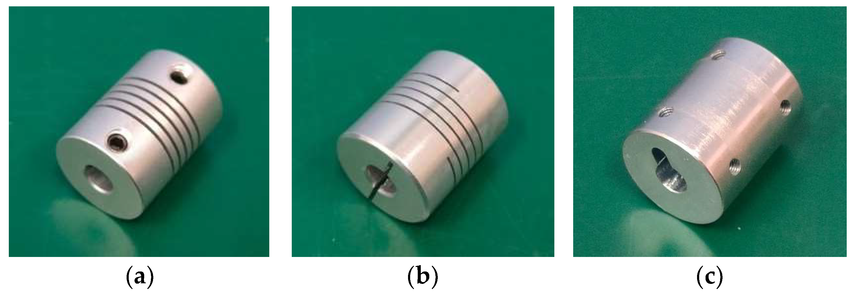
2.2.2. Design of the Sleeve Coupling
2.3. Design of the Clamping Module
2.4. Design of the Protection Module
2.4.1. Design of the Small Hole Type Adapter Plate
2.4.2. Design of the Guide Sleeve Type Fixed Cover
- Dynamic connection channel: The central hole on the left end ensures precise alignment between the through-hole slip ring rotor and the light-shaft transmission shaft, with precision bearings ensuring low-friction rotation;
- Wiring management system: Dual-row through-hole arrays are set along the side in the front–back direction for safely wiring the through-hole slip ring stator windings. Threaded hole sets on the vertical sides ensure precise positioning and assembly with the hollow connection frame;
- Integrated support frame: The right-end extension structure has four mounting holes for multi-directional support. The square opening integrates the optical encoder cable channel;
- Modular protection system: The entire component is made from 6061-T6 aluminum alloy, with O-ring grooves in critical areas.
2.5. Selection of Instrument Modules
2.5.1. Selection of Through-Hole Slip Rings
2.5.2. Selection of Optical Encoders
3. Finite Element Simulation Analysis
3.1. Establishment of the Assembly Simulation Model
3.1.1. Establishment of the 3D Model
3.1.2. Determination of Material Properties
3.1.3. Mesh Generation Processing
3.2. Static Simulation Analysis of the Hollow Assembly
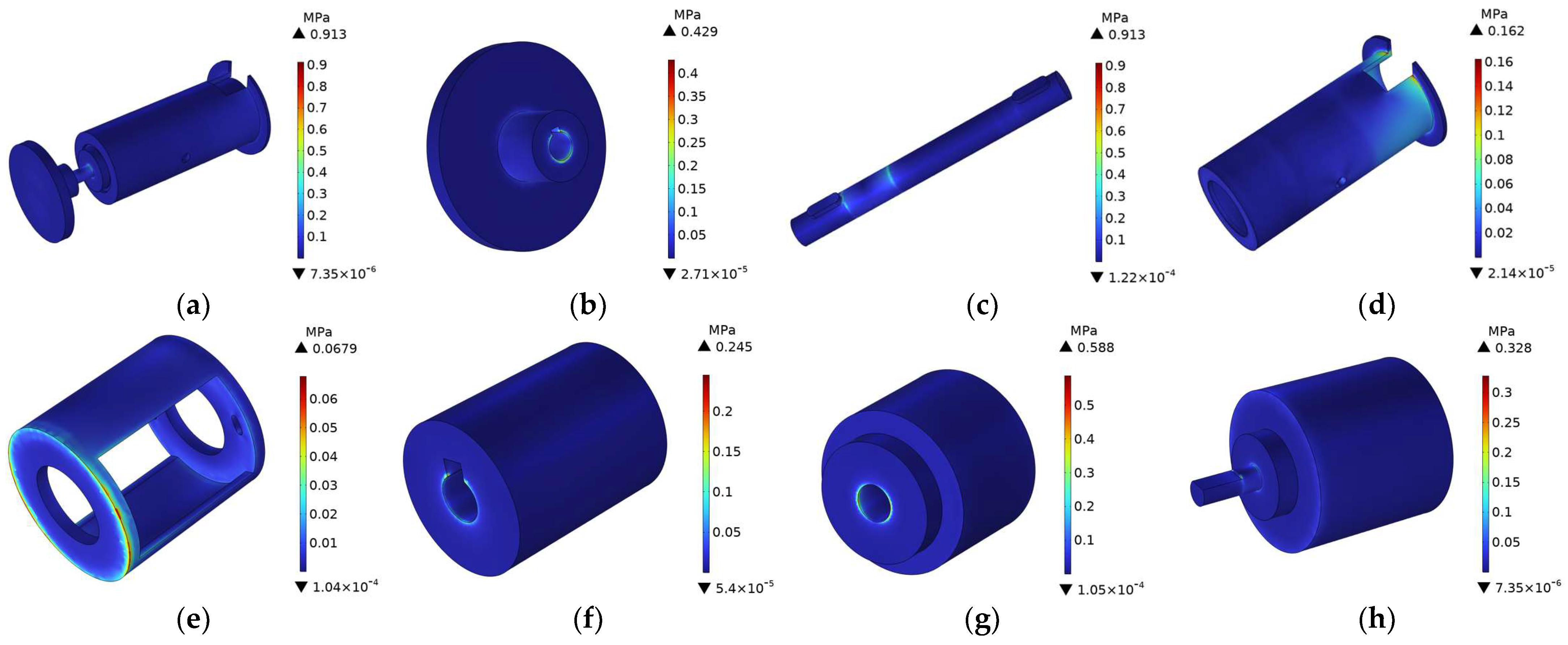
3.2.1. Effect of Assembly Angles of the Hollow Connector Frame on Assembly Accuracy
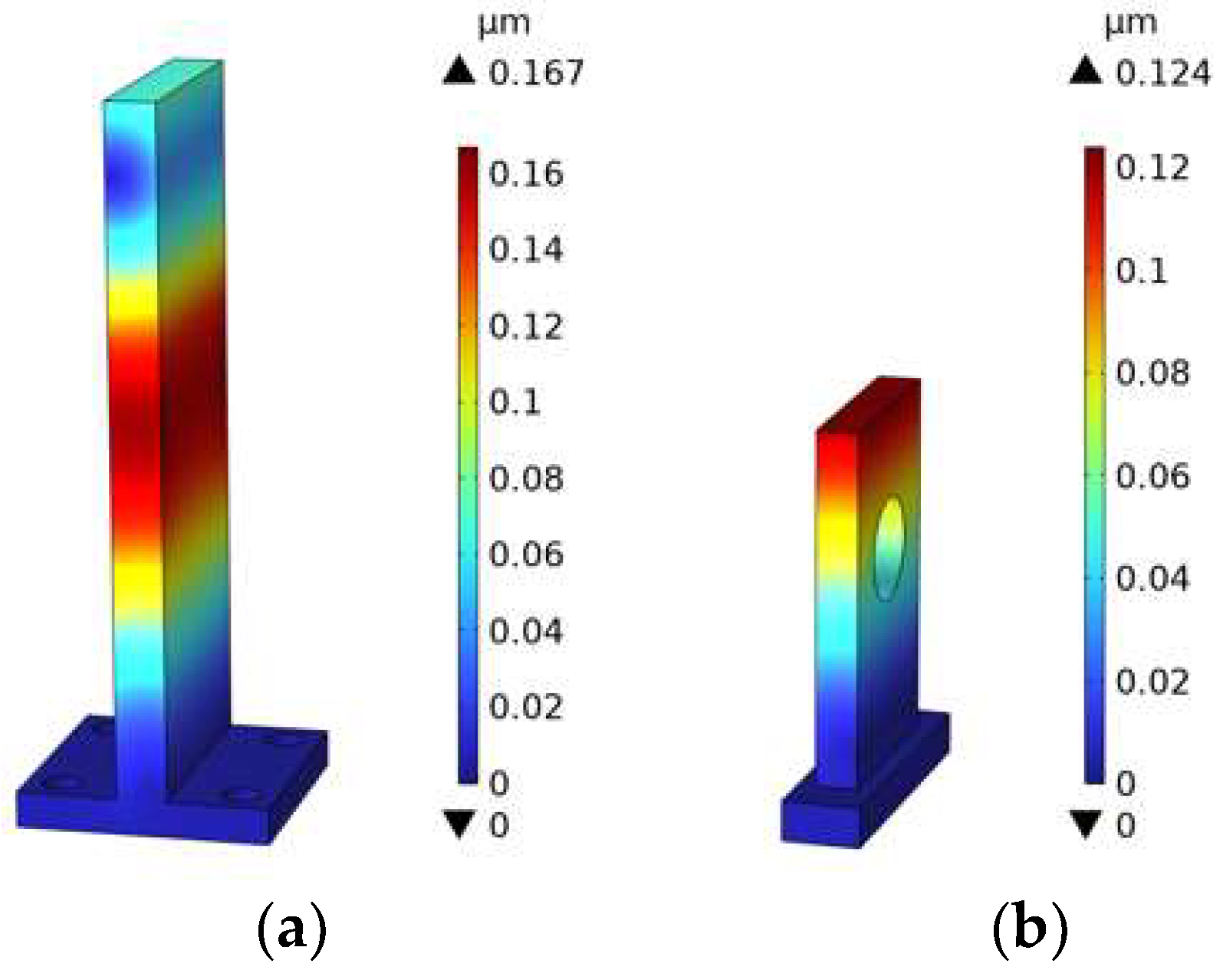
3.2.2. Influence of Gravity on the Structural Stability of the Assembly
3.3. Modal Analysis of the Dynamic Characteristics of the Hollow Assembly
4. Performance Testing of the Hollow-Type Integrated Assembly
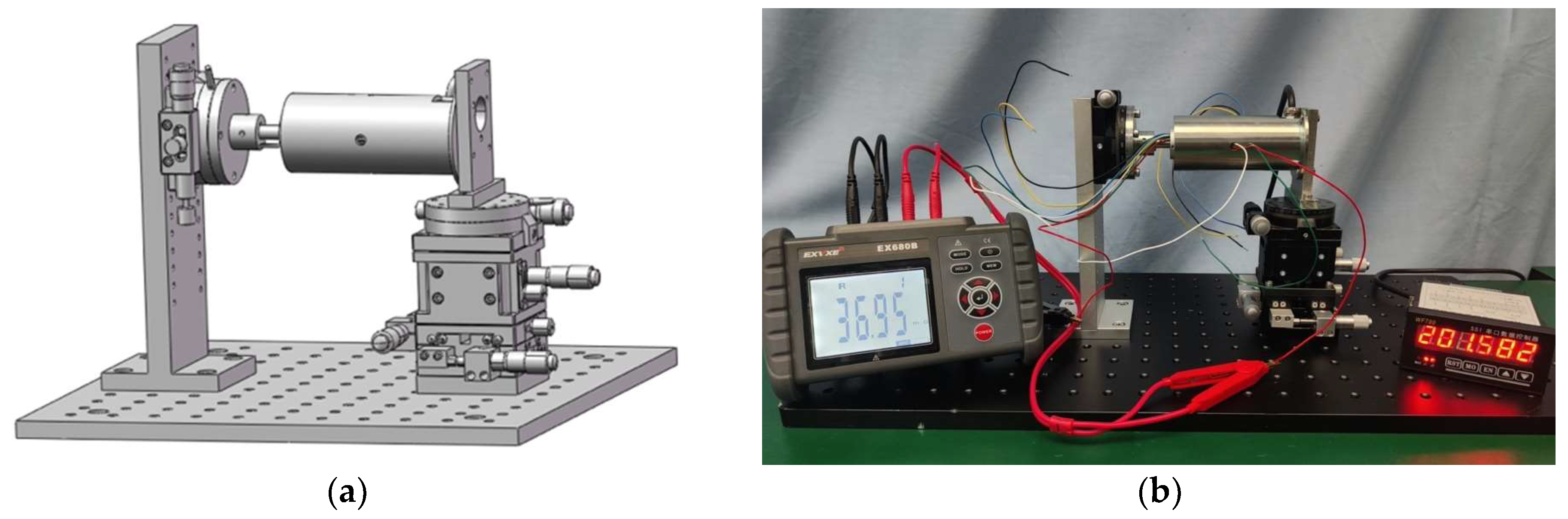
4.1. Assembly Platform Construction
- Precision: The test platform must ensure the precision necessary for evaluating the assembly’s operational accuracy. It is essential to select an appropriate reference datum and minimize assembly errors that might impact measurement accuracy;
- Stability: As the foundation for the system’s operational reliability and the accuracy of test data, the platform must incorporate a structurally stable rotational mechanism;
- Versatility: Given the structural diversity of potential assemblies, the platform should accommodate various assembly types, enabling flexible installation and clamping configurations.
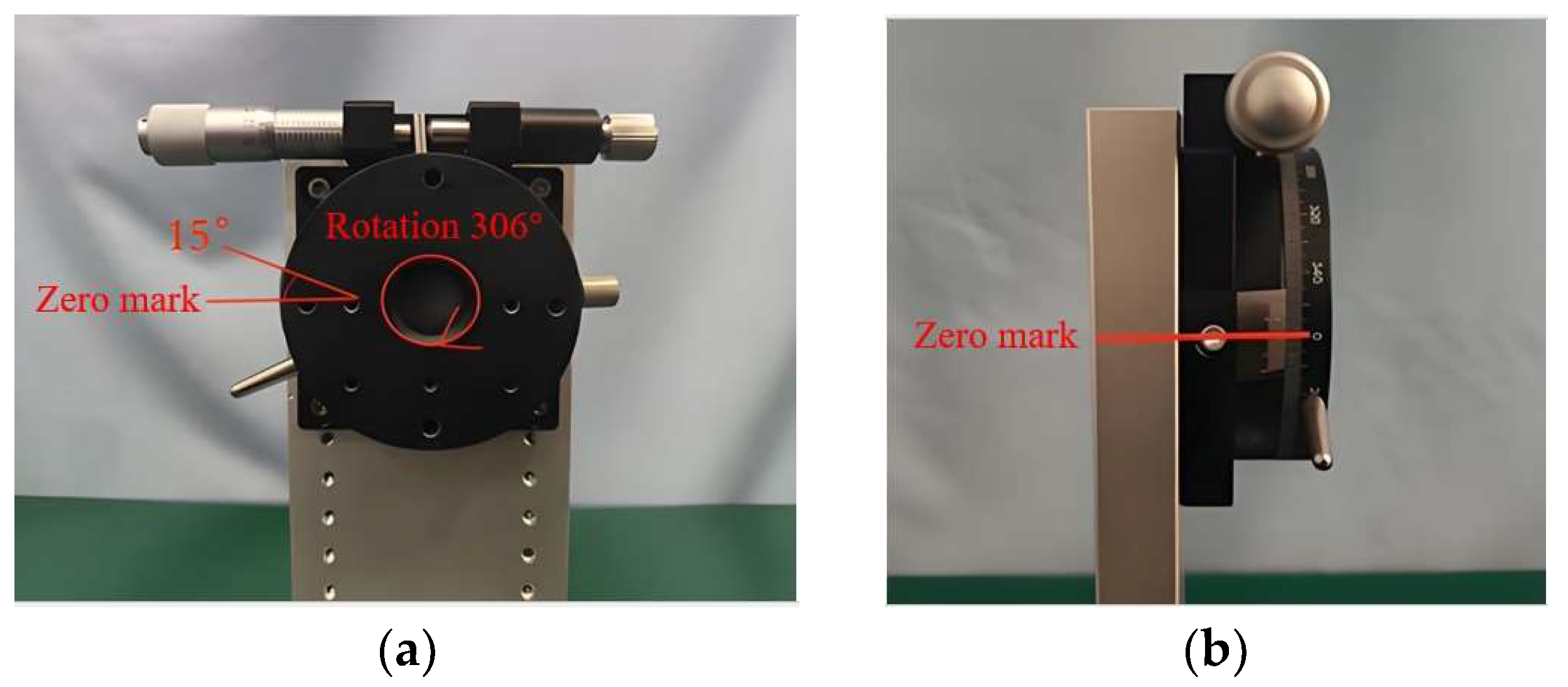
4.1.1. Calibration of the Rotating Platform
4.1.2. Design of the Support Module
4.1.3. Selection of the Displacement Module
4.1.4. Selection of the Digital Display Module
4.2. Assembly Sequence of the Hollow-Type Integrated Structure
- Mount the optical-shaft-type drive shaft inside the rotor of the through-hole slip ring, ensuring that the side with the keyway is near the slip ring stator lead;
- Attach the sleeve-type coupling to the drive shaft on the side close to the keyway;
- Install the side of the hollow connector frame with a straight slot at the stator lead area of the through-hole slip ring and guide the wires through the slot;
- Mount the photoelectric encoder onto the hollow connector frame, inserting its rotating shaft into the sleeve coupling;
- Insert the guide sleeve-type protective cover from the lead end of the slip ring rotor and route the wires through the wiring hole;
- Mount the small-hole-type adapter plate onto the drive shaft to complete the assembly.
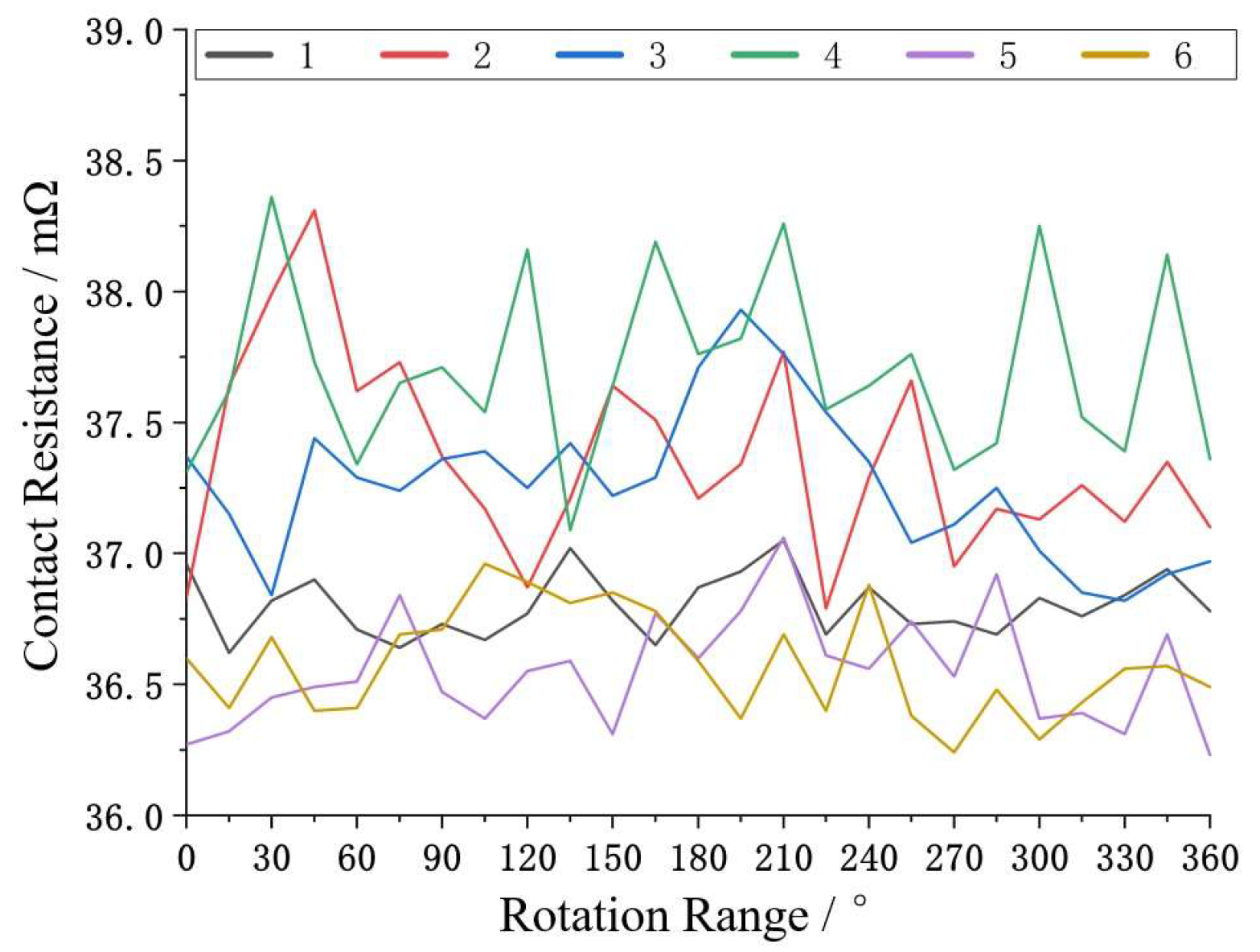
4.3. Contact Resistance Test of the Hollow-Type Integrated Structure
4.4. Rotational Angle Testing of the Hollow-Type Integrated Assembly
4.4.1. Comparative Test of Different Transfer Modes of Hollow Assembly
4.4.2. Comparative Study of Fixation Methods on the Transmission Accuracy of the Hollow-Type Assembly
4.4.3. Repeatability Testing of the Hollow-Type Assembly’s Angular Displacement
4.4.4. Angular Accuracy Testing of the Hollow-Type Assembly
5. Conclusions
- A complete scheme for the hollow-type assembly was designed. The transmission module includes a design for a smooth shaft drive and a sleeve-type coupling. The clamping module incorporates both hollow and flange-type connecting frames. The protective module comprises a small-aperture adapter plate and a guide-sleeve cover. The instrumentation module includes the selection of a through-hole slip ring and a photoelectric encoder, with the final slip ring chosen as the Senring H0835-0605TC model. The reliability of the assembly was ensured through torsional theory analysis and simulation.
- Static analysis determined the optimal assembly angle to be 0°, yielding a maximum stress of 0.913 MPa and a maximum displacement of 0.0316 μm—both well below the allowable design thresholds, indicating ample safety margin. Modal analysis revealed that the hollow-type frame’s natural frequency ranges from 585.24 Hz to 4431.20 Hz, with the first mode at 585.24 Hz, significantly exceeding the 400 Hz requirement. Comparatively, the flange-type frame exhibited approximately 30% lower dynamic stability.
- A dedicated performance testing system was developed based on the R-axis rotary platform, offering an angular resolution of 0.001°, a rotational speed range of 0–100 rpm, and a data acquisition frequency of 10 kHz—providing a robust foundation for performance evaluation. In terms of electrical performance, contact resistance remained between 36.23 and 38.76 mΩ, with fluctuation under 10 mΩ, fully meeting design specifications. In terms of mechanical performance, the custom sleeve-type coupling reduced angular displacement error by approximately 40%, while the hollow-type frame effectively decreased vibration response by 35%. The angular repeatability reached 499.8″ and the accuracy 705.6″—both superior to the technical requirements.
Author Contributions
Funding
Data Availability Statement
Acknowledgments
Conflicts of Interest
Abbreviations
| CSR | Conductive slip ring |
References
- Dong, T.Y.; Li, L.; Wei, H.X. Introduction to the formulation of CB 20363-2018 Code for Conductive slip Rings for Shipborne Radar. Shipbuild. Stand. Qual. 2019, 2019, 25–27+20. [Google Scholar]
- Zhang, Q.; Zhang, K.M.; Liu, J.K. Overview of Research and Development on Space Slip Rings. J. Mech. Eng. 2022, 58, 334–348. [Google Scholar]
- Liu, B.; Lu, X. Interpolation error analysis of photoelectric encoder based on improved genetic algorithm. J. Electron. Meas. Instrum. 2019, 33, 15–20. [Google Scholar]
- Niu, G.; Wu, H.; Qian, Z.; Liu, C.; Ma, Z. Research on the prediction model for the wear of bundle brush conductive slip ring in spacecraft. In Proceedings of the SPIE 12801, Ninth International Conference on Mechanical Engineering, Materials, and Automation Technology (MMEAT 2023), 12801, Dalian, China, 9–11 June 2023; pp. 549–564. [Google Scholar]
- Zhang, S.M.; Qiang, Q.; Liu, L.Y.; Jie, X. Effect of Ring Hardness on Friction and Wear Properties of Gold-base Alloy Slip Rings. Tribology 2024, 44, 358–367. [Google Scholar]
- Li, J.Y.; Li, J.; Wang, X.P.; Tian, G.; Fan, J. Machine vision-based method for measuring and controlling the angle of conductive slip ring brushes. Micromachines 2022, 13, 447. [Google Scholar] [CrossRef] [PubMed]
- Chen, X.; Wang, Y.; Sheng, Y.; Yu, C.; Yang, X.; Xi, J. Vision-Aided Brush Alignment Assembly System for Precision Conductive Slip Rings. Machines 2022, 10, 393. [Google Scholar] [CrossRef]
- Jia, Q.J.; Yao, P. Frictional Torque Analysis of Space Conductive Slip Ring under Vacuum and High and Low Temperature Environment. Lubr. Eng. 2020, 45, 123–127. [Google Scholar]
- Yang, J.Y.; Liu, M.H.; Song, X.L.; Lei, J.J. Numerical study on heat transfer characteristics of brush seal. J. Mech. Electr. Eng. 2021, 38, 1230–1237. [Google Scholar]
- Jiang, K.; Li, J.W.; Gao, F. Structure Design of Conductive Slip Ring for Underwater Micro-submersible Submarine. Mach. Build. Autom. 2020, 49, 28–30. [Google Scholar]
- Li, W.G.; Fu, H.B.; Zhang, F.F. Research on a new type of ultra-small conductive slip ring. Technol. Innov. Appl. 2022, 12, 57–59+64. [Google Scholar]
- Li, W.G.; Fu, H.B.; Zhang, F.F. The utility model relates to a long life conductive slip ring which is convenient for center of mass trimming. Technol. Innov. Appl. 2020, 2022, 92–93. [Google Scholar]
- Liu, M.; Meng, L.X.; Zhang, L.Z.; Chen, L.B.; Zhang, Z.W. Study on fatigue characteristics of ‘goose-neck’ type limited angle Conductive Slip Ring. J. Chang. Univ. Sci. Technol. (Nat. Sci. Ed.) 2021, 44, 44–50. [Google Scholar]
- Feng, T.; Chen, W.L.; Qiu, J.J.; Hao, S.H. A new kind of absolute magnetic encoder. Sensors 2021, 21, 3095. [Google Scholar] [CrossRef]
- Wang, S.D.; Zhu, W.L.; Shen, Y.J.; Ren, J.; Gu, H.R.; Wei, X.Y. Temperature compensation for MEMS resonant accelerometer based on genetic algorithm optimized backpropagation neural network. Sens. Actuators A Phys. 2020, 316, 112393. [Google Scholar] [CrossRef]
- Han, S.; Ahn, Y.; Kang, K.; Shin, J.W. Short-segment speaker verification using ECAPA-TDNN with multi-resolution encoder. In Proceedings of the CASSP 2023–2023 IEEE International Conference on Acoustics, Speech and Signal Processing (ICASSP), Rhodes Island, Greece, 4–10 June 2023; pp. 1–5. [Google Scholar]
- Sun, Z.; Sumsion, A.W.; Torrie, S.A.; Lee, D.J. Learning facial motion representation with a lightweight encoder for identity verification. Electronics 2022, 11, 1946. [Google Scholar] [CrossRef]
- Zhang, B.; Li, Y.; Chen, X.L. Design and development of high precision magnetic encoder for servo positioning experiment system. Exp. Technol. Manag. 2021, 38, 183–192. [Google Scholar]
- Wang, C.F.; Xue, C.R.; Huang, H.Y. Improved design of installation structure of rotary encoder for shotcreting robot. Coal Mine Mach. 2023, 44, 129–131. [Google Scholar]
- Huang, L.X.; Huang, J.Y.; Huang, L.J. Design of encoder based on giant magnetoresistance sensor. Appl. IC 2023, 40, 11–13. [Google Scholar]
- Yin, Q.Y.; Wu, R.P.; Chen, W.W. Survival analysis algorithm based on multi-omics data and variational sparse autoencoder. Appl. Res. Comput. 2023, 40, 771–775. [Google Scholar]
- Sheng, D.D. Design and Error Compensation of Magnetic Encoder; Northeast Electric Power University: Jilin, China, 2023. [Google Scholar]
- Zhao, R.F. Design and Realization of High-Resolution and High-Accuracy Magnetic Encoder Based on TMR; Hangzhou Dianzi University: Hangzhou, China, 2021. [Google Scholar]
- Ludois, D.C.; Frankforter, K. A rotating double layer capacitive slip ring concept for power & heat transfer in machines using an ionic conducting working fluid. In Proceedings of the 2020 IEEE Energy Conversion Congress and Exposition (ECCE), Detroit, MI, USA, 11–15 October 2020; pp. 4238–4245. [Google Scholar]
- Tu, W.Y.; Qian, J.; Xu, X.D. Assembly analysis of the axial system of large high-precision optical shaft encoder. Manuf. Technol. Mach. Tool 2011, 2011, 46–48. [Google Scholar]
- Wang, X.Y. Connection between motors and encoders as well as its assembly points. Electr. Mach. Technol. 2020, 2020, 57–59. [Google Scholar]
- Li, G.J. Mechanical and finite element analysis of membrane coupling. Heavy Mach. 2022, 2022, 76–80. [Google Scholar]
- Xue, R.B. Between shaft and shaft coupling research in production and improve the design. Friend Sci. Amat. 2013, 2013, 35–37. [Google Scholar]
- Ma, J.; Meng, G. Structural design of interference fit coupling. Intern. Combust. Engine Parts 2019, 2019, 122–123. [Google Scholar]
- Zhao, Z.D.; Cun, W.Y.; Qian, J.; Zhao, X.S.; Shu, Y.; Chen, G. Simulation analysis and test verification of aircraft pipeline fatigue performance. Noise Vib. Control 2023, 43, 239–244+279. [Google Scholar]
- Zhang, T.Y. Assembly Accuracy Prediction and Control for Precision Mechanical System; Beijing Institute of Technology: Beijing, China, 2016. [Google Scholar]
- Zhang, B.Y. Development of an Angle Encoder Calibration Device for High and Low Temperature Environments; China Jiliang University: Hangzhou, China, 2019. [Google Scholar]
- ISO 9283-1998; Manipulating Industrial Robots: Performance Criteria and Related Test Methods. International Organization for Standardization: Geneva, Switzerland, 1998.


| Materials | Density | Young’s Modulus | Poisson’s Ratio | Yield Limit | Strength Limit |
|---|---|---|---|---|---|
| 45 steel | /kg/m3 | E/GPa | /MPa | /MPa | |
| 7810 | 200.1 | 0.269 | 355 | 696.6 |
| Angle /° | X-Direction /μm | Y-Direction /μm | Z-Direction /μm | Total Displacement /μm | Von Mises Stress /MPa |
|---|---|---|---|---|---|
| 0 | 0.0003 | 0.0034 | 0.0273 | 0.0276 | 0.0679 |
| 45 | 0.0004 | 0.0034 | 0.0270 | 0.0273 | 0.1030 |
| 90 | 0.0004 | 0.0033 | 0.0268 | 0.0271 | 0.1090 |
| Order | 1 | 2 | 3 | 4 | 5 | 6 |
|---|---|---|---|---|---|---|
| Natural frequency (Hollow-type) | 585.24 | 590.45 | 846.49 | 1903.30 | 2006.20 | 4431.20 |
| Danger area (Hollow-type) | Small-hole-type transfer plate on both sides | Small-hole-type transfer plate left and right sides | Eyelet adapter plate outer edge area | Small-hole-type adapter plate up and down and through-hole-type slip ring area | Small-hole-type adapter plate left and right and through-hole-type slip ring area | The left and right side of the pinhole transfer plate and the photoelectric encoder area |
| Natural frequency (Flange-type) | 409.98 | 411.69 | 625.92 | 979.18 | 981.84 | 1682.40 |
| Danger area (Flange-type) | Access area of the small-hole adapter board | Access area of the small-hole adapter board | Eyelet adapter plate outer edge area | Small-hole-type adapter plate and through-hole-type slip ring flange area | Small-hole-type adapter plate left and right and through-hole-type slip ring flange area | Pass-type slip ring flange and fixed-rod part area |
| XYZ-Axis Displacement Platform Model | LD60-LM-2 |
|---|---|
| XY-stroke | 6.5 mm |
| Z-stroke | 10 mm |
| Minimum scale | 0.01 mm |
| Precision | 0.03 mm |
| Parallelism | 0.03 mm |
| R-Axis Rotary Platform Model | RSP60-L |
|---|---|
| Mesa size | 60 |
| Journey | fine adjustment |
| Angular accuracy | 72″ |
| Minimum scale | 5 mm |
| Concentricity | 0.02 mm |
| Parallelism | 0.02 mm |
| DC Low-Resistance Meter Model | EX680B |
|---|---|
| Resistance range | |
| Resolution | |
| Precision | |
| Detection method | Four-wire test |
| Test current | ≥1A |
| Rotational Angular Displacement /″ | Test Angular Displacement /″ | Absolute Error /″ |
|---|---|---|
| 54,000 | 53,485.2 | −514.8 |
| 108,000 | 107,920.8 | −79.2 |
| 162,000 | 162,669.6 | +669.6 |
| 216,000 | 215,841.6 | −158.4 |
| 270,000 | 269,326.8 | −673.2 |
| 324,000 | 324,075.6 | +75.6 |
| 378,000 | 378,511.2 | +511.2 |
| 432,000 | 432,630.0 | +630.0 |
| 486,000 | 485,485.2 | −514.8 |
| 540,000 | 539,604.0 | −396.0 |
| 594,000 | 594,669.6 | +669.6 |
| 648,000 | 647,841.6 | −158.4 |
| 702,000 | 702,273.6 | +273.6 |
| 756,000 | 756,392.4 | +392.4 |
| 810,000 | 809,564.4 | −435.6 |
| 864,000 | 863,683.2 | −316.8 |
| 918,000 | 918,115.2 | +115.2 |
| 972,000 | 972,234.0 | +234.0 |
| 1,026,000 | 1,026,352.8 | +352.8 |
| 1,080,000 | 1,079,524.8 | −475.2 |
| 1,134,000 | 1,133,960.4 | −39.6 |
| 1,188,000 | 1,188,075.6 | +75.6 |
| 1,242,000 | 1,242,511.2 | +511.2 |
| 1,296,000 | 1,296,630.0 | +630.0 |
| Rotational Angular Displacement /″ | Test Angular Displacement /″ | Absolute Error /″ |
|---|---|---|
| 54,000 | 53,485.2 | −594.0 |
| 108,000 | 107,287.2 | −712.8 |
| 162,000 | 161,722.8 | −277.2 |
| 216,000 | 216,154.8 | +154.8 |
| 270,000 | 270,590.4 | +590.4 |
| 324,000 | 324,709.2 | +709.2 |
| 378,000 | 377,247.6 | −752.4 |
| 432,000 | 431683.2 | −316.8 |
| 486,000 | 486,432.0 | +432.0 |
| 540,000 | 540,234.0 | +234.0 |
| 594,000 | 593,722.8 | −277.2 |
| 648,000 | 647,841.6 | −158.4 |
| 702,000 | 701,960.4 | −39.6 |
| 756,000 | 756,392.4 | +392.4 |
| 810,000 | 809,247.6 | +752.4 |
| 864,000 | 863,366.4 | +633.6 |
| 918,000 | 917,802.0 | −198.0 |
| 972,000 | 972,234.0 | +234.0 |
| 1,026,000 | 1,026,352.8 | +352.8 |
| 1,080,000 | 1,080,788.4 | +788.4 |
| 1,134,000 | 1,133,326.8 | −673.2 |
| 1,188,000 | 1,188,392.4 | +392.4 |
| 1,242,000 | 1,241,564.4 | −435.6 |
| 1,296,000 | 1,295,683.2 | −316.8 |
| Rotational Angular Displacement /″ | Test Angular Displacement /″ | Absolute Error /″ |
|---|---|---|
| 54,000 | 53,802.0 | −198.0 |
| 108,000 | 107,604.0 | −396.0 |
| 162,000 | 161,722.8 | −277.2 |
| 216,000 | 215,841.6 | −158.4 |
| 270,000 | 269,960.4 | −39.6 |
| 324,000 | 324,075.6 | +75.6 |
| 378,000 | 378,511.2 | +511.2 |
| 432,000 | 431,366.4 | −633.6 |
| 486,000 | 485,485.2 | −514.8 |
| 540,000 | 540,550.8 | +550.8 |
| 594,000 | 593,722.8 | −277.2 |
| 648,000 | 648154.8 | +154.8 |
| 702,000 | 702,273.6 | +273.6 |
| 756,000 | 756,392.4 | +392.4 |
| 810,000 | 809,881.2 | −118.8 |
| 864,000 | 864,630.0 | +630.0 |
| 918,000 | 918,115.2 | +115.2 |
| 972,000 | 971,920.8 | −79.2 |
| 1,026,000 | 1,025,722.8 | −277.2 |
| 1,080,000 | 1,079,841.6 | −158.4 |
| 1,134,000 | 1,134,273.6 | +273.6 |
| 1,188,000 | 1,188,392.4 | +392.4 |
| 1,242,000 | 1,241,564.4 | −435.6 |
| 1,296,000 | 1,296,313.2 | +313.2 |
| Rotational Angular Displacement /″ | Test Angular Displacement /″ | Absolute Error /″ |
|---|---|---|
| 54,000 | 53,802.0 | −198.0 |
| 108,000 | 107,604.0 | −396.0 |
| 162,000 | 162,352.8 | +352.8 |
| 216,000 | 216,154.8 | +154.8 |
| 270,000 | 269,643.6 | −356.4 |
| 324,000 | 324,075.6 | +75.6 |
| 378,000 | 377,881.2 | −118.8 |
| 432,000 | 431,366.4 | −633.6 |
| 486,000 | 485,802.0 | −198.0 |
| 540,000 | 539,920.8 | −79.2 |
| 594,000 | 594,352.8 | +352.8 |
| 648,000 | 647,841.6 | −158.4 |
| 702,000 | 701,960.4 | −39.6 |
| 756,000 | 755,762.4 | −237.6 |
| 810,000 | 810,511.2 | +511.2 |
| 864,000 | 863,683.2 | −316.8 |
| 918,000 | 918,432.0 | +432.0 |
| 972,000 | 971,920.8 | −79.2 |
| 1,026,000 | 1,025,406.0 | −594.0 |
| 1,080,000 | 1,080,154.8 | +154.8 |
| 1,134,000 | 1,134,273.6 | +273.6 |
| 1,188,000 | 1,188,075.6 | +75.6 |
| 1,242,000 | 1,241,881.2 | −118.8 |
| 1,296,000 | 1,295,683.2 | −316.8 |
| Rotational Angular Displacement /″ | Test Angular Displacement /″ | Absolute Error /″ |
|---|---|---|
| 54,000 | 54,115.2 | +115.2 |
| 108,000 | 107,920.8 | −79.2 |
| 162,000 | 162,026.0 | +36.0 |
| 216,000 | 216,471.6 | +471.6 |
| 270,000 | 270,273.6 | +273.6 |
| 324,000 | 324,392.4 | +392.4 |
| 378,000 | 377,881.2 | −118.8 |
| 432,000 | 432,000.0 | 0.0 |
| 486,000 | 486,432.0 | +432.0 |
| 540,000 | 539,920.8 | −79.2 |
| 594,000 | 594,036.0 | +36.0 |
| 648,000 | 647,841.6 | −158.4 |
| 702,000 | 702,590.4 | +590.4 |
| 756,000 | 755,445.6 | −554.4 |
| 810,000 | 809,564.4 | −435.6 |
| 864,000 | 863,366.4 | −633.6 |
| 918,000 | 917,802.0 | −198.0 |
| 972,000 | 971,920.8 | −79.2 |
| 1026,000 | 1,026,352.8 | +352.8 |
| 108,0000 | 1,079,841.6 | −158.4 |
| 1,134,000 | 1,134,590.4 | +590.4 |
| 1,188,000 | 1,188,075.6 | +75.6 |
| 1,242,000 | 1,242,194.4 | +194.4 |
| 1,296,000 | 1,296,630.0 | +630.0 |
| Rotational Angular Displacement /″ | 1 | 2 | 3 | 4 | 5 | Mean Value |
|---|---|---|---|---|---|---|
| 0 | 0 | 0 | 0 | 0 | 0 | 0 |
| 54,000 | 53,485.2 | 54,115.2 | 53,168.4 | 54,432.0 | 53,802.0 | 53,800.6 |
| 1,080,00 | 108,867.6 | 108,234.0 | 107,604.0 | 108,550.8 | 107,920.8 | 108,235.4 |
| 162,000 | 161,722.8 | 161,406.0 | 161,089.2 | 162,352.8 | 162,036.0 | 161,721.4 |
| 216,000 | 216,471.6 | 215,208.0 | 215,841.6 | 216,154.8 | 215,524.8 | 215,840.2 |
| 270,000 | 270,590.4 | 269,643.6 | 270,907.2 | 270,273.6 | 269,960.4 | 270,275.0 |
| 324,000 | 323,128.8 | 324,392.4 | 324,075.6 | 323,762.4 | 323,445.6 | 323,761.0 |
| 378,000 | 378,828.0 | 377,881.2 | 378,194.4 | 377,564.4 | 378,511.2 | 378,195.8 |
| 432,000 | 432,313.2 | 432,000.0 | 431,683.2 | 431,366.4 | 431,049.6 | 431,682.5 |
| 486,000 | 485,168.4 | 485,485.2 | 485,802.0 | 486,115.2 | 486,432.0 | 485,800.6 |
| 540,000 | 540,234.0 | 540,550.8 | 539,604.0 | 539,920.8 | 540,867.6 | 540,235.4 |
| 594,000 | 594,352.8 | 593,406.0 | 593,089.2 | 593,722.8 | 594,036.0 | 593,721.4 |
| 648,000 | 648,471.6 | 647,841.6 | 647,524.8 | 647,208.0 | 648,154.8 | 647,840.2 |
| 702,000 | 702,273.6 | 702,907.2 | 701,960.4 | 702,590.4 | 701,643.6 | 702,275.0 |
| 756,000 | 755,128.8 | 756,075.6 | 755,762.4 | 756,392.4 | 755,445.6 | 755,761.0 |
| 810,000 | 810,194.4 | 809,881.2 | 810,828.0 | 810,511.2 | 809,564.4 | 810,195.8 |
| 864,000 | 863,683.2 | 864,313.2 | 863,366.4 | 864,000.0 | 863,049.6 | 863,682.5 |
| 918,000 | 917,802.0 | 917,168.4 | 918,115.2 | 918,432.0 | 917,485.2 | 917,800.6 |
| 972,000 | 972,867.6 | 972,234.0 | 971,920.8 | 971,604.0 | 972,550.8 | 972,235.4 |
| 1,026,000 | 1,025,722.8 | 1,026,036.0 | 1,025,406.0 | 1,026,352.8 | 1,025,089.2 | 1,025,721.4 |
| 1,080,000 | 1,079,524.8 | 1,080,471.6 | 1,080,154.8 | 1,079,208.0 | 1,079,841.6 | 1,079,840.2 |
| 1,134,000 | 1,134,907.2 | 1,134,590.4 | 1,133,960.4 | 1,133,643.6 | 1,134,273.6 | 1,134,275.0 |
| 1,188,000 | 1,187,445.6 | 1,187,762.4 | 1,187,128.8 | 1,188,392.4 | 1,188,075.6 | 1,187,761.0 |
| 1,242,000 | 1,241,564.4 | 1,242,828.0 | 1,242,194.4 | 1,241,881.2 | 1,242,511.2 | 1,242,195.8 |
| 1,296,000 | 1,296,313.2 | 1,295,683.2 | 1,296,000.0 | 1,295,049.6 | 1,295,366.4 | 1,295,682.5 |
| Rotational Angular Displacement /″ | Test Angular Displacement /″ | Absolute Error /″ |
|---|---|---|
| 54,000 | 54,115.2 53,802.0 54,432.0 | +115.2 −198.0 +432.0 |
| 108,000 | 107,604.0 108,550.8 108,234.0 | −396.0 +550.8 +234.0 |
| 162,000 | 162,352.8 161,722.8 162,036.0 | +352.8 −277.2 +36.0 |
| 216,000 | 216,154.8 216,471.6 215,524.8 | +154.8 +471.6 −475.2 |
| 270,000 | 270,273.6 269,643.6 269,960.4 | +273.6 −356.4 −39.6 |
| 324,000 | 324,392.4 323,445.6 324,075.6 | +392.4 −554.4 +75.6 |
| 378,000 | 377,881.2 378,194.4 377,564.4 | −118.8 +194.4 −435.6 |
| 432,000 | 431,336.4 432,000.0 432,313.2 | −633.6 0.0 +313.2 |
| 486,000 | 486,432.0 485,802.0 486,115.2 | +432.0 −198.0 +115.2 |
| 540,000 | 540,234.0 540,550.8 539,604.0 | +234.0 +550.8 −396.0 |
| 594,000 | 593,722.8 594,036.0 594,352.8 | −277.2 +36.0 +352.8 |
| 648,000 | 648,471.6 647,524.8 648,154.8 | +471.6 −475.2 +154.8 |
| 702,000 | 701,960.4 702,273.6 701,643.6 | −39.6 +273.6 −356.4 |
| 756,000 | 755,445.6 756,075.6 756,392.4 | −554.4 +75.6 +392.4 |
| 810,000 | 810,194.4 809,881.2 809,564.4 | +194.4 −118.8 −435.6 |
| 864,000 | 864,630.0 864,313.2 863,366.4 | +630.0 +313.2 −633.6 |
| 918,000 | 917,802.0 917,485.2 918,115.2 | −198.0 −514.8 +115.2 |
| 972,000 | 972,550.8 971,604.0 972,234.0 | +550.8 −396.0 +234.0 |
| 1,026,000 | 1,025,406.0 1,026,352.8 1,026,036.0 | −594.0 +352.8 +36.0 |
| 1,080,000 | 1,079,524.8 1,080,154.8 1,080,471.6 | −475.2 +154.8 +471.6 |
| 1,134,000 | 1,134,273.6 1,133,643.6 1,134,590.4 | +273.6 −356.4 +590.4 |
| 1,188,000 | 1,188,075.6 11,88,392.4 1,187,445.6 | +75.6 +392.4 −554.4 |
| 1,242,000 | 1,242,511.2 1,241,881.2 1,241,564.4 | +511.2 −188.8 −435.6 |
| 1,296,000 | 1,296,313.2 1,295,366.4 1,296,630.0 | +313.2 −633.6 +630.0 |
Disclaimer/Publisher’s Note: The statements, opinions and data contained in all publications are solely those of the individual author(s) and contributor(s) and not of MDPI and/or the editor(s). MDPI and/or the editor(s) disclaim responsibility for any injury to people or property resulting from any ideas, methods, instructions or products referred to in the content. |
© 2025 by the authors. Licensee MDPI, Basel, Switzerland. This article is an open access article distributed under the terms and conditions of the Creative Commons Attribution (CC BY) license (https://creativecommons.org/licenses/by/4.0/).
Share and Cite
Qian, Z.; Han, C.; Li, N.; Tian, G.; Li, J.; Wu, H. Hollow-Type Integrated Assembly Design and Performance Validation of Conductive Slip Rings via Simulation-Driven Optimization. Machines 2025, 13, 415. https://doi.org/10.3390/machines13050415
Qian Z, Han C, Li N, Tian G, Li J, Wu H. Hollow-Type Integrated Assembly Design and Performance Validation of Conductive Slip Rings via Simulation-Driven Optimization. Machines. 2025; 13(5):415. https://doi.org/10.3390/machines13050415
Chicago/Turabian StyleQian, Zhiyuan, Chao Han, Nianhuan Li, Gongqiang Tian, Junye Li, and Haihong Wu. 2025. "Hollow-Type Integrated Assembly Design and Performance Validation of Conductive Slip Rings via Simulation-Driven Optimization" Machines 13, no. 5: 415. https://doi.org/10.3390/machines13050415
APA StyleQian, Z., Han, C., Li, N., Tian, G., Li, J., & Wu, H. (2025). Hollow-Type Integrated Assembly Design and Performance Validation of Conductive Slip Rings via Simulation-Driven Optimization. Machines, 13(5), 415. https://doi.org/10.3390/machines13050415