Article

Design and Analysis of a Two-Stage Compliant Amplification Mechanism Based on Bridge-Type and Scott–Russell Structures for Compact Out-of-Plane Actuation

by
Xianfeng Shi
1,
Shuaishuai Lu
1,2,
Fei Wang
1,2,
Pengbo Liu
1,2,*,
Guangchun Xiao
1,2 and
Peng Yan
3
1
School of Mechanical Engineering, Qilu University of Technology (Shandong Academy of Sciences), Jinan 250353, China
2
Shandong Institute of Mechanical Design and Research, Jinan 250031, China
3
Key Laboratory of High-efficiency and Clean Mechanical Manufacture (Shandong University), Ministry of Education, School of Mechanical Engineering, Shandong University, Jinan 250061, China
*
Author to whom correspondence should be addressed.
Machines 2025, 13(5), 386; https://doi.org/10.3390/machines13050386
Submission received: 31 March 2025 / Revised: 1 May 2025 / Accepted: 4 May 2025 / Published: 5 May 2025
(This article belongs to the Section Electrical Machines and Drives)

Abstract

:
Piezo-driven compliant actuators capable of out-of-plane displacement from the substrate are urgently required in the fields of micro/nano manipulations and active optics, where compact size and low-profile configurations are often critical. In this paper, a two-stage amplification mechanism is developed by orthogonal series connection of a bridge-type mechanism and a Scott-Russell mechanism, for the sake of a large amplification ratio and high stiffness. The low-profile configuration is realized by horizontally mounting the piezoelectric actuator within the planar bridge-type amplification mechanism. The bridge-type mechanism initially amplifies the output displacement of the piezoelectric actuator. A compound guiding mechanism at the output end significantly enhances the equivalent stiffness and constrains parasitic displacements of the bridge-type mechanism. The second-stage Scott–Russell mechanism, further amplifies and converts the in-plane displacement into out-of-plane motion. The kinematic and static model of the developed mechanism is established using the compliance matrix method, enabling precise prediction of the amplification ratio and input/equivalent stiffness. Finite element simulations and experimental tests on the prototype validate the modeling accuracy and mechanical performance of the proposed low-profile amplification mechanism, demonstrating a large amplification ratio of 15.70, a high resonant frequency of 312.50 Hz, and a load-bearing capacity up to 20 N.

1. Introduction

Piezoelectric actuators [1,2,3] have the advantages of large thrust, small size, fast response, and high positioning accuracy [4,5,6,7], and are widely used in micro/nano motion platforms [3,8,9]. The main disadvantage of piezoelectric actuators is that the deformation is relatively small, about 0.1% of their length [10]. Micro/nano motion platforms are all driven by compliant displacement amplification mechanisms [11,12]. In order to satisfy the displacement amplification requirements of micro/nano motion platforms in the field of micro/nano manipulations and active optics, displacement amplification mechanisms driven by piezoelectric actuators are widely used. In particular, displacement amplification mechanisms driven by piezoelectric actuators are widely used in applications requiring precise manipulation, alignment, or pointing, such as in the fields of nanolithography and laser engineering [13]. Micro/nano motion platforms must drive the plane through displacement amplification mechanisms to achieve deflection motion. Such platforms have strict requirements on height [13,14,15]. In view of the requirements of out-of-plane driven positioning platforms, highly compact displacement amplification mechanisms have become a hot research topic.
Commonly compliant amplification mechanisms include the bridge mechanism, the lever mechanism, and the Scott–Russell mechanism [16,17]. The mechanism design of the displacement amplification mechanism and the optimal design of the displacement amplification ratio have been widely studied. Zhang [18] developed a piezoelectric-driven single-stage amplification mechanism with symmetrical inclined beams, which performs displacement amplification through the elastic deformation of the inclined beams and the telescopic bending of the piezoelectric beams. Karimi [19] designed a micro-epoxy amplification mechanism, which deforms the material driven by the actuator’s contraction and expansion to realize displacement amplification. It is worth pointing out that although the single-stage amplification mechanism can meet the requirements in terms of positioning accuracy and motion amplification output, the mechanism will exhibit nonlinear effects and its own load-bearing capacity is limited, which greatly restricts its application in micro/nano motion platforms.
In practical applications, in order to improve the performance of a single-stage displacement amplification mechanism, the single-stage amplification mechanism is often combined with a multi-stage amplification mechanism. Zhu [20] designed a hybrid mechanism for two-stage displacement amplification by using a combination of two Scott–Russell and half-bridge mechanisms. Ding [4] developed a two-stage displacement amplification mechanism by combining a bridge-type mechanism with a Scott–Russell mechanism. Lee [14] designed a new type of double-sided bridge-type amplification mechanism, which realizes the conversion of the displacement output direction through two bridge-type amplification mechanisms connected in parallel. Yang [15] designed a vertical motion positioning stage, which converts the horizontal motion into the desired vertical motion by driving the lever amplification mechanism through a piezoelectric actuator in the horizontal direction. In summary, most current amplification mechanism designs are still primarily focused on in-plane motion. The combination of multi-stage amplification mechanisms makes it difficult to achieve a highly compact structure in spatial configurations. This challenge becomes more prominent when realizing spatial (out-of-plane) motion, as most existing amplification mechanisms are primarily designed for in-plane motion, which limits their suitability for compact designs in spatial applications. Particularly in scenarios such as spatial leveling, the mechanism often needs to be installed vertically, resulting in severe constraints in the height direction and further complicating the compact design. Moreover, under loading conditions, multi-stage displacement amplification mechanisms are frequently accompanied by parasitic displacements, which affect the accuracy and stability of the output. Therefore, optimizing the structural design of multi-stage displacement amplification mechanisms while controlling the height dimension has become a current research hotspot.
In response to the aforementioned challenges faced by displacement amplification mechanisms, in this paper, we present a two-stage amplification mechanism developed through the orthogonal series connection of a bridge-type mechanism and a Scott–Russell mechanism. This design aims to achieve both a large amplification ratio and high stiffness. The mechanism facilitates the conversion of in-plane input displacement into out-of-plane output displacement. To ensure compactness, a low-profile structure is realized by horizontally mounting the piezoelectric actuator within the planar bridge-type amplification mechanism. To address the issue of parasitic displacement, four decoupling hinges are added to the output end of the bridge-type amplification mechanism, ensuring linear transmission of the output displacement. Additionally, the Scott–Russell mechanism employs a parallel configuration, further enhancing the overall precision and stability of the output displacement. Subsequently, kinematic-static analysis is conducted on the mechanism, and its accuracy is evaluated through finite element analysis and experimental validation to confirm that it exhibits commendable static and dynamic performance.
This paper is organized as follows: the second part discusses the design of the out-of-plane two-stage displacement amplification mechanism. The third part establishes the kinematic statics model of the mechanism. The fourth part implements finite element simulation and analysis. The fifth part presents the experimental tests of the physical prototype. The conclusion finally summarizes the results of this paper.

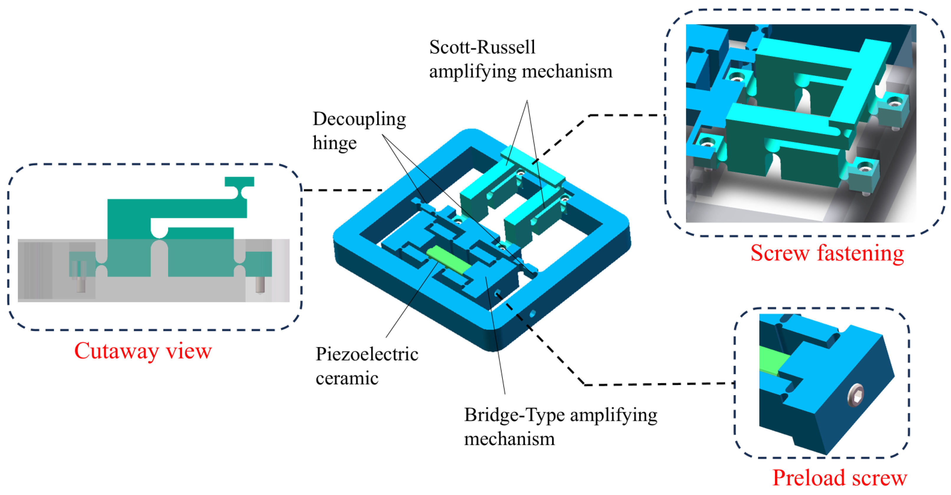
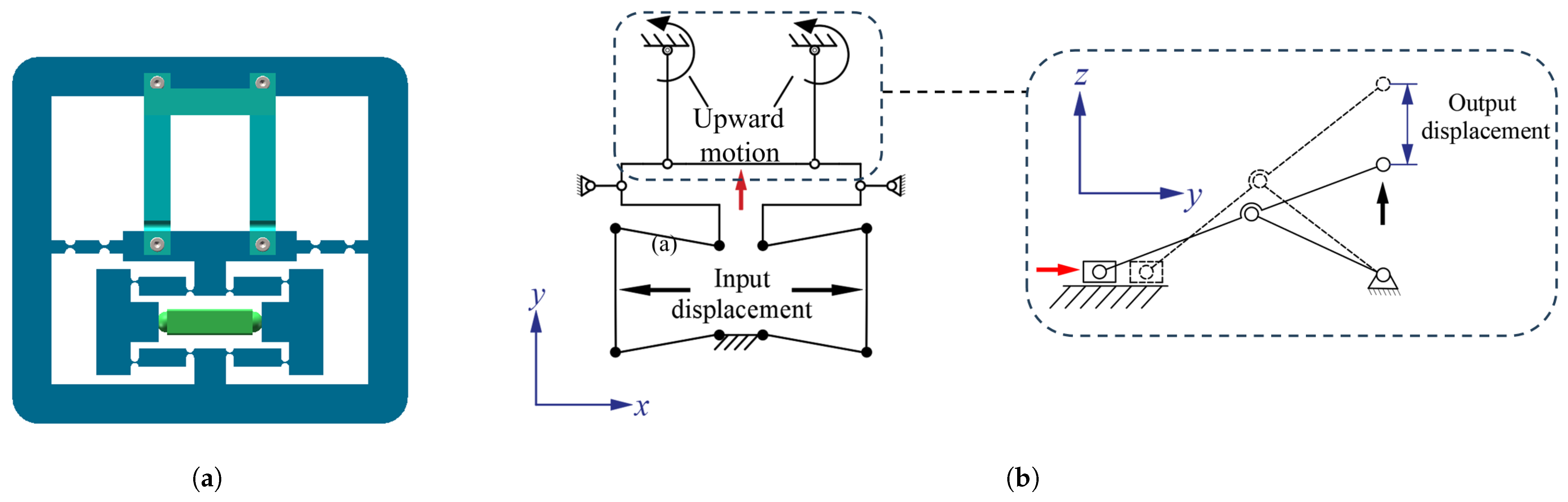
2. Mechanical Design

The designed out-of-plane two-stage displacement amplification mechanism is illustrated in Figure 1. This mechanism comprises a bridge amplification unit based on a plus-guide mechanism, serving as the first-stage drive amplification mechanism, and two Scott–Russell mechanisms functioning as the second-stage displacement amplification output units. The bridge mechanism and the Scott–Russell mechanisms are fastened together using screws, and set screws are provided at the input end of the bridge mechanism to install and preload the piezoelectric ceramic actuator. The design combines the horizontally arranged bridge amplifier mechanism with the external frame into one unit, allowing the system to provide the required amplification effect while maintaining a small height dimension. At the output end of the bridge amplifier, four decoupling hinges have been added to maximize output displacement while maintaining linearity. This configuration aims to minimize non-motion direction parasitic displacements and enhance the output stiffness of the first-stage displacement amplifier. The second-stage displacement amplification mechanism consists of two parallel arranged Scott–Russell mechanisms positioned orthogonally to the first-stage bridge amplification unit. The Scott–Russell mechanism, with a reasonable design of hinge sizes, meets the compactness design in the height direction, further controlling the vertical dimension of the entire mechanism.
As shown in Figure 2a, the piezoelectric actuator serves as a power unit to provide a specific input displacement. Initially, the input displacement is amplified by the first-stage bridge-type amplification mechanism. The resulting output force and displacement are then transmitted to the second-stage Scott–Russell mechanism, which achieves a further displacement amplification while simultaneously transforming the motion direction from in-plane to out-of-plane. The proposed mechanism, therefore, combines two functions: displacement amplification and spatial motion transformation. As illustrated in Figure 2b, the bridge type mechanism performs in-plane amplification, whereas the Scott–Russell mechanism enables vertical motion conversion and amplification. Working together, they form a compact two-stage amplification system that achieves out-of-plane displacement driven by in-plane actuation.

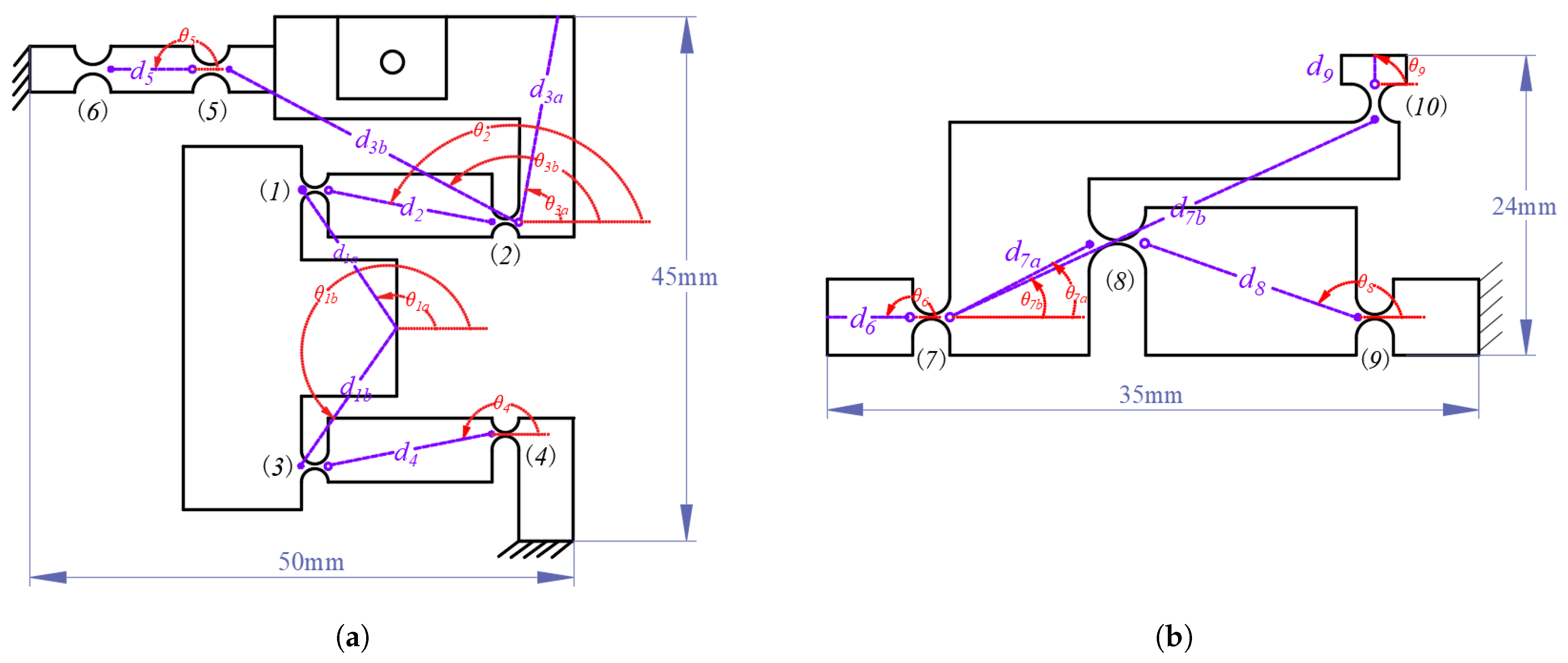
3. Mathematical Modeling

In this section, a kinematic statics model of the mechanism is developed using the matrix method. The intricate kinematic analysis challenges associated with the compliant hinge mechanism are systematically transformed into a matrix representation.
In the following modeling analysis process, several assumptions are made to simplify the analysis: (1) the rigid rods are considered perfectly rigid and do not undergo any deformation; (2) the compliant hinges are assumed to experience small deformations and behave according to linear elastic theory; (3) the center of rotation of each compliant hinge remains at its initial geometric center during deformation.

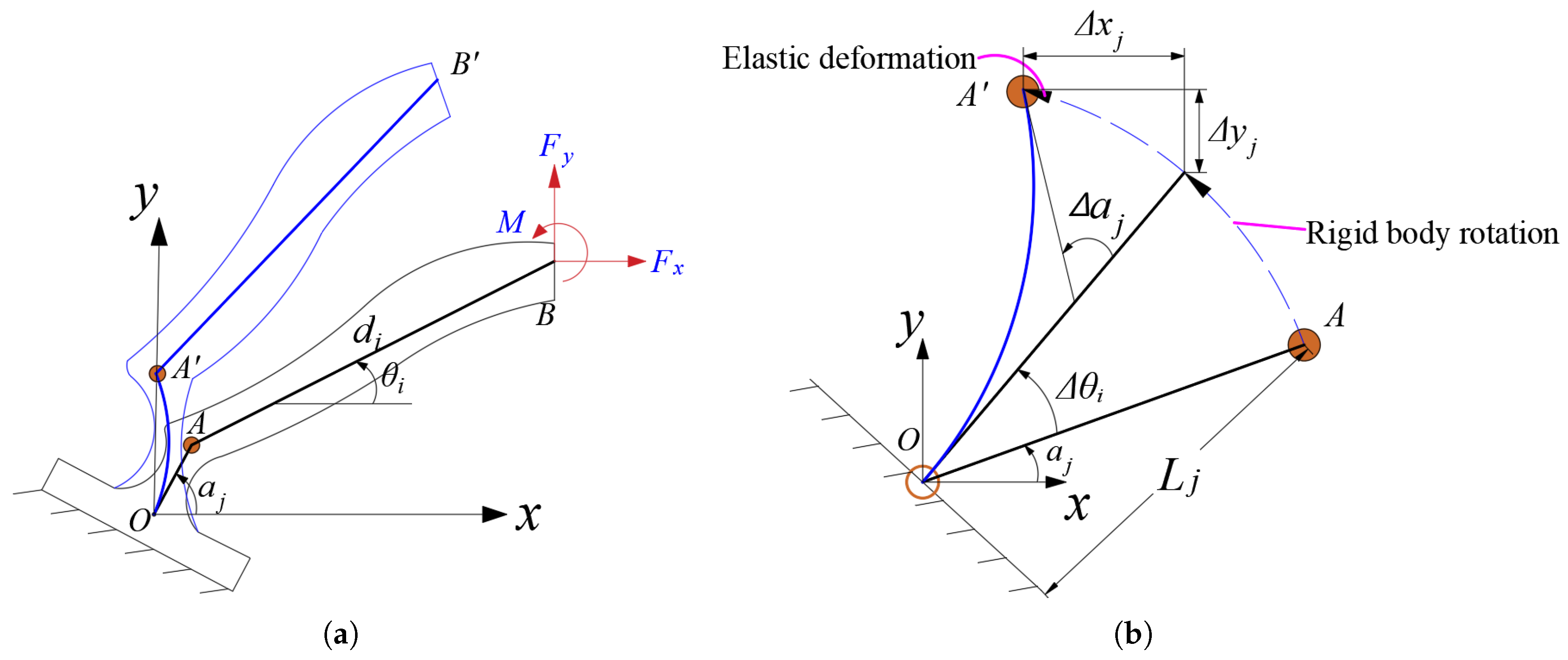
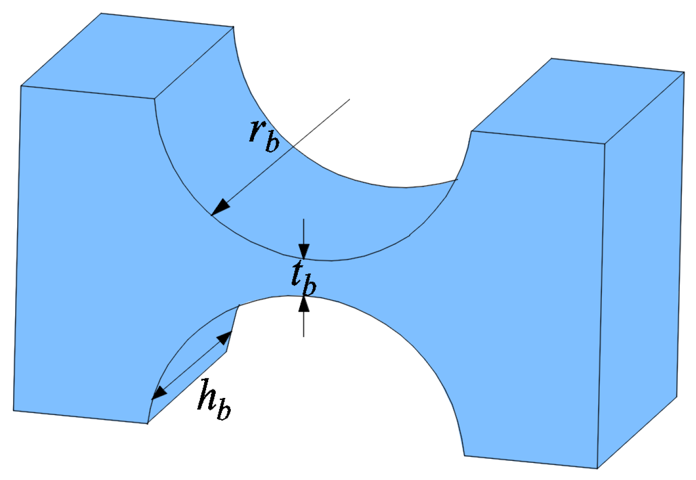
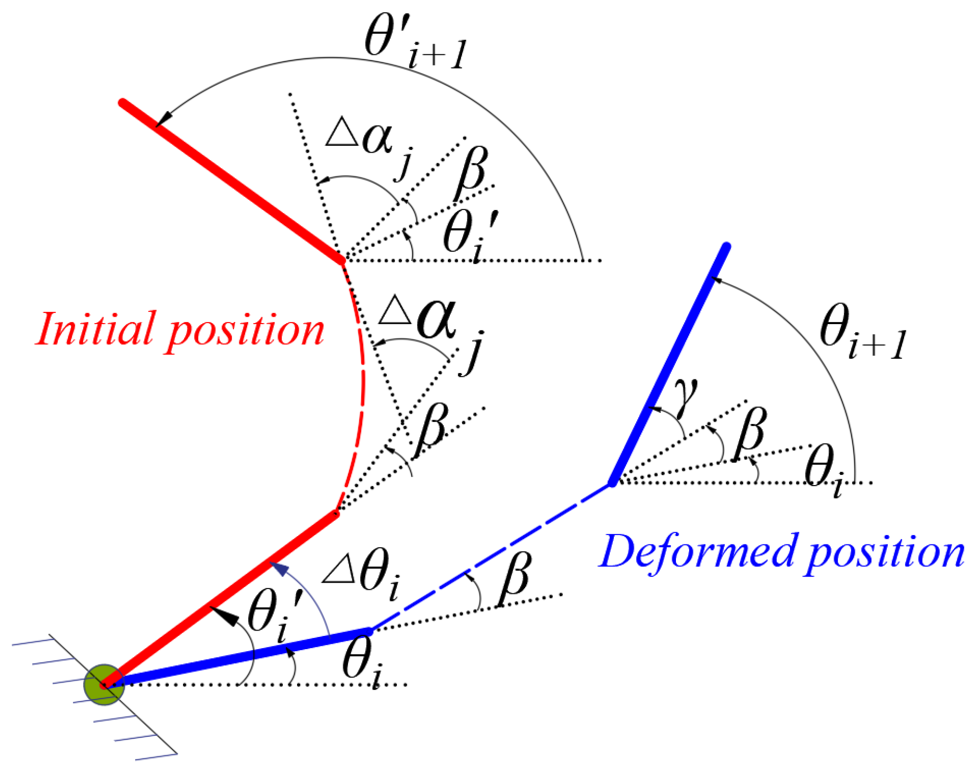
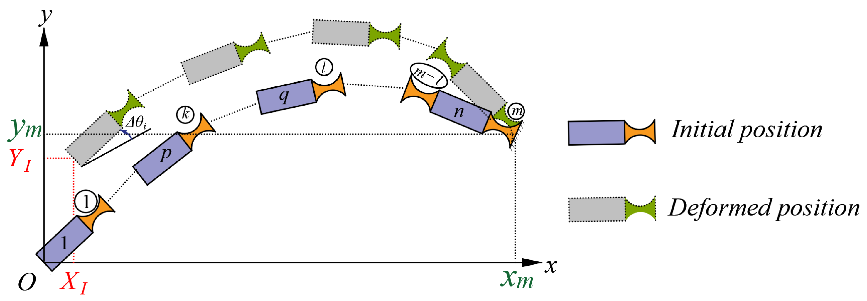
3.1. Constraint Relationship of Rigid Rod-Compliant Hinge

Figure 3 illustrates the constraint relationship for a rigid rod–compliant hinge element. The element, which is subject to an applied load F = [ F x , F y , M ] T at its free end, exhibited an axial displacement along the x-axis, a transverse displacement along the y-axis, and an angular displacement about the z-axis. These deformations are denoted as D = [ Δ x , Δ y , Δ z ] T . The relationship between the deformation of the compliant hinge and the applied load can then be expressed as [4]:
D = C F
The flexibility matrix C of the hinge can be expressed as:
C = c 11 0 0 0 c 22 c 23 0 c 32 c 33
The parameter in the compliance matrix can be calculated as:
c 11 = 1 E h b π r b t b 1 / 2 π 2
c 22 = 9 π r b 5 / 2 2 E h b t b 5 / 2 + 3 π r b 3 / 2 2 E h b t b 3 / 2
c 33 = 9 π r b 1 / 2 2 E h b t b 5 / 2
c 23 = c 32 = 9 π r b 3 / 2 2 E h b t b 5 / 2
where E represents the elastic modulus of the material. h b is the thickness of the compliant hinge, t b is the minimal thickness of compliant hinge, r b is the radius of the circular arc defining the profile of the compliant hinge, as shown in Figure 4.
During the operation of the mechanism, the force-induced deformation of a single compliant hinge–rod element is illustrated in Figure 3a. The initial angles of the rigid rod and the compliant hinge are denoted as θ i and α i , respectively. The dashed line represents the equilibrium position after deformation, while Δ θ i indicates the angular displacement of the rigid rod. The deformation of the compliant hinge, as illustrated in Figure 3b, consists of three components: (1) an angular displacement Δ θ i caused by the rotation of the rigid rod; (2) an angular displacement Δ α j due to rotation about the z-axis, which is perpendicular to the plane; (3) linear displacements Δ x j and Δ y j along the x-axis and y-axis, respectively (representing the elastic deformation displacements of the compliant hinge relative to the position it would reach under pure rigid body rotation of the rigid rod, i.e., the displacement components induced by the bending of the compliant hinge). Therefore, the displacement relationship of the rigid rod and the compliant hinge can be described as follows:
Δ U i = Δ u x i Δ u y i = d i cos ( θ i + Δ θ i ) sin ( θ i + Δ θ i ) d i cos θ i sin θ i
Δ V j = Δ v x j Δ v y j = L j cos ( α j + Δ θ i ) sin ( α j + Δ θ i ) L j cos α j sin α j + Δ x j Δ y j
where Δ U i represents the displacement of the rigid rod from point B to point B , Δ V j represents the displacement of the compliant hinge from point A to point A , d i is the length of the rigid rod, L j is the compliant hinge length.
Figure 5 illustrates the angular displacement relationship between two adjacent rigid rods, denoted as i and i + 1 , which are interconnected by a compliant hinge j. The angular displacement of rigid rod i + 1 can be mathematically expressed as follows:
Δ θ i + 1 = Δ θ i + Δ α j
Figure 6 illustrates a serial compliant hinge mechanism consisting of n rigid rods and m compliant hinges. When the serial compliant hinge mechanism reaches its equilibrium state, moving from the free end O to the fixed end m, the total positional offset accumulated along the rigid and compliant elements must be exactly counterbalanced by the input translation ( X I , Y I ). Through geometric cancellation, the total displacement at the constrained endpoint becomes zero, leading to the following equilibrium equations:
i = 1 n Δ u x i + j = 1 m Δ v x j + X I = 0
i = 1 n Δ u y i + j = 1 m Δ v y j + Y I = 0
where the displacements of adjacent points on the rigid rod are represented by Δ u x i and Δ u y i , while the displacements of adjacent points at the compliant hinge are indicated by v x i and v y i . The displacements of the input end along the x-axis and y-axis are denoted as X I and Y I , respectively.

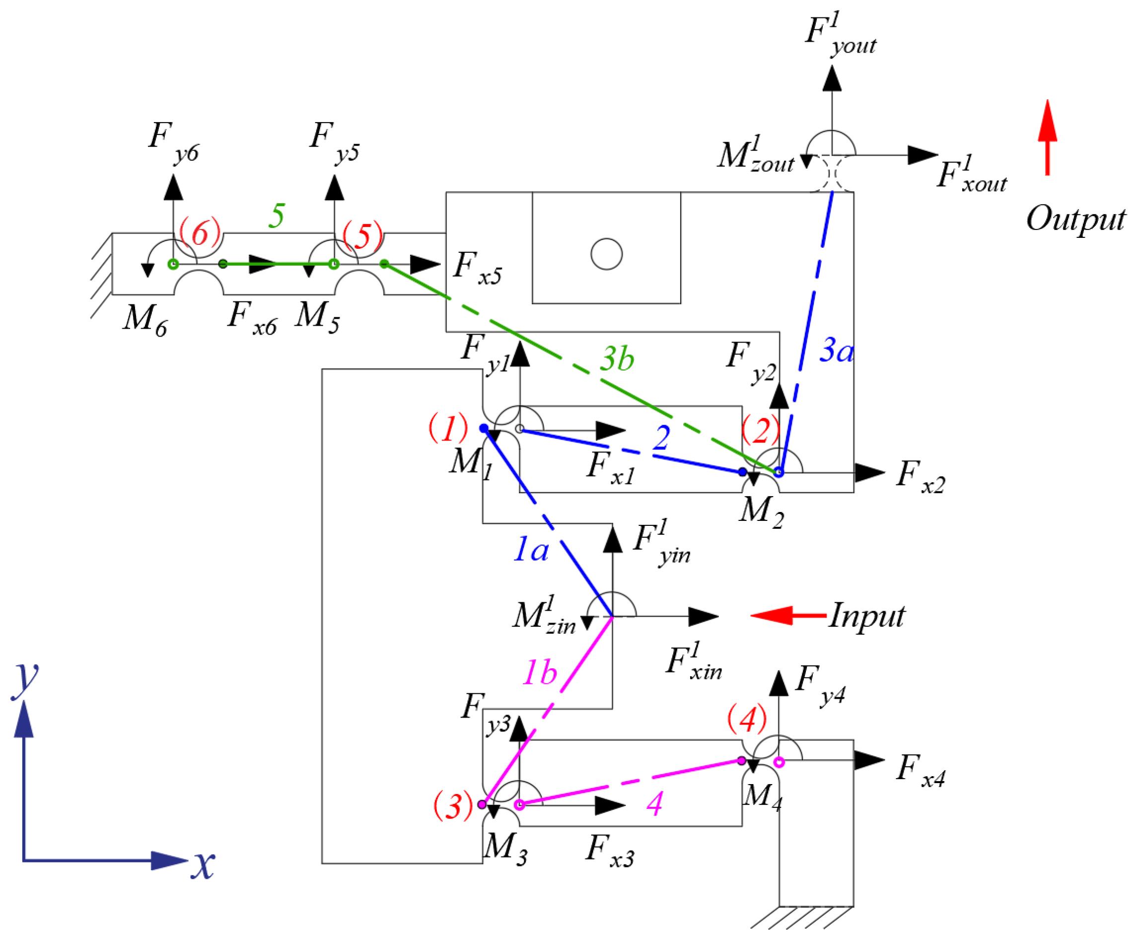
3.2. Bridge-Type Amplification Mechanism

The first-stage bridge-type mechanism exhibits symmetry, allowing for the mechanical analysis to be conducted on only half of the mechanism. When subjected to the action of a piezoelectric ceramic actuator and given a specific input load, the mechanism generates an output load at its output end. The results of this analysis are presented in Figure 7.
The static equilibrium equations can be expressed as:
B v 1 F x 1 + R x 1 = 0
B v 1 F y 1 + R y 1 = 0
B v 1 M 1 B v 1 + F x 1 ( u x 1 + v x 1 ) + B v 1 + F y 1 ( u y 1 + v y 1 ) + M z 1 = 0
where F x 1 , F y 1 , M 1 , R x 1 , R y 1 , and M z 1 represent the load vectors acting on all compliant hinges at the first-stage bridge mechanism including both the virtual compliant hinge and the input terminals. The position vectors of the rigid rod are denoted as u x 1 , u y 1 , while those of the compliant hinge are represented by v x 1 , and v y 1 , with the following parameters:
F x 1 = [ F x 1 F x 2 F x 3 F x 4 F x 5 F x 6 F x o u t 1 ] T F y 1 = [ F y 1 F y 2 F y 3 F y 4 F y 5 F y 6 F y o u t 1 ] T M 1 = [ M 1 M 2 M 3 M 4 M 5 M 6 M z o u t 1 ] T R x 1 = [ F x i n 1 0 0 0 0 ] T R y 1 = [ F y i n 1 0 0 0 0 ] T M z 1 = [ M z i n 1 0 0 0 0 ] T u x 1 = [ u x 1 a u x 1 b u x 2 u x 3 a u x 3 b u x 4 u x 5 ] T u y 1 = [ u y 1 a u y 1 b u y 2 u y 3 a u y 3 b u y 4 u y 5 ] T v x 1 = [ v x 1 v x 2 v x 3 v x 4 v x 5 v x 6 ] T v y 1 = [ v y 1 v y 2 v y 3 v y 4 v y 5 v x 6 ] T
The associated matrix of the compliant hinge mechanism is denoted as B 1 , which represents the relationship between the rigid links and the compliant hinges. B v 1 is the associated matrix for the added virtual hinges, where the virtual matrix is only used for auxiliary matrix calculations and does not bear any load. B v 1 + is the positive association matrix of the mechanism. The associated matrix of the first-stage mechanism can be written as:
B 1 = 1 0 1 0 0 0 1 1 0 0 0 0 0 1 0 1 1 0 0 0 1 1 0 0 0 0 0 0 1 1 B v 1 = 1 0 1 0 0 0 0 1 1 0 0 0 0 0 0 1 0 0 1 0 1 0 0 1 1 0 0 0 0 0 0 0 1 1 0
B v 1 + = 1 0 1 0 0 0 0 0 1 0 0 0 0 0 0 0 0 0 1 0 1 0 0 0 1 0 0 0 0 0 0 0 0 1 0
By substituting Equation (11) along with the incidence matrices B 1 , B v 1 , and B v 1 + into Equations (8)–(10), the force relationship for the first-stage amplification mechanism can be obtained.
The force equilibrium equation along the x-axis is presented as follows:
F x 1 + F x 3 + F x i n 1 = 0
F x 1 + F x 2 = 0
F x 2 + F x 5 + F x o u t 1 = 0
F x 3 + F x 4 = 0
F x 5 + F x 6 = 0
The force equilibrium equation along the y-axis is presented as follows:
F y 1 + F y 3 + F y i n 1 = 0
F y 1 + F y 2 = 0
F y 2 + F y 5 + F y o u t 1 = 0
F y 3 + F y 4 = 0
F y 5 + F y 6 = 0
The torque equilibrium equation for rotation about the z-axis is:
M 1 + M 3 + M z i n 1 + F y 1 ( u y 1 a + v y 1 ) + F y 3 ( u y 2 + v y 3 ) + F y o u t 1 u y 5 F x 1 ( u x 1 a + v x 1 ) F x 3 ( u x 2 + v x 3 ) F x o u t 1 u x 5 = 0
M 1 + M 2 + F y 2 ( u y 1 b + v y 2 ) F x 2 ( u x 1 b + v x 2 ) = 0
M 2 + M 5 + M z o u t 1 + F y 5 ( u y 3 b + v y 5 ) + F y o u t 1 u y 5 F x 5 ( u x 3 b + v x 5 ) F x o u t 1 u x 5 = 0
M 3 + M 4 + F y 4 ( u y 3 a + v y 4 ) F x 4 ( u x 3 a + v x 4 ) = 0
M 5 + M 6 + F y 6 ( u y 4 + v y 6 ) F x 6 ( u x 4 + v x 6 ) = 0
Equations (12)–(26) represent the equilibrium equations of each rigid rod element in the x-axis, y-axis, and z-axis. Specifically, Equation (12) describes the force equilibrium state of rigid rod 1 in the x-direction. Since it is connected to compliant hinges (1) and (3), according to the principle of action and reaction, the resultant force acting on rigid rod 1 along the x-axis must be zero. Similarly, Equations (13)–(26) represent the force equilibrium equations and moment equilibrium equations of rigid rods 2 to 5 in the y-axis and z-axis.
Following the establishment of the force equilibrium relationships, the path from the input end to the output end, or from the input end to the fixed end, is described by a geometric constraint equation to characterize the displacement transmission within the mechanism. Figure 7 illustrates three distinct paths of the first-stage bridge mechanism: 1a-(1)-2-(2)-3a, 1a-(1)-2-(2)-3b-(5)-5-(6), and 1b-(3)-4-(4). The corresponding geometric equations can be expressed as follows:
P 1 Δ u x 1 Δ v x 1 + W x 1 = Q x 1 P 1 Δ u y 1 Δ v y 1 + W y 1 = Q y 1
where P 1 is the path matrix, representing the connection path from the rigid rods to the compliant hinges, describing the transmission path either from the input to the output or from the input to the fixed end:
P 1 = 1 0 1 1 0 0 0 1 1 0 0 0 0 1 0 1 0 1 0 1 1 1 0 0 1 1 0 1 0 0 0 1 0 0 0 1 1 0 0
where Δ u x 1 , Δ u y 1 and Δ v x 1 , Δ v y 1 are the displacement vectors of the rigid rod and compliant hinge of the first-stage bridge mechanism. W x 1 , W y 1 and Q x 1 , Q y 1 are the displacement vectors of the input and output ends, respectively, with the following parameters:
Δ u x 1 = Δ u x 1 a Δ u x 1 b Δ u x 2 Δ u x 3 a Δ u x 3 b Δ u x 4 Δ u x 5 T Δ v x 1 = Δ v x 1 Δ v x 2 Δ v x 3 Δ v x 4 Δ v x 5 Δ v x 6 T Δ u y 1 = Δ u y 1 a Δ u y 1 b Δ u y 2 Δ u y 3 a Δ u y 3 b Δ u y 4 Δ u y 5 T Δ v y 1 = Δ v y 1 Δ v y 2 Δ v y 3 Δ v y 4 Δ v y 5 Δ v y 6 T W x 1 = X i n 1 X i n 1 X i n 1 T W y 1 = Y i n 1 Y i n 1 Y i n 1 T Q x 1 = X o u t 1 0 0 T Q y 1 = Y o u t 1 0 0 T
where X i n 1 and Y i n 1 are the displacement components at the input terminal, while X o u t 1 and Y o u t 1 are the displacement components at the output terminal. By substituting Equation (28) into Equation (27), the geometric relationship governing the first-stage amplification mechanism can be derived.
The geometric constraint equation in the x-axis direction is formulated as follows:
Δ u x 1 a + Δ u x 2 + Δ u x 3 a + Δ v x 1 + Δ v x 2 + X i n 1 = X o u t 1
Δ u x 1 a + Δ u x 2 + Δ u x 3 b + Δ u x 5 + Δ v x 1 + Δ v x 2 + Δ v x 5 + Δ v x 6 + X i n 1 = 0
Δ u x 1 b + Δ u x 4 + Δ v x 3 + Δ v x 4 + X i n 1 = 0
The geometric constraint equation in the y-axis direction is formulated as follows:
Δ u y 1 a + Δ u y 2 + Δ u y 3 a + Δ v y 1 + Δ v y 2 + Y i n 1 = Y o u t 1
Δ u y 1 a + Δ u y 2 + Δ u y 3 b + Δ u y 5 + Δ v y 1 + Δ v y 2 + Δ v y 5 + Δ v y 6 + Y i n 1 = 0
Δ u y 1 b + Δ u y 4 + Δ v y 3 + Δ v y 4 + Y i n 1 = 0
Equations (29)–(34) represent the displacement relationships of the flexible hinges and rigid rods in the x-axis and y-axis. Specifically, Equation (29) describes the displacement relationship of the flexible hinges and rigid rods along the x-axis in path 1a-(1)-2-(2)-3a. Equations (30)–(31) correspond to the displacement relationships along the x-axis in paths 1a-(1)-2-(2)-3b-(5)-5-(6) and 1b-(3)-4-(4). Similarly, Equations (32)–(34) represent the displacement transmission relationships of the flexible hinges and rigid rods in the y-axis.
Following the identification of the displacement transmission paths, the angular displacement relationships of the first-stage displacement amplification mechanism are modeled. The corresponding angular displacement matrix can be expressed as:
B 1 T Δ θ 1 + Δ α 1 = 0
where Δ θ 1 is the angular displacement vector of the rigid rods, which can be expressed as Δ θ 1 = [ Δ θ 1 , Δ θ 2 , Δ θ 3 , Δ θ 4 , Δ θ 5 ] T , Δ α 1 is the angular displacement vector of the compliant hinges, which can be expressed as Δ α 1 = [ Δ α 1 , Δ α 2 , Δ α 3 , Δ α 4 , Δ α 5 , Δ α 6 ] T . By substituting the above parameters Δ θ 1 , Δ α 1 can be brought into Equation (35) to obtain the angular displacement relationship of the second-stage displacement amplification mechanism. The angular displacement matrix for the bridge-type mechanism is presented as follows:
Δ θ 1 Δ θ 2 + Δ α 1 = 0
Δ θ 2 Δ θ 3 + Δ α 2 = 0
Δ θ 1 Δ θ 4 + Δ α 3 = 0
Δ θ 3 Δ θ 4 + Δ α 4 = 0
Δ θ 3 Δ θ 5 + Δ α 5 = 0
Δ θ 5 + Δ α 3 = 0
Equations (36)–(41) represent the angular displacement relationships between the rigid rods and the compliant hinges during the rotational deformation process. Specifically, Equation (36) describes the connection between rigid rod 1 and rigid rod 2 through compliant hinge (1), where the difference in angular displacement and the angular deformation of the hinge must sum to zero. Similarly, Equations (37)–(41) also satisfy the angular displacement constraint relationships.

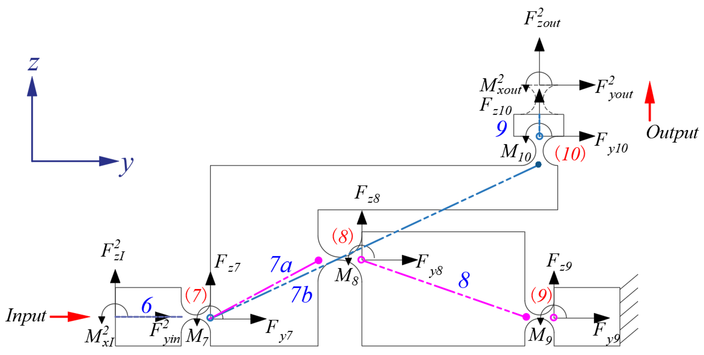
3.3. Scott–Russell Amplification Mechanism

The second-stage amplification mechanism of the two-stage displacement amplifier is composed of two identical Scott–Russell mechanisms placed in parallel. Therefore, only one Scott–Russell mechanism is selected for mechanical analysis, using the same method as that applied to the first-stage amplification mechanism. The results of its force and path analysis are shown in Figure 8:
Similarly, the static equilibrium equations for the second-stage Scott–Russell mechanism are expressed as:
B v 2 F y 2 + R y 2 = 0
B v 2 F z 2 + R z 2 = 0
B v 2 M 2 B v 2 + F y 2 ( u y 2 + v y 2 ) + B v 2 F z 2 ( u z 2 + v z 2 ) + M x 2 = 0
where F y 2 , F z 2 , M 2 , R y 2 , R z 2 , M x 2 represent the load vectors acting on all compliant hinges at the second-stage Scott–Russell mechanism, including both the virtual compliant hinge and the input terminals. The position vectors of the rigid rod are denoted as u y 2 , u z 2 , while those of the compliant hinge are represented by v y 2 , and v z 2 , with the following parameters:
F y 2 = F y 7 F y 8 F y 9 F y 10 F y o u t 2 T F z 2 = F z 7 F z 8 F z 9 F z 10 F z o u t 2 T M 2 = M 7 M 8 M 9 M 10 M x o u t 2 T R y 2 = F y i n 2 0 0 0 T R z 2 = F z i n 2 0 0 0 T M x 2 = M x i n 2 0 0 0 T u y 2 = u y 6 u y 7 a u y 7 b u y 8 u y 9 T u z 2 = u z 6 u z 7 a u z 7 b u z 8 u z 9 T v y 2 = v y 7 v y 8 v y 9 v y 10 T v z 2 = v z 7 v z 8 v z 9 v z 10 T
The incidence matrix of the second-stage Scott–Russell mechanism can be written as:
B 2 = 1 0 0 0 1 1 0 1 0 1 1 0 0 0 0 1 B v 2 = 1 0 0 0 0 1 1 0 1 0 0 1 1 0 0 0 0 0 1 1 B v 2 + = 1 0 0 0 0 1 0 1 0 0 0 0 0 1 0 0 0 0 0 1
By substituting Equation (45) along with the incidence matrices B 2 , B v 2 , B v 2 + into Equations (42)–(44), the force–displacement relationship for the second-stage amplification mechanism can be obtained.
The force equilibrium equation along the y-axis is presented as follows:
F y 7 + F y i n 2 = 0
F y 7 + F y 8 F y 10 = 0
F y 8 + F y 9 = 0
F y 10 F y o u t 2 = 0
The force equilibrium equation along the z-axis is presented as follows:
F z 7 + F z i n 2 = 0
F z 7 + F z 8 F z 10 = 0
F z 8 + F z 9 = 0
F z 10 F z o u t 2 = 0
The torque equilibrium equation for rotation about the x-axis is:
M 7 F y 7 ( u y 6 + v y 7 ) + F z 7 ( u z 6 + v z 7 ) + M x i n 2 = 0
M 7 + M 8 + M 10 F y 8 ( u y 7 a + v y 8 ) F y 10 ( u y 8 + v y 10 ) + F z 8 ( u z 7 a + v z 8 ) F z 10 ( u z 8 + v z 10 ) = 0
M 8 + M 9 F y 9 ( u y 7 b + v y 9 ) + F z 9 ( u z 7 b + v z 9 ) = 0
M 10 + M x o u t 2 F y o u t 2 u y 9 + F z o u t 2 u z 9 = 0
Figure 8 illustrates the second-stage paths associated with the two output paths of Scott–Russell: 1-(1)-2a-(2)-3-(3), and 1-(1)-2-(4)-4b. The corresponding geometric equation can be articulated as follows:
P 2 Δ u y 2 Δ v y 2 + W y 2 = Q y 2 P 2 Δ u z 2 Δ v z 2 + W z 2 = Q z 2
where Δ u y 2 , Δ u z 2 and Δ v y 2 , Δ v z 2 are the displacement vectors of the rigid rod and compliant hinge of the second-stage Scott–Russell mechanism. W y 2 , W z 2 and Q y 2 , Q z 2 are the displacement vectors of the input and output ends, respectively, and P 2 is the path matrix, with the following parameters:
P 2 = 1 1 1 1 0 1 1 0 0 1 1 0 0 1 0 0 1 1
Δ u y 2 = Δ u y 6 Δ u y 7 a Δ u y 7 b Δ u y 8 Δ u y 9 T Δ v y 2 = Δ v y 7 Δ v y 8 Δ v y 9 Δ v y 10 T Δ u z 2 = Δ u z 6 Δ u z 7 a Δ u z 7 b Δ u z 8 Δ u z 9 T Δ v z 2 = Δ v z 7 Δ v z 8 Δ v z 9 Δ v z 10 T W y 2 = Y i n 2 Y i n 2 T W z 2 = Z i n 2 Z i n 2 T Q y 2 = Y o u t 2 0 T Q z 2 = Z o u t 2 0 T
where Y i n 2 and Z i n 2 are the displacement components at the input terminal, while Y o u t 2 and Z o u t 2 are the displacement components at the output terminal. Similarly, by substituting Equation (59) into Equation (58) the geometric relationship of the second-order amplification mechanism can be derived.
The geometric constraint equation in the y-axis direction is formulated as follows:
Δ u y 6 + Δ u y 7 a + Δ u y 7 b + Δ u y 8 + Δ v y 7 + Δ v y 8 + Y i n 2 = 0
Δ u y 6 + Δ u y 7 a + Δ u y 9 + Δ v y 9 + Δ v y 10 + Y i n 2 = Y o u t 2
The geometric constraint equation in the z-axis direction is formulated as follows:
Δ u z 6 + Δ u z 7 a + Δ u z 7 b + Δ u z 8 + Δ v z 7 + Δ v z 8 + Z i n 2 = 0
Δ u z 6 + Δ u z 7 a + Δ u z 9 + Δ v z 9 + Δ v z 10 + Z i n 2 = Z o u t 2
The angular displacement matrix of the second-stage Scott–Russell mechanism can be expressed as:
B T 2 Δ θ 2 + Δ α 2 = 0
where Δ θ 2 is the angular displacement vector of the rigid rods in the second-stage displacement amplification mechanism, which can be expressed as Δ θ 2 = [ Δ θ 6 , Δ θ 7 , , Δ θ 9 ] T , Δ α 2 is the angular displacement vector of the compliant hinges in the second-stage displacement amplification mechanism, which can be expressed as Δ α 2 = [ Δ α 7 , α 8 , , Δ α 10 ] T . Substituting the above parameters Δ θ 2 , Δ α 2 can be brought into Equation (64) to obtain the angular displacement relationship of the second-stage displacement amplification mechanism. The angular displacement matrix for the Scott–Russell mechanism is presented as follows:
Δ θ 7 + Δ α 7 = 0
Δ θ 9 + Δ θ 8 Δ θ 7 + Δ α 8 = 0
Δ θ 9 Δ θ 8 + Δ α 9 = 0
Δ α 10 Δ θ 10 = 0

3.4. Two-Stage Displacement Amplification Mechanism

After completing the modeling and analysis of the first-stage and second-stage amplification mechanisms, the overall force-displacement relationship of the two-stage mechanism is analyzed next. The output of the first stage of the two-stage displacement amplifier, the bridge displacement amplifier, is connected to the inputs of the two second-stage Scott–Russell mechanisms. As shown in Figure 7 and Figure 8, the following force–displacement relationships are established:
Y o u t 1 = Y i n 2
F y o u t 1 = F y i n 2
In practical applications, given the input displacement X i n 1 and the output force F z o u t 2 , the overall static equilibrium equations can be established. By combining the static equilibrium equations of the bridge and Scott–Russell mechanisms Equations (8)–(10) and (42)–(44), the geometric constraint equations Equations (27) and (58), and the angular displacement matrices Equations (35) and (64), and assuming no loads at the outputs, the kinematic–static model of the two-stage amplification mechanism can be derived based on Equations (69) and (70). This model characterizes the amplification ratio R a m p , the input stiffness K i n , and the equivalent stiffness K e q of the two-stage amplification mechanism:
R a m p = Z o u t 2 2 X i n 1
K i n = F x i n 1 X i n 1
K e q = F z o u t 2 X i n 1

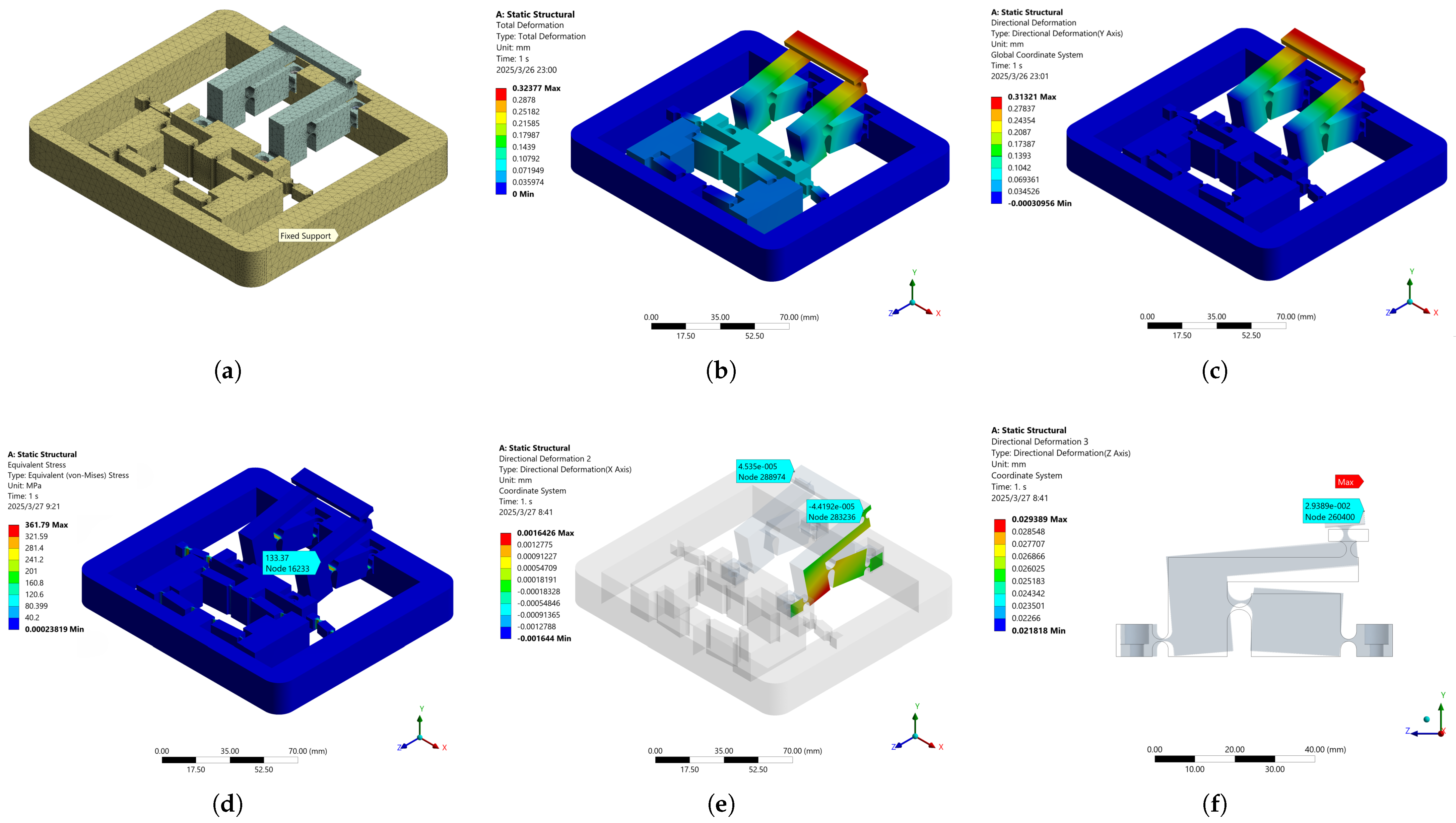
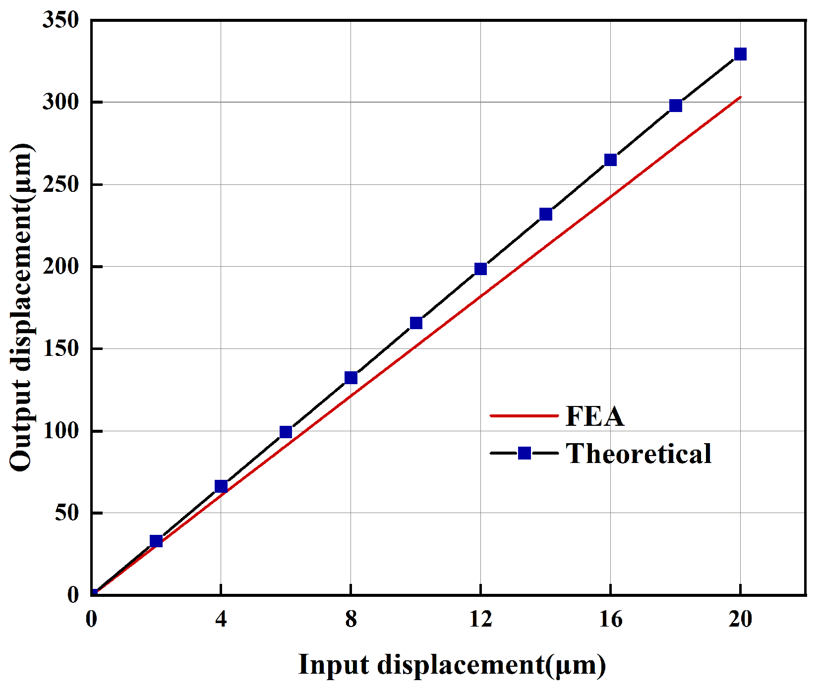
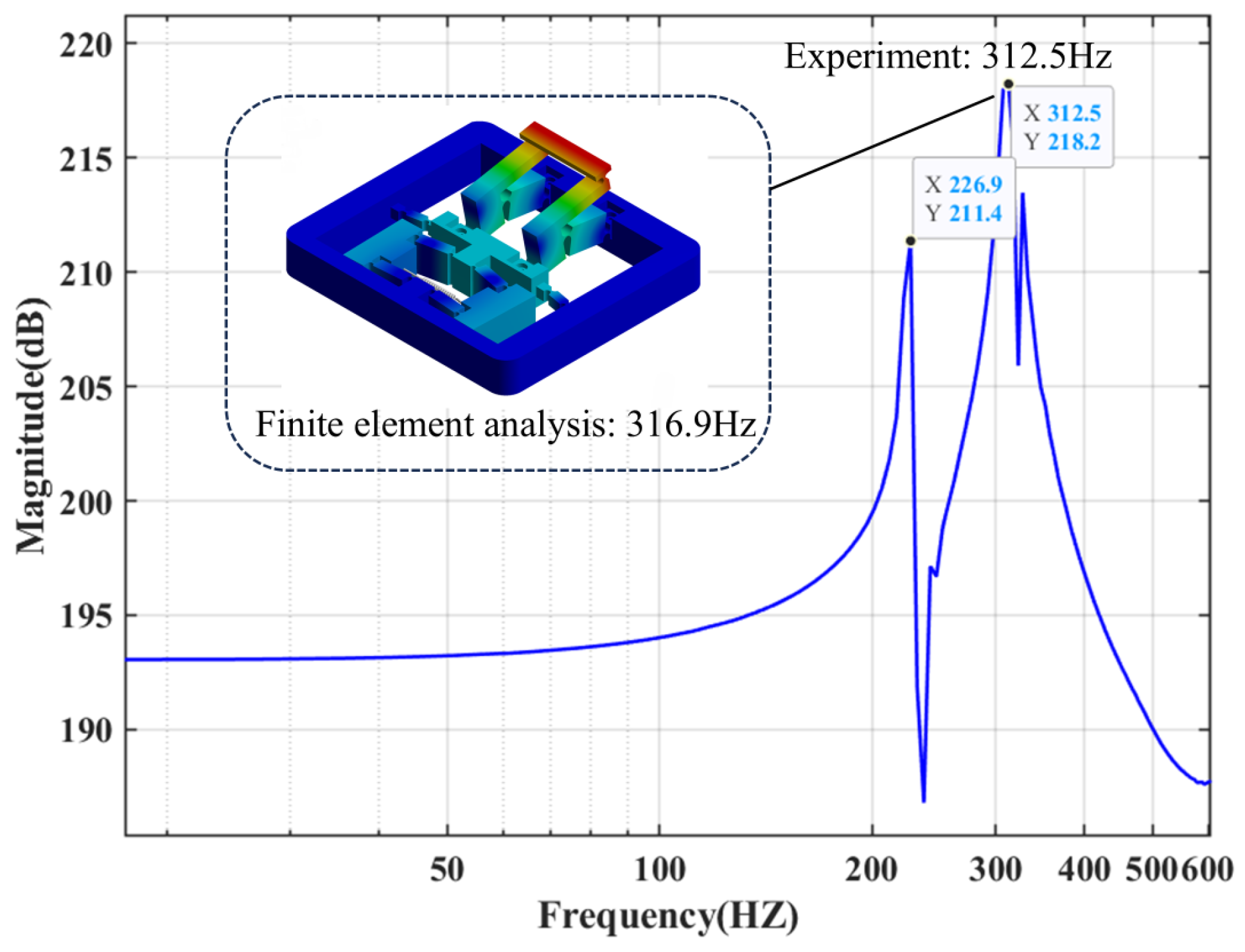
4. Finite Element Simulation and Analysis

In order to evaluate the mechanical properties of the proposed two-stage displacement amplification mechanism and to verify the accuracy of the established kinematic model, finite element analysis was conducted using Ansys Workbench 2022 R2 software. The first-stage bridge-type mechanism and the second-stage Scott–Russell mechanism are both fabricated from A L 7075 for simulation purposes. The material parameters of the mechanism is summarized in Table 1, and the geometric parameters are summarized in Table 2 and Table 3. The geometric parameter labeling of the two mechanisms is shown in Figure 9. Figure 10 presents the deformation contour map derived from the static finite element analysis conducted in Ansys Workbench.
As illustrated in Figure 10a, a fixed support is applied at the bottom of the mechanism to constrain the degrees of freedom of its base surface. To improve simulation accuracy, local mesh refinement is performed in the compliant hinge regions. The finite element model is discretized using tetrahedral elements, with a mesh element size of 0.3 mm in the hinge regions and 0.5 mm in the other regions. The entire model consists of approximately 358,450 nodes and 203,605 elements. During the simulation, the boundary conditions include a fixed constraint at the bottom and an imposed displacement load of 10 μm at each of the two input terminals. The total deformation cloud diagram is shown in Figure 10b, indicating that the total output displacement of the mechanism reaches 323.8 μm. The displacement in the primary motion direction is presented in Figure 10c, where the output displacement along the y-axis is 313.4 μm. The stress distribution within the mechanism is illustrated in Figure 10d, revealing that the maximum stress occurs at the deformed region of the compliant hinge, reaching 133.3 Mpa. This value remains well below the allowable stress limit of 270 Mpa for the A L 7075 material, thus satisfying the structural safety requirements. Furthermore, Figure 10e shows the parasitic translational displacement along the non-primary x-axis direction, with a maximum value of 0.04 μm. Figure 10f displays the parasitic rotational displacement around the x-axis, reaching a maximum of 29.4 μm. Based on the geometrical configuration, the corresponding parasitic angular displacement at the output end is calculated to be approximately 97 μrad. These results demonstrate that the parasitic motion has a negligible effect on the primary output motion, indicating that the mechanism exhibits excellent mechanical performance.
Figure 11 illustrates that the magnification ratio derived from finite element analysis is 16.31, which exhibits a 3.1% discrepancy compared to the value obtained from the kinematic model. Input forces of varying magnitudes are applied, and the corresponding input and output displacements are recorded, as presented in Figure 12. Specifically, Figure 12a illustrates that the input stiffness obtained from FEA simulation is 9.26 N/ μ m, which deviates by 2.1% from the theoretical input stiffness. Figure 12b illustrates the relationship between the input force and the output displacement. The primary discrepancy between the theoretical and simulation results can be attributed to the assumption in the theoretical model that the center of rotation of the compliant hinge remains at its geometric center and does not change with motion. In contrast, FEA accounts for the dynamic shift in the center of rotation as the compliant hinge moves.
Further finite element analysis was conducted to evaluate the dynamic performance of the two-stage displacement amplification mechanism, with the results presented in Figure 13. In the analysis, the piezoelectric actuator was formed as a linear spring with stiffness identical to its effective stiffness. This study focuses on the first four vibration modes of the mechanism. The first mode, as illustrated in Figure 13a, represents the deformation in the direction of output displacement, with a frequency of 316.9 Hz, which is consistent with the mechanism’s intended operating direction. The second mode, shown in Figure 13b, reflects the lateral deformation at the output end of the mechanism, with a frequency of 905.7 Hz. The third mode, presented in Figure 13c, corresponds to the deformation at the connection between the two amplification stages, with a frequency of 969.7 Hz. The fourth mode, as shown in Figure 13d, describes the rotational deformation of the two displacement amplification mechanisms, with a corresponding frequency of 1540.9 Hz. The relatively high first-order natural frequency compared to the second-order natural frequency indicates that the displacement amplification mechanism exhibits excellent dynamic characteristics, effectively suppressing undesired vibrations and ensuring stable and reliable performance under dynamic operating conditions.

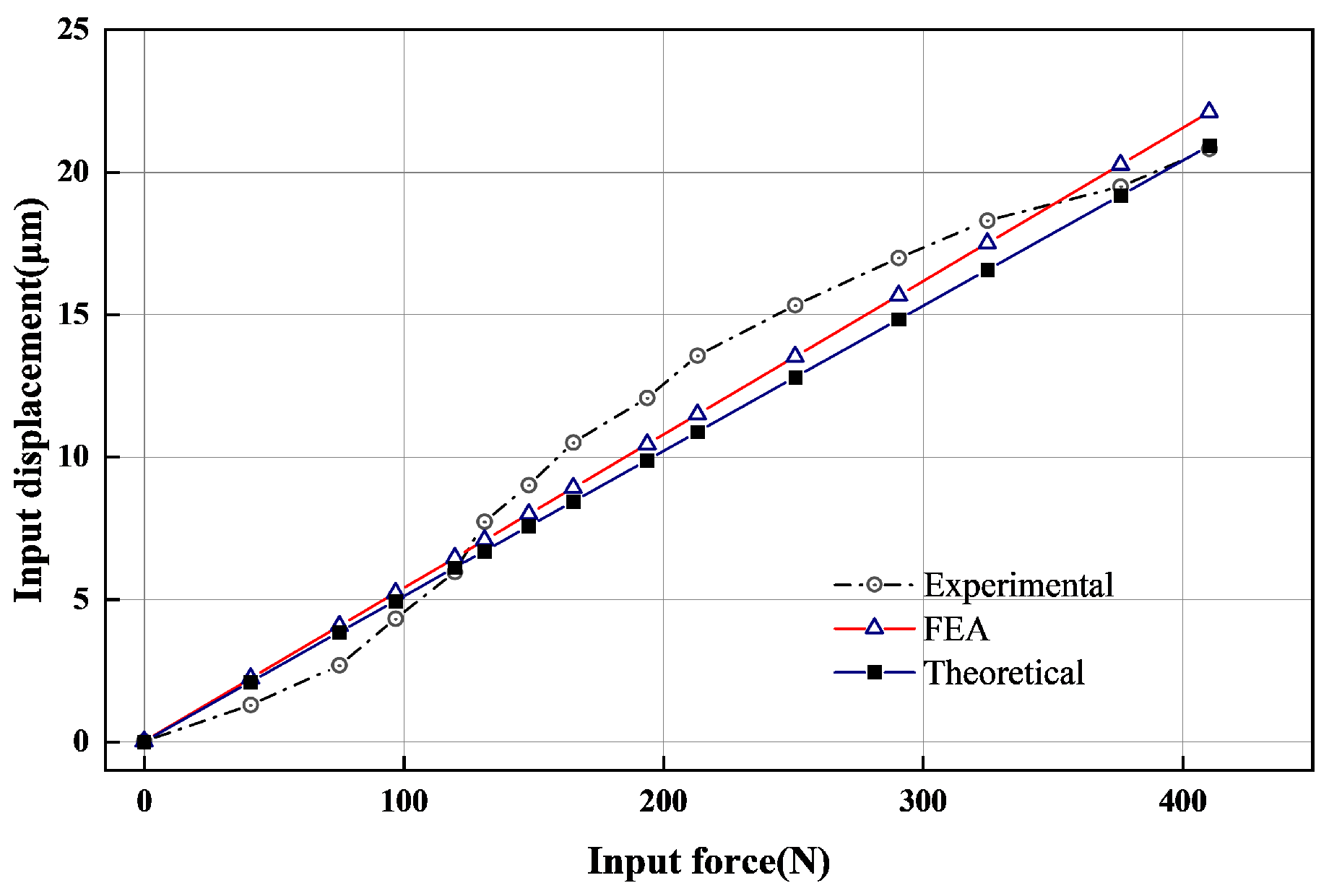
5. Experimental Validation

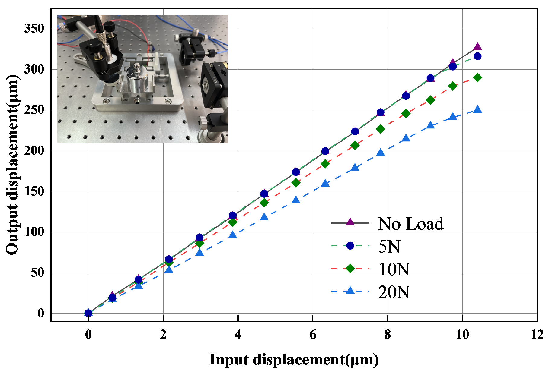
5.1. Prototype Production and Experimental Platform Construction

To experimentally evaluate the performance of the two-stage displacement amplification mechanism and validate the precision of the kinematic model, an experimental apparatus, as illustrated in Figure 14, is designed and manufactured. To ensure the reliability and repeatability of the experimental results, all experiments were conducted under standard laboratory conditions. The assembled experimental setup is installed on an air-bearing platform to interface with other components. A piezoelectric actuator (7 mm × 7 mm × 30 mm, model D C S 3070730 C 2 ) is used to drive the mechanism. The piezoelectric actuator has a maximum driving voltage of 150 V, a maximum output displacement of 34.0 μ m ± 15%, a maximum output force of 1960 N, and a stiffness of 57 N/ μ m. During the input control process, the computer serves as the host device, where specialized software is used to set the output waveform parameters and send control commands to the power source and controller. Subsequently, the controller generates and amplifies a triangular voltage signal with an amplitude of 150 V, which is applied to the piezoelectric actuator to achieve displacement input.
The displacements at both the input and output ends were measured using laser interferometric displacement sensors ( I D S 3010 Interferometric Sensor, attocube systems AG, Munich, Germany). These sensors offer a measurement range of 0 to 5000 mm, a maximum resolution of 0.02 pm, and a maximum sampling period of 1 ms. To achieve non-contact high-precision measurements, reflecting telescopes were affixed to the input end, output end, and transverse direction of the output end of the mechanism. The laser beams were reflected back from the reflecting telescope to the sensors, enabling the detection of displacement changes at the corresponding locations. Specifically, Laser Sensor 1 was assigned to measure the primary output displacement, Laser Sensor 2 measured the input displacement, and Laser Sensor 3 captured the transverse parasitic displacement at the output end.

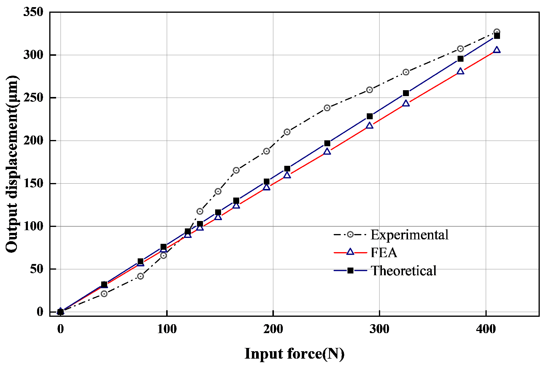
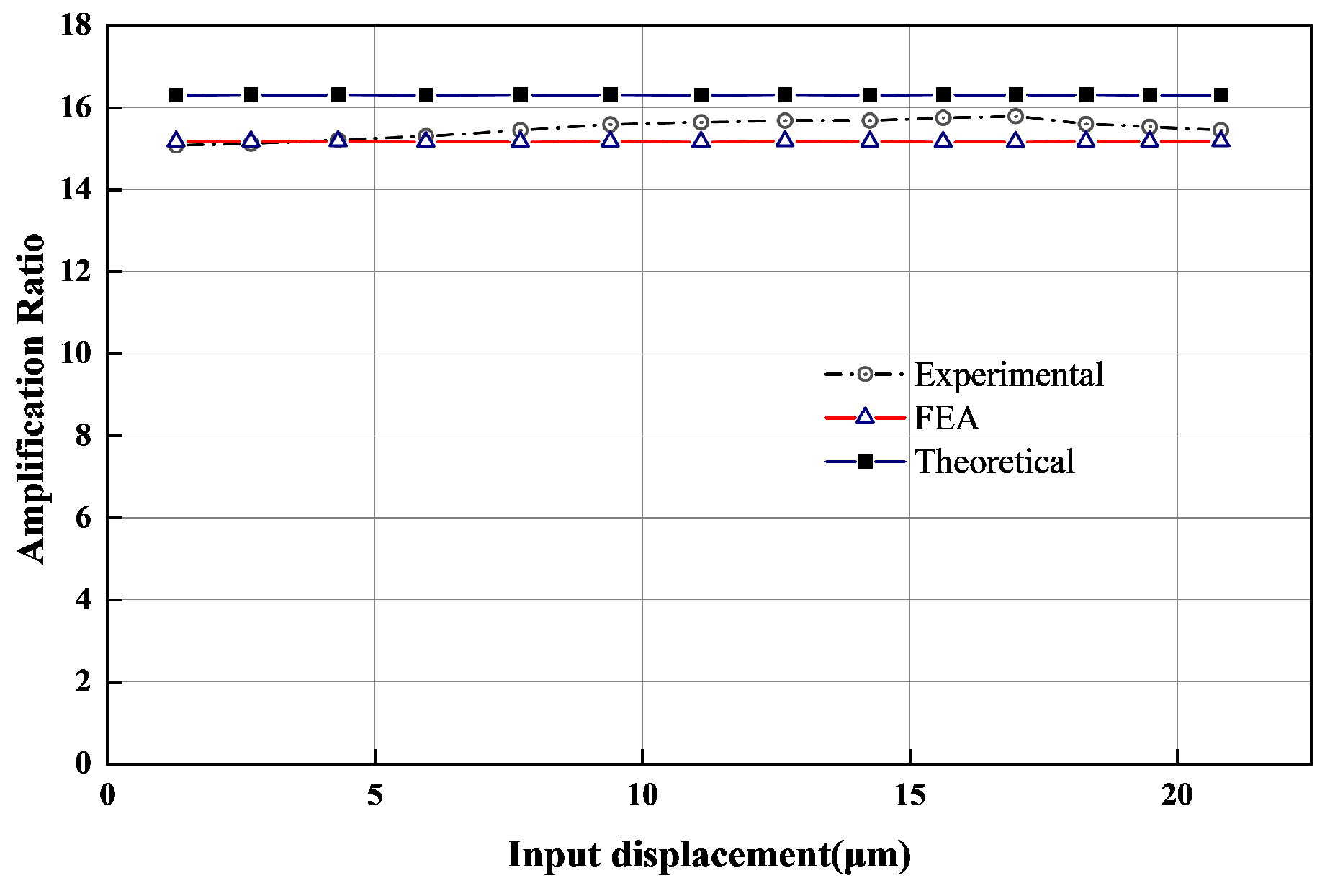
5.2. Mechanical Performance Test

Figure 15 illustrates the displacement curves in both the vertical and parasitic directions under input displacements ranging from 0 to 21 μ m. The experimental results demonstrate a strong linear relationship between the input and output displacements. When the input displacement reaches 21 μ m, the maximum vertical output displacement reaches 331.23 μ m, corresponding to an amplification ratio of 15.70, with a deviation of 4.6% from the theoretical value. Furthermore, the maximum translational parasitic displacement is only 0.42 μ m, and the maximum rotational parasitic displacement is 76.8 μ rad, which represents a sufficiently large margin relative to the output displacement. The slight deviations between the theoretical and experimental results are mainly attributed to machining and assembly errors of the mechanism components, as well as environmental disturbances during the experiments.
By leveraging the relationship between the force and displacement of the piezoelectric ceramic, we can derive the input force and analyze the changes in both input and output displacements. Figure 16 illustrates the relationship between the input force and the input displacement of the mechanism. The experimental data indicate that the input stiffness is measured at 17.75 N/ μ m, with an associated error of 9.9% when compared to the theoretical value.
Figure 17 illustrates the relationship between the input force and output displacement of the mechanism. The experimental data indicate that the equivalent stiffness is measured at 1.16 N/ μ m, with an associated error of 6.4% when compared to the theoretical value.
Figure 18 indicates that the amplification ratio of the displacement amplification mechanism remains constant. The experimental data indicate that the amplification ratio is measured at 15.70, with an associated error of 4.6% when compared to the theoretical value.
The analysis of both experimental and theoretical results is presented in Table 4. The discrepancies between the theoretical and experimental results can be attributed to factors such as machining accuracy, assembly errors, and external environmental interference.
To evaluate the loading performance of the amplification mechanism in the experimental setup, Figure 19 illustrates the output displacement tests conducted by applying different weights to the mechanism. The results indicate that the amplification ratio decreases as the load increases. Specifically, at a load of 5 N, the amplification ratio is 15.67. At a load of 10 N, this ratio decreases to 14.40. At a load of 20 N, the amplification ratio further reduces to 12.51, which is lower than the no-load amplification ratio of 15.70. These results indicate that the mechanism demonstrates high output stiffness.
To further assess the dynamic performance of the mechanism, a frequency domain response experiment is conducted on the two-stage displacement amplification mechanism composed of piezoelectric piles within an operating frequency range of 1 to 1000 Hz, as illustrated in Figure 20. Two prominent peaks are identified within the examined frequency range. The first resonance frequency, at 220.90 Hz, corresponds to the bending-bending mode, a common modality for bridge amplifier mechanisms. This parasitic resonance frequency was excited in the current experiment due to the possible non-balanced or non-rigid clamped block. In our experimental setup, additional parasitic resonance frequencies are observed, likely attributable to assembly errors between components and external environmental interference. The second peak represents the fundamental frequency resonance mode in the output direction. The frequencies derived from experimental results and finite element analysis are 312.50 Hz and 316.90 Hz, respectively, with an error of 1.4%.
Table 5 presents a comparative analysis between the proposed two-stage displacement amplification mechanism and several centralized two-stage amplification mechanisms reported in the literature, focusing on key performance aspects including feature height in the output direction, displacement amplification ratio, footprint area, stiffness, and dynamic characteristics. The results demonstrate that the proposed mechanism offers notable advantages in terms of displacement amplification ratio and compactness. Although its footprint area is slightly larger compared to some designs, the displacement output capability per unit footprint area remains highly competitive among similar mechanisms, particularly exhibiting significant advantages in displacement output per unit height, stiffness performance, and dynamic response. These attributes make it particularly well suited for applications where vertical space is severely limited but moderate horizontal expansion is permissible.

6. Conclusions

In this study, a two-stage displacement amplification mechanism consisting of a bridge amplification mechanism and a Scott–Russell amplification mechanism in orthogonal series is proposed. By horizontally mounting the piezoelectric actuator within a planar bridge amplification mechanism, a low-profile design is achieved. The Scott–Russell amplification mechanism facilitates the conversion of in-plane input displacement to out-of-plane output displacement, thereby altering the direction of displacement output. A kinematic and static model of the mechanism is established using the compliance matrix method, and its superior static and dynamic performance is validated through finite element analysis and experimental testing. This paper analyzes the input force, input displacement, and output displacement, comparing simulation and experimental results with the theoretical model to confirm its accuracy. Experimental results indicate that the proposed mechanism achieves a magnification ratio of 15.7 under piezoelectric actuation and demonstrates adaptability and stability under varying loads. Although the current performance is promising, there remains room for further improvement. For example, the nonlinear characteristics of the piezoelectric actuator can affect the precision of the mechanism; future research could enhance accuracy through more precise modeling and compensation methods. Additionally, there is still room to optimize the Scott–Russell mechanism in terms of out-of-plane displacement conversion efficiency. Although the proposed mechanism demonstrates clear advantages in vertical compactness and displacement output per unit area, its overall footprint area remains relatively large compared to some existing designs. Future optimization could focus on adopting more compact hinge layouts or simplifying structural configurations to reduce the footprint, especially for applications where horizontal space is limited. Such enhancements are expected to further improve the adaptability of the mechanism and expand its potential for integration into space-constrained engineering systems.

Author Contributions

Conceptualization, X.S. and P.L.; Methodology, X.S. and P.L.; Software, X.S.; Validation, X.S.; Formal analysis, X.S. and P.L.; Investigation, X.S. and P.L.; Resources, P.Y. and G.X.; Data curation, S.L. and F.W.; Writing—original draft, X.S.; Writing—review & editing, X.S. and P.L.; Visualization, X.S.; Supervision, P.L.; Project administration, P.L.; Funding acquisition, P.Y. and P.L. All authors have read and agreed to the published version of the manuscript.

Funding

This work is supported by the Key Research and Development Program of Shandong Province (grant No. 2022CXPT029 and 2023CXPT014); the Natural Science Foundation of Shandong Province (grant No. ZR2022QE235); and the Shandong Province Science and Technology SMES Innovation Ability Improvement Project (grant No. 2023TSGC0529).

Data Availability Statement

The original contributions presented in this study are included in the article. Further inquiries can be directed to the corresponding author.

Conflicts of Interest

The authors declare no conflicts of interest.

References

  1. Zhou, K.; Liu, P.; Lu, S.; Yan, P. Design and modeling of a piezo-driven three-dimensional bridge-type amplification mechanism with input/output guiding constraint. Rev. Sci. Instrum. 2022, 93, 025005. [Google Scholar] [CrossRef] [PubMed]
  2. Chen, X.; Deng, Z.; Hu, S.; Gao, J.; Gao, X. Designing a novel model of 2-DOF large displacement with a stepwise piezoelectric-actuated microgripper. Microsyst. Technol. 2020, 26, 2809–2816. [Google Scholar] [CrossRef]
  3. Lyu, Z.; Xu, Q.; Zhu, L. Design and development of a new piezoelectric-actuated biaxial compliant microgripper with long strokes. IEEE Trans. Autom. Sci. Eng. 2022, 20, 206–217. [Google Scholar] [CrossRef]
  4. Ding, Y.; Lai, L.J. Design and analysis of a displacement amplifier with high load capacity by combining bridge-type and Scott-Russell mechanisms. Rev. Sci. Instrum. 2019, 90, 065102. [Google Scholar] [CrossRef]
  5. Ling, M.; Cao, J.; Jiang, Z.; Lin, J. Theoretical modeling of attenuated displacement amplification for multistage compliant mechanism and its application. Sens. Actuators A Phys. 2016, 249, 15–22. [Google Scholar] [CrossRef]
  6. Zhang, H.; Zhou, S.; Gu, W.; Zhu, C.; Chen, X. Optimal operation of micro-energy grids considering shared energy storage systems and balanced profit allocations. CSEE J. Power Energy Syst. 2022, 9, 254–271. [Google Scholar]
  7. Lai, L.J.; Zhu, Z.N. Design, modeling and testing of a novel flexure-based displacement amplification mechanism. Sens. Actuators A Phys. 2017, 266, 122–129. [Google Scholar] [CrossRef]
  8. Shi, B.; Wang, F.; Han, C.; Huo, Z.; Tian, Y. Design of a precise positioning stage actuated by a double-layer stick-slip actuator used for precise assembly. Mech. Mach. Theory 2023, 185, 105336. [Google Scholar] [CrossRef]
  9. Chen, W.; Kang, S.; Lu, Q.; Zhang, Q.; Wei, H.; Zhang, Y.; Lin, Z.; Luo, L. A novel bridge-type compliant displacement amplification mechanism under compound loads based on the topology optimisation of flexure hinge and its application in micro-force sensing. Smart Mater. Struct. 2023, 33, 015020. [Google Scholar] [CrossRef]
  10. Qi, K.q.; Xiang, Y.; Fang, C.; Zhang, Y.; Yu, C.s. Analysis of the displacement amplification ratio of bridge-type mechanism. Mech. Mach. Theory 2015, 87, 45–56. [Google Scholar] [CrossRef]
  11. Iqbal, S.; Malik, A. A review on MEMS based micro displacement amplification mechanisms. Sens. Actuators A Phys. 2019, 300, 111666. [Google Scholar] [CrossRef]
  12. Zhu, W.L.; Zhu, Z.; Shi, Y.; Chen, X.; He, Y.; Ehmann, K.F.; Ju, B.F. A novel piezoelectrically actuated 2-DoF compliant micro/nano-positioning stage with multi-level amplification. Rev. Sci. Instrum. 2016, 87, 105006. [Google Scholar] [CrossRef] [PubMed]
  13. Moon, J.H.; Pahk, H.J.; Lee, B.G. Design, modeling, and testing of a novel 6-DOF micropositioning stage with low profile and low parasitic motion. Int. J. Adv. Manuf. Technol. 2011, 55, 163–176. [Google Scholar] [CrossRef]
  14. Lee, H.J.; Kim, H.C.; Kim, H.Y.; Gweon, D.G. Optimal design and experiment of a three-axis out-of-plane nano positioning stage using a new compact bridge-type displacement amplifier. Rev. Sci. Instrum. 2013, 84, 115103. [Google Scholar] [CrossRef]
  15. Yang, R.; Jouaneh, M.; Schweizer, R. Design and characterization of a low-profile micropositioning stage. Precis. Eng. 1996, 18, 20–29. [Google Scholar] [CrossRef]
  16. Kiziroglou, M.E.; Temelkuran, B.; Yeatman, E.M.; Yang, G.Z. Micro motion amplification—A review. IEEE Access 2020, 8, 64037–64055. [Google Scholar] [CrossRef]
  17. Zarrabi Ekbatani, R.; Zheng, J.; Chen, X.; Nikzad, M.; Man, Z. Design and Control of a Flexure-Based Dual Stage Piezoelectric Micropositioner. Int. J. Precis. Eng. Manuf. 2024, 25, 1793–1811. [Google Scholar] [CrossRef]
  18. Zhang, M.; Zhao, Q.; Li, Z.; Wang, S.; He, G.; Zhao, L. Development of a piezoelectric resonator with in-plane displacement-amplification mechanism. Microsyst. Technol. 2024, 31, 231–243. [Google Scholar] [CrossRef]
  19. Xie, X.; Bigdeli Karimi, M.; Liu, S.; Myanganbayar, B.; Livermore, C. Micro motion amplifiers for compact out-of-plane actuation. Micromachines 2018, 9, 365. [Google Scholar] [CrossRef]
  20. Zhu, W.L.; Zhu, Z.; Guo, P.; Ju, B.F. A novel hybrid actuation mechanism based XY nanopositioning stage with totally decoupled kinematics. Mech. Syst. Signal Process. 2018, 99, 747–759. [Google Scholar] [CrossRef]
  21. Gao, H.; Liu, J.; Ling, M.; Chen, T. Geometrically nonlinear design of a rhombus-nested compliant amplification mechanism for use in precision actuators and sensors. Precis. Eng. 2024, 90, 164–175. [Google Scholar] [CrossRef]
  22. Tian, Y.; Lu, K.; Wang, F.; Zhou, C.; Ma, Y.; Jing, X.; Yang, C.; Zhang, D. A spatial deployable three-DOF compliant nano-positioner with a three-stage motion amplification mechanism. IEEE/ASME Trans. Mechatron. 2020, 25, 1322–1334. [Google Scholar] [CrossRef]
Figure 1. Two-stage displacement amplification mechanism and detailed view of its components.
Machines 13 00386 g001
Figure 2. Schematic and motion principle of the proposed two-stage out-of-plane displacement amplification mechanism: (a) Plan layout of the displacement amplification mechanism. (b) The motion principle of the mechanism. The (a) subfigure shows the overall layout of the mechanism, and the red arrows in (b) indicate the motion direction.
Machines 13 00386 g002
Figure 3. Stress and deformation schematic of the compliant hinge–rod structure: (a) Stress and deformation diagram of a single compliant hinge–rod element. (b) Deformation diagram of the j-th compliant hinge. The diagrams represent a structure in the x–y plane. Black lines indicate the undeformed configuration, and blue lines represent the deformed configuration. Thick lines track the axis trajectories of the hinge and the rod.
Machines 13 00386 g003
Figure 4. Geometric parameters of the compliant hinge.
Machines 13 00386 g004
Figure 5. The relationship of angular displacement in the compliant hinge-rigid rod system.
Machines 13 00386 g005
Figure 6. Initial and deformed configurations of a serially connected compliant hinge mechanism.
Machines 13 00386 g006
Figure 7. Path and force analysis of the first-stage bridge mechanism. The red circled numbers (1)–(6) indicate the numbering of the compliant hinges. The plain numbers represent the numbering of the rigid links, and the number-letter combinations (e.g., 1a, 1b) denote the same rigid link along different motion paths.
Machines 13 00386 g007
Figure 8. Path and force analysis of the second-stage Scott–Russell mechanism. The red circled numbers (7)–(10) indicate the numbering of the compliant hinges. The plain numbers represent the numbering of the rigid links, and the number-letter combinations (e.g., 7a, 7b) denote the same rigid link along different motion paths.
Machines 13 00386 g008
Figure 9. Geometric parameter of the two-stage compliant mechanism: (a) Parameter labeling of the bridge-type mechanism. (b) Parameter labeling of the Scott–Russell mechanism. The numbers in parentheses (1)–(10) indicate the labels of the compliant hinges. d i denotes the length of the rigid links, and the red arcs θ i represent the angles corresponding to the rigid links.
Machines 13 00386 g009
Figure 10. Finite element static analysis: (a) Finite element mesh division model. (b) Total deformation. (c) Directional deformation. (d) Equivalent stress. (e) Translation deformation. (f) Rotational deformation.
Machines 13 00386 g010
Figure 11. Input–Output displacement relationship.
Machines 13 00386 g011
Figure 12. Force–displacement relationship: (a) Input force–output displacement relationship. (b) Input force–input displacement relationship.
Machines 13 00386 g012
Figure 13. Finite element dynamic performance analysis: (a) the first modal; (b) the second modal; (c) the third modal; (d) the fourth modal.
Machines 13 00386 g013
Figure 14. Experimental setup for two-stage displacement amplification mechanism.
Machines 13 00386 g014
Figure 15. Experimental results of output displacement and parasitic displacement of two-stage amplification mechanism.
Machines 13 00386 g015
Figure 16. Input force-input displacement curve.
Machines 13 00386 g016
Figure 17. Input force-output displacement curve.
Machines 13 00386 g017
Figure 18. Verification of amplification ratio.
Machines 13 00386 g018
Figure 19. Experimental results on the relationship between input and output displacements when applying weights of different weights.
Machines 13 00386 g019
Figure 20. Frequency response experiment of two-stage amplification mechanism.
Machines 13 00386 g020
Table 1. A L 7075 material parameters.
Elastic Modulus E Poisson’s Ratio ν Yield Strength σ Density ρ
710.332.81270
Table 2. Geometric parameters of the rigid rods.
ComponentFirst-Stage Bridge-TypeSecond-Stage Scott–Russell
Rigid rod d 1 a d 1 b d 2 d 3 a d 3 b d 4 d 5 d 6 d 7 a d 7 b d 8 d 9
d i (mm)19.4119.4124.1522.7733.5224.15111021.452.4527.185
θ i (deg)126.71226.71151.7675.12152.92188.24180.00180.0048.7232.47135.1390
Table 3. Geometric parameters of the compliant hinges.
ComponentFirst-Stage Bridge-TypeSecond-Stage Scott–Russell
Compliant Hinges (1) (2) (3) (4) (5) (6) (7) (8) (9) (10)
r i (mm)1.51.51.51.5222322
h i (mm)16161616101010101010
t i (mm)0.40.40.40.4110.50.50.51
L i (mm)3333444644
Table 4. Comparison between theoretical and experimental results.
AmplificationInput StiffnessEquivalent Stiffness
FEA15.1718.551.34
Theoretical16.3019.711.27
Experimental15.7017.751.16
Table 5. Comparison of the static and dynamic performances of different compliant mechanisms.
MechanismFeature Height (mm)Footprint Area (cm2)Compact Index 1Amplification RatioOutput Displacement (μm)Resonance Frequency (Hz)Input Stiffness (N/μm)
Ref. [1] Machines 13 00386 i0014047.504.3010.19170102.691.02
Ref. [4] Machines 13 00386 i0025215.981.303.51694574.12
Ref. [14] Machines 13 00386 i00315013.341.305.40190151.701.84
Ref. [21] Machines 13 00386 i0046044.405.1011.003059061.69
Ref. [22] Machines 13 00386 i005100122.601.8014.70180119.70
This paper Machines 13 00386 i0063569.009.2015.70322312.5017.75
1 Compact Index = Output Displacement/Feature Height.
Disclaimer/Publisher’s Note: The statements, opinions and data contained in all publications are solely those of the individual author(s) and contributor(s) and not of MDPI and/or the editor(s). MDPI and/or the editor(s) disclaim responsibility for any injury to people or property resulting from any ideas, methods, instructions or products referred to in the content.

