Abstract
A reduction of forces acting between the railway track and the vehicle is one of the key issues in the design of modern rolling stock. Because the capabilities of reducing wheel–rail contact forces in track curves by conventional methods are encountered at their limits, innovative approaches in the design of vehicle suspension and wheelset guidance occur. Among them, an active wheelset steering appears to be very promising. However, an active wheelset steering system is rather complicated and expensive and raises many safety issues. Therefore, a passive hydraulic system that links longitudinal motions of axle boxes is proposed. The system is relatively simple and, compared to the active wheelset steering, does not need any energy supply or sensor system for the detection of a track shape. Two arrangements of the hydraulic system had been proposed and implemented in a simulation model. The simulation model is based on a cosimulation of two separate models, a multibody model of an electric locomotive, and a model of the hydraulic system. The goal of this study is to evaluate the contribution of the hydraulic system to the natural radial alignment of wheelsets in curves and thus to reduce the wear of wheels and to determine the parameters of the hydraulic system to maximize the wear reduction benefits while minimizing a decrease in critical speed. Simulations of a vehicle running in various scenarios, including a run in a real track section of a length of 20 km, have been performed. As a criterion for the wear of wheels and rails, a T-gamma wear number was used, from which a sum of frictional work in wheel–rail contacts was calculated. The results of the simulations and the comparison of hydraulic axle box connection systems and a standard locomotive are presented and discussed in the paper. The results obtained confirmed a significant potential benefit of the proposed hydraulic system in reducing wheel wear on curved tracks.
1. Introduction
An interaction between railway wheels and rails plays a crucial role in the design of modern rolling stock. Efforts to develop a cost-effective and environmentally sustainable railway system have led to a continuous demand to reduce wheel–rail contact forces as much as possible, thereby minimising wear on both wheels and rails. Particular attention is paid to the lateral component of the wheel–rail contact forces when passing a curved track, also called the guiding forces. Conventional methods for reducing guiding forces are based on an optimisation of suspension characteristics or on a mechanical linkage between the various components of the running gear.
An example of parameter optimisation is the project ’Green Train’, which was achieved by the Royal Institute of Technology in Sweden (KTH) and Bombardier Transportation. The project was focused on the development of the next generation of high-speed trains. One of the project goals was to develop a radial self-steering bogie that enables higher speeds and is still considered ’track friendly’, particularly in curves. This was achieved by optimising the suspension and wheelset guidance characteristics. The results obtained by computer simulations and on-track tests presented in [1] confirm that the amount of the longitudinal wheelset guidance stiffness that is needed to ensure high-speed stability limits the wheelset self-steering capability in small radius curves.
Ye et al. proposed a method to optimise a wheel profile and suspension characteristics and thus reduce wheel wear for vehicles that operate primarily on given specific lines [2]. The method considers the specific track layout parameters, including radii of curves, superelevation, gauge, cant, etc.
Another method of optimising suspension parameters was proposed by Shen et al. [3]. A multi-objective optimisation model of a railway vehicle combining multibody dynamics of rigid and flexible bodies was formulated and applied to the optimisation of a battery track engineering vehicle passing through very sharp track curves.
Different configurations of interconnected self-steering wheelsets have been studied in [3]. The sensitivity analysis obtained by computer simulations confirmed an inevitable trade-off between a curving performance and high-speed stability, and a significant potential of self-steering bogies for saving vehicle and infrastructure maintenance costs compared to bogies with a stiff axle guidance.
Zhang et al. confirmed that stationary longitudinal creep forces, arising from traction or braking, negatively impact the steering ability of elastically constrained wheelsets and proposed an optimized torque distribution strategy to minimize the impact of the traction and braking on the self-steering ability [4].
Another conventional method of reducing wheel–rail forces in track curves is the use of mechanisms for steering wheelsets. An example of a successful application of such an approach in practice is high-speed units Talgo [5], bogies SIG Navigator, EMU in Tokyo metro [6], or the application of cross-linkages on freight bogies [7]. Although new concepts of innovative running gears utilizing mechanical linkages to steer wheelsets are still emerging [8], their practical utilisation is rather rare. The main reason is that the function of the mechanical wheelset steering system is strongly dependent on its adjustment and mechanical wear, which leads to increased maintenance costs.
Because the capabilities of conventional methods based on the optimization of parameters of mechanical systems are increasingly encountered at their limits, ideas of the utilization of active controlled elements in the wheelset guidance and vehicle suspension arise [9]. Active control systems are based on observing the actual vehicle state by a sensor system, analysing the state by a controller, and giving signals to actuators in order to achieve a desired vehicle behavior. Compared to a pure mechanical solution, such an approach gives a wide range of new possibilities, depending on the control system’s goal, the placement and characteristics of actuators and sensors, the control algorithm, etc. Many active control algorithms applicable to rolling stock running gears have been proposed and theoretically studied [10].
In practical operation, we can encounter actively controlled systems aimed at improving passenger comfort. This includes especially the so-called tilting trains, which reduce the impact of the centrifugal force acting on passengers by means of tilting of a car body [11,12]. Another area where active control systems are used to improve passenger comfort is the application of controlled lateral or vertical dampers of a secondary suspension [13,14].
In order to effectively reduce the wear of wheels and rails and forces acting in the wheel–rail contact, it is necessary to influence wheelsets’ positions with respect to the track and, therefore, to apply actuators in the primary suspension or in the wheelset guidance. Principal possibilities of wheelset steering control algorithms and actuator placements are summarized in [15,16].
Hur et al. developed a prototype of an active steering bogie for subway EMU trains and analysed its performance in a curved section with a radius of 300 m. The steering units are longitudinally orientated electromechanical linear actuators connecting wheelsets’ axle-boxes. The experiments were focused on the sensitivity analysis of lateral forces in a wheel–rail contact on a target wheelset steering angle [17].
Giossi et al. proposed an innovative two-axle vehicle [18] and proposed a feedforward control algorithm for the wheelset steering using easily measurable signals. The performance was tested by a wide range of computer simulations in varying speeds, track curvatures, and wheel conicities. Wheel wear criteria were reduced by 92% for a leading and 75% for a trailing wheelset.
Wei et al. proposed an innovative control algorithm for steering wheelsets with independently rotating wheels [19]. According to computer simulations and scaled model tests, the proposed algorithm improved the straight line centring and curve negotiation capabilities of independently rotating wheels while reducing the wheel–rail wear and achieved better results compared to the classical model-based control strategy.
The active suspension system can significantly enhance the dynamic performance of the railway vehicle, but it also brings safety-critical issues. Fu and Bruni dealt with the safety of the utilization of active wheelset steering systems and proposed an approach based on a risk priority number to quantitatively assess the fault tolerance of actuation systems [20]. Nine active steering schemes were proposed and compared.
Despite the well-known benefits, the use of active elements in the wheelset guidance is rather limited, and it has not yet been applied to vehicles in normal operation. The main reasons are the complexity of the system, and thus the high production and maintenance costs, as well as issues related to operational safety and failure modes. The utilisation of passive hydraulic connections in the wheelset guidance, which also enables radial wheelset steering in curves, appears to be a practically applicable solution, offering a comparable benefit to active controlled systems at significantly lower cost.
Podolski et al. proposed a hydraulic bogie steering system that links the motion between individual car bodies and bogies of the articulated tramcar [21]. Based on computer simulations and experimental measurements, it was proved that the system minimises undesirable mutual movements of the car bodies and ensures a position of the vehicle components within the boundaries of the kinematic gauge while the ride safety and ride comfort are not negatively affected. The proposed system had the most significant effect during the initial stage of the curve entry manoeuvre.
In reference [22], Zhou et al. compared four configurations of hydraulic arm bushes that provide low longitudinal stiffness when the frequency of wheelset yaw rate is below 1 Hz, and the bushing stiffness becomes much higher when the wheelset yaw motion frequency exceeds 2 Hz. They conclude that hydraulic arm bushings considerably reduce the wheelset angle of attack and the wear number in curves and simultaneously provide high dynamic stiffness, which is necessary for high-speed stability.
Qu et al. tried to fully explore the performance potential provided by hydraulic damping integrated bushes [23]. Through systematic optimisation, it has been found that a significant reduction in yaw stiffness of the primary suspension can be achieved, which leads to a considerable reduction in the charges for the use of rail infrastructure and maintenance costs of the wheelset [24].
There is no winning concept yet. Classical approaches based on the tuning of suspension parameters or wheelset steering mechanisms encounter performance limitations. Active controlled wheelset steering systems are very complex and expensive, facing many challenges related to the failure modes and operational safety, and till now have not been applied to vehicles in standard operation. Damping-integrated bushes are applicable only to lightweight passenger cars and units with the wheelset guidance provided by swing arms. Therefore, an innovative hydraulic wheelset guidance system has been proposed. The proposed system is fully passive, does not require any sensors or energy supply, and has no moving mechanical joints prone to wear. Unlike hydraulic bushings, the proposed system is also applicable to powerful traction vehicles, such as electric locomotives, and allows a transmission of high longitudinal traction and braking forces while it does not limit the angular flexibility of the wheelset and bogie frame connection that is necessary to adapt the wheelset position to a track curve. The proposed system is, in principle, applicable to all railway vehicles that have the guidance of the wheelsets achieved by longitudinal connecting rods. It is based on replacing these rods with hydraulic cylinders and their interconnection by pipelines.
2. Description of the Analysed Vehicle and Its Simulation Model
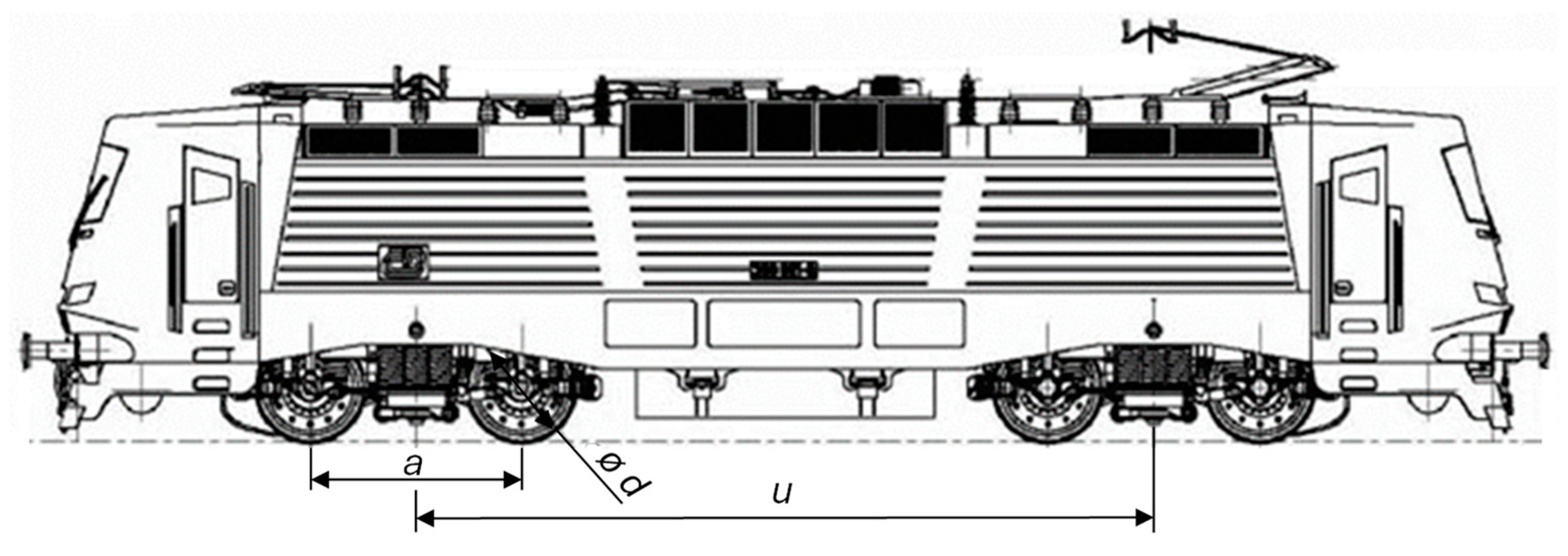
This paper deals with a modern universal four-axle electric locomotive (Figure 1). The wheelset drives are achieved by fully suspended traction blocks consisting of an asynchronous motor, a gearbox, and a hollow shaft. The primary suspension is achieved by sets of helical springs, the secondary suspension is flexicoil-type, and the wheelset guidance is achieved by connecting rods (see Figure 2, dark blue). The fundamental parameters of the vehicle are listed in Table 1. The stiffness values of the primary suspension and the wheelset guidance are related to one axle box, and the stiffness values of the secondary suspension to one side of the bogie.
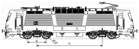
Figure 1.
Schematic plot of a four-axle locomotive.
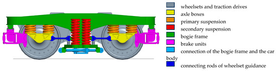
Figure 2.
Schematic plot of a bogie.

Table 1.
Numerical values of the fundamental parameters of the vehicle and its suspension.
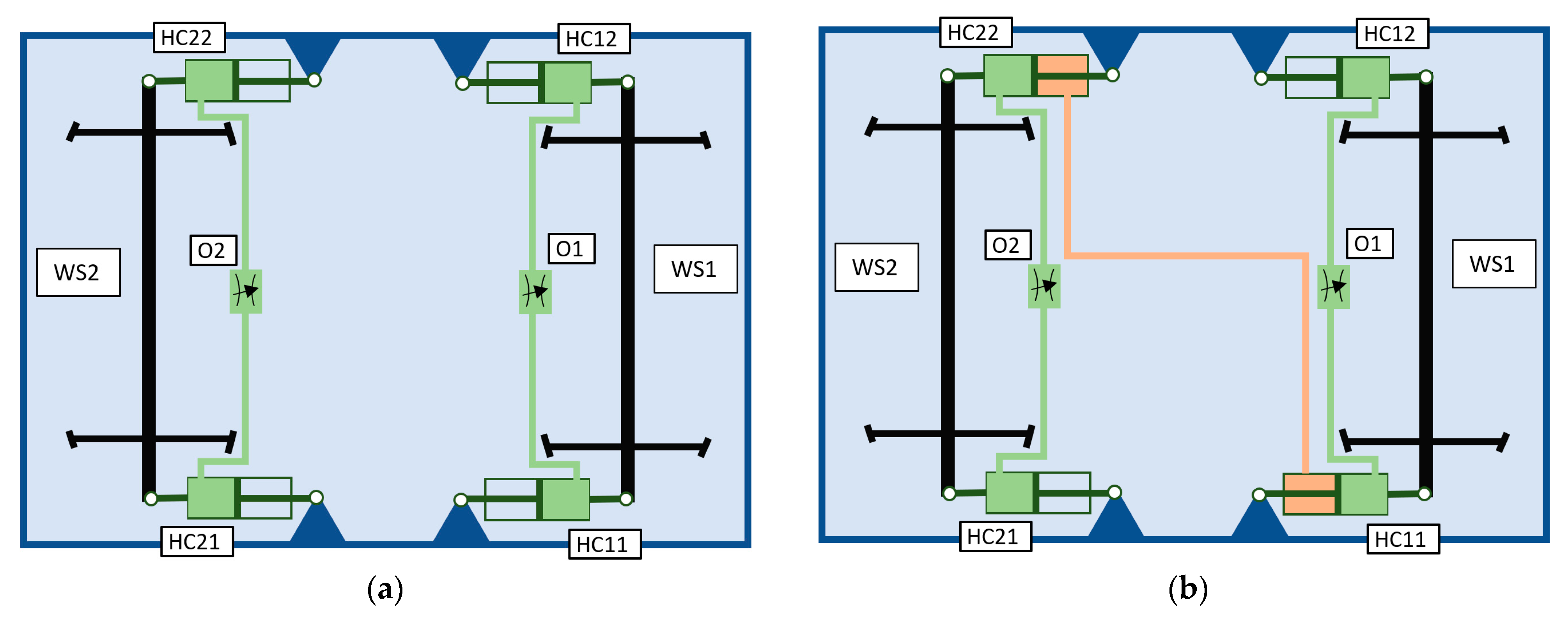
The principle of using hydraulic connections in wheelset guidance involves replacing steel rods with hydraulic cylinders and interconnecting them by pipelines. Two arrangements of connecting the hydraulic cylinders are evaluated in the paper: HWC1 (see Figure 3a) and HWC2 (see Figure 3b), where HC represents the hydraulic cylinders, O represents the nozzles, and WS represents the wheelsets. The first index indicates the wheelset number, while the second index denotes the side, where 1 corresponds to the right side and 2 to the left side.
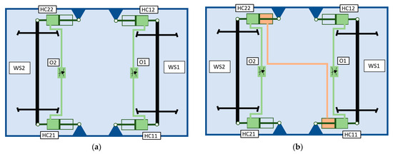
Figure 3.
Schematic plot of the bogie with hydraulic connection of the axle boxes (a) arrangement HWC1, (b) arrangement HWC2.
In the HWC1 scheme, the connection of the hydraulic cylinders ensures a stiff connection of the bogie and the wheelset centre, while the yaw stiffness of the wheelset guidance, i.e., the angular stiffness of the wheelset rotation around the vertical axis relative to the bogie frame, is minimized. The nozzles contain orifices O1 and O2 that limit the flow rate of the fluid between the hydraulic cylinders HC11 and HC12, as well as HC21 and HC22, and thus control the yaw rate of the wheelset. The hydraulic cylinder connections are independent for each wheelset.
The HWC2 scheme includes the same configuration as HWC1, but additionally introduces a crosslink between the wheelsets, achieved by interconnecting the chambers beneath the pistons of the hydraulic cylinders HC11 and HC22. It can be assumed that both configurations will exhibit similar characteristics in terms of vehicle behavior when negotiating curves. However, the cross-link between the wheelsets in HWC2 may contribute to a higher critical speed of the vehicle compared to the HWC1 arrangement.
The simulation model consists of the mechanical part model of the vehicle, which is created in Simpack 2021 Multibody software (MBS), see Figure 4, and the hydraulic system model created in the Simscape module of Matlab-Simulink R2019a software. Simscape is an extension of Matlab-Simulink, which specializes in the modelling and simulation of multi-domain physical systems. Both models are connected via the Simat interface that enables simultaneous simulation of Simpack and Simulink models. The two cosimulation models exchange their results with a time step of 0.0005 s using TCP/IP protocol.
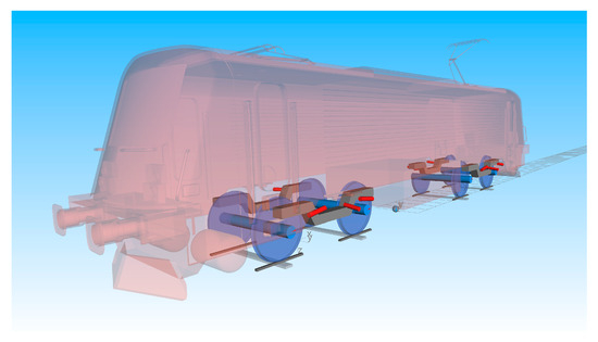
Figure 4.
Graphical representation of the mechanical part model of a vehicle.
The mechanical part represents a simplified model of an electrical locomotive. It consists of 7 rigid bodies (one car body, two bogie frames, four wheelsets) that are connected by linear force elements. The model of wheel–rail contacts respects nonlinear characteristics of the wheel and the rail profiles and calculates forces acting in the wheel–rail contacts using the FASTSIM method. The wheel profile is S1002, whereas the rail profile is 60E1. The model of the mechanical part was validated based on the measurement data obtained during the testing for acceptance of the locomotive in standard arrangement.
The hydraulic system model consists of hydraulic cylinders and other hydraulic components and their connections by pipelines. It also includes a mechanical connection between the ends of the hydraulic cylinders and parts of the bogie. Hydraulic cylinders are modelled using simple single or double acting hydraulic cylinder blocks with a piston diameter of 80 mm, a piston rod diameter of 30 mm, and a stroke of 14 mm. Factors such as friction and leakage are assumed to be negligible, and the hard stops are assumed to be fully inelastic in the model of hydraulic cylinders. The nozzles are modelled using the variable area hydraulic orifice block. ISO VG 32 hydraulic oil with a relative amount of trapped air of 0.005 is used as a hydraulic fluid. The hydraulic pipelines are modelled as ideal pipelines; the friction along the pipe length, the fluid compressibility, the fluid inertia, and the pipeline elasticity are neglected in the model of pipelines. The simplifications in the hydraulic system model were made because of the simplicity of the simulation model, which focused on the principal behavior of the proposed hydraulic system. Considering that the leakage is zero for a properly functioning hydraulic cylinder [25], the effects connected to the flexibility of pipes can be significantly reduced by the appropriate mechanical dimensioning of the pipes and other components of the system and the mass of hydraulic fluid is negligible compared to the masses of connected wheel-sets and bogie frame, it can be assumed that effects connected to leakage, flexibility and inertia of fluid will not fundamentally influence the obtained results.
3. Simulation Results
The goal of this study is to evaluate the contribution of hydraulic connections in the HWC1 and HWC2 arrangements to the natural radial alignment of the wheelsets in curves and thus to reduce wear. Furthermore, the study aims to determine the diameters of the O1 and O2 orifices to maximise the benefits of the wear reduction and show the impact on the critical speed.
3.1. High-Speed Stability
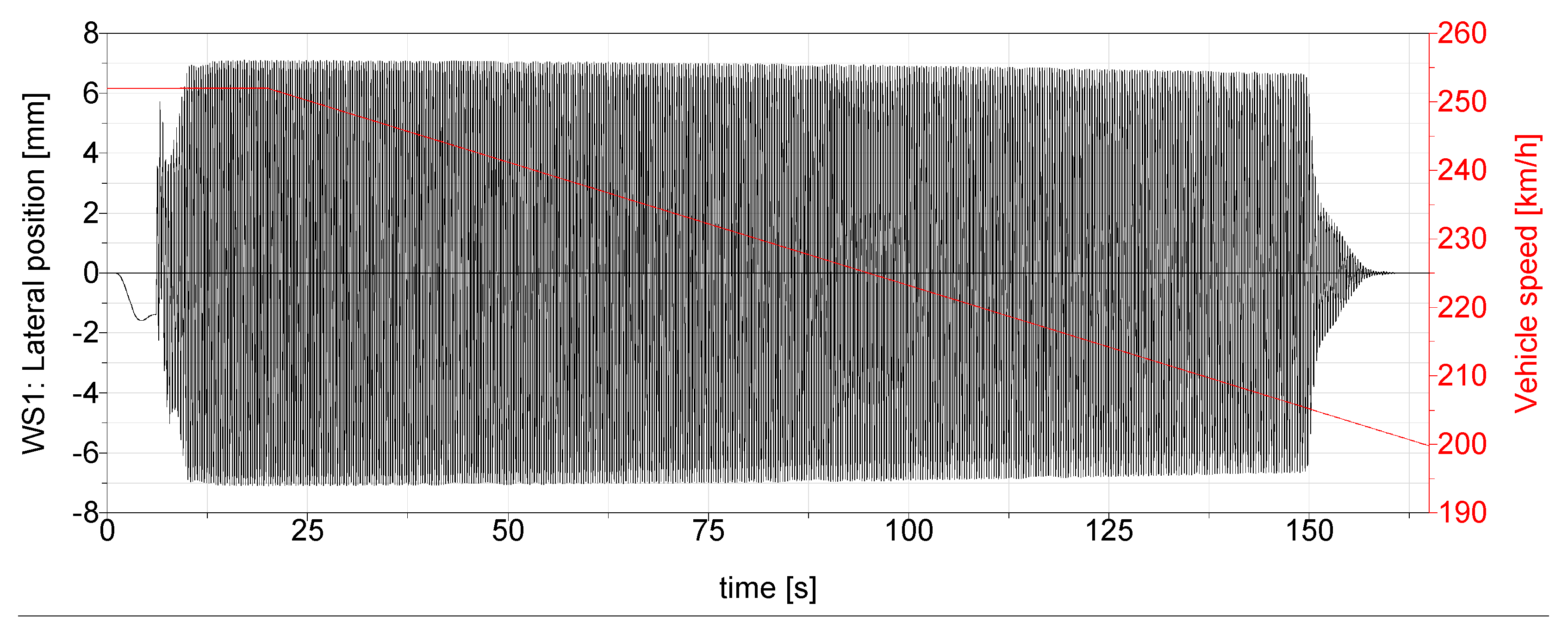
The critical speed was calculated using the method of path following of a hunting motion [26]. In this case, the high speed at which the vehicle moves in a limit cycle is used as the initial condition, and a continuous speed reduction is applied. The speed at which the lateral oscillations of wheelsets disappear is designated as the critical speed [27]. The simulations were carried out on an ideal track without irregularities with nominal parameters of gauge 1435 mm, rail inclination 1/40, and rail profile 60E1, considering the coefficient of friction in a wheel–rail contact of 0.4. The initial vehicle speed was set to 252 km/h. At the beginning of the simulation, a hunting motion of wheelsets was initiated by applying a 100 kN lateral force acting on the car body at time of 1 s to 6 s. From the time of 20 s, the vehicle speed was uniformly reduced with a deceleration of 0.1 km/h per second. The time development of the lateral position of the first wheelset was observed. The critical speed was evaluated as the vehicle speed at which the lateral oscillations of the wheelset disappear. The simulation results for the standard configuration locomotive with the wheelset guidance realized by stiff connecting rods (STD) are shown in Figure 5. Using this procedure, the critical speed of the STD locomotive was obtained at 202.4 km/h.
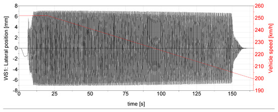
Figure 5.
Simulation results to determine the critical speed of the STD locomotive.
The application of a hydraulic system in a wheelset guidance will reduce the yaw stiffness of a wheelset and bogie frame connection, and thus facilitate natural radial steering of a wheelset in track curves. On the other hand, this reduction in yaw stiffness can be expected to cause a significant decrease in the critical speed of the vehicle. Therefore, nozzles containing orifices O1, O2 (see Figure 3) are placed in the connection of the hydraulic cylinders, which limit the flow of the hydraulic fluid and thus limit the speed of the yaw motion of the wheelsets, especially at higher frequencies. Orifices are commonly used for throttling and controlling oil flows in all hydraulic applications, and they are supplied by most manufacturers’ hydraulic components. They are produced with holes of calibrated diameters ranging from 0.2 mm to several millimeters. Close tolerances of an orifice hole diameter guarantee high flow accuracy. The goal is to find an appropriate size of an orifice that is small enough to ensure a necessary damping for a sufficiently high critical speed, and at the same time, it is large enough to allow necessary flow for a sufficiently fast adaptation of the wheelset position in a track curve.
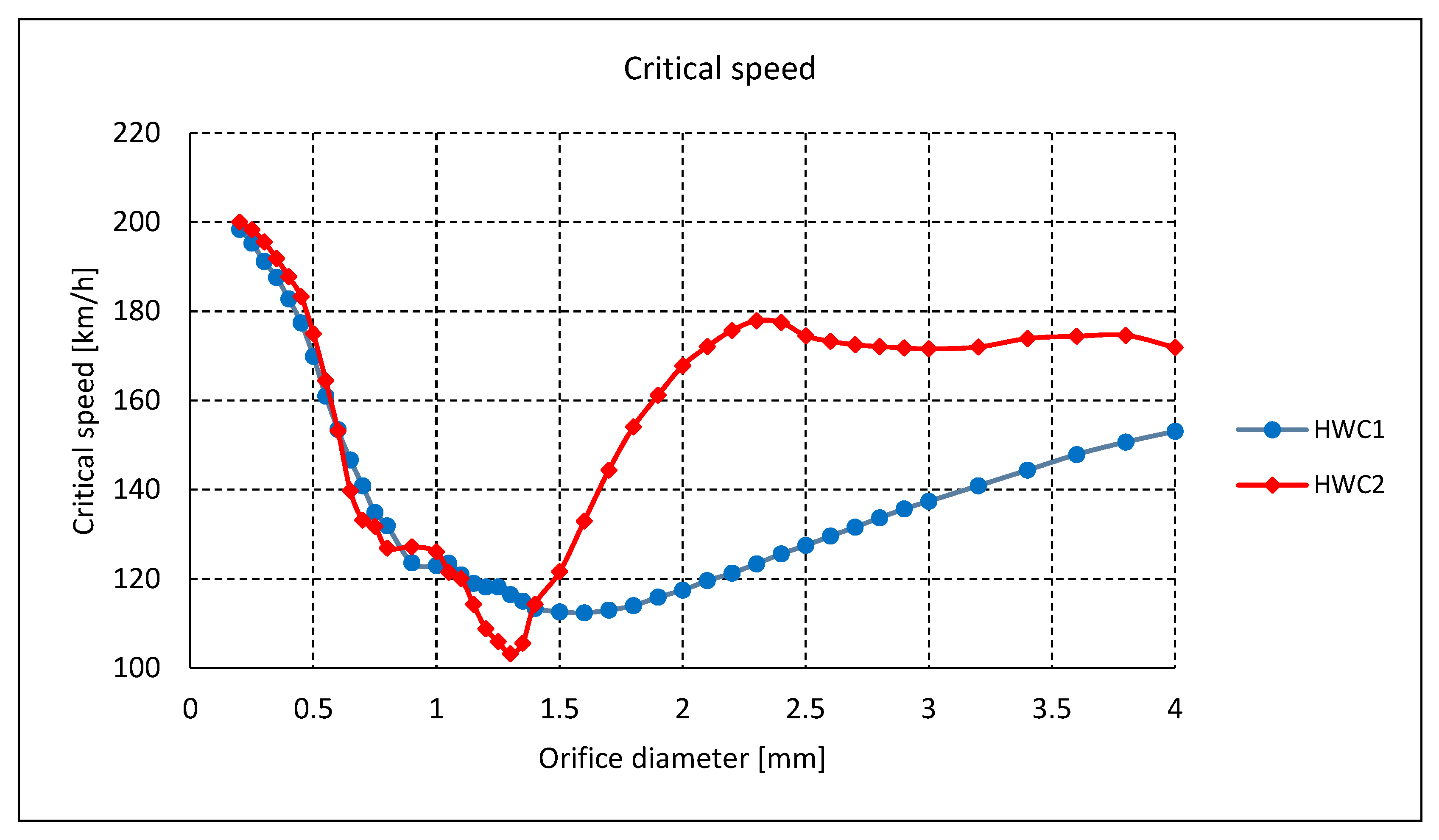
Therefore, simulations were performed to determine the critical speed for the HWC1 and HWC2 arrangements for orifice diameters in the range of 0.2 to 4 mm. The results are shown in Figure 6. Apart from the arrangement of the wheelset guidance system, all simulation conditions were the same as for the STD locomotive.
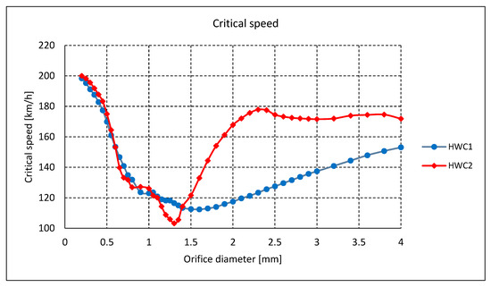
Figure 6.
Critical speed of the HWC1 and HWC2 arrangements.
Calculations of the critical speed of the locomotive in arrangements HWC1 and HWC2 confirmed the expected decrease in the critical speed compared to the STD locomotive. At the beginning, the critical speed decreases with increasing orifice diameter. The minimum critical speed is reached for orifice diameters of 1.6 mm for HWC1 and 1.3 mm for HWC2. With further increase in the orifice diameter, the critical speed increases again but does not reach the initial values. The expectation that the linkage of both wheelsets of the bogie in HWC2 contributes to a higher critical speed compared to the HWC1 was confirmed; however, it is not in the full range of orifice diameters. For the range of small orifice diameters up to 0.6 mm, the critical speed of HWC2 is higher than the critical speed of HWC1. However, the difference between the arrangements is less than 5 km/h. On the other hand, in the range of diameters from 1.2 to 1.4 mm, the critical speed of HWC2 is lower compared to HWC1. The main difference can be seen for the orifice diameters larger than 1.6 mm, where the critical speed of HWC2 is higher than that of HWC1.
3.2. Curving Behavior
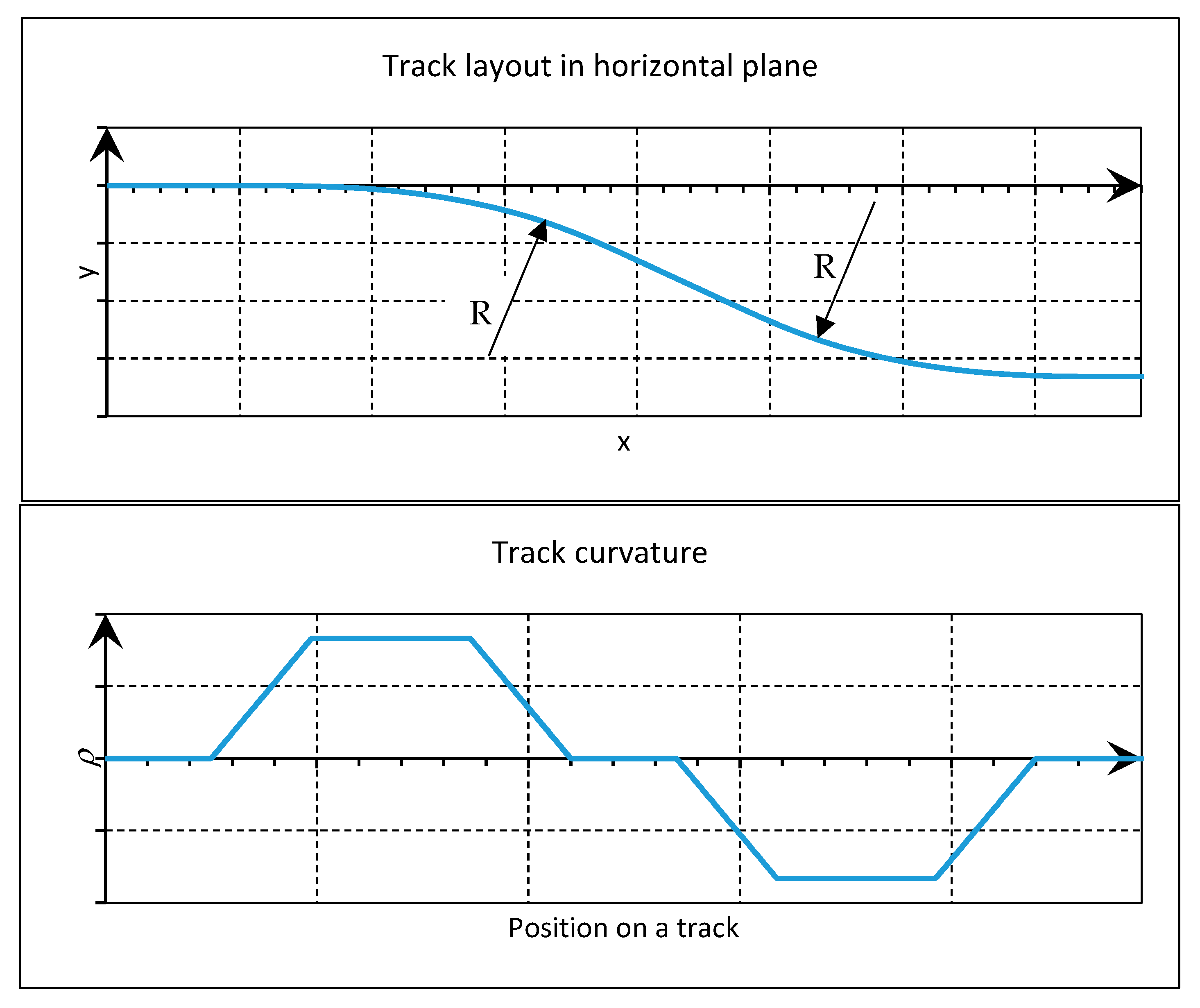
To assess the benefit of the hydraulic system in a wheelset guidance on the behavior of the vehicle in a curved track, simulations of a running through a track curve were performed for various curve radii R, various cant deficiencies I, and therefore various running speeds v, and various diameters od of orifices O1 and O2. The track radii were chosen to comprise a wide range of railway line track curve radii, from small radius curves to large radius curves. Each radius was negotiated at three speeds corresponding to a rail cant deficiency I of 150, 0, and −100 mm. The rail cant D was 150 mm in all radii. The test track consisted of two opposing curves connected by a 100 m long straight section. The lengths of the transition sections Lt, i.e., the track sections of the track where the curvature changes, were determined as short as possible with regard to the construction parameters of the railway tracks specified in the appropriate EN standards. The shape of the track is shown in Figure 7.
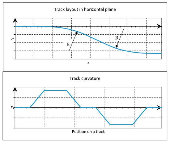
Figure 7.
Shape of the test track.
Finally, for the curve behavior assessment, 21 simulation scenarios were defined, the parameters of which are summarized in Table 2.
Table 2.
Simulation parameters for curving behavior assessment.
The run of the locomotive according to scenarios 1 to 21 was simulated for the STD locomotive and for the hydraulic connection configurations HWC1 and HWC2 with orifice diameters of <0.2, 0.25, 0.3, 0.35, 0.4, 0.5, 0.6, 0.7, 0.8, 0.9, 1> mm. The simulations were performed for the nominal shape of the wheel and rail profiles and the friction coefficient in the wheel–rail contacts f = 0.4. A total of 484 simulations were performed, and the time development of the wear number Tγ [28,29] on all individual wheels was calculated.
The wear number is defined as follows:
where and is a longitudinal, respectively a lateral force in a wheel rail contact, and are longitudinal and lateral creepages, is a spin torque and denotes a spin.
The frictional power in a wheel–rail contact is calculated by multiplying the wear number with a creep reference velocity, which is the speed of the vehicle v:
Finally, the frictional work, i.e., the dissipated energy in the wheel–rail contact, is obtained by integrating the frictional power over time:
where is the start, respectively, the end time.
The amount of material removed in the contact of two bodies can be expressed by several damage models [30,31]. The correlation between the wear number Tγ and the amount of material removed was studied in [32], obtaining the correlation value 0.96 between wear number Tγ and the wear depth, and 0.79 between the wear number and the wear area on the outer wheel. One of the often-used damage models is the energetic law proposed by Krause and Poll [33]. According to this theory, the total volume of removed material ΔV is proportional to the work of the friction forces Wfrict, with a proportionality constant depending on the wear regime:
where A is the wheel–rail contact patch area; Cm and Cs are the proportionality coefficients for the mild and severe regimes, respectively. The wear regime depends on the specific frictional power in the contact patch.
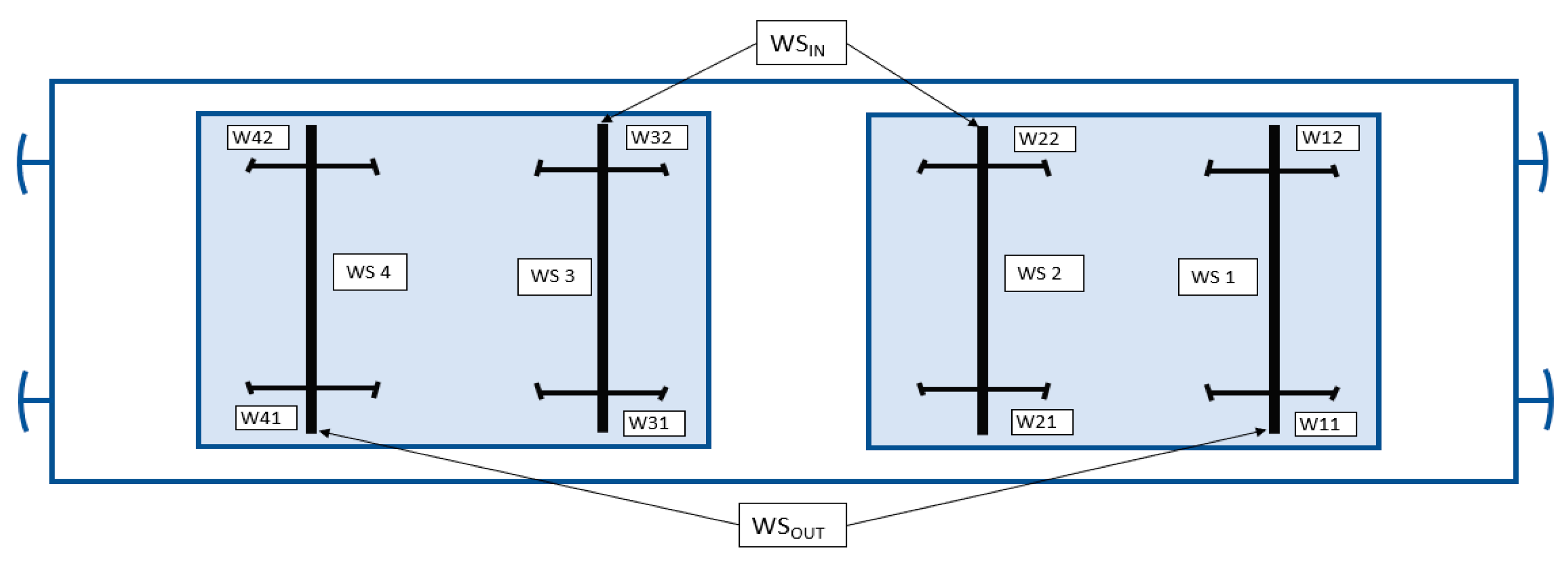
Based on the assumption that the damage of wheel and rail surfaces in track curves is primarily caused by wear, i.e., an abrasion of the two sliding surfaces, and the amount of wear is proportional to the frictional work is the , which is used as a wear criterion in this study. In practice, a locomotive is operated both in the forward and the backward direction. When in the backward direction of travel, the wheelset 1 becomes the wheelset 4 and the wheelset 2 becomes the wheelset 3. With the assumption of an even distribution of the forward and reverse travel and an even distribution of the right and left curves, the wear of all wheels of the first and fourth wheelsets and all wheels of the second and third wheelsets will be the same. Wheelsets 1 and 4 will be denoted as outer wheelsets (OUT index) and wheelsets 2 and 3 as inner wheelsets (IN index); see Figure 8. Therefore, the results of the simulations were averaged according to the following relationships:
where is the resultant frictional work on the wheels of the outer wheelsets, is the resultant frictional work on the wheels of the inner wheelsets. denote the frictional work on individual wheels. Index i corresponds to the number of wheelsets, and index j represents the side of a wheel, 1 for the right side, 2 for the left side.
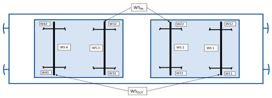
Figure 8.
Designations of wheelset and wheels.
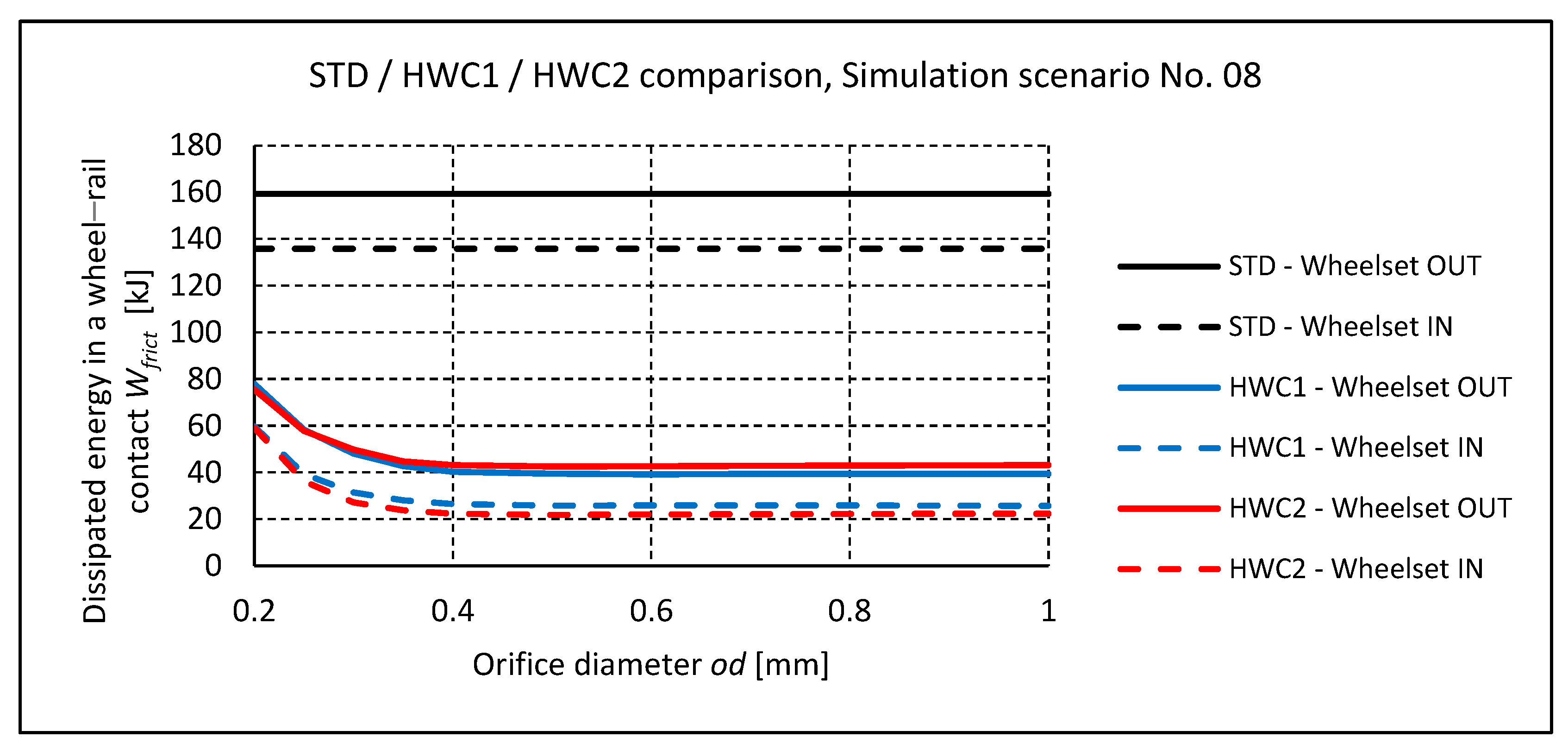
Figure 9 shows the results for the simulation scenario No. 08, that is, the run in the radius of the track of 250 m with the cant deficiency of 150 mm, as an example of the obtained results. Analogical courses were obtained for all assessed simulation scenarios.
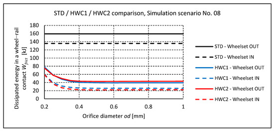
Figure 9.
Simulation scenario No. 08. Frictional work in wheel rail contacts.
The results of the simulations show that the application of hydraulic connections leads to a significant reduction of frictional work in the wheel–rail contacts. The HWC1 and HWC2 connections are practically equivalent. The HWC1 arrangement achieves slightly better results, especially on outer wheelsets. The amount of reduction in frictional work depends on the diameter of the orifice od. For very small orifice diameters, when the position of the wheelset cannot change quickly enough to adapt to the change in the track curvature due to a significant flow throttling, this benefit is lower. As the orifice diameter increases, the frictional work decreases. The average values of the reduction in the magnitude of frictional work across all simulation scenarios are given in Table 3.
Table 3.
Average reduction in frictional work compared to a standard locomotive across simulation scenarios 01–21.
The figures in Table 3 show that for the orifice diameter od > 0.35 mm, a further reduction of the frictional work is very low or remains constant. For the orifice diameter od > 0.7 mm, an increase in the frictional work can be observed. This can be attributed to the decrease in the stability of the vehicle and more pronounced lateral oscillations of wheelsets, especially in the transition sections of large radius curves. In contrast, the critical speed decreases steadily in the range of od from 0.2 to 0.8 mm (see Figure 6). The requirement for high critical speed and low wear is therefore contradictory, and a compromise between a high critical speed and the amount of wear reduction must be made. However, increasing the orifice diameter above od = 0.35 mm brings negligible benefits in terms of wear, but leads to a significant decrease in the critical speed. On the other hand, a choice of od < 0.35 mm leads to a higher critical speed, but at the cost of a decrease in the benefit of the reduction in wear. This applies to both arrangements.
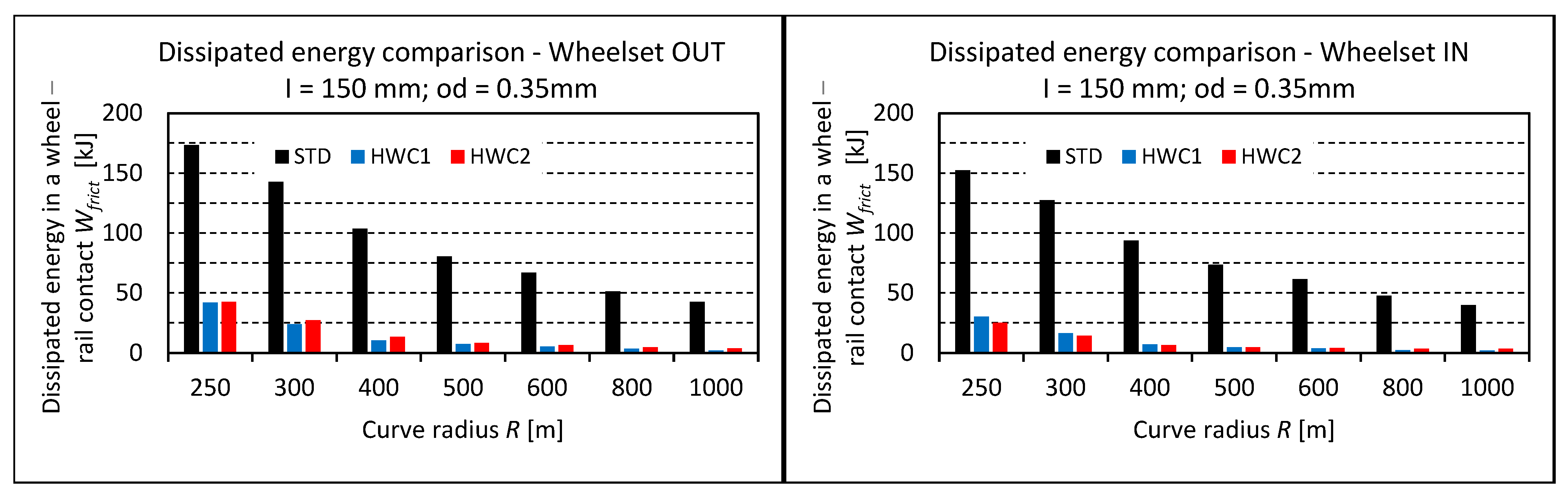
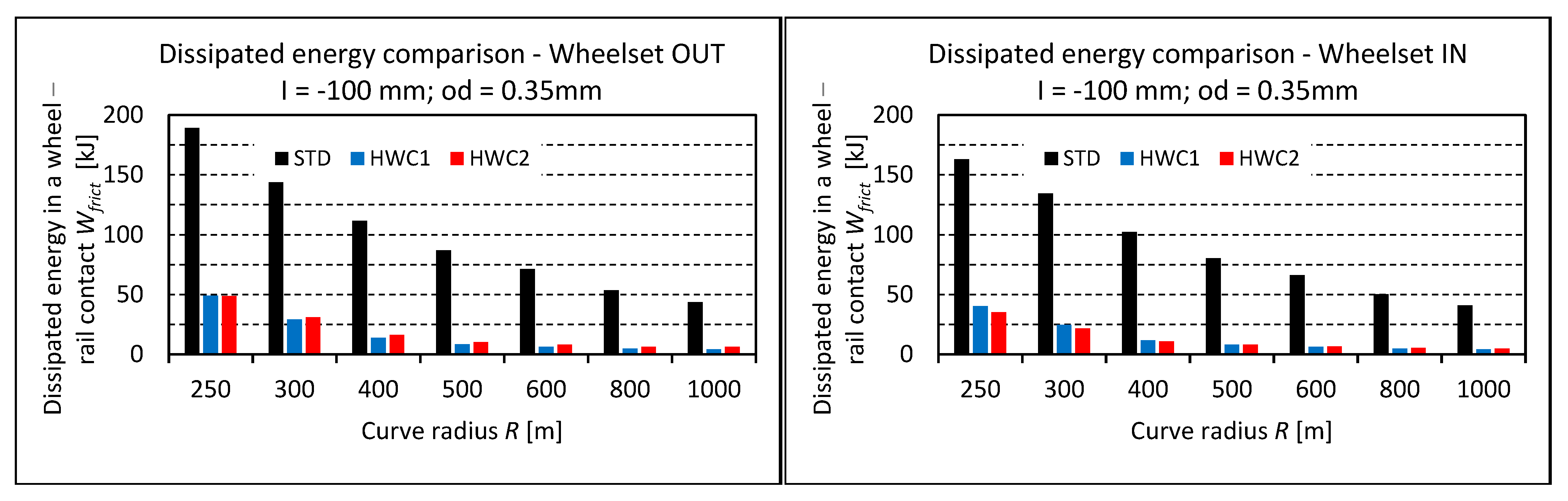
Since the main objective of the presented work is to show the potential benefit of the proposed hydraulic system in terms of wear, an orifice diameter od = 0.35 mm was chosen for further simulations. For this orifice diameter, Figure 10, Figure 11 and Figure 12 show a comparison of the frictional work on the outer and inner wheelsets with the STD locomotive. The numerical values are provided in Table 4. The results obtained show that the application of hydraulic connections in a wheelset guidance significantly reduces the amount of frictional work in the wheel–rail contacts on all wheelsets. This applies to all evaluated simulation scenarios, i.e., across a wide range of track-curve radii and rail superelevation deficiencies.
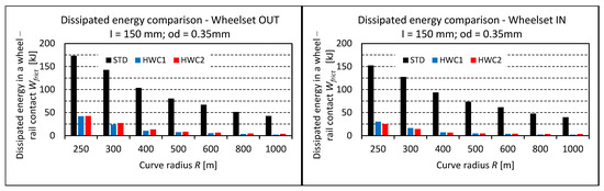
Figure 10.
Frictional work in wheel–rail contacts for the cant deficiency I = 150 mm.
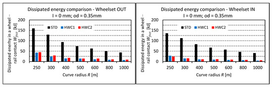
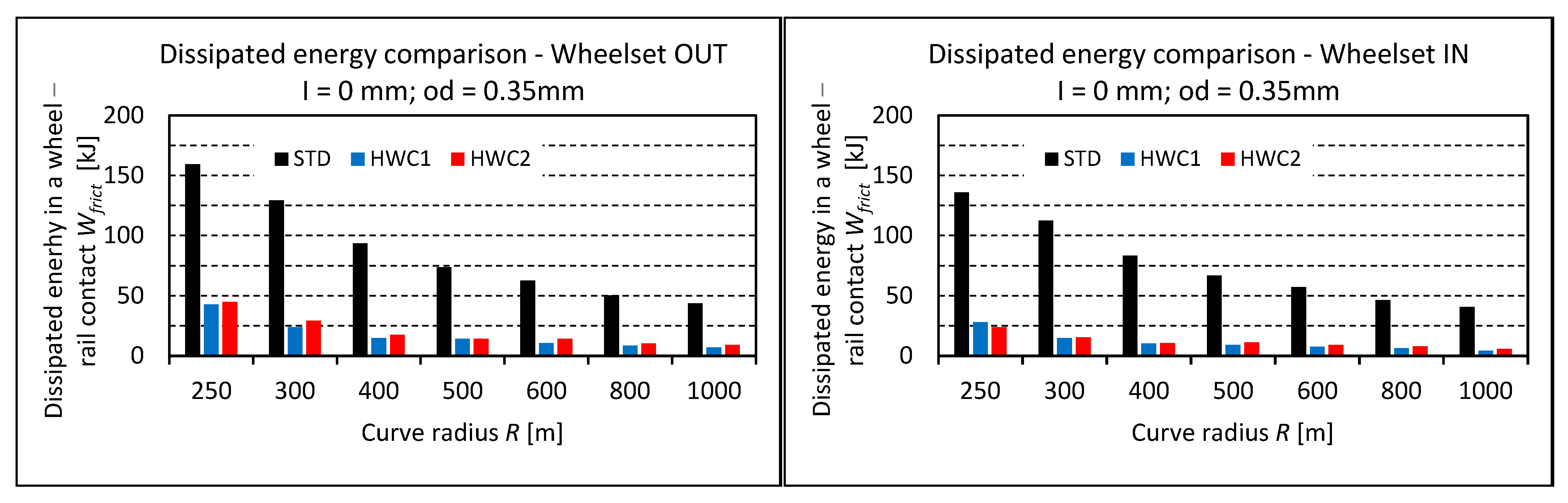
Figure 11.
Frictional work in wheel–rail contacts for the cant deficiency I = 0 mm.
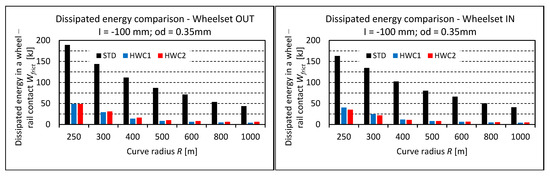
Figure 12.
Frictional work in wheel–rail contacts for the cant deficiency I = −100 mm.
Table 4.
Curving behavior: comparison of the frictional work, od = 0.35 mm.
The reduction for the HWC1 vehicle arrangement ranges from 73 to 95% for the outer wheelsets and from 79 to 96% for the inner wheelsets. For the HWC2 arrangement, the reduction in the frictional work for the outer wheelsets is from 72 to 91% and for the inner wheelsets, 82 to 94%. The results for both configurations are practically equivalent. In small-radius track curves, HWC1 achieves slightly better results on the outer wheelsets, whereas HWC2 achieves slightly better results on inner wheelsets, but the differences are very small.
3.3. Running in a Real Track
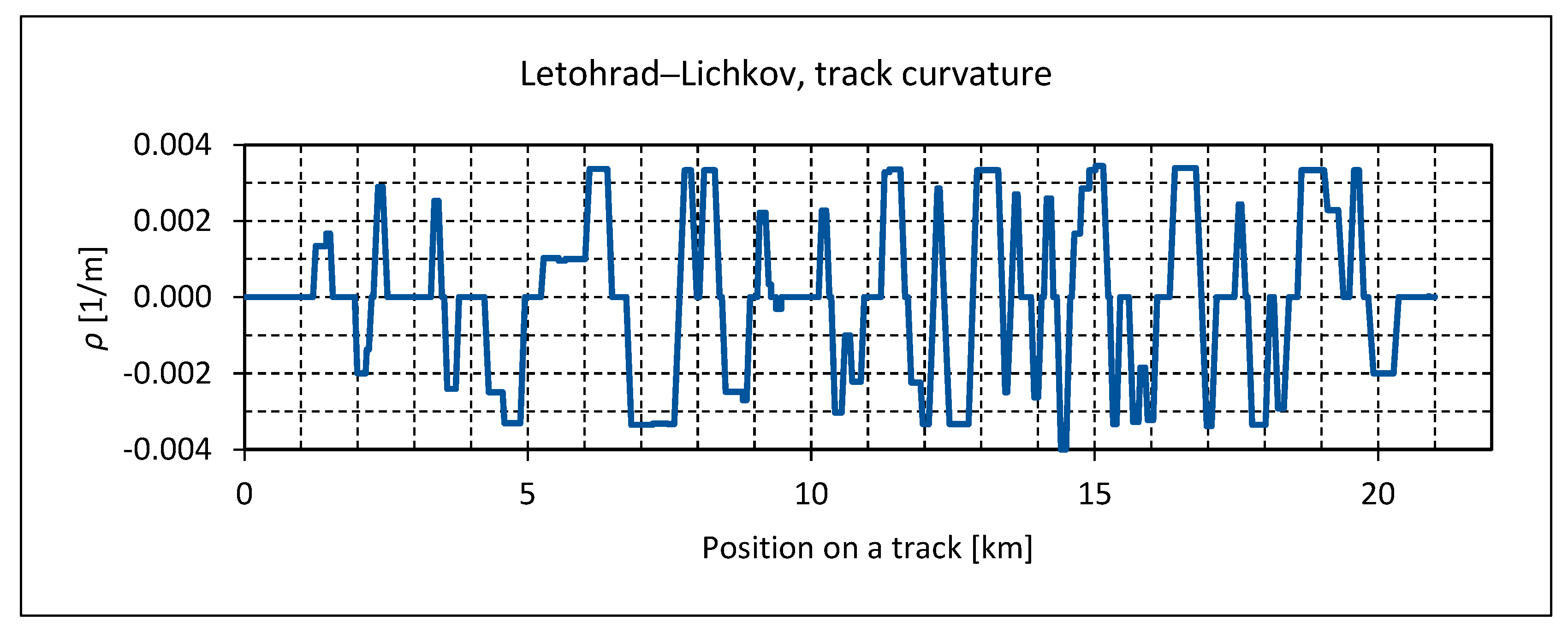
The simulations described in the previous sections were performed under the assumption of an ideal track geometry, with no track irregularities considered. To assess the vehicle’s behavior under real-world conditions, a simulation for a 20 km section of the Letohrad–Lichkov railway line was performed. This is a highly curved track in eastern Bohemia, featuring numerous curves with a radius of 300 m, and occasionally as small as 250 m. Figure 13 illustrates the profile of the track curvature .
where R represents the radius of the curve. Positive curvature values correspond to right-hand curves, while negative values indicate left-hand curves.
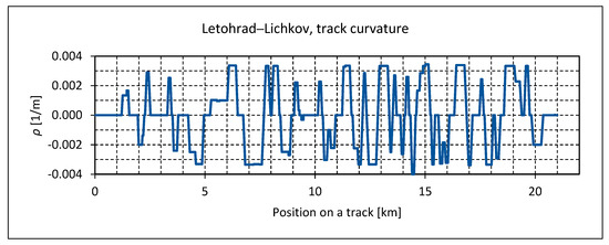
Figure 13.
Track section Letohrad–Lichkov, the track curvature.
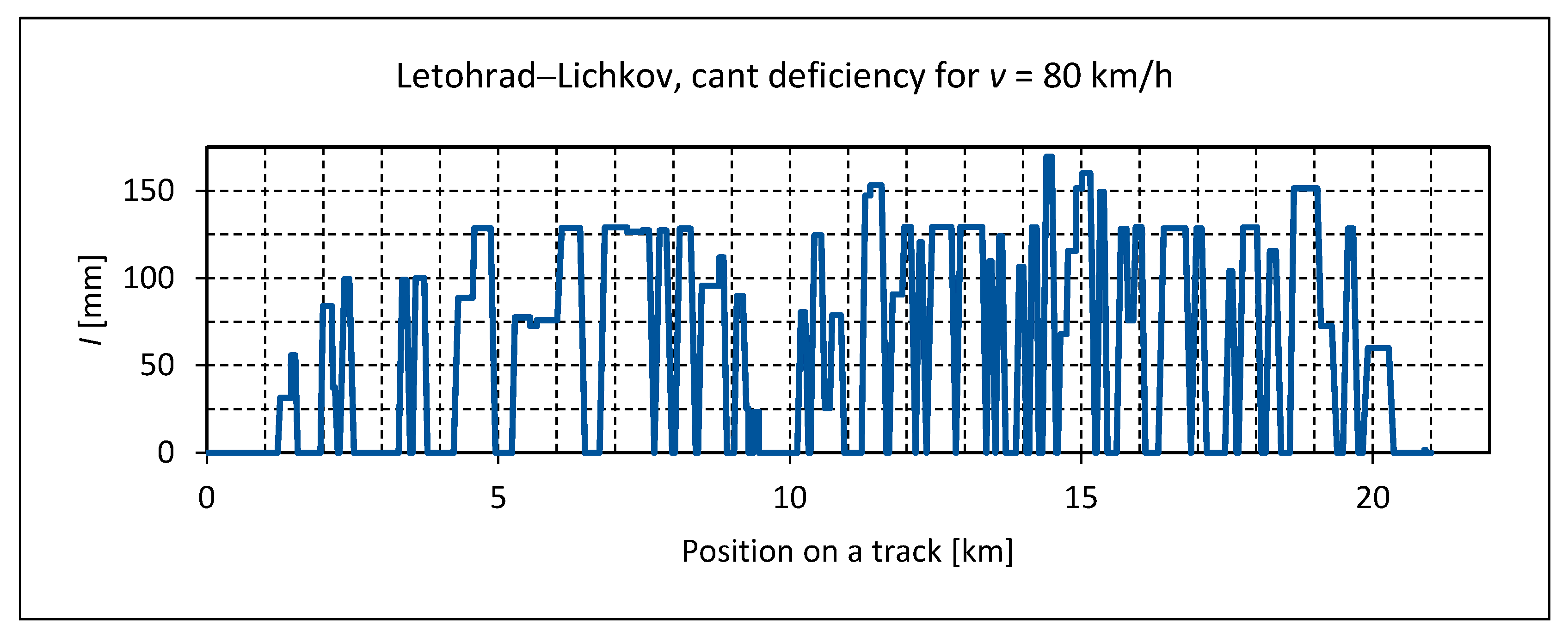
The simulation was carried out at a constant speed of 80 km/h, which corresponds to the cant deficiency values of around 130 mm in the majority of the curves. In some isolated cases, the cant deficiency reaches values of 150 mm, and in exceptional cases, 170 mm, as shown in Figure 14.
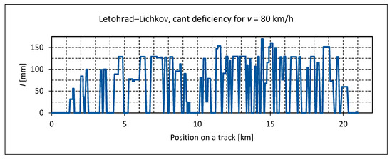
Figure 14.
Track section Letohrad–Lichkov: the cant deficiency for vehicle speed 80 km/h.
The simulations were carried out for four levels of track irregularities: ‘no’, ideal track without irregularities, ‘low’, low level of irregularities, ‘high’, high level of track irregularities, and ‘meas’, track irregularities obtained by a track geometry measurement. The track irregularities ‘low’ and ‘high’ show the range of the track maintenance state. They are modelled as a pseudo-stochastic signal composed of 1000 harmonic functions in the range of wavelengths from 3 to 25 m. The irregularities were on the basis of the spectral power densities of the measured irregularities of the railway track published in the ERRI report B176 [34].
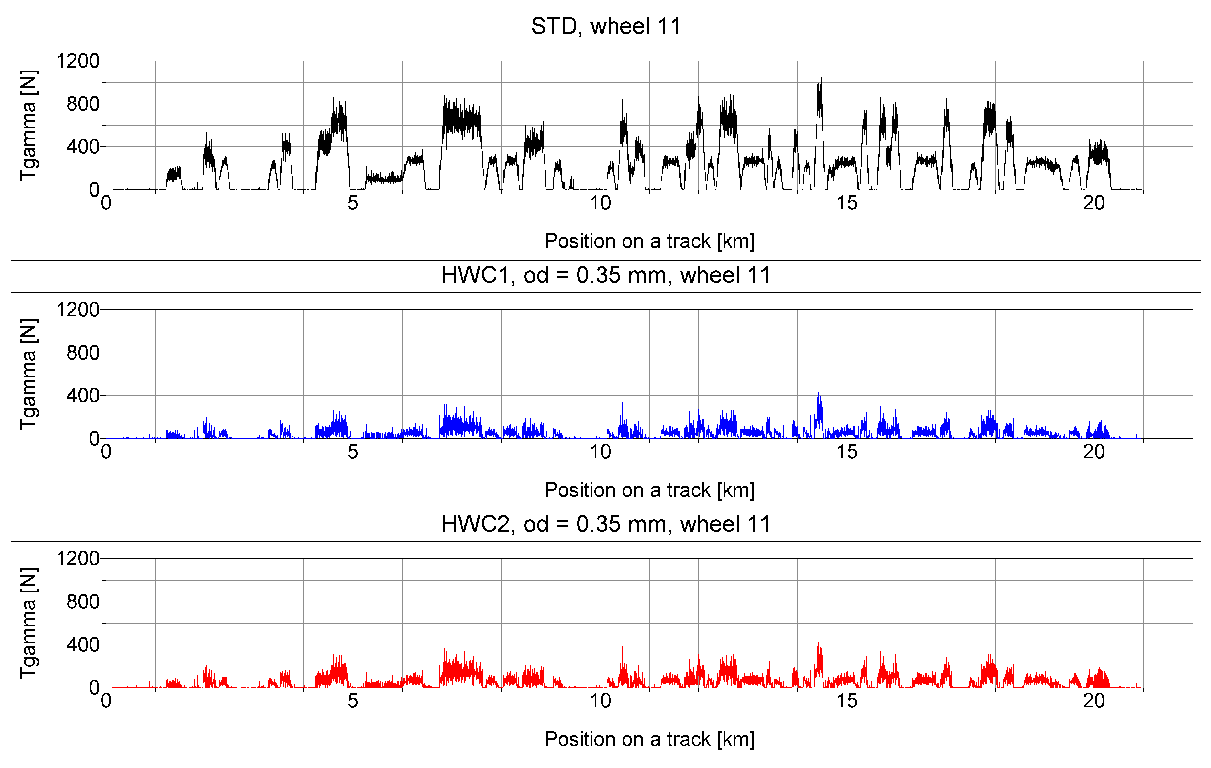
The simulations were carried out for the STD vehicle arrangement and the HWC1 and HWC2 configurations, using the orifice diameter of 0.35 mm. The coefficient of friction in the wheel–rail contact was set to f = 0.4, corresponding to dry conditions.
The wear number values on all wheels were observed in the simulation. An example of the obtained results, the values on wheel 11, is shown in Figure 15. It can be seen that the wear number values for the HWC1 and HWC2 configurations are significantly lower than for the STD locomotive, especially in tight curves.
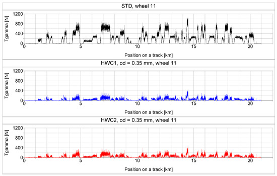
Figure 15.
Track section Letohrad–Lichkov: low level of track irregularities, wear number values on wheel 11.
The total frictional work on the inner and outer wheelsets of the vehicle was then calculated from the wear number time courses using Equations (1)–(4). The obtained values are summarized in Table 5.
Table 5.
Run on the track Letohrad–Lichkov: the comparison of the frictional work, od = 0.35 mm.
Simulations of running on the real track have shown that the application of the hydraulic system in wheelset guidance is capable of providing a significant reduction in the frictional work at the wheel–rail contacts, ranging from 70 to 90%. The benefit of the hydraulic system decreases slightly due to track irregularities; however, even on tracks with a high level of irregularities, both the HWC1 and HWC2 systems provide a reduction in frictional work in the range of 70 to 80%. The results for both systems are practically identical on the inner wheelsets, while on the outer wheelsets, the HWC1 configuration reaches slightly better results.
All the simulations described above were carried out under the assumption of a friction coefficient in the wheel–rail contact of f = 0.4, corresponding to very good adhesion conditions on a clean and dry rail. Under deteriorated adhesion conditions, the friction coefficient can decrease significantly due to moisture and contaminants [35]. To assess the behavior of the system under such conditions, simulations of running on the Letohrad–Lichkov track with a low level of friction coefficient f = 0.15 were conducted; the results are summarized in Table 6.
Table 6.
Run on the track Letohrad–Lichkov: the comparison of the frictional work at deteriorated adhesion conditions f = 0.15.
Simulations under deteriorated adhesion conditions showed a reduction in the frictional work of both hydraulic systems compared to the standard locomotive. Similar to good adhesion conditions, the benefit of the hydraulic wheelset guidance system slightly decreases with increasing level of track irregularities. The relative benefit of the hydraulic wheelset guidance is lower under deteriorated adhesion conditions compared to a dry rail. The reduction in frictional work in the wheel–rail contacts ranges from 40 to 46% for HWC1 and 41 to 46% for HWC2. HWC2 performed slightly better than HWC1, whereas under good adhesion conditions, the opposite is true. This can be attributed to the fact that at low friction conditions, the angle of attack of wheelset 1 is higher than at good friction conditions. This is due to the equilibrium position of the wheelset given by forces acting in the primary suspension, the wheelset guidance, and the wheel–rail contact forces being limited by low friction. This effect is more pronounced in HWC1, because in HWC2, the position of wheelset 1 is also assisted by the cross-linking to wheelset 2.
4. Conclusions
A hydraulic system based on the replacement of the rigid rods of the wheelset guidance with hydraulic cylinders and their interconnection was proposed. This system was designed in two arrangements, HWC1 and HWC2, which differ in the way the hydraulic cylinders are connected. The computer simulations were focused on comparing the frictional work in the wheel–rail contacts of a standard locomotive and a locomotive equipped with the hydraulic wheelset guidance system and the assessment of the effect of the proposed hydraulic system on the reduction of the critical speed. Based on the simulation results, the following conclusions can be drawn:
- The critical speed of a vehicle equipped with the proposed hydraulic system is lower compared to a standard vehicle with otherwise identical parameters;
- The diameter of the orifice significantly influences the flow rate of the hydraulic fluid, affecting vehicle stability and critical speed;
- The expected advantage of the HWC2 arrangement in achieving a higher critical speed compared to the HWC1 arrangement was confirmed, particularly for larger orifice diameters (od > 2 mm). In the range of small orifice diameters (od = 0.2 to 1 mm), the critical speed of both arrangements is very similar;
- With an orifice diameter of od = 0.35 mm, the critical speed of the vehicle was 187.6 km/h for HWC1 and 191.9 km/h for HWC2. The critical speed of a standard vehicle with the same parameters was 202.4 km/h. Thus, the reduction in critical speed is 7.3% for HWC1 and 5.2% for HWC2;
- Simulations of passing through curves of different radii with minimal length of the transition sections showed that, for the applied hydraulic fluid and hydraulic cylinder sizes, an orifice diameter of od = 0.35 mm is sufficient for the timely adaptation of the wheelset position in the transition track sections;
- Simulations of running on a 20 km section of a real track with a number of curved sections demonstrated a significant benefit of both hydraulic systems in reducing frictional work in wheel–rail contacts, thereby decreasing wheel and rail wear. This reduction reaches 75–82% on the outer wheelsets and 79–87% on the inner wheelsets for HWC1 and 72–79% on the outer wheelsets and 79–87% on the inner wheelsets for HWC2. As the track irregularities increase, the benefit of the hydraulic system decreases, but even for a high level of irregularities, it does not drop below 70%;
- The benefit of the hydraulic wheelset guidance systems in reducing the frictional work at the wheel–rail contacts is relatively lower under deteriorated adhesion conditions compared to a dry rail. Nevertheless, there is still a significant improvement. The reduction in frictional work ranges from 41 to 48% for both arrangements of the hydraulic system.
Since the results of both proposed systems were very similar, the HWC1 arrangement can be recommended, as it is simpler and contains fewer parts and connections. A less than 10% reduction in the critical speed of the vehicle can be compensated for by appropriately tuning the elastic and damping elements of the suspension. Tuning the characteristics of the yaw dampers [36] or the utilisation of innovative design of yaw dampers [37] could be recommended as the first step, as these devices influence significantly the critical speed, but does not affect the angular stiffness of the wheelset and bogie frame connection and thus the ability of the wheelset to adapt to the track curvature. Given that the main benefit of the proposed system occurs in curves with very small radii, which are always passed at low speeds, the reduction in critical speed can also be eliminated by locking the hydraulic system at higher speeds. Alternatively, it is possible to equip the system with a variable diameter and control the flow throttling depending on the vehicle speed, but at the cost of complicating the entire system.
It is possible to conclude that the simulations performed confirmed the significant potential benefit of the proposed system in reducing wheel wear on curved tracks, and it deserves further investigation. For the following work, it would be advisable to evaluate several additional aspects that were not considered in the simulations, such as changes in system properties due to temperature variations and a detailed assessment of effects related to the flexibility of hydraulic system components and the compressibility of the hydraulic fluid. Moreover, before an eventual practical implementation, many additional tasks, like addressing the failure modes and maintenance procedures, have to be solved to ensure long-term functionality and reliability of the proposed system.
Funding
This research has been realized using the support of the Technological Agency, Czech Republic, programme National Competence Centres, Project No TN02000054 “Božek Vehicle Engineering National Center of Competence” and Project No TN01000026 “Josef Božek National Centre of Competence for Surface Vehicles”.
Data Availability Statement
The raw data supporting the conclusions of this article will be made available by the authors on request.
Conflicts of Interest
The author declares no conflicts of interest.
References
- Andersson, E.; Stichel, S.; Orvnäs, A.; Persson, R. How to Find a Compromise between Track Friendliness and the Ability to Run at High Speed. In Proceedings of the First International Conference on Railway Technology: Research, Development and Maintenance; Civil-Comp Press: Stirlingshire, Scotland, 2012; p. 68. [Google Scholar]
- Ye, Y.; Sun, Y.; Dongfang, S.; Shi, D.; Hecht, M. Optimizing wheel profiles and suspensions for railway vehicles operating on specific lines to reduce wheel wear: A case study. Multibody Syst. Dyn. 2021, 51, 91–122. [Google Scholar] [CrossRef]
- Polach, O. Curving and Stability Optimisation of Locomotive Bogies using Interconnected wheelsets. Veh. Syst. Dyn. 2004, 41, 53–62. [Google Scholar]
- Zhang, Z.; Zhou, J.; Sun, W.; Thompson, D.; Shen, G.; Gong, D.; Wang, Z.; Wang, T.; Li, X. Analytical study and evaluation of self-steering ability of elastically constrained wheelsets under traction/braking conditions. Veh. Syst. Dyn. 2024, 63, 333–350. [Google Scholar] [CrossRef]
- Carballeira, J.; Baeza, L.; Rovira, A.; García, E. Technical characteristics and dynamic modelling of Talgo trains. Veh. Syst. Dyn. 2008, 46, 301–316. [Google Scholar] [CrossRef]
- Shimokawa, Y.; Mizuno, M. Development of the New Concept Steering Bogie. Nippon. Steel Sumitomo Met. Tech. Rep. 2013, 41–47. [Google Scholar]
- Hecht, M. Wear and energy-saving freight bogie designs with rubber primary springs: Principles and experiences. Proc. Inst. Mech. Eng. Part F J. Rail Rapid Transit 2009, 223, 105–110. [Google Scholar] [CrossRef]
- Megna, G.; Bracciali, A. Gearless Track-Friendly Metro with Guided Independently Rotating Wheels. Urban Rail Transit 2021, 7, 285–300. [Google Scholar] [CrossRef]
- Fu, B.; Giossi, R.; Persson, R.; Stichel, S.; Bruni, S.; Goodall, R. Active suspension in railway vehicles: A literature survey. Railw. Eng. Sci. 2020, 28, 3–35. [Google Scholar] [CrossRef]
- Farhat, N.; Ward, C.; Goodall, R.; Dixon, R. The benefits of mechatronically-guided railway vehicles: A multi-body physics simulation study. Mechatronics 2018, 51, 115–126. [Google Scholar] [CrossRef]
- Persson, R.; Goodall, R.; Sasaki, K. Carbody tilting—Technologies and benefits. Veh. Syst. Dyn. 2009, 47, 949–981. [Google Scholar] [CrossRef]
- Persson, R. Tilting Trains: Benefits and Motion Sickness. Proc. Inst. Mech. Eng. Part F J. Rail Rapid Transit 2010, 224, 513–522. [Google Scholar] [CrossRef]
- Park, J.; Yang, H. Design of a lateral active suspension controller for railway vehicles: A focus on ride comfort and perturbations. J. Mech. Sci. Technol. 2023, 37, 5781–5788. [Google Scholar] [CrossRef]
- Park, J.; Shin, Y.; Hur, H.; You, W. A practical approach to active lateral suspension for railway vehicles. Meas. Control 2019, 52, 1195–1209. [Google Scholar] [CrossRef]
- Mei, T.; Goodall, R. Recent Development in Active Steering of Railway Vehicles. Veh. Syst. Dyn. 2003, 39, 415–436. [Google Scholar] [CrossRef]
- Perez, J.; Goodall, R. Control strategies for active steering of bogie-based railway vehicles. Control Eng. Pract. 2002, 10, 1005–1012. [Google Scholar] [CrossRef]
- Hur, H.; Shin, Y.; Ahn, D. Analysis on Steering Performance of Active Steering Bogie According to Steering Angle Control on Curved Section. Appl. Sci. 2020, 10, 4407. [Google Scholar] [CrossRef]
- Giossi, R.; Persson, R.; Stichel, S. Improved curving performance of an innovative two-axle vehicle: A reasonable feedforward active steering approach. Veh. Syst. Dyn. 2022, 60, 516–539. [Google Scholar] [CrossRef]
- Wei, J.; Lu, Z.; Yin, Z.; Jing, Z. Multiagent Reinforcement Learning for Active Guidance Control of Railway Vehicles with Independently Rotating Wheels. Appl. Sci. 2024, 14, 1677. [Google Scholar] [CrossRef]
- Fu, B.; Bruni, S. Fault-tolerant design and evaluation for a railway bogie active steering system. Veh. Syst. Dyn. 2022, 60, 810–834. [Google Scholar] [CrossRef]
- Podolski, M.; Słabuszewski, M.; Firlik, B.; Staśkiewicz, T. Bogie Steering System Improving Alignment of the Urban Railway Vehicle in a Track. Eng. Trans. 2018, 66, 375–390. [Google Scholar] [CrossRef]
- Zhou, Y.; Tian, Q.; Hecht, M. Application of Hydraulic Arm Bushings with Frequency-Dependent Stiffness to Compromise Hunting Stability and Curve Negotiation Performance for a Passenger Coach. J. Vib. Eng. Technol. 2024, 12, 8839–8849. [Google Scholar] [CrossRef]
- Qu, C.; Li, Y.; Jiang, J.; Tucker, G.; Neild, S.; Smith, M.; Gleeson, A.; Odetunde, S.; Muhamedsalih, Y. Reducing wheel–rail surface damage by incorporating hydraulic damping in the Bogie primary suspension. Veh. Syst. Dyn. 2023, 61, 1916–1936. [Google Scholar] [CrossRef]
- Evans, J. Application of the hall hydraulic radial arm bush to a 200 km/h inter-city coach. In Proceedings of the International Symposium on Dynamics of Vehicle on Road and Tracks, IAVSD, Manchester, UK, 14–19 August 2011; p. 6. [Google Scholar]
- Kumar, P.; Park, S.; Zhang, Y.; Jo, S.; Kim, H.; Kim, T. A Review of Hydraulic Cylinder Faults, Diagnostics, and Prognostics. Int. J. Precis. Eng. Manuf.-Green Technol. 2024, 11, 1637–1661. [Google Scholar] [CrossRef]
- True, H. Multiple attractors and critical parameters and how to find them numerically: The right, the wrong and the gambling way. Veh. Syst. Dyn. 2013, 51, 443–459. [Google Scholar] [CrossRef]
- Polach, O. On non-linear methods of bogie stability assessment using computer simulations. Proc. Inst. Mech. Eng. Part F J. Rail Rapid Transit 2006, 220, 13–27. [Google Scholar] [CrossRef]
- Zhu, Y.; Wang, W.; Lewis, R.; Yan, W.; Lewis, S.; Ding, H. A Review on Wear Between Railway Wheels and Rails Under Environmental Conditions. J. Tribol. 2019, 141, 120801. [Google Scholar] [CrossRef]
- Smith, A.; Iwnicki, S.; Kaushal, A.; Odolinski, K.; Wheat, P. Estimating the relative cost of track damage mechanisms: Combining economic and engineering approaches. Proc. Inst. Mech. Eng. Part F J. Rail Rapid Transit 2017, 231, 620–636. [Google Scholar] [CrossRef]
- Magelli, M.; Zampieri, N. Calculation of Wear of Railway Wheels with Multibody Codes: Benchmarking of the Modelling Choices. Machines 2024, 12, 644. [Google Scholar] [CrossRef]
- Lewisa, R.; Dwyer-Joyce, R. Wear mechanisms and transitions in railway wheel steels. Proc. Inst. Mech. Eng. Part J J. Eng. Tribol. 2004, 218, 467–478. [Google Scholar] [CrossRef]
- de Paula Pacheco, P.; Magelli, M.; Lopes, M.; Correa, P.; Zampieri, N.; Bosso, N.; dos Santos, A. The effectiveness of different wear indicators in quantifying wear on railway wheels of freight wagons. Railw. Eng. Sci. 2024, 32, 307–323. [Google Scholar] [CrossRef]
- Krause, H.; Poll, G. Wear of wheel-rail surfaces. Wear 1986, 113, 103–122. [Google Scholar] [CrossRef]
- N.N.: Benchmark Problem Results and Assessment. In Bogies with Steered or Steering Wheelsets; ORE (ERRI) B 176/3, DT290; ORE (ERRI): Utrecht, The Netherlands, 1993.
- White, B.; Lewis, R.; Fletcher, D.; Harrison, T.; Hubbard, P.; Ward, C. Rail-wheel friction quantification and its variability under lab and field trial conditions. Proc. Inst. Mech. Eng. Part F J. Rail Rapid Transit 2024, 238, 569–579. [Google Scholar] [CrossRef]
- Alonso, A.; Giménez, J.; Gomez, E. Yaw damper modelling and its influence on railway dynamic stability. Veh. Syst. Dyn. 2011, 49, 1367–1387. [Google Scholar] [CrossRef]
- Isacchi, G.; Ripamonti, F.; Corsi, M.; Dongen, T. Modelling of Innovative Yaw Dampers for Railway Vehicles. In Proceedings of the 15th World Congress on Computational Mechanics (WCCM-XV) and 8th Asian Pacific Congress on Computational Mechanics (APCOM-VIII), Yokohama, Japan, 31 July–5 August 2022. [Google Scholar]


Disclaimer/Publisher’s Note: The statements, opinions and data contained in all publications are solely those of the individual author(s) and contributor(s) and not of MDPI and/or the editor(s). MDPI and/or the editor(s) disclaim responsibility for any injury to people or property resulting from any ideas, methods, instructions or products referred to in the content. |
© 2025 by the author. Licensee MDPI, Basel, Switzerland. This article is an open access article distributed under the terms and conditions of the Creative Commons Attribution (CC BY) license (https://creativecommons.org/licenses/by/4.0/).