Article

Design and Dimension Optimization of Rigid–Soft Hand Function Rehabilitation Robots

1
Department of Automation teaching and Research, School of Intelligent Engineering, Jiangsu Vocational College of Information Technology, Wuxi 214153, China
2
Department of Robotics Engineering, School of Intelligent Manufacturing, Jiangnan University, Wuxi 214122, China
*
Author to whom correspondence should be addressed.
Machines 2025, 13(4), 311; https://doi.org/10.3390/machines13040311
Submission received: 7 March 2025 / Revised: 1 April 2025 / Accepted: 9 April 2025 / Published: 11 April 2025
(This article belongs to the Section Robotics, Mechatronics and Intelligent Machines)

Abstract

:
The growing population of hand dysfunction patients necessitates advanced rehabilitation technologies. Current robotic solutions face limitations in motion compatibility and systematic design frameworks. This study develops a rigid–soft coupling rehabilitation robot integrating linkage mechanisms with soft components. A machine vision system captures natural grasping trajectories, analyzed through polynomial regression. Hierarchical constraint modeling and an improved artificial bee colony algorithm optimize linkage dimensions and control strategies, achieving enhanced human–robot kinematic matching. Finite element simulations using a Yeoh hyperelastic model refine soft component geometry for balance compliance and coordination. Prototype validation demonstrates high-precision trajectory tracking, grasping across 20–70 mm objects, and steady fingertip forces during training. Experimental results confirm the system’s ability to replicate physiological motion patterns and adapt to multiple rehabilitation scenarios.

1. Introduction

The hand serves as a critical organ for both movement execution and environmental perception in human physiology. Recent epidemiological data reveal that neurological disorders, including stroke [1,2], cerebral infarction, and peripheral nerve injuries, have resulted in more than ten million cases of hand motor dysfunctions worldwide [3]. Given the dense neural innervation of the hand, effective rehabilitation requires task-specific repetitive training to promote neural pathway reconstruction and the reacquisition of motor skills. This clinical demand has driven significant developments in hand function rehabilitation robots [4,5,6,7], which enable precise motion assistance and quantitative progress monitoring. However, designing robots that fully address diverse rehabilitation requirements remains a persistent challenge in the field [8,9].
Existing rehabilitation devices are broadly classified into the following three categories: rigid [10,11], soft [12,13,14], and hybrid rigid–soft coupling [15,16,17,18]. Rigid exoskeletons, such as the Bianchi et al. hand function rehabilitation robot, use a line-driven linkage mechanism [19], which has accurate movement, but cannot train multiple finger joints. Lai et al. [20] developed a hand exoskeleton with only one degree of freedom to assist patients with the flexion and extension of their fingers, but they could not train individual fingers. Wang et al. [21] designed a four-finger three-joint underactuated hand rehabilitation robot that uses only one connecting rod mechanism, which has a simple structure, but it is difficult to adapt to a variety of grasping scenarios. The structure is optimized by iteratively adjusting the length of the linkage so that the movement of the finger with a single degree-of-freedom (DoF) is closer to normal hand movements [22].
Soft structures include the contributions of Cappello et al. [23], who developed a fabric-based robotic glove that can effectively assist participants in manipulating objects. Duanmu et al. [24] enhance the mechanical output by separating the flexible structure into multiple central tendon-based bellows actuator. Shi et al. [25] developed an interactive soft robotic hand-task training system that assists patients in grasping everyday objects. Rho et al. [26] propose an 8-DoF soft-robotic glove that promotes the flexion and extension of individual fingers to help the user achieve the desired hand posture.
Rigid hand rehabilitation robots demonstrate superior motion precision and mechanical stability, particularly advantageous for strength recovery protocols. In contrast, soft robots exhibit greater compliance, operational safety, and finger adaptability, but they face limitations in load-bearing capacity. Hybrid rigid–soft structures integrate these complementary characteristics, achieving simultaneous motion fidelity and adaptive compliance [27,28,29]. Liang et al. [30] manufactured a rigid–soft parallel linkage exoskeleton that implements a variety of grab positions but cannot control a single finger. A variety of fingers can be adapted by adding a flexible finger sleeve to the multiple linkage mechanism [31]. However, the single-DoF linkage robot lacks consistency with the soft structure and is difficult to adapt to multiple finger motion trajectories.
Contemporary rehabilitation robot design methodologies emphasize the following two development streams: performance-driven analytical frameworks [32,33] and intelligent algorithm-based optimization approaches [34]. These advancements include Jamwal et al.’s evolutionary algorithm-optimized 3-DoF ankle rehabilitation system [35], Li’s multi-parameter multi-objective optimization for exoskeleton manipulability enhancement [36], and Zi’s particle swarm-optimized lumbar rehabilitation robot [37]. These methodologies demonstrate the potential of computational intelligence in addressing multi-domain design constraints.
Although the integration of soft and rigid structure has been preliminarily realized in the existing research, the robot still has shortcomings in the following the following three aspects: the matching degree with normal fingers, the consistency of rigid–soft structure locomotion, and the adaptability to different motion trajectories. This paper makes the following three contributions:
  • We design a novel rigid–soft coupling rehabilitation robot that integrates a six-bar linkage mechanism [38,39,40] and soft materials to optimize motion control and stiffness.
  • We combine hierarchical constraint modeling and improved artificial bee colony (IABC) optimization techniques to achieve accurate matching with normal finger motion trajectories.
  • In order to balance the requirements of structural compliance and motion coordination, the parameters of the hyperelastic components are optimized by a finite element-driven method.
The rest of this article is organized as follows: Section 1 details the rigid–soft coupled rehabilitation robot’s mechanical design and dimensional optimization, including the derivation of the 3-DoF six-link mechanism’s kinematic equations and motion planning implementation through Motion Matching (MM). Section 3 presents the prototype fabrication and performance evaluation, validating the effectiveness in hand function rehabilitation training. Section 4 discusses the key performance-influencing factors and system evaluations. Conclusions are summarized in Section 5.

2. Methods

2.1. Structure Design of the Hand Function Rehabilitation Robot

2.1.1. Overall Scheme Design

In real-world rehabilitation scenarios, patients cannot independently flex/extend their fingers, necessitating robotic systems with sufficient driving force to assist limb movement. Training efficacy requires controlled environments, prioritizing the static performance analysis of rehabilitation robots. The heterogeneity of different patients in finger morphology and kinematic profiles, combined with 2–3 joints in each finger, creates adaptation-mismatch challenges for single-DoF robotic systems constrained to preset motion trajectories. Furthermore, heterogeneous injury patterns across fingers demand individualized rehabilitation protocols for each finger.
Hand functional rehabilitation robots must satisfy the following three critical design objectives: accommodation of complex manual kinematics, high structural stiffness coupled with compliant adaptability, and task-specific reconfiguration capability. Hybrid rigid–soft robotic systems combine the motion precision and dynamic stability of conventional rigid robots with the inherent safety and morphological adaptability of soft robotics. Crucially, such systems demonstrate a biomimetic motion replication that directly facilitates neuromuscular rehabilitation through physiological movement pattern restoration. The mechanism configuration determines the system’s kinematic performance and rehabilitation efficacy. Optimal configuration selection requires compliance with the following two design criteria:
  • Morphological congruence and kinematic congruence: The adopted configuration must demonstrate anthropomorphic fidelity to human hand architecture, ensuring biomimetic articulation during rehabilitation protocols. Trajectory planning for reference markers requires adherence to the target trajectory of rehabilitation, enabling valid movement replication through coordinated kinematics.
  • Actuation precision and adaptive controllability: Drive system selection necessitates high-precision actuation mechanisms for spatially constrained hand-environment interactions. The actuation system requires a modulable force output so that the patient can gradually adapt and participate in rehabilitation training without the need for overly complex sensing systems.
Multi-link mechanisms exhibit high structural integrity, deterministic kinematics, and manufacturing simplicity, making them prevalent choices for the rigid part of robotic rehabilitation systems. Given that finger rehabilitation primarily involves planar rotations, a six-bar linkage configuration is adopted to simulate finger motion. While four-bar linkage configurations (single-DoF limitation) prove inadequate for complex trajectories, and eight-bar linkage systems (extended workspace but prohibitive spatial footprint) exceed hand workspace constraints, the six-bar linkage mechanism achieves an optimal compromise. This multi-DoF design enables anthropomorphic motion replication within compact spatial boundaries.
Based on the above specific design requirements, as illustrated in Figure 1a, the developed hybrid rigid–flexible rehabilitation system comprises the following three essential components: mechanical architecture, kinematic configuration, and sensor integration. A single-finger assembly integrating rigid linkages with the soft structure is driven by three micro-stepper motors. A 3-DoF mechanism replicating human hand articulation patterns can preserve equivalent rotational degrees of freedom to biological joints. A medical-grade silicone rubber soft component features a machined recess for embedding a bend sensor to monitor phalangeal flexion. The final design of the rigid–soft hand functional rehabilitation robot is shown in Figure 1b.

2.1.2. Rigid Mechanism Design

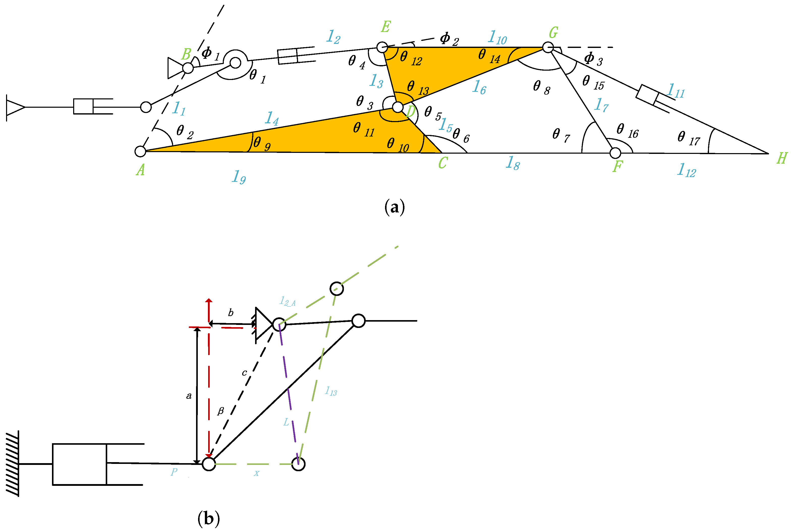
This study proposes a Watt-I six-bar linkage-based rigid mechanism for hand rehabilitation robotics, enhanced through the incorporation of two prismatic joints to achieve triaxial kinematic compatibility with human hand articulation. The developed 1R-2T (one revolute and two translational DoF) configuration is depicted in Figure 2. In particular, taking into account the size of the hand, the rotation of the rotating pair is converted to the horizontal movement of the crank-slider mechanism. A mathematical model is established on the mechanism. The reference coordinate system x 0 o 0 y 0 is established at point A. l i is the length of the connecting link, θ i is the angle between adjacent connecting links, and φ i is the outer angle corresponding to θ i . A B is the fixed link of the robot. The hinges C, F, and H correspond to the proximal knuckle-joint, middle knuckle-joint, and distal knuckle-joint of the human hand joint, respectively. The three points correspond to the finger joints and imitate the movement trajectory of the finger. Thus, we need to solve for these three point motion coordinates.
In order to achieve accurate control of the robot, we need to obtain the driving angle ( θ 1 θ 17 ) of the linkage mechanism. The driving angle θ 1 a is calculated from the slider movement distance in the crank-slider mechanism. In the initial state, the length of the slider push link P, connecting rods L, l 13 , and l 2 _ A is known, and then, the initial value α 0 of angle α can be expressed as follows:
α 0 = a c s ( L 2 + l 2 _ A 2 l 13 2 2 L l 2 _ A )
where a c s is a r c o s . The displacement of the crank slider is p, and the distance between the initial position of the slider and the rotating point B is ( a , b ) . Then, the length of the connecting link L in the figure can be calculated as follows:
L = ( c 2 + ( x P ) 2 2 c ( x P ) s i n ( a r t a n ( b / a ) )
Thus, angle α can be expressed as follows:
α = ( c 2 + L 2 ( x P ) 2 / 2 c L ) 1 / 2 + ( L 2 + l 13 2 l 2 _ A 2 / 2 L l 13 ) α 0
The driving angle θ 1 can be expressed as follows:
θ 1 = θ 1 _ 0 + a
where θ 1 _ 0 is the initial value of angle θ 1 . In order to find the driving angle θ 2 θ 8 , the following two closed-loop vector equations for the four-link mechanism are established:
A B + B E + E D + D A = 0 C D + D G + C F + F C = 0
In closed-loops A B E D , given θ 1 is the drive angle, the other three angles can be found, expressed in Equation (6), as follows:
θ 2 = a c s ( l 4 a c ( l 1 2 + d 1 2 l 2 2 ) + l 1 a c ( l 4 2 + d 1 2 l 3 2 ) ) 2 l 1 l 2 d 1 θ 3 = 2 π θ 1 θ 2 θ 4 θ 4 = a c s ( l 3 a c ( l 2 2 + d 1 2 l 1 2 ) + l 2 a c ( l 3 2 + d 1 2 l 2 2 ) 2 l 2 l 3 d 1 )
For closed-loop C D G F , the interior angles θ 5 θ 8 can be expressed as follows.
θ 5 = 2 π θ 3 θ 11 θ 13 θ 6 = a c s ( l 5 a c ( l 8 2 + d 2 2 l 7 2 ) + l 8 a c ( l 5 2 + d 2 2 l 6 2 ) 2 l 5 l 8 d 2 ) θ 7 = 2 π θ 5 θ 6 θ 8 θ 8 = a c s ( l 6 a c ( l 7 2 + d 2 2 l 8 2 ) + l 7 a c ( l 6 2 + d 2 2 l 5 2 ) 2 l 6 l 7 d 2 )
where d 1 and d 2 are shown in Equation (8).
d 1 = ( l 1 2 + l 4 2 2 l 1 l 4 c θ 2 ) 1 / 2 d 2 = ( l 5 2 + l 6 2 2 l 5 l 6 c θ 5 ) 1 / 2
In Δ A C D , Δ D E G and Δ G F H , the connecting link G H is disconnected as a drive, but it does not affect the angle in the triangle, so the expression of θ 9 θ 17 does not change, which can be expressed as follows:
θ N = α c o s ( l i 2 + l j 2 l k 2 2 l i l j ) , N = 9 17
where l i , l j are the adjacent sides corresponding to θ N , and l k is the opposite side corresponding to θ N . Thus, φ i is determined as shown in Equation (10).
φ 1 = θ 1 + θ 2 + θ 9 , x B 0 θ 1 + θ 2 + θ 9 , x B < 0 φ 2 = θ 6 + θ 10 π φ 3 = θ 7 + θ 16 π
The DH method is used to solve for the positive kinematic coordinates of C, F, and H, demonstrated in Equation (11), as follows:
P C = [ x C , y C ] T = T A C = l 9 s φ 1 l 9 c φ 1 P F = [ x F , y F ) ] T = T A C T C F = l 9 s φ 1 + l 8 s ( φ 1 + φ 2 ) l 9 c φ 1 + l 8 c ( φ 1 + φ 2 ) P H = [ x H , y H ] T = T A C T C F T F H = l 9 s φ 1 + l 8 s ( φ 1 + φ 2 ) + l 1 2 s ( φ 1 + φ 2 + φ 3 ) l 9 c φ 1 + l 8 c ( φ 1 + φ 2 + l 1 2 c ( φ 1 + φ 2 + φ 3 ) )
where a c is a c o s , c is c o s , and s is s i n . φ i is a function of θ i , and θ i is a function of the actuation displacement x and the link length l i . Among them, l 2 and l 11 are driven by the translational DoF. Thus, C, F, and H can be expressed as follows:
P C = f 1 x ( x , l 2 , l 11 ) f 1 y ( x , l 2 , l 11 ) P F = f 2 x ( x , l 2 , l 11 ) f 2 y ( x , l 2 , l 11 ) P H = f 3 x ( x , l 2 , l 11 ) f 3 y ( x , l 2 , l 11 )
Therefore, the precise control of finger joints can be achieved through the movement of three translational DoF. Since the lengths of other links are fixed and the angles can be calculated by the links, the inverse kinematic equations of the three moving DoF can be obtained as follows:
x = f 1 ( l 2 , l 11 , x C , y C , x F , y F , x H , y H ) l 2 = f 2 ( x , l 11 , x C , y C , x F , y F , x H , y H ) l 11 = f 2 ( x , l 2 , x C , y C , x F , y F , x H , y H )
Since there is a coupling and nonlinear relationship in the inverse kinematics of the linkage mechanism, we decided to fit the control law of its actuation with higher-order polynomials.

2.1.3. Soft Structure Design

Mechanical configuration design and soft material selection are critical for rehabilitation robots’ functional efficacy. Following material preparation comparisons from soft robotics research [41,42,43] (Table 1), silicone rubber demonstrates superior biocompatibility, softness, fatigue resistance, stability, and manufacturability. Comparatively, TPU exhibits higher rigidity with compromised fatigue performance, requiring specialized medical processing, while SMP necessitates external stimuli activation and suffers from limited lifecycle stability. So we finally chose silicone as the raw material for the flexible part of the rehabilitation robot.
Silicone exhibits tunable hardness and demonstrates variable elongation at break, with the mechanical properties of Ecoflex-series liquid silicone rubber quantitatively characterized in Table 2. Guided by the functional specifications of compliant robotic components, Ecoflex 10 is selected as the fabrication material.
The constitutive model is used to describe the relationship between the bending angle of the soft finger joint and the pressure. The material parameters of the silicone rubber constitutive model have a great impact on the finite element optimization results, so it is very important to select the appropriate constitutive model. The Yeoh model, Mooney-Rivlin model, and Ogden model are commonly used in engineering to calculate the parameters of the silicone rubber constitutive model. Among them, the Yeoh model is simple in structure, convenient for calculation, and can characterize the material properties of rubber in the case of large deformation well, so it is adopted in this paper. Its expression is as follows:
W = i N C i 0 ( I i 3 ) i + K = 1 N 1 d k ( J 1 ) 2 k
where N is the order of the strain energy density function, and C i 0 and d k are material parameters. For incompressible material J = 1 , the Yeoh model can be simplified as follows:
W = i N C i 0 ( I i 3 ) i
In order to speed up the calculation and simplify the simulation optimization process, the second-order expansion of the Yeoh model is usually used to describe the mechanical properties of the hyperelastic material, where N = 2 is substituted into Equation (15) to obtain the second-order expansion expression of the Yeoh model as follows:
W = C 10 ( I i 3 ) + C 20 ( I i 3 ) 2
where C 10 = 0.15 , C 20 = 0.00086 is to be used as the material parameter of the Yeoh model for finite element simulation.
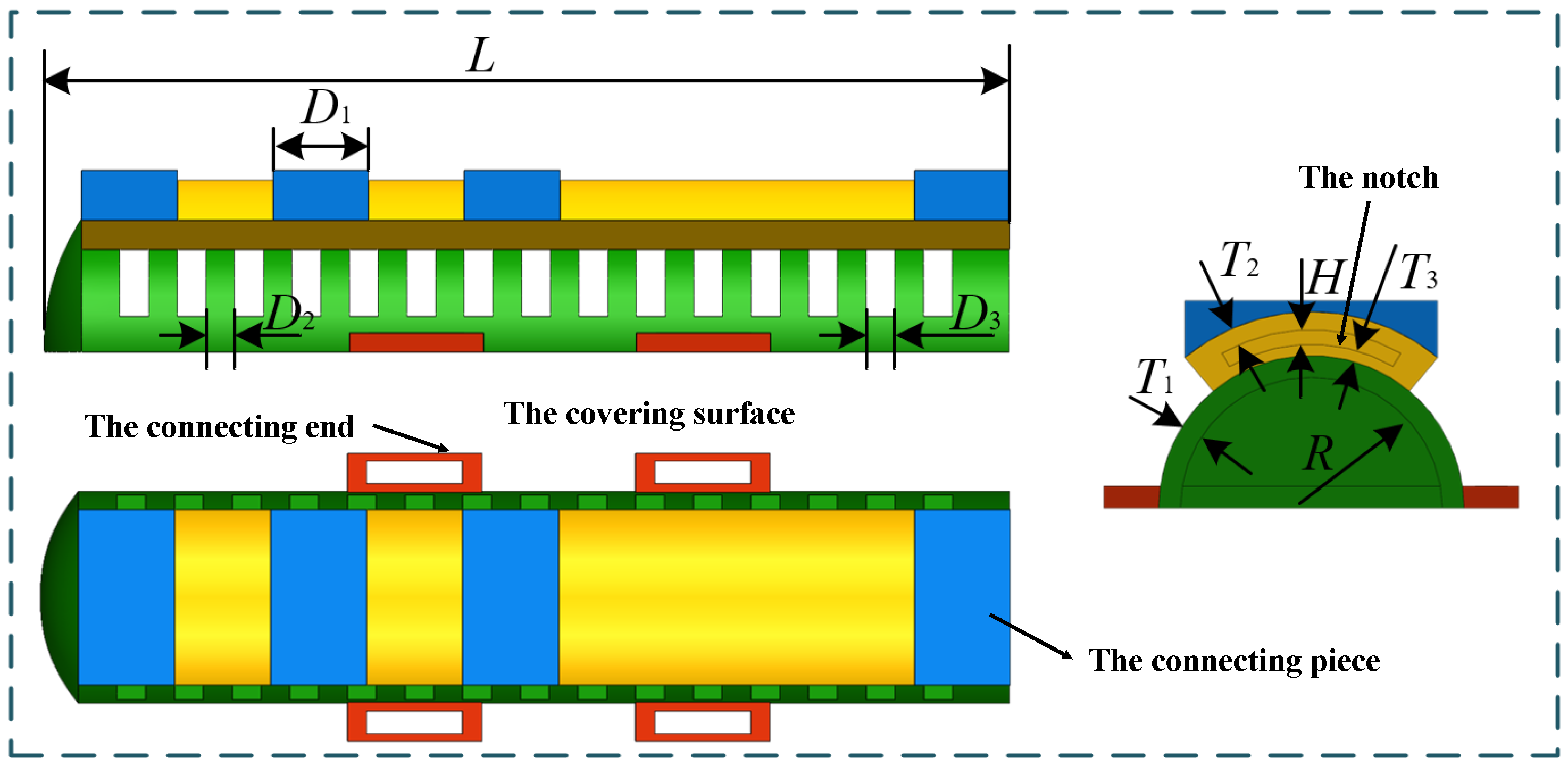
Figure 3 shows the structure of the soft part, which is mainly composed of the following four parts: the connecting end for fixing with the finger, the covering surface for covering the finger, the notch for placing the sensor, and the connecting piece for the rigid–flexible connection the symbolic meanings in Figure 3 are presented in Table 3. The soft part of the rigid–soft hand function rehabilitation robot is used as a protective element for the human hand and a supporting element for signal acquisition.

2.2. Dimension Optimization

2.2.1. Grasping Motion of Human Hands

For realizing the bionics of the hand function rehabilitation robot, a human hand movement trajectory that accords with the normal hand movement law should be obtained, so that the patient can be efficiently guided to complete rehabilitation training. On the basis of anthropometry and hand dynamic dimensions, the index finger is selected as the track acquisition object, and the specific finger length is shown in Table 4.
Three groups of image data are collected for each group of the grasping experiment to improve the stability and reliability of the trajectory data. The data are analyzed by motion statistics and regression analysis. The optimal data are selected as the final fitting data according to the smoothness of the trajectory.
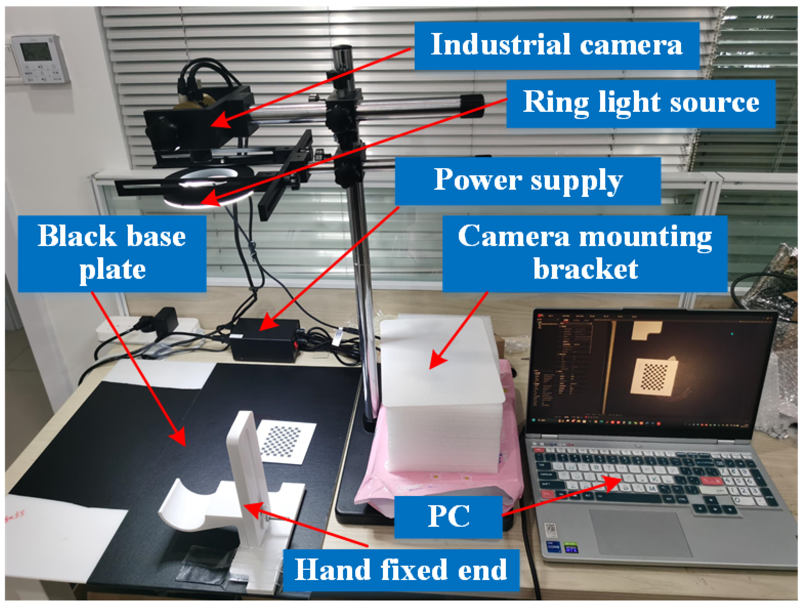
Acquisition system: The selection of suitable experimental equipment can improve the reliability and stability of the vision acquisition system. As shown in Figure 4, this study selects a Dahua A3502CG100 industrial camera (Dahua Technology, Zhejiang, China) and its auxiliary 8 mm lens as the image acquisition element and adopts a ring light source to reduce the interference of ambient light to ensure image stability. The printing of the grab cylinder is completed using a 3D printer, and the hand fixation module is designed to complete the fixation of the wrist joint of the hand during grasping.
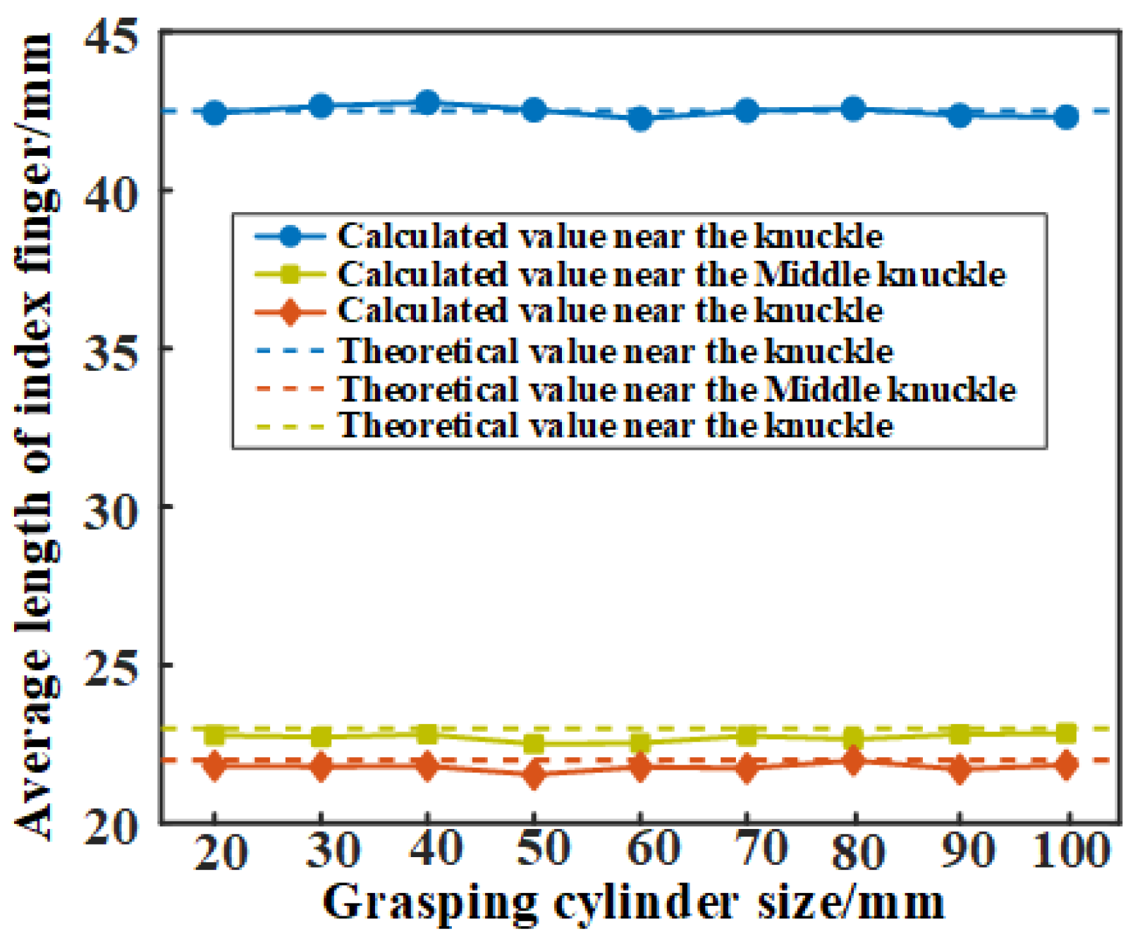
Grasping data: The coordinates of the joint points when the index finger grasps the cylinder are collected. Each group of crawl data is collected 3 times. When the trajectory similarity reaches 90%, the group of data is confirmed to be valid. We measured the mean (Figure 5) and variance (Figure 6) of the length of each finger segment when grasping objects of different sizes. In each grasping action, the length of each segment of the index finger fluctuates within a small range. The variance of finger length fluctuates between 0.05 mm and 0.335 mm, showing a relatively stable feature. This confirms the validity and reliability of the collected index finger trajectory data.
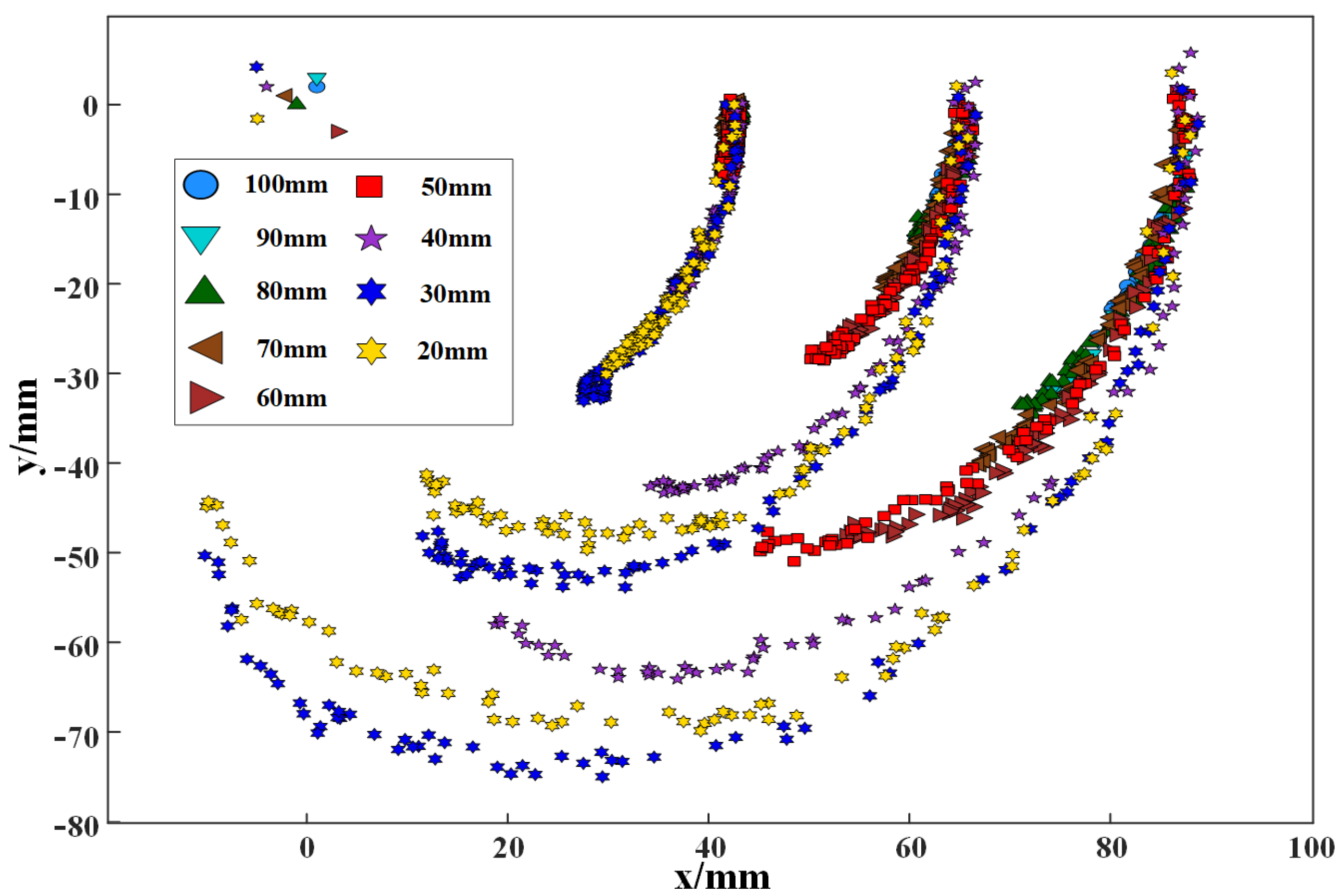
After completing the validation of the data, the data were collated and fitted. A higher-order equation was used to fit the data during the grasping of cylinders ranging from 20 to 70 mm. Figure 7 shows a schematic diagram of all trajectories, where the proximal knuckle has a small range of motion and the trajectories basically coincide, while the distal knuckle and the middle knuckle have a large range of motion and the trajectories change significantly when grasping cylinders of various sizes. Therefore, in order to effectively guide the robot mechanism design and motion planning control, it is necessary to deal with the overall fitting and individual fitting of these trajectories.
The trajectories of the proximal, middle, and distal knuckles in grasping a cylinder of various specifications were considered as a whole and fitted using the higher-order equations.
y 1 = 2.611 x 2 + 13.82 x 12.47 y 2 = 0.1807 x 7 + 1.849 x 6 + 6.245 x 5 + 7.373 x 4 + 0.1519 x 3 + 2.922 x 2 + 22.14 x + 29.08 y 2 = 1.498 x 6 + 8.791 x 5 + 15.98 x 4 + 5.509 x 3 0.8821 x 2 + 22.73 x 44.59
where y i denotes the fitting equations. After fitting the overall trajectory, it is necessary to fit the trajectory for each grasp from 20 mm to 70 mm, as shown in Table 5. These fitted trajectory equations of each joint lay the foundation for the scale optimization of the robot configuration and the design of the actuator control law.

2.2.2. Dimension Optimization of the Rigid Structure Based on MM

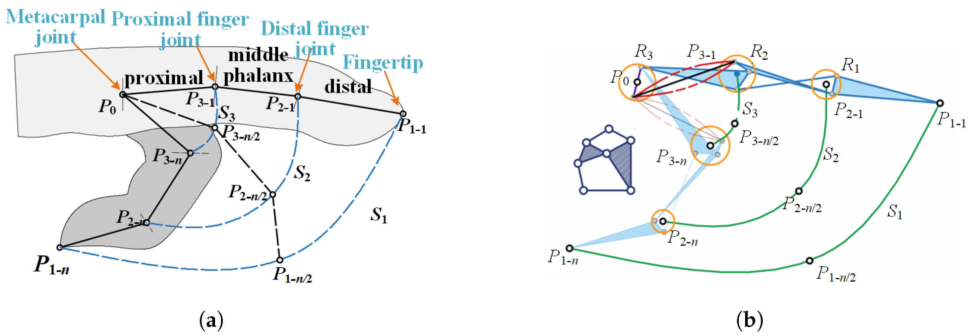
On the basis of manual trajectory acquisition and mechanism modeling, an optimal design and motion control method for the single/multi-DoF mechanism based on hierarchical constraints is proposed. As shown in Figure 8a, in order to have a good match between the rigid structure and the finger movement, the reference points of the rigid structure should be made to be close to the trajectories of the proximal digital joint, the distal digital joint, and the fingertip. Firstly, the single-degree-of-freedom configuration design is carried out. At this time, there is only one degree of freedom in the Watt type I six-bar linkage-based mechanism, as shown in Figure 8b. The optimal design of the single-degree-of-freedom rigid body mechanism should be divided into the following four steps:
  • Selection of initial conditions: Select the basic diagram of the Watt-I six-bar linkage-based mechanism, and on this basis, select the appropriate frame and the reference point matching the finger joint. For the fingertip reference point, if the hinge point is selected as the fingertip point, the number of connecting rods between it and the frame should not be less than 3. If a point on the connecting rod is selected as the fingertip point, the number of connecting rods between it and the frame should not be less than 2. For hinge points corresponding to other finger joints, the number of linkage points located at the proximal knuckle-joint and the middle knuckle-joint are successively reduced from the frame. In particular, the selection of the hinge point is not unique, as it is necessary to establish the initial condition parameter library from which the initial condition is called.
  • Determination of the initial parameters for the link length: With the relative position parameters of the hinge points as the initial parameters, the initial coordinate points P 3 1 , P 2 1 , and P 1 1 and the end coordinate points P 3 n , P 2 n , and P 1 n of the proximal knuckle-joint, the middle knuckle-joint, and the distal knuckle-joint were taken as references, the joint constraint range was set, and the hinge coordinate points were obtained by randomly selecting points within the joint range. The initial rod length, driving angle and frame angle of the linkage mechanism are obtained under less constraint conditions, which are used as the initial conditions for subsequent optimization analysis.
  • Optimal design based on hierarchical constraints: The number of constraint points on the three tracks is increased in layers to form a constraint envelope surface. The IABC algorithm is used to further optimize the rod length parameters. Through the gradual increase of constraint points, the center locus of the joint range obtained by the link length parameter is gradually close to the overall fitting locus in Section 3.1. When enough constraints are given and the variation of each rod length is within a small range, the design is completed.
  • Continuity analysis of mechanism motion: In the above design process, it is necessary to further judge the continuity of the movement of the mechanism; on the one hand, the movement of the connecting rod mechanism itself is continuous, and on the other hand, the joint range composed of the hinge points can pass the constraint points in order.
When applying the above-mentioned mechanism optimization design method to the design of the rigid body part, the Watt type I six-link configuration is first selected, and the initialization range of each link is set, as shown in Table 6. According to the previous calculation of robotics, the three points C, F, and H should be located in the envelope of the target trajectory during the optimization process, and at the same time, the robot needs to maintain the integrity of the configuration during the movement.
The Artificial Bee Colony (ABC) algorithm is a swarm intelligence-based optimization method that achieves localized refinement through division-of-labor behaviors among bee agents, enabling global optimization in high-dimensional complex search spaces. Key advantages encompass algorithmic simplicity, robust global exploration capacity, parameter insensitivity, and adaptive versatility. Limitations include slower convergence with comparatively weaker local search capabilities, problem-specific dependency, and initial value sensitivity. These constraints motivate our proposed Improved ABC (IABC) algorithm.
  • Improved honey source initialization: While ABC’s stochastic initialization fosters population diversity, it compromises convergence efficiency. Our method strategically employs datasets P and q , where initialization probabilistically allocates 50% of solutions from these datasets. During new source exploration, a parity-check mechanism enforces selection from P and q , followed by post-selection dataset shuffling with 50% solution redistribution. This mechanism enhances algorithmic convergence while maintaining solution diversity. The initialization procedure is as follows:
    O i = P , i / 2 = 1 q , i / 2 = 0
    where P is a randomly generated odd-numbered dataset, and q is a randomly generated even-numbered dataset.
  • Improved employed bee: The conventional ABC algorithm employs randomly selected coefficients ( φ [ 1 , 1 ] ) during honey source exploration, introducing stochasticity into the optimization directions. To address this limitation, an inertia weight w ( j ) is integrated into the honey source localization and colony positional update equations as follows:
    X i j = x i j + w ( j ) φ ( x i j x ( k j ) ) , j k
    The inertia weight integration enhances algorithmic capabilities by prioritizing global exploration during initial iterations and local exploitation in later phases. To operationalize this dual-phase optimization, we propose a logarithmically decaying nonlinear inertia weight strategy, mathematically expressed as follows:
    w ( j ) = w m a x ( w m a x w m i n ) l o g N j
    where N is the maximum iterations, w m a x is the maximum value of weight, and w m i n is the minimum value of weight.
  • Improved follower bee: Conventional local search implementations employ stochastic single-dimensional selection during source position updates, utilizing probabilistic field adjustment via [ 0 , 1 ] -range random numbers. This methodology compromises search efficiency and convergence rates. Our improvement introduces a dual-strategy framework combining equidistant exploration with existing stochastic search rules. As formalized in Equation (20), the enhanced algorithm performs parallel search path generation through randomized interval domains (I and k) while maintaining roulette-based employed bee selection. A greedy selection mechanism compares solutions from equidistant cyclic generation against stochastic search outputs, retaining superior nectar sources.
    X i j = b e s t ( x i j + a ( x i j x i k ) , x i j ± I k x i j )
To validate the performance of the improved IABC algorithm, comparative experiments were conducted against the conventional ABC algorithm and genetic algorithm (GA) using eight standard test functions. These include single-modal, multi-modal, and composite benchmark functions. Single-modal functions evaluate single-target problem-solving capabilities for preliminary testing, while multi-modal functions assess global search performance in multi-solution scenarios. Composite functions test adaptability to complex multi-objective and multi-constraint problems. Detailed function specifications and configurations are provided in Appendix A. Parameters were set to N P = 100 (colony size), m a x C y c l e = 100 (maximum number of iterations). Genetic algorithm parameters were set to M = 100 (population size) and G = 100 (termination evolutionary generation), P c = 0.5 (crossover probability), P m = 0.05 (mutation probability). The 12th Gen Intel(R) Core(TM) i7-12700H was used to calculate the algorithm. The convergence generation ( C G ), calculation time, and final objective function values of each algorithm are shown in Table 7.
The IABC algorithm convergence results are accurate and convergence speed is the fastest and can be given in the shortest time to meet the requirements of the solution. Therefore, the IABC algorithm is used to optimize 13 link parameters (Table 4). In the ABC algorithm, the number of honeycombs is set to 100, the number of honeybees is set to 100, and the maximum number of iterations is set to 100.
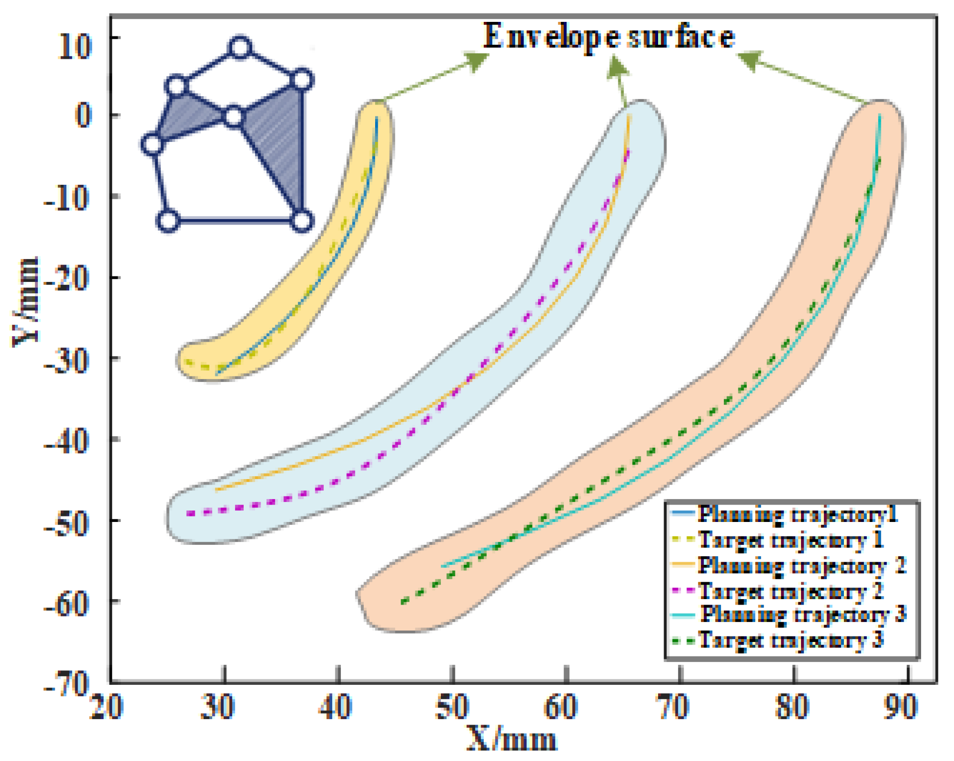
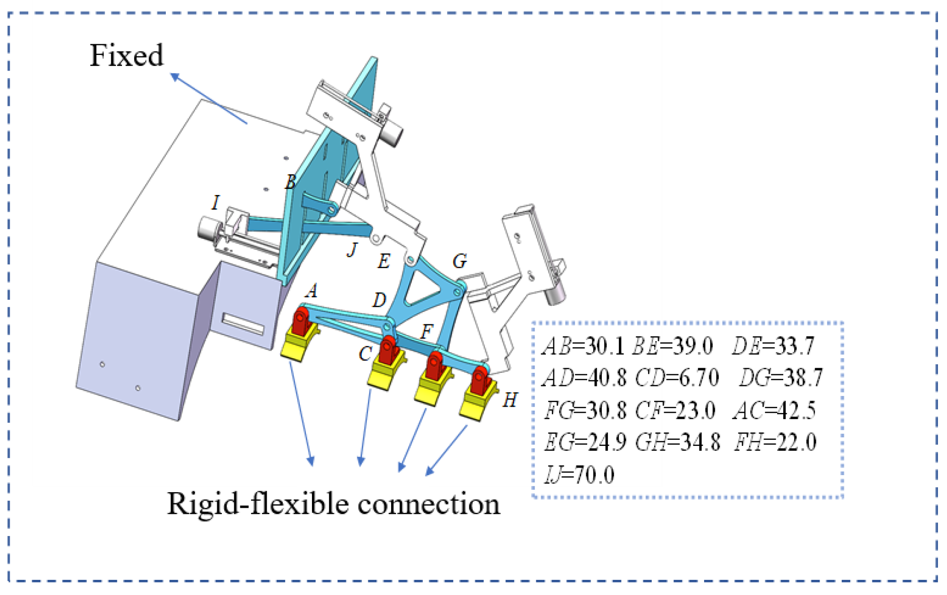
As shown in Figure 9, the trajectory obtained by optimization lies within the dynamic envelope of the target trajectory. A comparison of the nodal trajectories indicates that the two curves basically coincide with each other, except for the fitting error at the initial position. Figure 10 shows the optimized rigid body part of the robot and the length of each link. The structure exhibits similarity to the human hand, presents the characteristic of a stable structure, and meets the bionic requirements in the design. In this configuration, the initial driving angle is 128.43°, so the initial configuration basically meets the design requirements.

2.2.3. Dimension Optimization of Soft Structure Based on ABAQUS

In this paper, finite element simulation software is used to optimize the soft structure dimension of the rigid–soft integrated hand function rehabilitation robot. ABAQUS 2020 software is selected for the parameter optimization of the soft part. Compared with other finite element simulation software, ABAQUS can provide more accurate simulation results for the problems related to nonlinear material behavior and large deformation. For ensuring the simulation efficiency and the convergence of the simulation, the soft part is simplified and modeled using the hyperelastic material Yeoh model ( C 10 = 0.15 , C 20 = 0.00086 ), and the main parameters are selected on this basis. The structural parameters and value range of the soft part are determined in the consideration of the advantages and disadvantages of each parameter and the hand data of a normal human, as shown in Table 8.
On the basis of the structural parameters of the soft body, the main structural parameters, including the thickness of the human hand cavity T 1 and the thickness of the sensor cavity T 2 , are optimized through simulation experiments. The thickness of the human hand cavity T 1 determines the protection of the human hand, and the thickness of the sensor cavity T 2 affects the sensing accuracy of the sensor. Therefore, the simulation optimization design of T 1 and T 2 is required. The simulation method is the single-factor controlled variable method, and the optimization of the software structure is realized by changing individual structural parameters.
Thickness optimization of hand cavity: The simulation analysis is carried out by changing the parameter T 1 = 1 (the thickness of the hand cavity), and the protection effect on the human hand is realized by changing the thickness. As shown in Figure 11a, when T 1 = 1 , the soft part breaks during the simulation. In Figure 11b, when T 1 = 2 , neither failure deformation nor an insufficient bending angle exist. From Figure 11c, when T 1 = 3 , the bending angle of the soft part cannot meet the requirements, although no failure, such as a fracture, occurs. Therefore, T 1 = 2 is the optimal solution for this configuration.
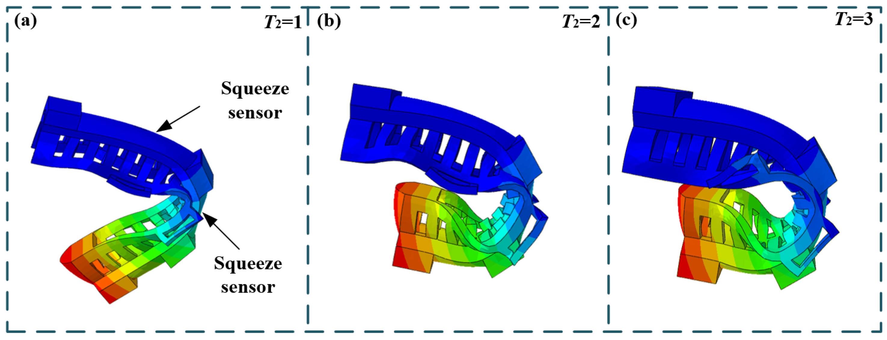
Thickness optimization of the sensor cavity: The simulation analysis is conducted by changing T 2 (the thickness of the sensor cavity). The upper thickness of the sensor cavity on which the software part is installed is changed, so that the sensor will not be affected during deformation. As shown in Figure 12a, when T 2 = 1 , the upper thickness is considerably small, the sensor is squeezed during deformation, and the accuracy of the sensor is influenced. In Figure 12b,c, when T 2 = 2 , 3 , the soft part does not cause any compression to the sensor; however, when T 2 = 3 , the bending angle of the soft part is larger. Accordingly, T 2 = 3 is the optimal solution for this configuration.
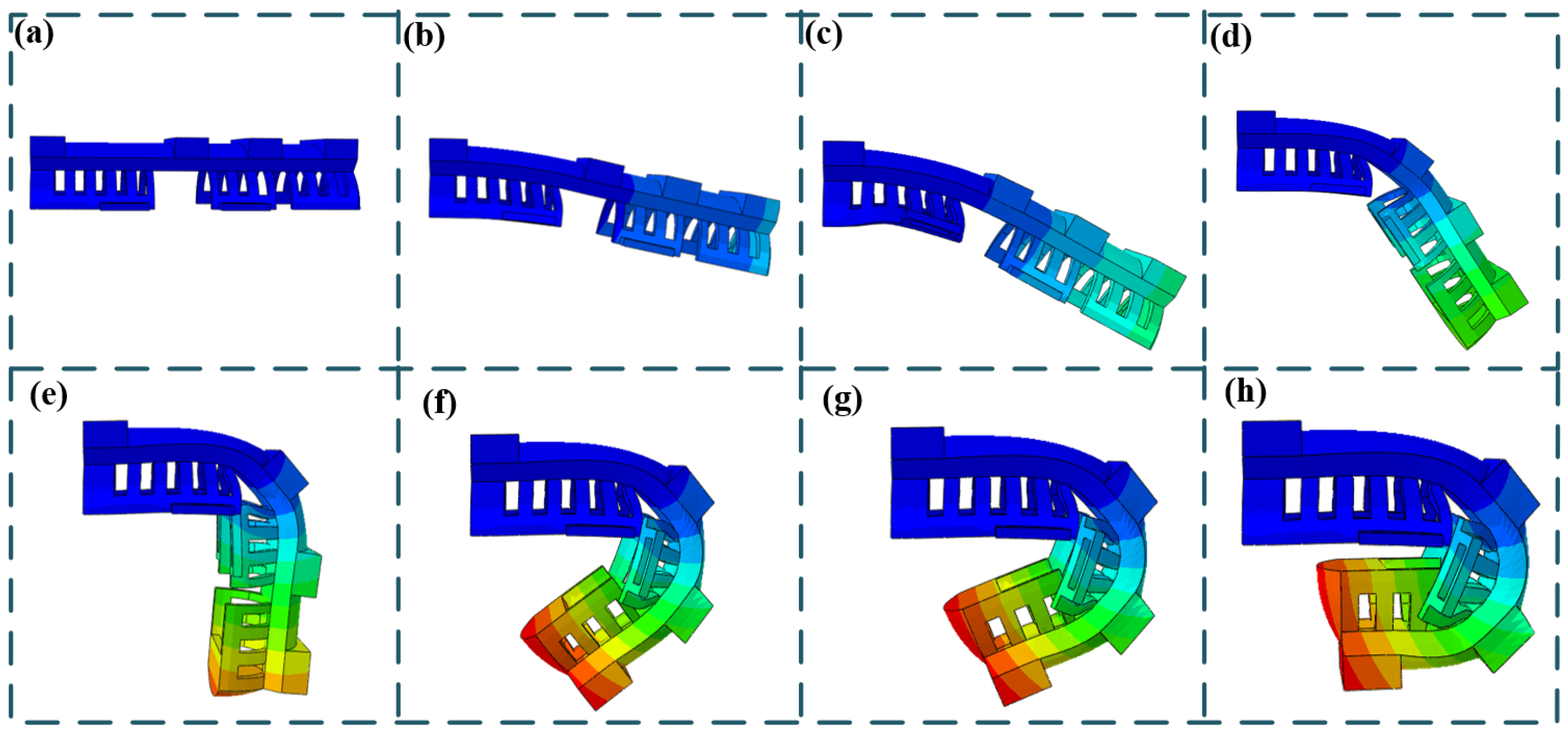
Further optimization: After the parameters T 1 and T 2 are optimized, the structure requires further optimization so that the envelope surfaces on both sides of the soft body are not separated from the hand during bending, as depicted in Figure 11 and Figure 12, thus losing the protection for the hand. The specific design is shown in Figure 13. The envelope surfaces on both sides at the joint are broken so that the soft parts do not interfere, and the specific optimized breaking distances of τ are B 1 = 17 mm and B 2 = 17 mm. After the size of the soft part is identified, the position of the rigid–soft joint needs to be determined. According to the length relation of the finger in human anatomy and the length of the index finger selected in Section 3.1 of this paper, the length of each joint tip is C 1 = 42.5 mm , C 2 = 23.0 mm , C 3 = 22.5 mm . On the basis of the final software part optimization parameters, the simulation sequence diagram shown in Figure 14 is obtained.
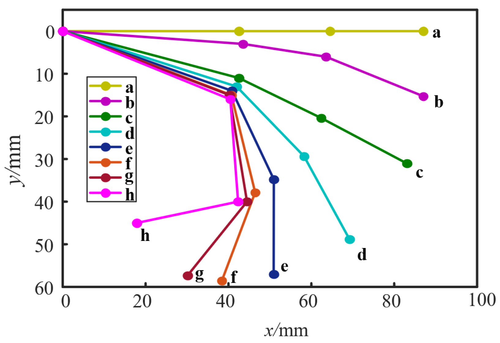
Figure 14 demonstrates that under the action of pressure, each joint bends in turn. The change trend diagram of each joint is obtained. The coordinate position of each joint and fingertip in the sequence diagram is identified to obtain the bending trajectory diagram of the software part, as shown in Figure 15. In the process of bending the soft body, the bending amplitude of the proximal and distal finger joints approximately meets the linear relation, while the bending rule of the finger is approximately satisfied. The rehabilitation requirement of the hand of the patient can be met, so that the design of the soft body part of the rigid–soft integrated hand function rehabilitation robot is finished.

2.3. Motion Planning and Simulation

2.3.1. Design of Motion Planning

Following the determination of the rigid-body mechanism, we investigate motion control planning for the 3T rehabilitation robot. To circumvent complex force control and sensors, a feedforward open-loop control scheme is implemented. By directly regulating the translational joint position, mechanism trajectory synchronization with finger kinematics is achieved, enabling rehabilitation training. This necessitates the derivation of driving control equations, where different trajectories are addressed through parametric modeling via higher-order polynomial Equation (21).
Y j = i = 0 n α j , i x i , j = 1 , 2 , 3
where Y j is the driving control equation, and α j i is the driving equation coefficient.
Then, the higher-order function coefficients α j i undergo parametric optimization. Kinematic envelopes are established at the proximal knuckle-joint, middle knuckle-joint, and distal knuckle-joint for systems S 1 and S 2 . The corresponding driving control equations are matched in the kinematic envelopes. This transforms the constrained envelope surface matching into an unconstrained optimization problem by minimizing statistical moment discrepancies (the mean and variance) in joint coordinates. Thus, we need to apply position and degree constraints to the linkage mechanism. When parameter λ 1 undergoes dynamic adjusting and λ 2 = 1 is fixed, the distal knuckle-joint trajectory is optimized. Upon achieving fingertip optimization convergence, parameter λ 2 undergoes dynamic adjusting and λ 1 = 1 is fixed to optimize the proximal knuckle-joint and the middle knuckle-joint trajectories. This hierarchical process holistically achieves full-finger MM, formalized by the multi-objective optimization function in Equation (22), as follows:
f m i n = λ 1 g ( m ( E 1 ) , v ( E 1 ) ) + λ 2 ( h ( m ( E 1 , E 2 ) , v ( E 1 , E 2 ) ) ) 2 E i = j = 1 n | S i j s i j | , i = 1 , 2 , 3 S t . D g , i D i W g = 1
where m is the mean function; v is the variance function; λ 1 and λ 2 are the dynamic parameters, which are dynamically adjusted according to function g during the period from 0 to 1; S is the actual trajectory; D is the trajectory achievement degree; and W g is the robot position constraint. The specific optimization process is similar to the previous optimization design method of the rigid body mechanism. The difference is that the above optimization process realizes the MM of the fitting trajectory by adjusting the length of each link. The object to be optimized in motion control planning is the coefficients of the higher-order function.

2.3.2. Calculation of the Motion Trajectory

The purpose of this section is to verify the effectiveness of the proposed motion planning algorithm with the 40 mm motion planning in the fitted trajectory. The motion planning design requirements and constraints shall include trajectory constraints (minimum constraints), and the reference point H on the robot shall be as close as possible to the trajectory acquired when the human fingertip is held at 40 mm. For the position of the reference points C and F on the robot, the range constraint should be concentrated on the small range of the near-phalangeal joint and the far-phalangeal joint trajectory of the human hand, and the set of hinge points forms the equivalent joint to fit the motion trajectory of the human hand.
To ensure the accuracy of robot motion planning, this study assumes that the variation law of three moving pairs is a cubic function, and its polynomial coefficients need to be determined. The constant terms of these functions can be measured directly from the initial value of the connecting rod length, so there are nine. The polynomial coefficients need to be determined. Therefore, the IABC algorithm is used to optimize nine undetermined coefficients. In the IABC algorithm, the number of honeycombs is set to 100, the number of honeybees is set to 100, and the maximum number of iterations is set to 100. The optimized parameter ranges and final results are detailed in Table 9.
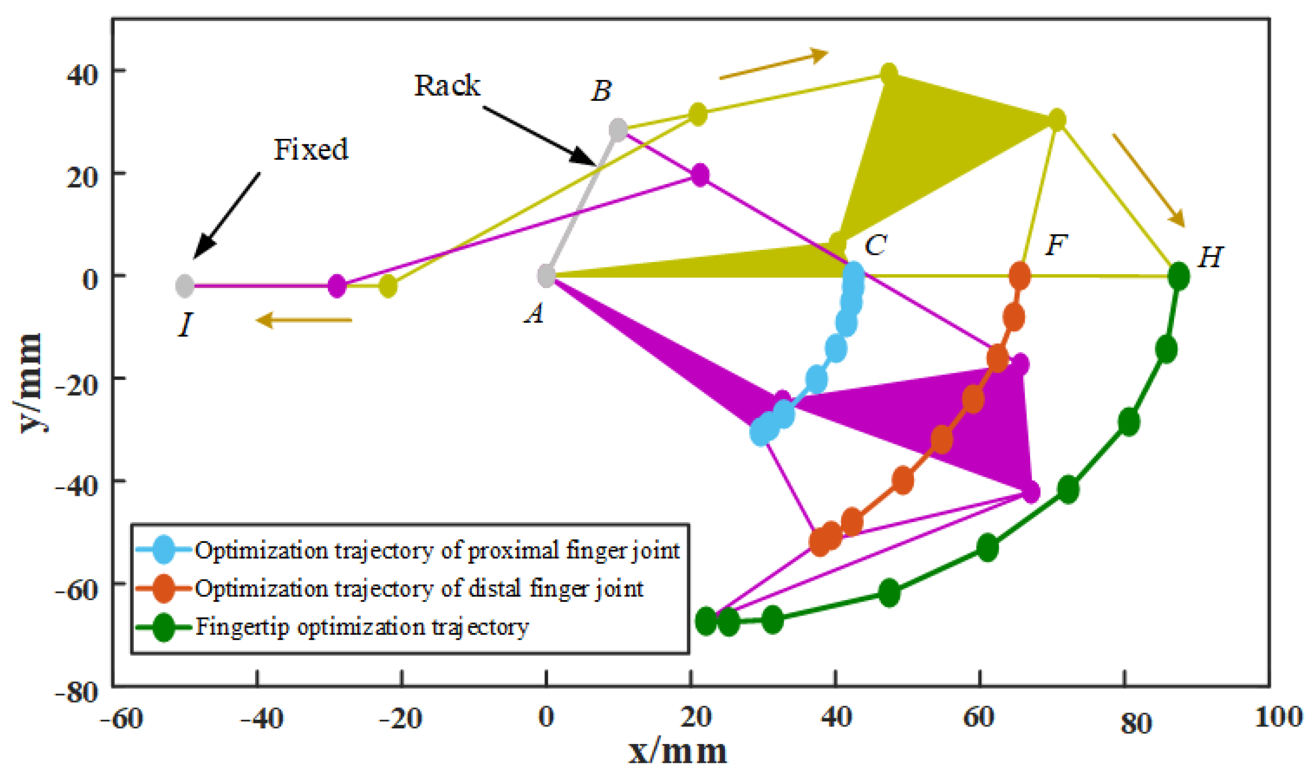
After the final motion control function is obtained, it is applied to the actual control of the robot, and the robot motion planning diagram shown in Figure 16 is obtained. Hinge points C and F move within the center of the target trajectory with a minimum equivalent envelope radius of only 1.33 mm, which is sufficient for trajectory constraints at the distal and proximal finger joints. The trajectory of the fingertip of point H is basically consistent with the trajectory of the target, which shows that the obtained motion control scheme is effective and feasible.

2.3.3. Motion Simulation

For verifying the correctness of the mathematical model of the rigid body part of the rehabilitation robot, a simplified 3D simulation model of the robot is established in accordance with the optimized connecting rod length of each part. The simplified 3D model is imported into Adams. On the basis of the theoretical calculation results, the control data during the rehabilitation training of the robot are determined and input into Adams for setting, and the positions and trajectories of C, F, and H obtained by simulation are compared with the theoretical calculation solution.
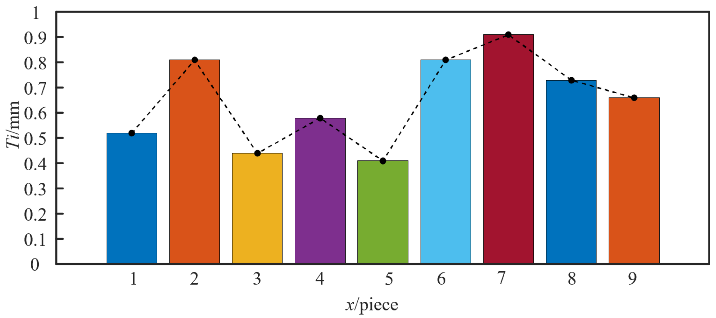
The 40 mm control curve optimized by the algorithm is used to control the rotating and moving pairs, nine positions in the collection and target track sets are randomly selected, and the error T j of the ordinate under the same abscissa is calculated. As shown in Figure 17, in the randomly selected positions, the error of the ordinate is small, and the accumulated error of 40 mm is 5.87 mm, which can meet the control requirements. Therefore, it is proved that the control equation and the motion control method are accurate and effective.

3. Experiment Result

3.1. Prototype Construction

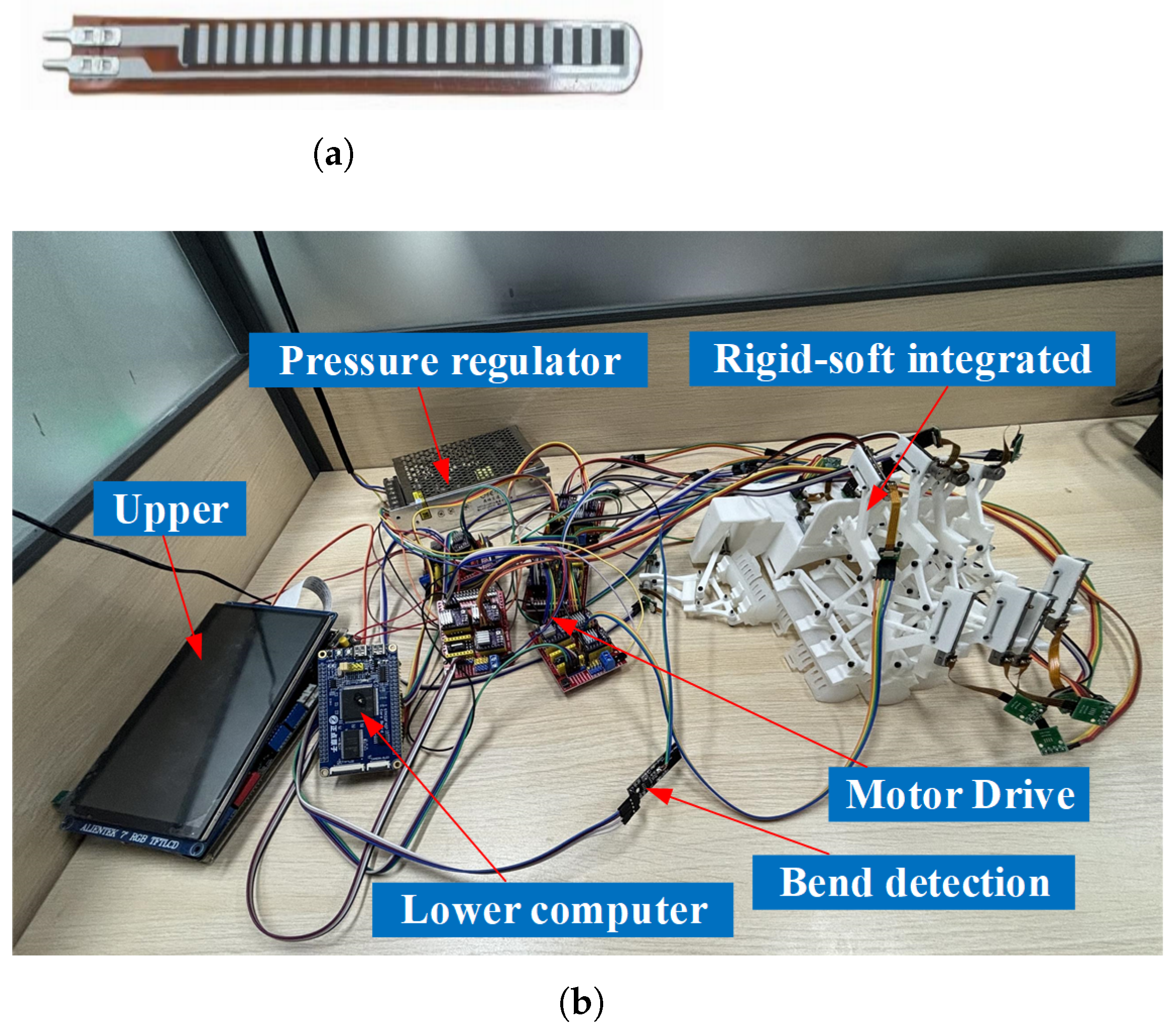
The robotic structural framework employs 3D-printed linkage assemblies and specially shaped components for precision manufacturing. The soft part adopts the method of integrated mold forming. Each finger requires distinct rigid–soft configurations. Then, the robot is integrated with the electromechanics of the stepping motor and curvature detection sensor, and the system is synchronized for motion control. The curvature detection sensor uses the highly sensitive and reliable Flex one-way bending sensor (Figure 18a). This sensor consists of variable resistors and can accurately measure the bending angle of the finger by monitoring the change of the resistance value. Initial durability testing of flexible elements through >1000 cyclic flexion trials demonstrated no structural degradation or rebound force attenuation, confirming long-term stability during sustained rehabilitation protocols. In addition, the soft component’s cost-effectiveness facilitates on-demand replacement. The finalized prototype configuration is illustrated in Figure 18b.

3.2. Performance Test

After the prototype was manufactured, the performance of the rigid–soft coupling hand rehabilitation robot was tested in terms of trajectory matching and mechanism stability. In addition, we compared it with other hand rehabilitation robots (as shown in Table 10).

3.2.1. Rehabilitation Trajectory Matching

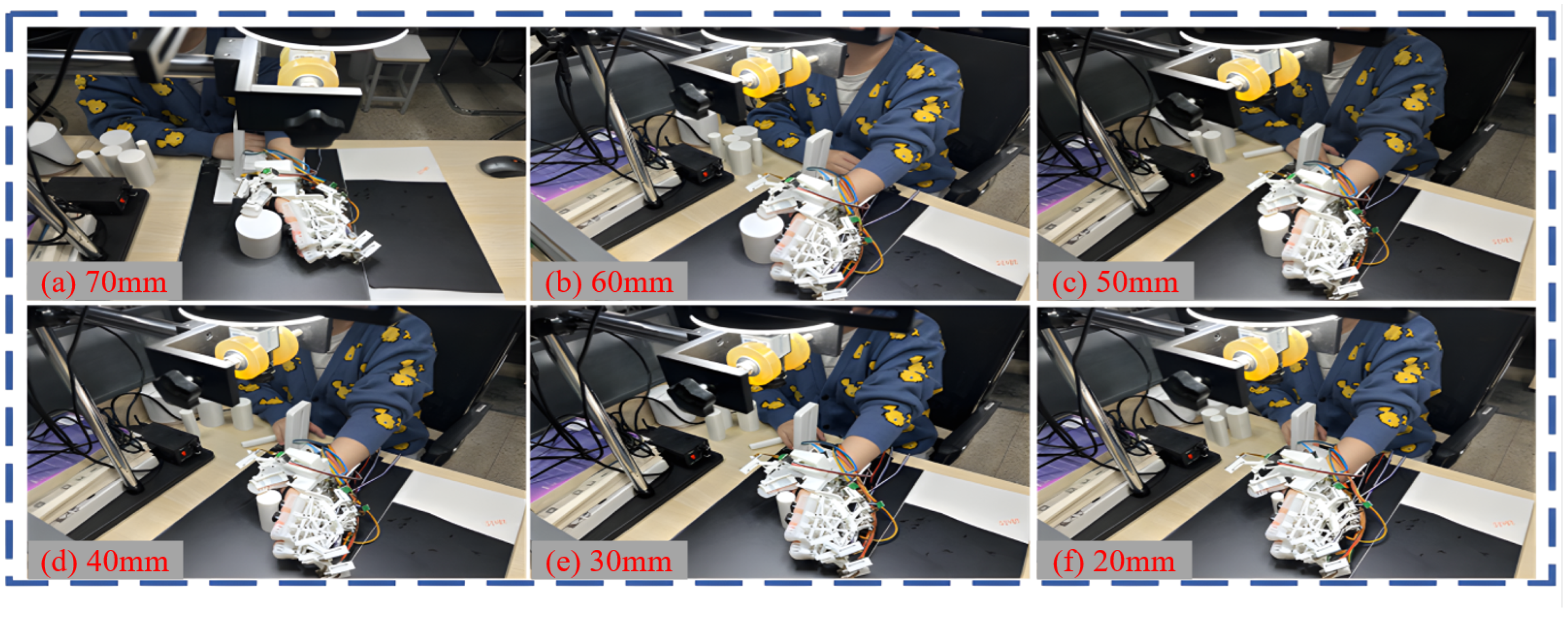
This study evaluates motion control fidelity and trajectory alignment in rigid–soft coupled hand rehabilitation robots by comparing hand trajectories during robotic traction against baseline trajectories from Section 2.3.1. As demonstrated in Figure 19, the trajectory acquisition system documents cylindrical grasping motions (20–70 mm diameters) under robot-assisted rehabilitation, enabling the quantitative assessment of control precision and therapeutic trajectory congruence with biological movement patterns. Nine reference markers were designated on the robot’s rigid joints for comparative trajectory analysis against human hand motion profiles derived in Section 2.3.1. We divide the motion trajectory into 100 position points at the same time interval and calculate the error with the corresponding theoretical points. The error is calculated as follows:
e k = 1 N M i = 1 N j = 1 M | s k , i , j s ^ k , i , j |
where e k is the error of the k-th reference markers. N is the number of participants and M is the number of track points. s represents the measured value and s ^ represents the theoretical value.
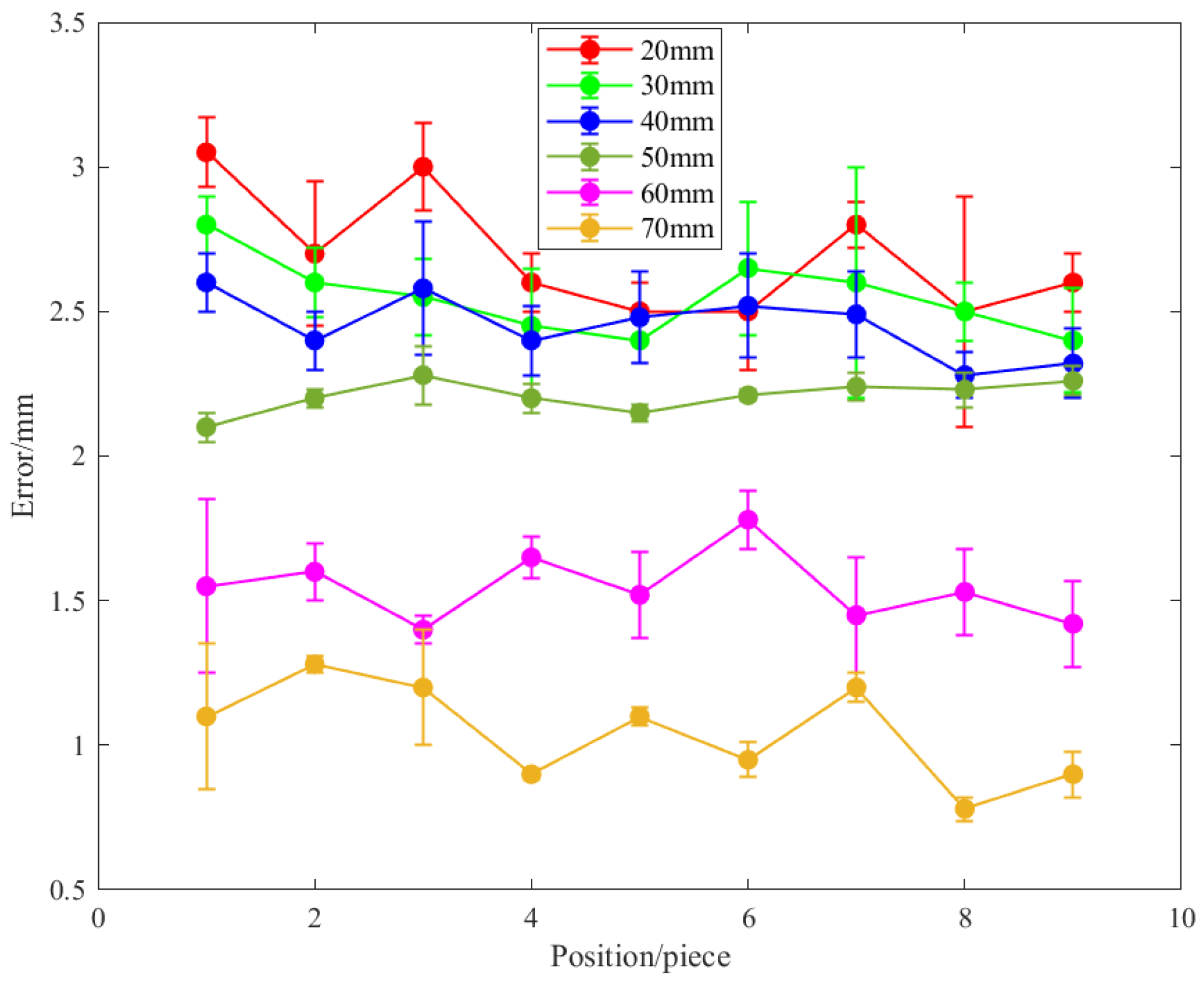
Experimental validation involving 10 participants demonstrated the alignment between empirical measurements and theoretical predictions (Figure 20), with peak positional deviation observed in 20 mm cylindrical grasping trajectories (3.17 mm) and minimal error in 70 mm configurations (0.74 mm). In different grasping diameters, the trajectory errors of the nine reference markers are basically consistent. After repeated rehabilitation training, the trajectory error did not change significantly. In addition, we use the angle values measured by the Flex bending sensor to compare with the simulation results in Section 2.3.2. The error value can be maintained within 5 degrees, but with the increase in bending amplitude, the error obviously increases (Figure 21).

3.2.2. Mechanism Stability

Robotic stability constitutes a critical determinant for ensuring patient safety during hand rehabilitation therapy. Output force consistency and magnitude during actuation directly influence both patient comfort and perceived safety, while object-specific grasping requirements introduce trajectory deviations that may compromise therapeutic efficacy. These operational interdependencies necessitate the implementation of a comprehensive system validation. Thus, we evaluated fingertip contact pressure and daily necessities grasping performance in the rigid–soft hand function rehabilitation robot.
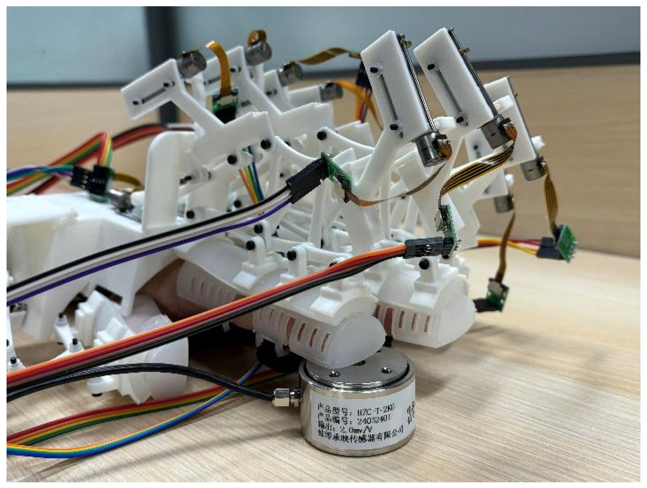
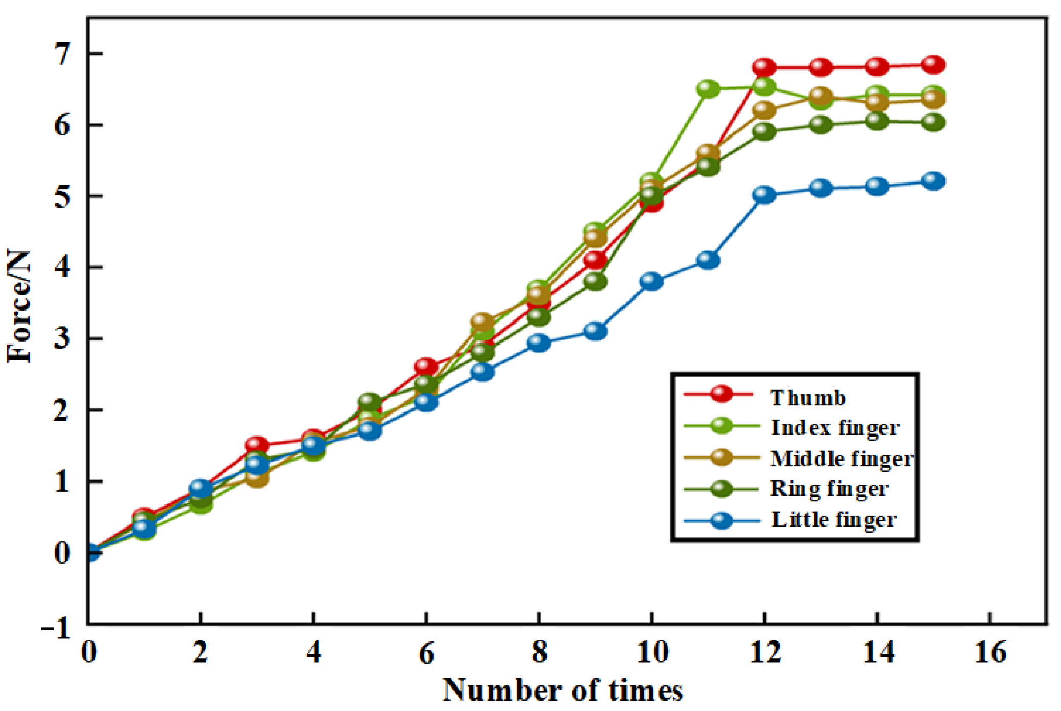
As illustrated in Figure 22, the rigid–soft rehabilitation robot is worn on the hand, and the tip of the finger to be measured is located on the high-precision pressure sensor. The sensor adopts the HZC-T type, the measurement range is 0–20 N, and the accuracy is 0.05%. This level of accuracy is sufficient to meet the requirements of current experiments and ensures accurate fingertip pressure data. With the gradual enhancement of the stepper motor, the fingertip pressure of the hand-function rehabilitation robot gradually increases and eventually becomes stable. The data in Figure 23 shows the variation of fingertip forces for different fingers. After many measurements, the output force varies in a range of about 5–7 N.
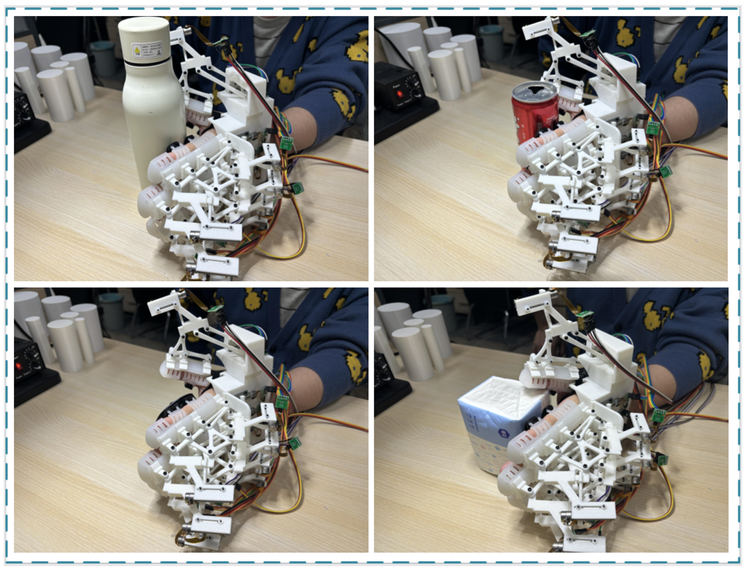
As shown in Figure 24, we conducted a grasping experiment involving daily necessities to determine whether the robot can help rehabilitated patients carry out normal grasping training for such items. In this experiment, in order to simulate the motion control method of the robot’s internal drive motor, the commodity is designed to be approximately circular shape.The robot is capable of grasping a variety of round objects (such as water cups and cans), as well as nearly round objects (such as tissue boxes and mice).

4. Discussion

Trajectory matching: The trajectory matching experiment demonstrates that positional deviations across all markers were maintained below 4 mm when grasping objects with diameters of 20–70 mm. This confirmed the robot’s capacity to emulate normal hand kinematics for rehabilitation assistance. These results validate the system’s operational efficacy and adaptive performance in therapeutic applications. Most of the rehabilitation robots shown in Table 10 have only 1 DoF for a single finger, which limits their adaptability to different grasping targets and hand sizes. Our robot system can plan out multiple motion trajectories to cope with different scenarios. Notably, an inverse correlation was observed between object diameter and trajectory deviation as follows: as the grasped object diameter increased from 20 mm to 70 mm, the mean error between the patient’s rehabilitative hand trajectory and healthy reference trajectory decreased from 14% to 4%. In addition to errors arising from linkage manufacturing tolerances and assembly clearances, the grasping of small-diameter objects induces amplified kinematic displacements, consequently inducing pronounced deformation in soft materials that synergistically exacerbates system errors. While implementing force/position feedback compensation could mitigate these control inaccuracies, the current open-loop control architecture requires further refinement to address such nonlinear error propagation mechanisms. Furthermore, the force sensor integration methodology necessitates the systematic evaluation of human–robot interaction impacts. Externally mounted sensors carry the risk of kinematic interference from unintended contact with structural linkages or skin. The embedded sensor needs to take into account the influences on the processing technology and deformation properties of soft materials.
Fingertip output force: The fingertip force output exhibits near-linear augmentation for 12 s before stabilizing. Rehabilitation robots are custom-engineered based on anthropometric finger dimensions, resulting in force differentials across fingertips. This variation is exemplified by the little finger (minimum output: 5 N) and thumb (maximum output: 7 N). Notably, all fingertips exhibit synchronized force modulation profiles, demonstrating the system’s capacity for coordinated multi-finger rehabilitation training aligned with biomechanical characteristics to address therapeutic objectives. Following extensive experimental validation, the fingertip output force maintains minimal variation (±0.5 N), demonstrating the rehabilitation robot’s dynamic consistency and operational stability across repetitive motion cycles.
Grasping ability of daily necessities: The developed rigid–soft coupling hand rehabilitation robot demonstrates effective adaptive grasping capabilities for various daily necessities. The system achieves trajectory congruence with prescribed reference trajectories when manipulating standard cylindrical objects. Notably, geometric cylindrical approximations of polygonal objects demonstrate non-negligible trajectory deviation between actual and desired grasping paths, confirming significant shape-dependent trajectory variations. This necessitates the implementation of shape-specific trajectory optimization protocols for polygonal objects. Furthermore, object deformation introduces additional trajectory perturbations.For example, when grasping a tissue box, we need to reduce the desired grasp diameter to increase the deformation of the tissue box. Thus, more pressure is obtained to increase the friction force and then pick up the tissue box.
Grasping adaptability: The rigid–soft coupling rehabilitation robotic system demonstrates sub-120-second computational time in deriving optimized motion control parameters for target grasping trajectories while maintaining ±4 mm errors, validating its multi-trajectory adaptive capabilities. The robot is designed according to standardized hand size and right-handed specifications. By making symmetric changes to the structure and trajectory of right-handed, a left-handed rehabilitation robot and training trajectory can be made. The soft material has a certain shapable variable as a redundant space to accommodate the patient in the dimensional space near the standardized hand shape. However, in clinical treatment, the robot needs to adapt to hand size changes at larger scales, such as the elderly, children, women, etc. Multiple crowd-standard size robots can be made to cope with different patient hand shapes. However, this can result in higher costs and waste of resources, as prevalence rates vary greatly among different populations. The rigid linkage mechanism can be designed as a telescopic structure for larger scale adjustment to improve patient adaptability. Machine learning algorithms facilitate the rapid dimensional optimization of linkage configurations, while additive manufacturing enables the rapid fabrication of patient-specific soft elements for subsequent modular assembly to satisfy individualized rehabilitation demands.
Mass production and commercialization: Current commercial rehabilitation robots usually come in the form of flexible wearable gloves with multiple built-in sensors for detecting the training process. Our robot is lightweight and easy to carry. It has multiple degrees of freedom, multiple trajectories, simple control, and multi-size adaptability. In the case of only bending sensors, the hand motion trajectory suitable for the patient can be generated in a short time, which reduces the complexity of the robot control system and design. This has certain advantages in terms of cost. For mass production and commercialization, the following three critical development vectors require prioritization:
  • Manufacturing process optimization: Transition from additive manufacturing and single-cavity injection molding to automated mass production techniques for linkage and soft component fabrication, targeting cycle time reduction.
  • Durability enhancement. Durability testing of the robot is required to improve the materials and processes according to the corresponding safety standards. Higher requirements are put forward for soft materials to ensure safety and durability.
  • Anthropometric customization: Manufacture products of different sizes for patients to choose from. It is improved to a retractable linkage mechanism, which can be customized and adjusted according to the patient’s hand size. Consider the development of feedback control schemes based on EMG sensing. AI technology is introduced to capture the intention of the patient so that the patient can actively control the actions of the robot.

5. Conclusions

This study presents the development of a rigid–soft coupled hand function rehabilitation robotic system designed to assist patients with impaired hand motor function. The system integrates the structural rigidity and kinematic precision of rigid linkages with the compliance and adaptability of soft components. The robotic platform demonstrates poly-trajectory planning capabilities. The robot can plan different trajectories to adapt to the requirements of a variety of people. The mechanism with 3 DoF can provide higher adaptability to imitate the trajectory of the human hand.
This study has limitations that need to be noted. Firstly, the trajectory planning of the robot belongs to the off-line planning method. No effective interaction with the patient was possible during training. Secondly, the link length of the robot is fixed, which has high adaptability only for some people. Third, the large size of the robot makes it difficult to carry. Fourth, there is a lack of long-term testing on the robot to detect its durability. In future research on rehabilitation robots, the following aspects may become the focus: Based on AI-driven online trajectory planning technology, the patient’s intention can be actively recognized by adding feedback sensors (force sensing, electromyography, etc.). Developing variable-sized rehabilitation robots and combining machine learning techniques to optimize their dimensions. Designing lightweight multi-degree of freedom robots, meeting a variety of trajectory planning requirements based on the implementation of portable machines.

Author Contributions

Conceptualization, R.Z.; Methodology, R.Z.; Software, R.Z. and Y.W.; Validation, R.Z., Y.W. and J.Y.; Formal analysis, R.Z.; Investigation, R.Z.; Supervision, M.N.; Project administration, M.N. All authors have read and agreed to the published version of the manuscript.

Funding

This work was supported by the Pilot Technology Pre-Research Program of Wuxi Industrial Innovation Research Institute (XD24001).

Data Availability Statement

All data supporting the findings of this study are available within the article. Any additional requests for information can be directed and will be fulfilled by the corresponding author. Source data are provided within this study.

Acknowledgments

We thank the Jiangsu Vocational College of Information Technology, Jiangsu Key Laboratory of Advanced Food Manufacturing Equipment and Technology, School of Intelligent Manufacturing, Jiangnan University and our participants for their contributions to this work.

Conflicts of Interest

The authors declare that they have no known competing financial interest or personal relationships that could have appeared to influence the work reported in this design.

Abbreviations

The following abbreviations are used in this manuscript:
DoFDegree of Freedom
TPUThermoplastic Polyurethane
SMPShape Memory Polymer
IABCImproved Artificial Bee Colony
ABCArtificial Bee Colony
MMMotion Matching
GAGenetic Algorithm
CGConvergence Generation

Appendix A

Table A1. Stand test functions.
FunctionDimensionalityRangeMinimum Value
f 1 ( x ) = i = 1 n ( j = 1 i x j ) 2 30[−100, 100]0
f 2 ( x ) = i = 1 n ( x i + 0.5 ) 2 30[−100, 100]0
f 3 ( x ) = i = 1 n i x i 4 + r a n d [ 0 , 1 ) 30[−1.28, 1.28]0
f 4 ( x ) = i = 1 n ( x i 2 10 c o s ( 2 π x i ) + 10 ) 30[−5.12, 5.12]0
f 5 ( x ) = 1 4000 i = 1 n x i 2 i = 1 n ( x i i ) + 1 30[−600, 600]0
f 6 ( x ) = 4 x i 2 2.1 x 1 4 + 1 3 x 1 6 + x 1 x 2 4 x 2 2 + 4 x 2 4 30[−5, 5]−1
f 7 ( x ) = ( x 2 5.1 4 π 2 x 1 2 + 5 π x 1 + 6 ) 2 + 10 ( 1 1 8 π ) c o s x 1 + 10 30[−5, 5]0.3
f 8 ( x ) = i = 1 4 c i e x p ( j = 1 3 a i j ( x j p i j ) 2 ) 30[1, 3]−3

References

  1. Pollock, A.; Farmer, S.E.; Brady, M.C.; Langhorne, P.; Mead, G.E.; Mehrholz, J.; Van Wijck, F. Interventions for improving upper limb function after stroke. Cochrane Database Syst. Rev. 2014, 2014, CD010820. [Google Scholar] [CrossRef]
  2. Buma, F.; Kwakkel, G.; Ramsey, N. Understanding upper limb recovery after stroke. Restor. Neurol. Neurosci. 2013, 31, 707–722. [Google Scholar] [CrossRef] [PubMed]
  3. Hunter, S.; Crome, P. Hand function and stroke. Rev. Clin. Gerontol. 2002, 12, 68–81. [Google Scholar] [CrossRef]
  4. Lum, P.S.; Godfrey, S.B.; Brokaw, E.B.; Holley, R.J.; Nichols, D. Robotic approaches for rehabilitation of hand function after stroke. Am. J. Phys. Med. Rehabil. 2012, 91, S242–S254. [Google Scholar] [CrossRef]
  5. Park, J.H. Effect of robot-assisted hand rehabilitation on hand function in chronic stroke patients. J. Korea Robot. Soc. 2013, 8, 273–282. [Google Scholar] [CrossRef]
  6. Schabowsky, C.N.; Godfrey, S.B.; Holley, R.J.; Lum, P.S. Development and pilot testing of HEXORR: Hand EXOskeleton rehabilitation robot. J. Neuroeng. Rehabil. 2010, 7, 1–16. [Google Scholar] [CrossRef]
  7. Hesse, S.; Mehrholz, J.; Werner, C. Robot-assisted upper and lower limb rehabilitation after stroke: Walking and arm/hand function. Dtsch. Ärzteblatt Int. 2008, 105, 330. [Google Scholar]
  8. Yue, Z.; Zhang, X.; Wang, J. Hand rehabilitation robotics on poststroke motor recovery. Behav. Neurol. 2017, 2017, 3908135. [Google Scholar] [CrossRef]
  9. Cheng, H.; Huang, R.; Qiu, J. A survey of rehabilitation robot and its clinical applications. Robot 2021, 43, 606–619. [Google Scholar]
  10. Nelson, C.A.; Nouaille, L.; Poisson, G. A redundant rehabilitation robot with a variable stiffness mechanism. Mech. Mach. Theory 2020, 150, 103862. [Google Scholar] [CrossRef]
  11. Marconi, D.; Baldoni, A.; McKinney, Z.; Cempini, M.; Crea, S.; Vitiello, N. A novel hand exoskeleton with series elastic actuation for modulated torque transfer. Mechatronics 2019, 61, 69–82. [Google Scholar]
  12. Chen, Z.; Zhan, F.; Jiang, J.; Wu, D.; Sun, J. A review on soft hand rehabilitation robot. Recent Patents Eng. 2023, 17, 12–36. [Google Scholar] [CrossRef]
  13. Chu, C.Y.; Patterson, R.M. Soft robotic devices for hand rehabilitation and assistance: A narrative review. J. Neuroeng. Rehabil. 2018, 15, 1–14. [Google Scholar]
  14. Meng, N.; Kun, W.; Mingxin, L.; Ke, Y.; Zhi, W. Design, analysis and experiment of finger soft actuator with nested structure for rehabilitation training. Adv. Mech. Eng. 2020, 12, 1687814020971538. [Google Scholar] [CrossRef]
  15. Lin, L.; Zhang, F.; Yang, L.; Fu, Y. Design and modeling of a hybrid soft-rigid hand exoskeleton for poststroke rehabilitation. Int. J. Mech. Sci. 2021, 212, 106831. [Google Scholar] [CrossRef]
  16. Rose, C.G.; O’Malley, M.K. Hybrid rigid-soft hand exoskeleton to assist functional dexterity. IEEE Robot. Autom. Lett. 2018, 4, 73–80. [Google Scholar] [CrossRef]
  17. Liu, C.; Lu, J.; Yang, H.; Guo, K. Current state of robotics in hand rehabilitation after stroke: A systematic review. Appl. Sci. 2022, 12, 4540. [Google Scholar] [CrossRef]
  18. Aggogeri, F.; Mikolajczyk, T.; O’Kane, J. Robotics for rehabilitation of hand movement in stroke survivors. Adv. Mech. Eng. 2019, 11, 1687814019841921. [Google Scholar] [CrossRef]
  19. Bianchi, M.; Fanelli, F.; Meli, E.; Ridolfi, A.; Vannetti, F.; Bianchini, M.; Allotta, B. Optimization-based scaling procedure for the design of fully portable hand exoskeletons. Meccanica 2018, 53, 3157–3175. [Google Scholar] [CrossRef]
  20. Lai, J.; Song, A. Design and Characterization of a Novel Compact Hand Exoskeleton Robot for Telerehabilitation and Muscle Spasticity Assessment. IEEE/ASME Trans. Mechatron. 2024, 29, 2416–2427. [Google Scholar] [CrossRef]
  21. Wang, S.; Dong, M.; Jiao, R.; Sun, S.; Li, J. Design and Analysis of Four-Finger Three-Joint Underactuated Hand Rehabilitation Mechanism. In Intelligent Robotics and Applications; Yang, H., Liu, H., Zou, J., Yin, Z., Liu, L., Yang, G., Ouyang, X., Wang, Z., Eds.; Springer: Singapore, 2023; Volume 14274, pp. 25–37. [Google Scholar]
  22. Zou, H.; Wu, Q.; Yang, L.; Zhu, Y.; Wu, H. Design and EMG-EEG Fusion-Based Admittance Control of a Hand Exoskeleton With Series Elastic Actuators. IEEE Trans. Med. Robot. Bionics 2025, 7, 347–358. [Google Scholar] [CrossRef]
  23. Cappello, L.; Meyer, J.T.; Galloway, K.C.; Peisner, J.D.; Granberry, R.; Wagner, D.A.; Engelhardt, S.; Paganoni, S.; Walsh, C.J. Assisting hand function after spinal cord injury with a fabric-based soft robotic glove. J. Neuroeng. Rehabil. 2018, 15, 1–10. [Google Scholar] [CrossRef]
  24. Duanmu, D.; Li, X.; Huang, W.; Hu, Y. Soft Finger Rehabilitation Exoskeleton of Biomimetic Dragonfly Abdominal Ventral Muscles: Center Tendon Pneumatic Bellows Actuator. Biomimetics 2023, 8, 614. [Google Scholar] [CrossRef]
  25. Shi, X.; Yang, C.; Lee, P.C.; Xie, D.; Ye, Z.; Li, Z.; Tong, R.K. An interactive soft robotic hand-task training system with wireless task boards and daily objects on post-stroke rehabilitation. Wearable Technol. 2025, 6, e4. [Google Scholar] [CrossRef] [PubMed]
  26. Rho, E.; Lee, H.; Lee, Y.; Lee, K.D.; Mun, J.; Kim, M.; Kim, D.; Park, H.S.; Jo, S. Multiple Hand Posture Rehabilitation System Using Vision-Based Intention Detection and Soft-Robotic Glove. IEEE Trans. Ind. Inform. 2024, 20, 6499–6509. [Google Scholar] [CrossRef]
  27. Ying, C.; Qingyun, M.; Hongliu, Y. Research progress on the development of hand rehabilitation robot. Beijing Biomed. Eng. 2018, 37, 650–656. [Google Scholar]
  28. Yap, H.K.; Lim, J.H.; Nasrallah, F.; Goh, J.C.; Yeow, R.C. A soft exoskeleton for hand assistive and rehabilitation application using pneumatic actuators with variable stiffness. In Proceedings of the 2015 IEEE International Conference on Robotics and Automation (ICRA), Seattle, WA, USA, 26–30 May 2015; pp. 4967–4972. [Google Scholar]
  29. Haghshenas-Jaryani, M.; Carrigan, W.; Nothnagle, C.; Wijesundara, M.B. Sensorized soft robotic glove for continuous passive motion therapy. In Proceedings of the 2016 6th IEEE International Conference on Biomedical Robotics and Biomechatronics (BioRob), Singapore, 26–29 June 2016; pp. 815–820. [Google Scholar]
  30. Liang, R.; Zhang, Q.; He, B.; Li, L. Visual Representation of the Compactness of a Stephenson-II Six-Bar Linkage Exoskeleton Using Solution Region Synthesis Theory. IEEE Robot. Autom. Lett. 2024, 9, 4415–4422. [Google Scholar] [CrossRef]
  31. Moreno-SanJuan, V.; Cisnal, A.; Fraile, J.C.; Pérez-Turiel, J.; de-la Fuente, E. Design and characterization of a lightweight underactuated RACA hand exoskeleton for neurorehabilitation. Robot. Auton. Syst. 2021, 143, 103828. [Google Scholar] [CrossRef]
  32. Kim, H.M.; Kim, G.S. Development of a finger-rehabilitation robot for fingers’ flexibility rehabilitation exercise. Int. J. Precis. Eng. Manuf. 2013, 14, 535–541. [Google Scholar] [CrossRef]
  33. Guo, K.; Lu, J.; Liu, C.; Yang, H. Development, Research, Optimization and Experiment of Exoskeleton Robot for Hand Rehabilitation Training. Appl. Sci. 2022, 12, 10580. [Google Scholar] [CrossRef]
  34. Zhang, X.; Rong, X.; Luo, H. Optimizing lower limb rehabilitation: The intersection of machine learning and rehabilitative robotics. Front. Rehabil. Sci. 2024, 5, 1246773. [Google Scholar] [CrossRef]
  35. Jamwal, P.K.; Hussain, S.; Xie, S.Q. Three-stage design analysis and multicriteria optimization of a parallel ankle rehabilitation robot using genetic algorithm. IEEE Trans. Autom. Sci. Eng. 2014, 12, 1433–1446. [Google Scholar] [CrossRef]
  36. Li, G.; Cheng, L.; Sun, N. Design, manipulability analysis and optimization of an index finger exoskeleton for stroke rehabilitation. Mech. Mach. Theory 2022, 167, 104526. [Google Scholar] [CrossRef]
  37. Zi, B.; Yin, G.; Zhang, D. Design and optimization of a hybrid-driven waist rehabilitation robot. Sensors 2016, 16, 2121. [Google Scholar] [CrossRef]
  38. Shen, Q.; Lee, W.T.; Russell, K.; Sodhi, R.S. On motion generation of Watt I mechanisms for mechanical finger design. Trans. Can. Soc. Mech. Eng. 2008, 32, 411–422. [Google Scholar] [CrossRef]
  39. Zhang, Z.; Zhang, Y.; Ning, M.; Zhou, Z.; Wu, Z.; Zhao, J.; Li, X.; Liu, W. One-DOF six-bar space gripper with multiple operation modes and force adaptability. Aerosp. Sci. Technol. 2022, 123, 107485. [Google Scholar] [CrossRef]
  40. Liang, B.; Tian, Y.; Zhang, W. A Straight Parallel Grasping and Self-Adaptive Gripper with Differential and Watt Linkages. In Proceedings of the 2023 International Conference on Advanced Robotics and Mechatronics (ICARM), Sanya, China, 8–10 July 2023; pp. 624–629. [Google Scholar]
  41. Rus, D.; Tolley, M.T. Design, fabrication and control of soft robots. Nature 2015, 521, 467–475. [Google Scholar] [CrossRef] [PubMed]
  42. Cianchetti, M.; Laschi, C.; Menciassi, A.; Dario, P. Biomedical applications of soft robotics. Nat. Rev. Mater. 2018, 3, 143–153. [Google Scholar] [CrossRef]
  43. Shepherd, R.F.; Ilievski, F.; Choi, W.; Morin, S.A.; Stokes, A.A.; Mazzeo, A.D.; Chen, X.; Wang, M.; Whitesides, G.M. Multigait soft robot. Proc. Natl. Acad. Sci. USA 2011, 108, 20400–20403. [Google Scholar] [CrossRef]
Figure 1. Rigid–soft coupling hand function rehabilitation robot. (a) Single-finger rehabilitation robot structure. (b) Overall of the rehabilitation robot.
Machines 13 00311 g001
Figure 2. Schematic diagram of the single-finger rigid linkage mechanism. (a) Schematic of the overall mechanism. (b) Diagram of the crank slider.
Machines 13 00311 g002
Figure 3. Structural parameters and annotations of the soft part.
Machines 13 00311 g003
Figure 4. Acquisition system of hand tracking.
Machines 13 00311 g004
Figure 5. Average length of the index finger at different grasping sizes.
Machines 13 00311 g005
Figure 6. Length variance of the index finger at different grasping sizes.
Machines 13 00311 g006
Figure 7. Index-finger motion trajectories under different grasp sizes.
Machines 13 00311 g007
Figure 8. Matching analysis of the mechanism and hand motion. (a) The trajectory of the finger movement. (b) The trajectory of the links’ movement, where the cycles are joints of finger.
Machines 13 00311 g008
Figure 9. Motion matching between the planned trajectory and the target trajectory.
Machines 13 00311 g009
Figure 10. Rigid link parts and dimensions of the robot.
Machines 13 00311 g010
Figure 11. Simulation effect diagram of different hand cavity thickness T 1 . (a)–(c) are screenshots of the simulation sequence when the soft component is under pressure.
Machines 13 00311 g011
Figure 12. Simulation effect diagram of different sensor cavity thickness T 2 . (a)–(c) are screenshots of the simulation sequence when the soft component is under pressure.
Machines 13 00311 g012
Figure 13. Structure of the sensor cladding surface.
Machines 13 00311 g013
Figure 14. Sequence diagram of the soft structure simulation. (a)–(h) are screenshots of the simulation sequence when the soft component is under pressure.
Machines 13 00311 g014
Figure 15. Motion trajectory of the soft structure simulation. Lines (a)–(h) are the position change sequence of the soft component during the simulation.
Machines 13 00311 g015
Figure 16. Trajectory of the linkage structure during the grasp with a 40 mm diameter. The yellow part is the initial position, and the purple part is the final position.
Machines 13 00311 g016
Figure 17. Motion trajectory simulation error of the marker.
Machines 13 00311 g017
Figure 18. Rigid–soft coupling hand function rehabilitation robot system. (a) Flex one-way bending sensor. (b) Overall schematic.
Machines 13 00311 g018
Figure 19. Trajectory matching experiments when grasping different diameters.
Machines 13 00311 g019
Figure 20. Trajectory matching error diagram of the principle prototype.
Machines 13 00311 g020
Figure 21. Bending angle error of soft components.
Machines 13 00311 g021
Figure 22. Fingertip output force detection for the rehabilitation robot.
Machines 13 00311 g022
Figure 23. Fingertip pressure data of the rehabilitation robot.
Machines 13 00311 g023
Figure 24. Grasping test of daily necessities for the robot.
Machines 13 00311 g024
Table 1. Soft material comparison for rehabilitation robotics.
Comparison CriteriaSilicone Rubber (Ecoflex 10)Thermoplastic Polyurethane (TPU)Shape Memory Polymer (SMP)
BiocompatibilityMedical certificationRequires post-processingComposition-dependent
HardnessSoftRigidProgrammable
Elongation at Break>1000%300–600%<200%
Fatigue Resistance>1 million cycles∼100k cycles before crackingDecaying after >100 cycles
ManufacturingCastinginjection moldingThermal/UV curing
Temperature Stability−50 °C to 200 °C−40 °C to 120 °CEnvironment-sensitive
SafetyOptimalRisk of pressure injuriesThermal activation may cause discomfort
LifespanLongestModerateShortest
ApplicationsRehabilitation glovesExoskeleton framesShape-changing tools
Table 2. Comparison of performance parameters of Ecoflex series liquid silica gel.
Ecoflex 5Ecoflex 50Ecoflex 30Ecoflex 33AFEcoflex 20Ecoflex 10
Mixing viscosity (CPS)13,000800030003000300014,000
Specific volume25.825.926.026.026.026.6
Curing time (h)0.1234444
Shore hardness55030332010
Tensile strength (psi)350315200200160120
Tear strength (pli)755038383022
Shrinkage (in./in)<0.001<0.001<0.001<0.001<0.001<0.001
Elongation at break (%)1000980900900845800
Table 3. Soft part structure parameters.
ParametersNames
LTotal length of soft part
D 1 Length of soft and rigid joint
D 2 Length of seating surface
D 3 Length of interval
HWidth of sensor cavity
RRadius of hand cavity
T 1 Thickness of hand cavity
T 2 Thickness of sensor cavity
T 3 Thickness of sensor cavity bottom
Table 4. Theoretical length of each segment of the index finger for track acquisition.
Proximal KnuckleMiddle KnuckleDistal Knuckle
42.5 mm23 mm22 mm
Table 5. Fitting equation of each grasp.
DiameterEquation x 4 x 3 x 2 x x 0
20 mm y 1 000.1452−8.652100.8
y 2 000.0321−1.929−21.53
y 3 000.0177−1.061−56.97
30 mm y 1 0.0007682−0.099854.4884−105.3808.8
y 2 0.00002659−0.0035060.1795−3.9721.21
y 3 0.000005900.000810.04424−0.956−66.52
40 mm y 1 0.72060.15250.3647−5.073−15.85
y 2 2.6234.2633.4139.031−35.14
y 3 7.2569.7443.1138.953−55.86
50 mm y 1 0.14330.08951−0.33370.8203−4.745
y 2 0.62421.9922.9657.08−20.19
y 3 3.4827.1343.9498.967−38.69
60 mm y 1 000.24561.159−5.585
y 2 002.4757.126−21.11
y 3 005.40114.06−38.41
70 mm y 1 000.26270.6765−2.654
y 2 001.4216.31−13.4
y 3 003.86613.04−25.57
Table 6. Range of links.
LinksABBEDEADCDDGFG
Ranges (mm)20–4020–4520–4035–455–1235–4530–45
LinksCFACEGGHFHIJ
Ranges (mm)20–3535–4520–3525–3520–3560–75
Table 7. Comparison of the results of different algorithms.
IABCABCGA
CGTime (s)ValuesCGTime (s)ValuesCGTime (s)Values
f 1 513.2437.41  ×   10 12 533.5378.13  ×   10 14 564.1788.53  ×   10 14
f 2 433.5646.33  ×   10 13 494.5687.22  ×   10 14 595.5146.13  ×   10 14
f 3 413.7455.41  ×   10 15 514.7435.74  ×   10 14 525.1576.11  ×   10 14
f 4 573.4136.12  ×   10 14 614.8158.53  ×   10 14 635.8117.59  ×   10 14
f 5 443.3486.13  ×   10 14 535.1117.13  ×   10 14 586.6346.44  ×   10 14
f 6 513.411−0.99914555.933−0.99564597.128−0.96414
f 7 483.8750.30001616.1450.29996636.7810.30003
f 8 363.136−2.9991556.537−2.9975607.461−2.9413
Table 8. Soft part structure parameters.
ParametersL D 1 D 2 D 3 HR T 1 T 2 T 3
Ranges (mm)80–12010332131–31–32
Table 9. Initial parameter range and optimization results for 40 mm motion planning.
Parameters a 1 a 2 a 3 b 1 b 2 b 3 c 1 c 2 c 3
Ranges (mm)[−200, 200]
Results (mm)186.9676.62−107124.21−104.2591.2140.41113.6623.55
Table 10. The comparison of rehabilitation robots.
RobotsTypeNumber of Actuator/FingerFive Fingers TrainingSingle Finger TrainingMultiple TrajectoriesSize AdaptabilityDaily Necessities Grasping
[22]Rigid1-Yes--Yes
[21]Rigid1Yes----
[24]Soft1YesYes-YesYes
[26]Soft1YesYes-YesYes
[31]Rigid–Soft3YesYesYes-Yes
[32]Rigid–Soft1YesYes-Yes-
oursRigid–Soft3YesYesYesYesYes
Disclaimer/Publisher’s Note: The statements, opinions and data contained in all publications are solely those of the individual author(s) and contributor(s) and not of MDPI and/or the editor(s). MDPI and/or the editor(s) disclaim responsibility for any injury to people or property resulting from any ideas, methods, instructions or products referred to in the content.