Article

Analysis of the Fracture and the Repair of the Screw Spindle of a Friction Screw Press

by
Rade Vasiljević
1,* and
Dragan Pantelić
2
1
School of Railroad Transport, Academy of Technical and Art Applied Studies, 11000 Belgrade, Serbia
2
Auto-Valve J-S Company, 31000 Užice, Serbia
*
Author to whom correspondence should be addressed.
Machines 2025, 13(4), 309; https://doi.org/10.3390/machines13040309
Submission received: 25 February 2025 / Revised: 22 March 2025 / Accepted: 26 March 2025 / Published: 10 April 2025
(This article belongs to the Section Machines Testing and Maintenance)

Abstract

The drive mechanism of a friction screw press consists of a screw transmission, a friction transmission and a belt transmission. Improper maintenance and axial misalignment of the screw spindle and the press are the main possible causes of screw spindle failure. The causes of the screw spindle fracture are investigated in the first part of this paper. A visual examination of the screw spindle is carried out in the first step. In the second step, the chemical composition and mechanical properties of the material from which the screw spindle of the drive mechanism is made are experimentally examined, and a metallographic examination of the fracture surfaces on the screw spindle is carried out using an electronic microscope. In the second part of this paper, the effects of screw spindle disturbances on the fracture are analyzed by applying the finite element method. The third part of this paper shows how the problem of repairing the damaged screw spindle of the drive mechanism of the friction screw press is solved. Firstly, the repair solution is described. Then, a safety check of the welded joint is presented. The final part refers to the techno-economic justification of the performed repair of the screw spindle. The obtained research results are important because the same problems or similar problems could appear in machine elements of various types of machine tools.

1. Introduction

During the exploitation of machine parts (e.g., gears, shafts, screw spindles, etc.), and due to various reasons, their surfaces wear and eventually fracture. Fractures began to be intensively researched after the disasters and fractures of some large structures in the first half of the 20th century [1]. The importance of fracture research is shown in [2,3,4,5,6]. On the other hand, refs. [7,8,9] consider the justification of repairing the broken parts.
This paper investigates the fracture of the screw spindle of a friction screw press (FSP). These presses are widely spread deformation processing machines used to perform forging and extrusion operations. An electric motor and a transmission mechanism in the form of a mechanical-friction transmission are used to drive screw friction presses. During exploitation, they are exposed to static and dynamic loads. The form of the dynamic load is load because the deformation is realized by the kinetic energy of the rotational lowering of the working masses by means of the screw working mechanism. In other words, friction presses work with the stroke character of their action, whereby the electric drive of the press is automatically switched off before the stroke so that it does not receive additional loads at the moment of the stroke. A diagram of the dependence of the forging force and the working stroke of the presser is given in [10].
In the production facility of the company Auto-valve Užice, Serbia [11], valve forging is performed on friction screw presses. After 72,000 h of exploitation of the friction screw press type FSP-160 (Figure 1), during a period of 15 years, the screw spindle of the drive mechanism fractured (Figure 2), which caused the press to fail. Considering that in the production plant of the company Auto-valve, there are seven presses from the family of friction screw presses, on the one hand, and considering that these presses play an important role in the production program of the company, on the other hand, the investigation of the cause of the fracture of the screw spindle in the drive mechanism of the press is of particular importance.
The screw spindle failure occurred after normal press operation. After the FSP-160 had been exploited for more than fifteen years, in 2016, some defects were observed in the zone of the screw spindle end at the point of connection of the screw spindle with the presser by means of a conical pin (Figure 2).
According to the technical documentation and the brochure [12,13], the screw spindle was made of 50CrMo4 steel, the largest diameter was 162 mm, the length was 1405 mm, the mass was 192 kg and the number of revolutions was 70 min−1. The screw spindle was made by cutting.
In order to determine the causes of the screw spindle fatigue cracks at the point of the conical pin, which was used to connect the screw spindle to the presser, a visual examination, an experimental procedure (test of the chemical composition, microhardness and tensile properties) and a metallographic examination of the fracture surfaces on the screw spindle were carried out first. Then, the authors conducted an analysis of the stress state of the screw spindle in the drive mechanism. In the end, according to the adopted solution of the authors, the damaged screw spindle was repaired.
Despite the existence of modern machines, many companies do not have the financial means to purchase them. These challenges motivated the authors of this paper to investigate the cause of the fracture of the screw spindle of an FSP and the justification for the application of the repair of the broken screw spindle.
The conclusions provided by the results are aimed at improving the maintenance of friction screw press. The research results presented in this paper are important, because the same problems or similar problems may appear in the structures of different types of machine tools. More details on this problem are given in [14,15]. The paper [14] focused on the unintended failure that incurs high costs for repairs and production losses. Paper [15] presents possible methods and solutions to prevent collisions and collision damage to machine tool components. The focus of the considerations is the main spindle unit, which is one of the main components in the cutting process. The importance of repairing parts (e.g., shafts and gears) of the rolling mills can be particularly emphasized [16,17]. In [16], Cheng et al. analyzed the failure of Mill Rolls at China Steel Corporation. In paper [17], two methods are presented for repair welding of a total of eight gear shafts (toothed shafts) of service rollers in the “Topla valjaonica” rolling mill within Železara Smederevo.

2. Examination of the Cause of the Screw Spindle Fracture in the Drive Mechanism

The first main aim of this paper is to investigate the cause of the screw spindle fracture using two methods:
  • Visual examination;
  • Experimental test procedure.
Before the test of the screw spindle fracture, some similar tests were considered [18,19,20,21,22,23,24,25,26,27].

2.1. Visual Examination

After the failure of the screw spindle in the operation of the FSP-160 friction screw press, an analysis of its state was carried out. In the first step, in order to determine the state of the damaged screw spindle of the friction screw press type FSP-160, preliminary visual examinations were performed. In the second step, the test of the state of the screw spindle was carried out. A photographic representation of the faults is given in Figure 3.

2.2. Experimental Test Procedure

The experimental procedure of testing the screw spindle included the following:
  • Testing of the chemical composition and mechanical properties of the materials [21];
  • Metallographic examination of the fracture surfaces.

2.2.1. Test of the Chemical Composition and Mechanical Properties of the Materials

According to the manufacturer’s data [12], the screw spindle of the drive mechanism of the friction screw press is made of 50CrMo4 steel. The location of the fatigue fracture initiation is shown in Figure 4a. The samples for the analysis of the chemical composition and the preparation of test parts for testing the mechanical properties of the screw spindle were taken at the point of its fracture, from the points shown in Figure 4b.
The examination of the chemical composition was carried out using a SpektroLab M12 spectrometer [28]. The results of testing the chemical composition of the samples are presented in Table 1. The examination of the mechanical properties of the material was carried out using the Wilson VH1150 hardness tester [29]. The Vickers hardness is explicitly HV10 for the load of 10 kg. The hardness values were determined experimentally at different positions of the cut sample (Figure 4b). Based on the hardness values, the values of tensile characteristics of the material (tensile strength Rm and 0.2 proof stress R0.2) [30] were calculated for the same positions of the sample because it was not possible to make test samples for their examination in the area of the material failure due to fatigue (Equations (1) and (2)). The results of the testing and calculation of the mechanical properties of the screw spindle are presented in Table 2.
R m = 90.7 + 2.876 H V ,
R 0.2 = 99.8 + 3.734 H V .

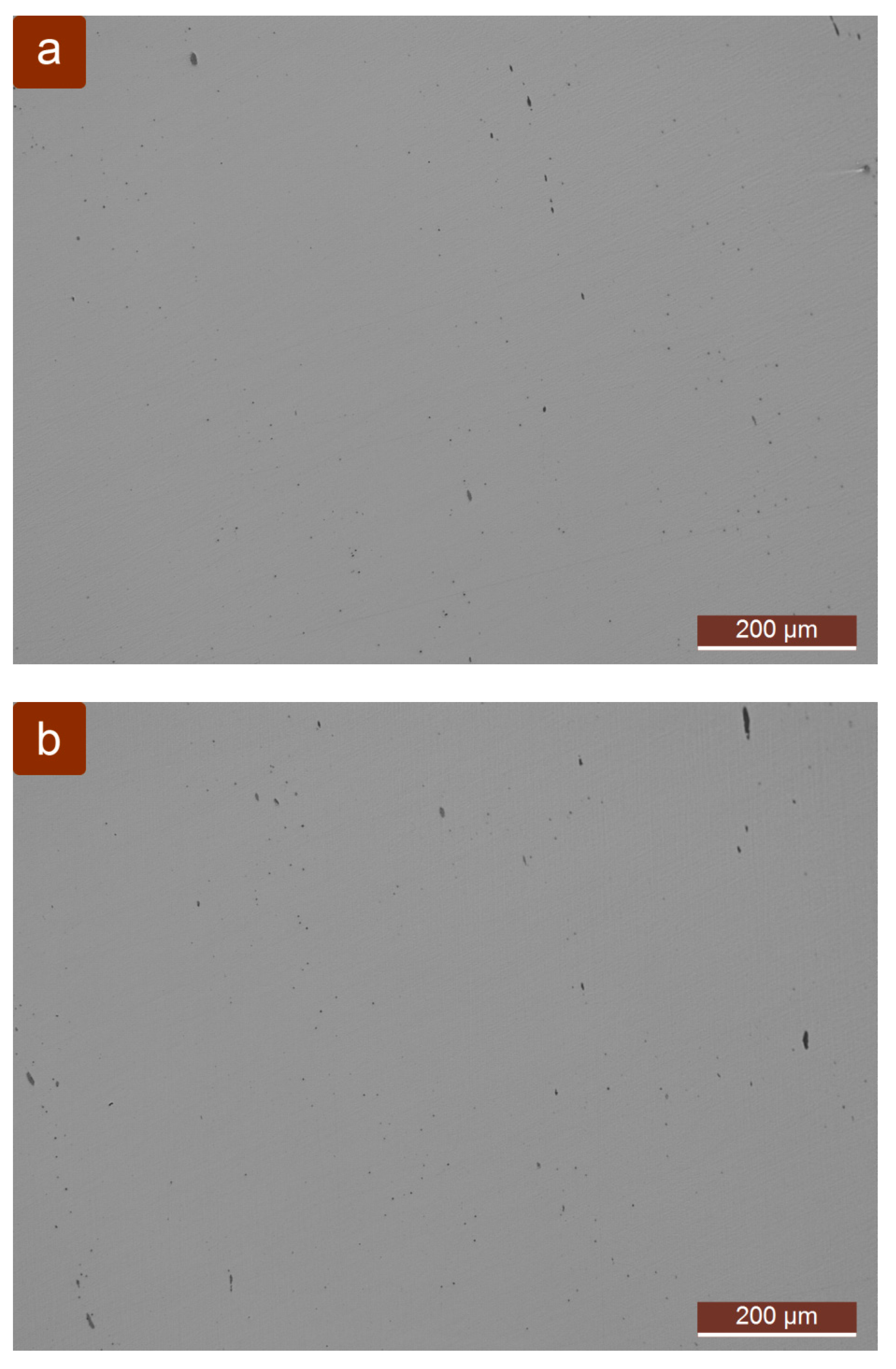
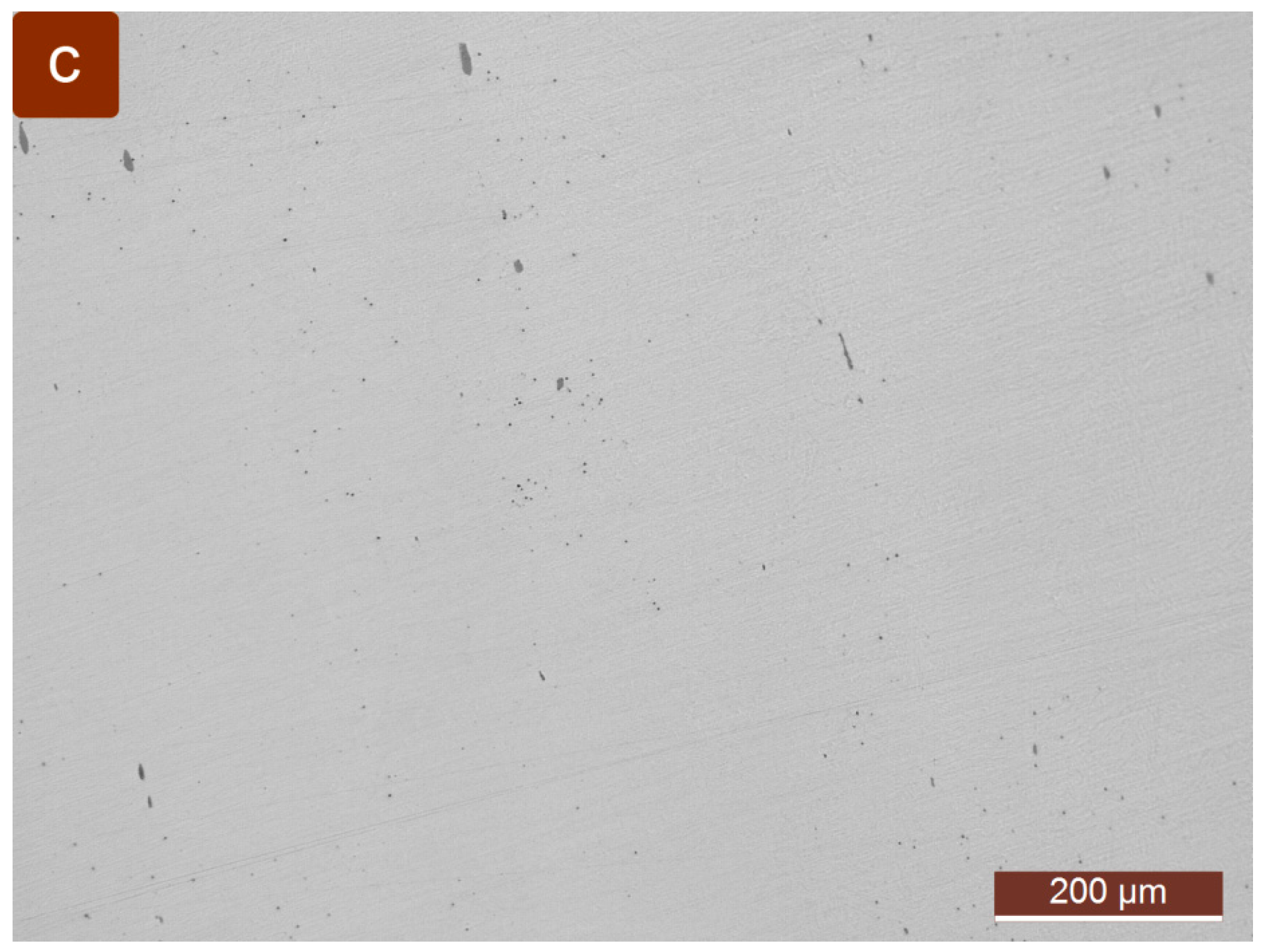
2.2.2. Metallographic Examination of the Fracture Surfaces

After a visual examination, in order to obtain as realistic a picture of the fracture surface on the screw spindle of the friction screw press drive as possible, stereoscopy was carried out. The metallographic examination was performed using a Leica DM4M microscope [32]. The results of these tests are as follows:
  • Magnified crack in the microstructure of the material in the grinding and polished state with non-metallic inclusions, in the fatigue zone (Figure 5) and the determined content of non-metallic inclusions (Table 3);
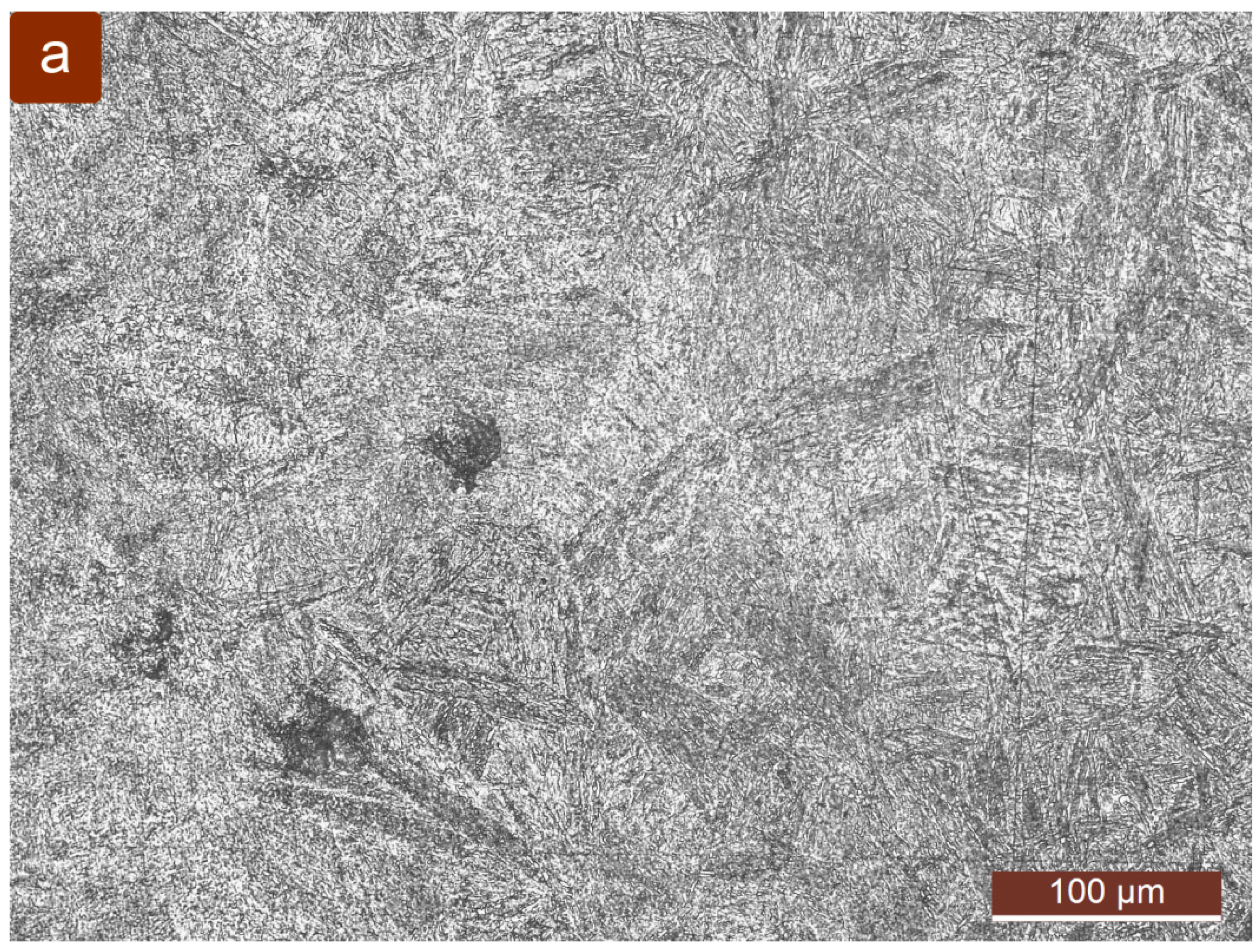
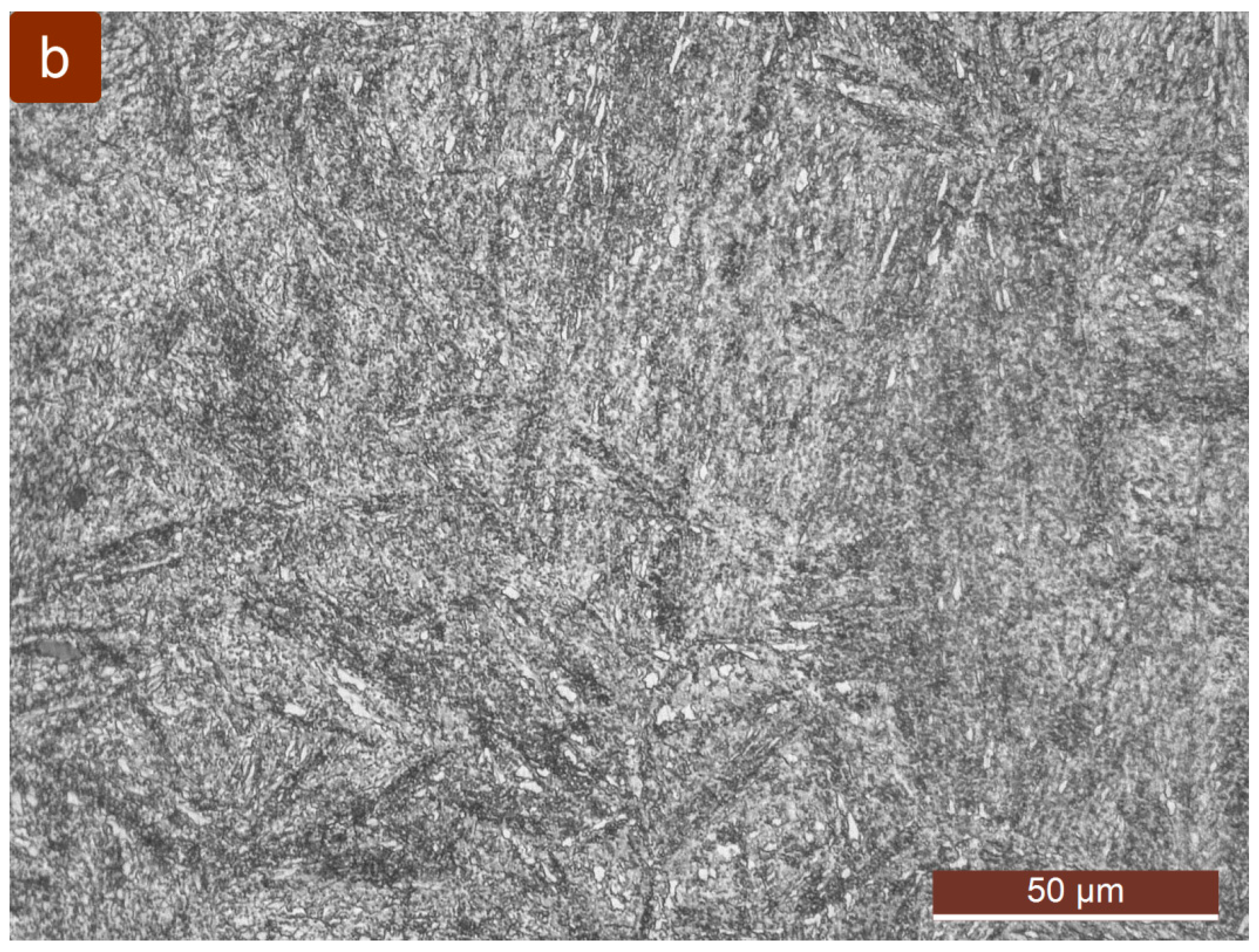
  • Magnified material microstructure in the grinding, polished and etching state with fractures in the plastic fracture zone (Figure 6).

2.2.3. Discussion of the Examination Results

The visual examination of the state of the damaged screw spindle of the press allowed a preliminary insight into the state of the screw spindle. The preliminary visual examination of the state of the damaged screw spindle of the press indicated the presence of serious faults (discontinuities), such as cracks, fractures and deformations on the surface of the screw spindle. Serious errors (discontinuities), such as cracks, fractures and deformations on the surface of the screw spindle, were roughly observed. These faults were concentrated at the bottom end of the screw spindle, which is connected to the presser by means of a conical pin (Figure 2).
The results of the chemical testing of the samples taken at the fracture point of the screw spindle showed that the chemical composition and the mechanical properties do not correspond to the quality of 50CrMo4 steel. The results of this sample analysis most closely match the 34CrNiMo6 steel type [31]. Also, the hardness of the material of the screw spindle at the point of fracture does not meet the requirements for 50CrMo4 steel; i.e., it is 229–230 HV. The mechanical hardness test results obtained are lower than the required value of 248–266 HV [12]. In other words, the obtained results are not within the limits recommended by the standard (see DIN EN 10083) for 50CrMo4 steel [31].
The measured hardness shows that there is no significant scatter and that it is uniform for all samples taken at the points marked in Figure 4b. The material has satisfactory purity, and there are no non-metallic inclusions that can cause the spindle to fracture (Figure 5 and Table 3). The microstructure is bainite–sorbite with retained austenite; see Refs. [33,34].
The external appearance of the fracture surface (Figure 3 and Figure 4) indicates that the fracture was caused due to the fatigue of the material in which some characteristic signs of tearing can be seen [1,2,3,4,5,6]. From Figure 4, it is possible to clearly see the initialization of the fracture fatigue. The fracture of the screw spindle started in the immediate vicinity of the opening for the pin. The experimental procedure of testing the chemical composition and the mechanical properties of the material showed that the fracture could have occurred due to a defect in the material. Also, this fact was confirmed by visual and metallographic examination of the fracture surface on the screw spindle.

3. Finite Element Analysis of the Stress State of the Screw Spindle

The second main aim of this paper is to investigate the cause of the screw spindle fracture by analyzing its stress state. The analysis of the stress state of the screw spindle of the press drive mechanism was performed using the finite element method [21,22,23,24,25,26,27]. ANSYS software [35,36] was used in the analysis.

3.1. ANSYS FEM Analysis

According to the technical documentation and the brochure [12,13], the support of the screw spindle is realized through a fixed nut, a friction bearing and an axial bearing (Figure 2).
After the structural analysis of the friction screw press, a 3D model of the screw spindle of the press drive mechanism was built (Figure 7a). The model of the screw spindle represents a discretized continuum using x-node tetrahedral elements. Based on the screw spindle model, an FE mesh model with 222,486 nodes and 55,065 elements was formed (Figure 7b). Accurate analysis of the contact stress between the screw spindle and the nut is a complex task as it involves a large number of contact elements. On the other hand, that is not the aim of this research. Since its version 15, ANSYS software has had a tool for simplified stress analysis of a threaded joint, so a detailed 3D model is not required. The contact of the power screw is adjusted quickly by entering the appropriate parameters and gives sufficiently accurate results. The contact surface between the screw spindle and the nut is set as a friction contact (Figure 8a), with a coefficient of friction μ = 0.15. Concretely, setting the contact parameters, i.e., geometric modification, for the 3D model of the power screw from Figure 7 is shown in Figure 8b.
Then, the boundary conditions, i.e., support zones and load transfer, were entered into the model (Figure 9).
The screw spindle of the press drive was analyzed for static loads. The variability of the pressing force is a source of variable loads, which leads to the appearance of dynamic interactions at the point of connection between the screw spindle and the presser.
As a result of the FE analysis, a uniaxial stress field was obtained, according to the maximum distortion energy (von Mises) hypothesis [21,35,37] (Figure 10). The ANSYS Workbench uses the von Mises criterion.
The safety factor SF of the screw spindle in the critical section in the zone fracture (at the point of the conical pin) is
S F = σ y σ e , max =   650.00 555.08 = 1.171 .
The fatigue analysis with the application of the FEM shows that the value of the fatigue safety factor at the critical point of the edge of the opening is 1.171 (Figure 11).

3.2. Discussion of the FEM Analysis Results

Based on the FEM results regarding the stress state of the screw spindle, the following conclusions can be made:
  • The stress concentration is highest in the connection zone between the bottom end of the screw spindle and the presser (at the point of the conical pin).
  • The stress state level in the screw spindle fraction zone is very high.
  • The maximum value of uniaxial stress is located in the fracture zone at the point of the conical pin (see (Figure 10)). The value of σe,max = 555.08 N/mm2 was read. This value was obtained at the maximum forging force (Fmax = 1600 kN).
  • The safety factor (Equation (3)) of the screw spindle at the critical point of the edge of the opening is greater than the minimum required SFmin = 1.00. However, the safety factor has a low value. It is recommended that for ductile materials, the degree of safety should have the lowest value SF = 1.30. Also, it is recommended that the safety factor should be within the limits for strict classic design SF = 1.30…1.50 [38].

4. Screw Spindle Repair

The third (final) goal of this paper is the repair of the screw spindle. In the first step, an insight into Refs. [39,40,41,42] on the problems of repairing broken machine parts was gained. Based on the results of the examination of the damaged screw spindle, on the one hand, and the safety check of the welded joint and the techno-economic analysis, on the other hand, it was decided to repair the observed faults (cracks, deformations and fractures) on the screw spindle.
Since there is serious damage to the end of the screw spindle that is attached to the presser, the conceptual solution for the damaged screw spindle is to repair it. The aim of repair of the broken screw spindle is to restore the lost working capacity of the screw spindle in a precisely defined sequence of operations, which should be consistently carried out.
In accordance with the defined problem and the conducted analysis of the state of the damaged screw spindle, the welding method which belongs to the group of thermal repair methods was chosen. The repair of the damaged screw spindle included the following main activities:
  • Elaboration of technical drawings;
  • Repair welding;
  • Checking the safety of the welded joint;
  • Techno-economic analysis of the repair.

4.1. Elaboration of Technical Drawings

The elaboration of technical drawings covered the following workshop drawings: the main healthy part of the screw spindle, the extension of the screw spindle and the repaired screw spindle. On the basis of this documentation, the repair of the screw spindle of the friction screw press FSP-160 [13] will be carried out.

4.2. Repair Welding

Repair welding of the screw spindle includes the following operations:
  • Machining of the main (healthy) part of the screw spindle (I): transverse machining by turning at the fracture point to a length of 1246.5 mm as well as boring and internal turning of a hole ø50 × 50 mm.
  • Machining of the screw spindle extension (II): transverse machining by turning to a diameter of ø120, longitudinal machining by turning a cylindrical surface ø120 × 158.5 mm, machining by turning a cylindrical surface ø50 × 50 mm and transverse machining by turning to a diameter of ø120 and a length of 158.5 mm.
  • Thermal treatment of the screw spindle extension (2) [12].
  • V-grooving (see Figure 12). The welding surfaces (cones of the groove) on the healthy part of the screw spindle (I) and its extension (II) are formed by a mechanical process. Machining of the cone of the groove was performed by turning and grinding.
  • Bonding the healthy part of the screw spindle (I) with the extension of the screw spindle (II), so that the fit has a small lap (ø50H7/n7).
  • Joining the healthy part of the screw spindle (I) with the extension of the screw spindle (II) by repair welding (Figure 13a). The welded joint is realized by medium-quality welding C [43].
  • Final machining by cutting the repaired screw spindle, i.e., reducing the extension of the screw spindle to its final dimensions [12] (Figure 13b). Final machining consists of turning and grinding operations.
  • Control of the performed repair.
A HN-500-type lathe with a 2000 mm spike span was used for cutting with defined operations.

4.3. Checking the Safety of the Welded Joint

In order to determine the functional justification of the repair of the damaged screw spindle, an analysis of the welded joint of the repaired screw spindle was carried out. The safety factor against dynamic failure due to fatigue when compressing the welded connection Sw was calculated. In other words, the welded joint of the conceptual solution of repair welding of the screw spindle was calculated.

4.3.1. Analysis of Starting Data

The load distribution of the screw spindle at the moment of pressing is shown in Figure 14a. The weld is loaded under compression under the action of forging force. The maximum forging force is Pmax = 1.6·106 N. At this location, the screw spindle is not loaded with torsional moments (T = 0).
The weld is located outside the threaded part of the screw spindle. The connection of the main—healthy part (I) and the extension (II) of the screw spindle is achieved by means of a V butt weld (Figure 14b). Parts I and II of the screw spindle lie in the same plane (face each other). Given that the thickness of the parts to be joined is greater (s = (ø115 − ø50)/2 mm), a V-weld was applied.
The diameter of the screw spindle at the place of the welded joint is d = 115 mm. The size of the tee bend bevel is w = 27.5 mm. The length of the weld is a closed contour (circular ring).
The healthy part (I) and the extension (II) of the screw spindle are made of the same 50CrMo4 steel.
The welding is of medium C quality.
With the help of the friction screw press, the pressing force on the presser is 1.6·106. By changing the vertical disc in contact, a change in the rotation of the screw spindle is achieved, and the screw spindle moves axially downwards or upwards. The rotation of the nut is prevented by fixing it in the upper cross pillar. The electric motor drive of the press is automatically switched off before the stroke.
During the working life of 15 years, the screw spindle was in operation for 300 working days in two shifts of 8 working hours. The number of strokes per minute is 19 [13].

4.3.2. Solution

The calculation of welded joints based on an accurately determined stress distribution in the weld is difficult to apply. For this reason, the calculation is applied based on the average (nominal) stress or unit load of the weld. The influence of uneven stress distribution is taken into account when determining the endurance of welded joints.
At the point of the weld, the screw spindle is loaded only by an axial compressive force. The compressive working stress of the V butt weld is
σ w = P A w = 1.6 10 6 8419.125 = 189 . 947   N mm 2 .
In Equation (4), the butt weld area Aw is equal to
A w = d 2 π 4 1 d 2 w d 2 = 8419 . 125   mm 2 .
The number of stress changes that can occur during exploitation is obtained by estimation or calculation. Given that the number of strokes of the pusher is n = 19 min−1 and the working life of the screw spindle in hours t = 15·300·8·2 = 72000 h, the number of changes in the working stress during the working life of the screw spindle is equal to
n Σ = 60   n   t = 60 19 72000 = 82 . 1 10 6 .
Since there is no thread at the weld location, the permanent dynamic endurance σD for one-way stress change at a constant ratio of medium and maximum stress is relevant for checking the factor of safety. The critical stress, i.e., the dynamic compressing endurance, of the butt-welded joint is:
σ c r = σ D M = σ D ( 1 ) M 1 cot β tan α M = 509 . 091   N mm 2 .
Given that the number of stress cycle changes in the working life of the butt-welded joint is nΣ > ND ≈ 3·106, the permanent dynamic endurance under alternating stress changes σD(−1)M is relevant for operating conditions. In Equation (7), the parameters σD(−1)M, cotβ and tanαM are equal to
σ D ( 1 ) M = σ D ( 1 ) ξ 1 ξ 2 = 280   N mm 2 ,
cot β = σ s r σ g = 0.5 ,
tan α M = 1 + 1 2 σ D ( 1 ) σ D ( 0 ) ξ 1 ξ 2 = 0.9 .
In Equation (10), the dynamic endurance for dilatation of a standard specimen of 50CrMo4 is as follows: σD(−1) = 400 N/mm2, σD(0) = 700 N/mm2 [43].
The shape influence factor ξ1 of the welded connection includes the influence of the stress concentration achieved by the connection itself. For butt welds with machined vertices, it is approximately equal to 1. The quality of the weld affects the dynamic endurance much more than the static strength of the weld connection. In order for permissible deviations in the quality of the weld (e.g., inclusions, pores, etc.) not to turn into cracks, the endurance of the welded joints is reduced by the influence factor of the quality of the weld ξ2. This factor ranges from 0.5 to 1. The correction factors that take into account the influence of the stress concentration caused by the shape of the welded joint and the fault in the weld are as follows: ξ1 = 1, ξ2 = 0.70 [43].
The safety factor against dynamic failure due to fatigue when compressing the welded connection is
S F w = σ c r σ w = 2.68 > 1.25 1.5 .
The safety factor in Equation (11) is higher than the minimum required SFw, min = 1.25…1.5 [43], so the cross-section of the weld is well dimensioned, and there is no danger of fracture due to fatigue in the weld section. In other words, looking at this indicator, there is a justification for the repair welding of the damaged screw spindle.

4.4. Techno-Economic Analysis of Justification of the Repair

Within the scope of the techno-economic analysis of the justification of the repair of a damaged screw spindle, two possible technologies are considered, i.e., the acquisition of a new screw spindle and the repair of the damaged screw spindle. According to [8], of these two technologies, preference should always be given to the one that provides better techno-economic effects. Also, the basis for taking into account the economic aspects of the repair is also found in Ref. [7].
Firstly, the techno-economic effect of the repair of the screw spindle was calculated through the profitability coefficient crent. On the one hand, it was calculated that the total cost of purchasing a new screw spindle Cs-new from the company MIN FAM J-S Niš (Niš, Serbia) [44] on 5 December 2016 amounted to EUR 3560. On the other hand, it was calculated that the total cost of repairing the damaged screw spindle is EUR 456. The profitability coefficient ce is
c r e n t = C s n e w C s r e p a i r C s n e w = 3560 456 3560 100 % = 87.19 % .
Then, the techno-economic effect of the repair of the screw spindle was calculated using the coefficient of reliability of exploitation cex-rel. On the one hand, the effective operating time for making a new screw spindle te,s-new in the company MIN FAM J-S Niš amounted to 30 working days. On the other hand, the effective operating time for repairing the damaged screw spindle te,s-new in its own plant was 4 working days. The coefficient of reliability of exploitation cex rel is
c e x r e n t = t e , s n e w t e , s r e p a i r = 30 4 = 7.5
Taking both techno-economic criteria (Equations (12) and (13)) into consideration, it can be concluded that there is a justification for repairing the damaged screw spindle. The obtained value of the profitability coefficient indicates that the repair of a damaged screw spindle is 87.19% more favorable than the purchase of a new screw spindle. Also, the coefficient of reliability of exploitation indicates that the repair of a damaged screw spindle can be performed 7.5 times faster than the production of a new screw spindle. Thus, considerable savings can be made with the repair technology. Also, there was a need to bring the friction screw press into working condition as soon as possible in order to avoid significant delays in the production and delivery of valves. The effect of the techno-economic justification of repairing the damaged spindle may increase in the future because the company Auto-valve J-S has seven friction screw presses. Auto-valve would pay less for repairing the screw spindle in all seven friction screw presses than for buying one new screw spindle. Finally, based on the conducted techno-economic analysis, it is concluded that there is a great justification for repairing the damaged screw spindle.

5. Conclusions

Based on the fracture analysis, finite element analysis and repair of the screw spindle of the drive mechanism of the friction screw press, the following conclusions were derived:
  • Visual examination of the screw spindle indicated that the initial fracture occurred in the immediate vicinity of the pin opening. The expansion of the crack, during further exploitation, led to the final failure by cracking at the point of the conical pin (Figure 4a).
  • Test data on the chemical composition and mechanical properties of the material (50CrMo4 steel) of the samples taken from the fracture point of the screw spindle of the drive mechanism show that they are not within the prescribed limits. This means that the most likely cause of the screw spindle fracture is defects in the material. The loss of quality of the steel, from which the threaded spindle was made, during long exploitation, most likely occurred due to stroke load.
  • A metallographic examination of the fracture surfaces of the screw spindle showed that the fracture did not occur due to non-metallic inclusions in the material.
  • Finite element analysis showed that the point at the screw spindle with the calculated maximum stress corresponds to the location of the fatigue crack.
  • Additional causes of the screw spindle fracture can be as follows: dynamic stroke load and a low value of the safety factor.
  • The procedure for the realized repair of the damaged screw spindle is presented.
  • It was shown that there is a techno-economic justification for the realized repair of the screw spindle. In other words, it was shown that the applied repair welding of the screw spindle has a significant advantage compared to replacing it with a new one.
  • The friction screw press continued to perform its function successfully until the writing of this paper.
  • This paper leaves space for further research on the problem of breakage of screw spindles on different machines (e.g., friction screw presses, mechanical column lifts, …).

Author Contributions

Conceptualization, R.V. and D.P.; methodology, R.V.; software, R.V.; validation, R.V. and D.P.; formal analysis, R.V.; investigation, R.V. and D.P.; resources, D.P.; writing—original draft preparation, R.V.; writing—review and editing, R.V. and D.P.; supervision, R.V. All authors have read and agreed to the published version of the manuscript.

Funding

This research received no external funding.

Data Availability Statement

Data are contained within the article.

Conflicts of Interest

Author D.P. was employed by the company Auto-valve J-S Company. The remaining authors declare that the research was conducted in the absence of any commercial or financial relationships that could be construed as a potential conflict of interest.

Abbreviations

The following abbreviations are used in this manuscript:
FSPFriction screw press
FEMFinite element method
CADComputer-Aided Design

References

  1. Oruč, M.; Sunulahpašić, R.; Hadžalić, M. Fractures of metallic parts. J. Mech. Eng. 2019, 16, 63–75. [Google Scholar]
  2. Brooks, C. Metallurgical Failure Analysis; McGraw-Hill: New York, NY, USA, 1993. [Google Scholar]
  3. Qua, H.C.; Tan, C.S.; Wong, K.C.; Ho, J.H.; Wang, X.; Yap, E.H.; Ooi, J.B.; Wong, Y.S. Applied Engineering Failure Analysis; Taylor & Francis Group: Boca Raton, FL, USA; London, UK; New York, NY, USA, 2015. [Google Scholar]
  4. Failure Analysis and Prevention, ASM Handbook; ASM International: Materials Park, OH, USA, 2002; Volume 11.
  5. Chen, X.; Wang, S.; Qiao, B.; Chen, Q. Basic research on machinery fault diagnostics: Past, present, and future trends. Front. Mech. Eng. 2018, 13, 264–291. [Google Scholar]
  6. Hou, X.; Diao, Q.; Liu, Y.; Liu, C.; Zhang, Z.; Tao, C. Failure Analysis of a Cylindrical Roller Bearing Caused by Excessive Tightening Axial Force. Machines 2022, 10, 322. [Google Scholar] [CrossRef]
  7. Kow, S. Welding Metallurgy, 2nd ed.; Wiley & Sons: Hoboken, NJ, USA, 2002. [Google Scholar]
  8. Vasserman, R. How to Save Millions by Reducing Inventories of Spare Parts; Eutectic Castolin: New York, NY, USA, 1971. [Google Scholar]
  9. Wild, J.; Shaw, K.; Chiappetta, B. Fundamental Accounting Principles; Mc Graw-Hill: New York, NY, USA, 2014. [Google Scholar]
  10. Círek, M.; Kubec, V. Analysis of energy consumption of spindle presses. Tech. Gaz. 2006, 13, 23–30. [Google Scholar]
  11. Auto-Valve. Available online: https://autoventil.co.rs/en/home-english/ (accessed on 20 February 2025).
  12. Technical Documentation of Friction Screw Presses FSP-80 and FSP-160; Mechanical Industry Niš: Niš, Serbia, 1979. (In Serbian)
  13. Friction Screw Presses FSP-80 and FSP-160—Handling and Maintenance Instruction; MIN Company Niš: Niš, Serbia, 2020.
  14. Neugebauer, R.; Fischer, J. Condition-based Preventive Maintenance of Machine Tools. J. Mach. Eng. 2009, 9, 64–76. [Google Scholar]
  15. Abele, E.; Korff, D. Avoidance of collision-caused spindle damages—Challenges, methods and solutions for high dynamic machine tools. CIRP Ann. 2011, 60, 425–428. [Google Scholar]
  16. Cheng, Y.-L.; Tsai, P.-H.; Hsieh, H.-J.; Chiu, Z.-L.; Ko, C.-H. Premature Failure Analysis of Mill Rolls at China Steel Corp. China Steel Tech. Rep. 2023, 36, 114–119. [Google Scholar]
  17. Tanasković, D.; Đorđević, B.; Tatić, B.; Sedmak, A.; Opačić, M. Repair welding of gear shafts of service rollers at the železara. In Proceedings of the 8th International Scientific Conference IRMES 2017, Trebinje, Bosnia and Herzegovina, 7–9 September 2017. [Google Scholar]
  18. Hariom, V.K.; Chandrababu, D. A Review of Fundamental Shaft Failure Analysis. Int. Res. J. Eng. Technol. 2016, 3, 389–395. [Google Scholar]
  19. James, M.N.; Hattingh, D.G.; Matthews, L. Embrittlement failure of 51CrV4 leaf springs. Eng. Fail. Anal. 2022, 139, 106517. [Google Scholar]
  20. Casanova, F. Failure Analysis and Redesign of a Wagon Wheel Shaft for Sugar Cane Transport. Dyna 2011, 78, 48–54. [Google Scholar]
  21. Savković, M.; Gašić, M.; Arsić, M.; Petrović, R. Analysis of the axle fracture of the bucket wheel excavator. Eng. Fail. Anal. 2011, 18, 433–441. [Google Scholar] [CrossRef]
  22. Hou, N.; Ding, N.; Qu, S.; Guo, W.; Liu, L.; Xu, N.; Tian, L.; Xu, H.; Chen, X.; Zaïri, F.; et al. Failure modes, mechanisms and causes of shafts in mechanical equipment. Eng. Fail. Anal. 2022, 136, 106216. [Google Scholar] [CrossRef]
  23. Nový, F.; Jambor, M.; Petrů, M.; Trško, L.; Fintová, S.; Bokůvka, O. Investigation of the brittle fracture of the locomotive draw hook. Eng. Fail. Anal. 2019, 105, 305–312. [Google Scholar] [CrossRef]
  24. Moolwan, C.; Samroeng, N. Failure Analysis of a Two High Gearbox Shaft. Procedia-Soc. Behav. Sci. 2013, 88, 154–163. [Google Scholar] [CrossRef]
  25. Maruyama, K. Stress analysis of a bolt-nut joint by the finite element method and the copper electroplating method. Bull. JSME 1974, 17, 442–450. [Google Scholar] [CrossRef]
  26. Engel, B.; Hassan, S. Failure Analysis and Fatigue Life Estimation of a Shaft of a Rotary Draw Bending Machine. Int. J. Mech. Mechatron. Eng. 2017, 11, 1763–1768. [Google Scholar]
  27. Rakesh, N.; Jose Ananth Vino, V. Analysis of stress square thread power screws using ANSYS. Int. J. Pure Appl. Math. 2017, 116, 455–460. [Google Scholar]
  28. Spectro. Available online: https://www.spectro.com/-/media/ametekspectro/documents/brochure/spectrolab_m12_en.pdf (accessed on 20 February 2025).
  29. Buehler. Available online: https://www.buehler.com/assets/Brochures/English/Hardness/FN01482_Wilson-VH1150.pdf (accessed on 20 February 2025).
  30. Pavlina, E.J.; Van Tyne, C.E. Correlation of Yield Strength and Tensile Strength with Hardness for Steels. J. Mater. Eng. Perform. 2017, 11, 888–893. [Google Scholar] [CrossRef]
  31. DIN EN 10083-3:2007-01; Steels for Quenching and Tempering—Part 3: Technical Delivery Conditions for Alloy Steels. English version; DIN Deutsches Institut für Normung e. V.: Berlin, Germany; Beuth Verlag GmbH: Berlin, Germany, 2007.
  32. Leica. Available online: https://downloads.leica-microsystems.com/DM6%20M/Brochure%20or%20Flyer/Leica_DM4_DM6_M-Brochure_en.pdf (accessed on 20 February 2025).
  33. Metallography and Microstructures, ASM Handbook; ASM International: Materials Park, OH, USA, 2004; Volume 9.
  34. Maharjan, N.; Zhou, W.; Zhou, Y.; Guan, G.; Wu, N. Comparative study of laser surface hardening of 50CrMo4 steel using continuous-wave laser and pulsed lasers with ms, ns, ps and fs pulse duration. Surf. Coat. Technol. 2019, 366, 311–320. [Google Scholar] [CrossRef]
  35. Ansys. Finite Element Analysis (FEA) Software for Structural Engineering; Ansys: Canonsburg, PA, USA, 2021. [Google Scholar]
  36. Dechaumphai, P.; Sucharitpwatskul, S. Finite Element Analysis with ANSYS Workbench; Alpha Science International Ltd.: Oxford, UK, 2018. [Google Scholar]
  37. Mott, R.L.; Vavrek, E.M.; Wang, J. Machine Elements in Mechanical Design, 6th ed.; Pearson: New York, NY, USA, 2018. [Google Scholar]
  38. Rao, B.C. Revisiting classical design in engineering from a perspective of frugality. Heliyon 2017, 3, e00299. [Google Scholar] [CrossRef]
  39. Khireche, A.; Zitouni, T.A.; Labed, Z. Numerical Study of a Cracked Pipe Before and After Using Two Different Repair Methods. J. Chin. Soc. Mech. Eng. 2022, 43, 275–284. [Google Scholar]
  40. Lee, J.-H.; Lee, C.-M.; Kim, D.-H. Repair of damaged parts using wire arc additive manufacturing in machine tools. J. Mater. Res. Technol. 2022, 16, 13–24. [Google Scholar]
  41. Tafsirojjaman, T.; Manalo, A.; Tien, C.M.T.; Wham, B.P.; Salah, A.; Kiriella, S.; Karunasena, W.; Dixon, P. Analysis of failure modes in pipe-in-pipe repair systems for water and gas pipelines. Eng. Fail. Anal. 2022, 140, 106510. [Google Scholar]
  42. Seo, J.W.; Kwon, S.J.; Lee, C.W.; Lee, D.H.; Goo, B.C. Fatigue strength and residual stress evaluation of repair welding of bogie frame for railway vehicles. Eng. Fail. Anal. 2021, 119, 104980. [Google Scholar]
  43. Ognjanović, M. Machines Design; Faculty of Mechanical Engineering: Belgrade, Serbia, 2002. (In Serbian) [Google Scholar]
  44. MIN FAM J-S Niš. Available online: https://www.minfam.rs/ (accessed on 20 February 2025).
Figure 1. Friction screw press type FSP-160.
Machines 13 00309 g001
Figure 2. Position of the screw spindle within the press drive and the fracture zone of the screw spindle.
Machines 13 00309 g002
Figure 3. Fracture surface of the screw spindle of the friction screw press type FSP-160.
Machines 13 00309 g003
Figure 4. Fracture surface of the screw spindle. (a) Location of the fatigue fracture initiation; (b) measurement locations of taking samples for experimental examination.
Machines 13 00309 g004
Figure 5. Microstructure of the material with non-metallic inclusions. (a) Field of view 1; (b) field of view 2; (c) field of view 3.
Machines 13 00309 g005aMachines 13 00309 g005b
Figure 6. Microstructure of the material in the plastic fracture zone. (a) Magnification 200×; (b) magnification 500×.
Machines 13 00309 g006aMachines 13 00309 g006b
Figure 7. Models of the power screw: (a) 3D CAD model; (b) meshed FE model.
Machines 13 00309 g007
Figure 8. Connection of the power screw. (a) Frictional contact—the screw spindle and the nut; (b) geometric modification.
Machines 13 00309 g008
Figure 9. Model of the power screw of the friction screw press type FSP160 with support zones (A and B) and forging force (D).
Machines 13 00309 g009
Figure 10. Distribution of the uniaxial stress of the screw spindle.
Machines 13 00309 g010
Figure 11. Fatigue safety factor with the application of the FEM.
Machines 13 00309 g011
Figure 12. V-grooving for repairing the screw spindle: I—main (healthy) part; II—extension.
Machines 13 00309 g012
Figure 13. Three-dimensional models (Inventor software 2015) of the screw spindle. (a) After repair welding of the I—healthy part and the II—extension; (b) after machining the extension to its final dimensions.
Machines 13 00309 g013
Figure 14. Screw spindle: (a) Load distribution of the screw spindle at the moment of pressing. (b) Welded joint: I—healthy part of the damaged screw spindle; II—newly made part of the screw spindle.
Machines 13 00309 g014
Table 1. Tested values of the chemical composition of the samples taken at the point of fracture.
Elements CSiMnPSCrMoNi
To:
50CrMo4
Recommended values [31]From0.46-0.50--0.900.15-
To0.54≤0.400.80≤0.035≤0.0351.200.30-
Test values 0.3630.2720.4600.01720.01431.6030.2491.457
Table 2. Results of the test and calculation of the mechanical properties of the screw spindle.
Mechanical PropertiesTested HV (N/mm2)0.2 Proof Stress
Rp0.2 (N/mm2)
Tensile Strength
Rm (N/mm2)
Elongation at Fracture A5 (%)Notch Impact Energy K (J)
To:
50CrMo4
100 < ∅d ≤ 160
Recommended values [31]From--850--
To-≥6501000≥13≤30
Values of tension properties calculated via tested HV [29]1230599.54796.36--
2229596.66792.63-
3230599.54796.36--
Table 3. The content of non-metallic inclusions.
Type of Inclusion
Field of ViewABCDDC
FineThickFineThickFineThickFineThick
10.5-----0.5--
20.50.5----0.5--
3-0.50.5-0.5-0.5--
Final estimation0.50.50.5-0.5-0.5--
Disclaimer/Publisher’s Note: The statements, opinions and data contained in all publications are solely those of the individual author(s) and contributor(s) and not of MDPI and/or the editor(s). MDPI and/or the editor(s) disclaim responsibility for any injury to people or property resulting from any ideas, methods, instructions or products referred to in the content.

