
Effect of In-Situ Pulse Current on Microstructure and Mechanical Properties of AISI 9310 Gear Steel by Laser Powder Directed Energy Deposition


Abstract
1. Introduction
2. Materials and Methods
2.1. Material
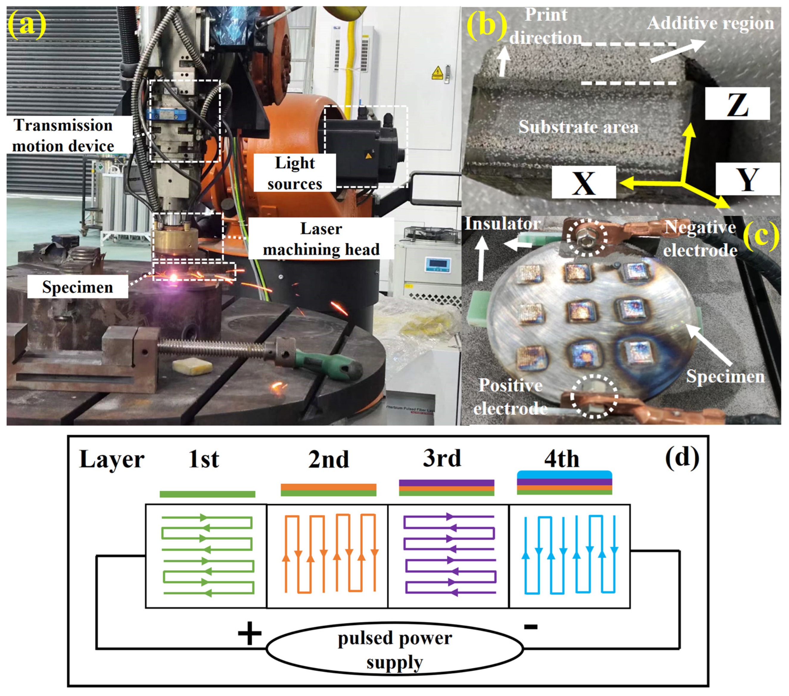
2.2. LP-DED Method
2.3. Characterization Methods
3. Results
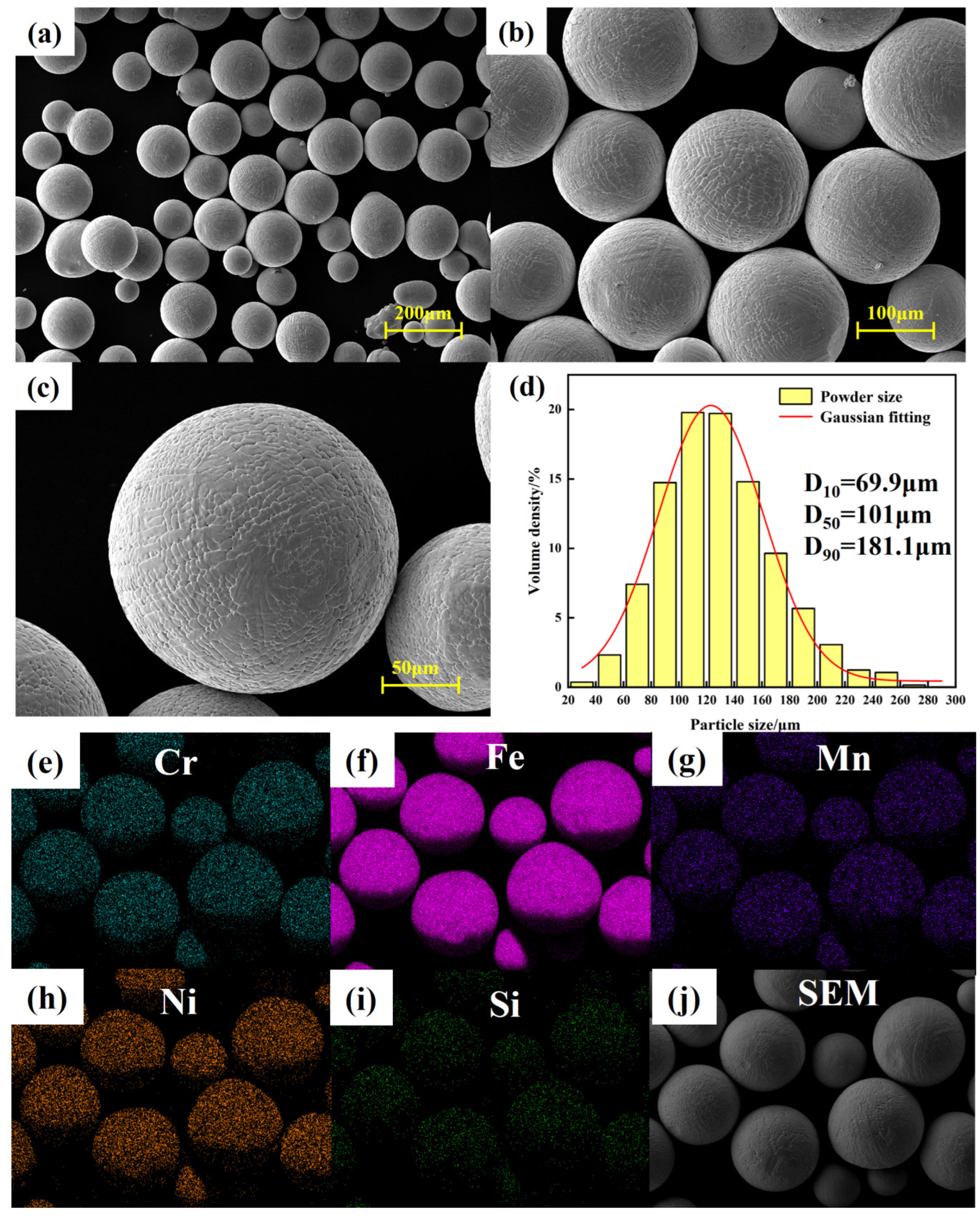
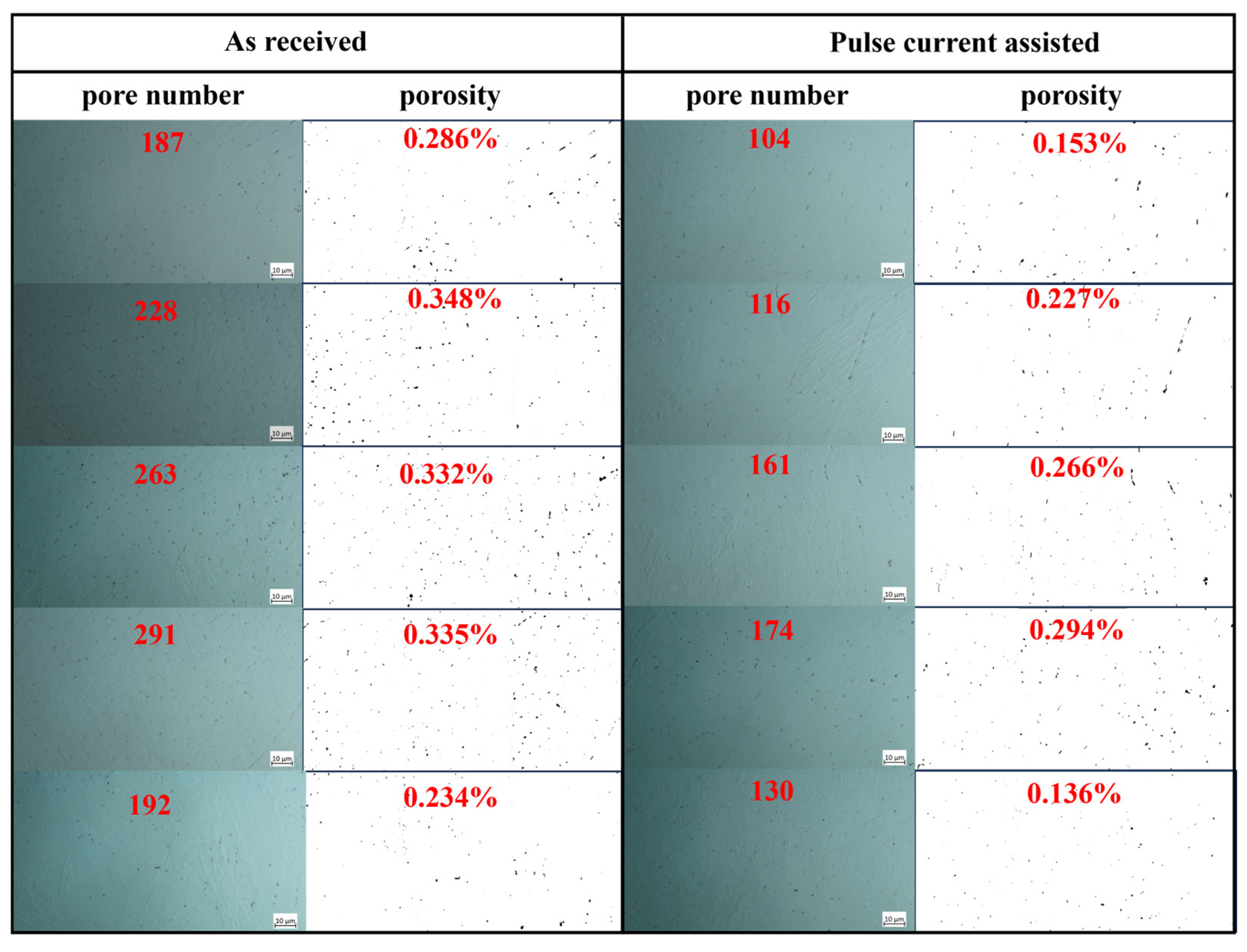
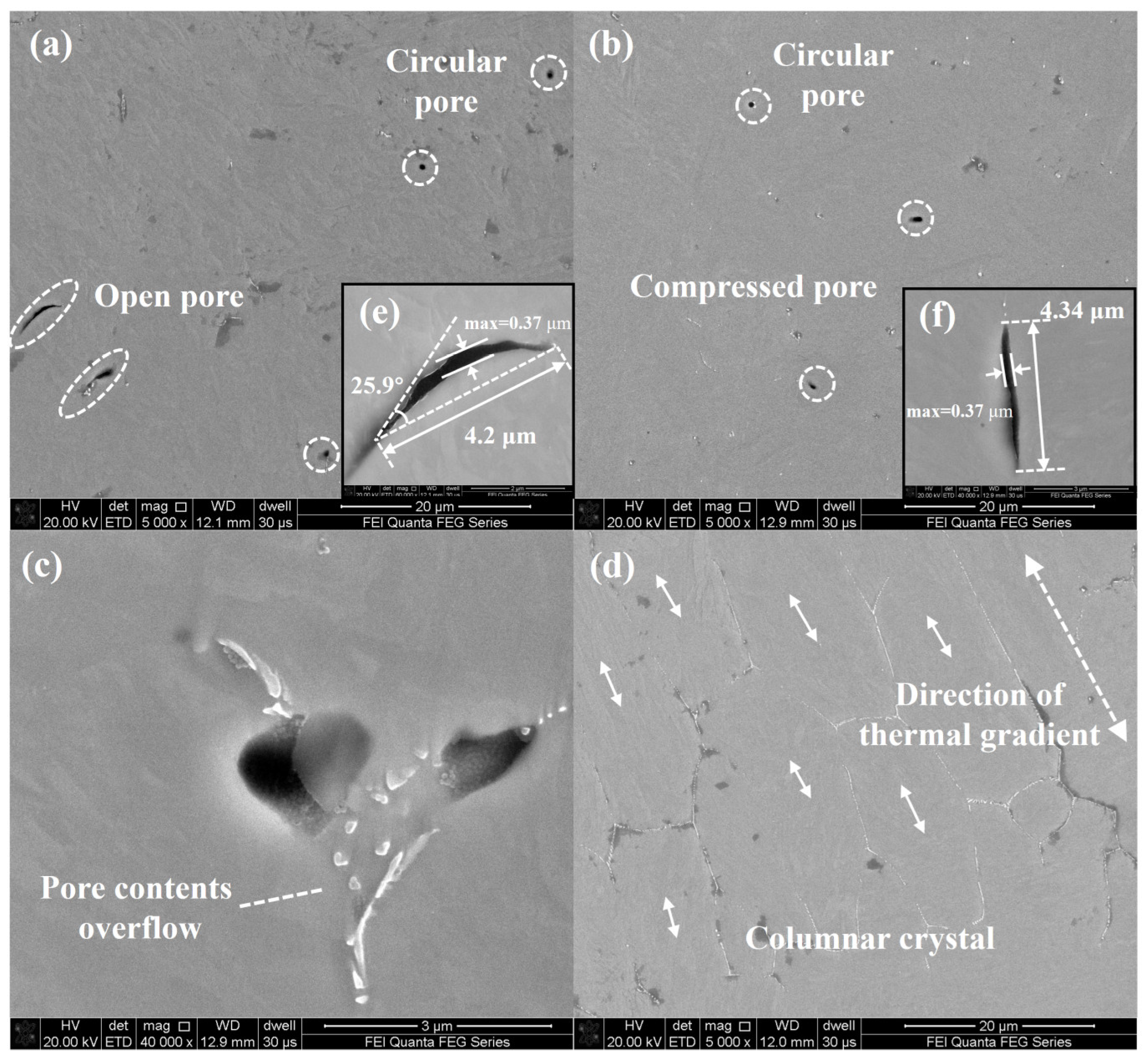
3.1. Morphology and Pore Characterization
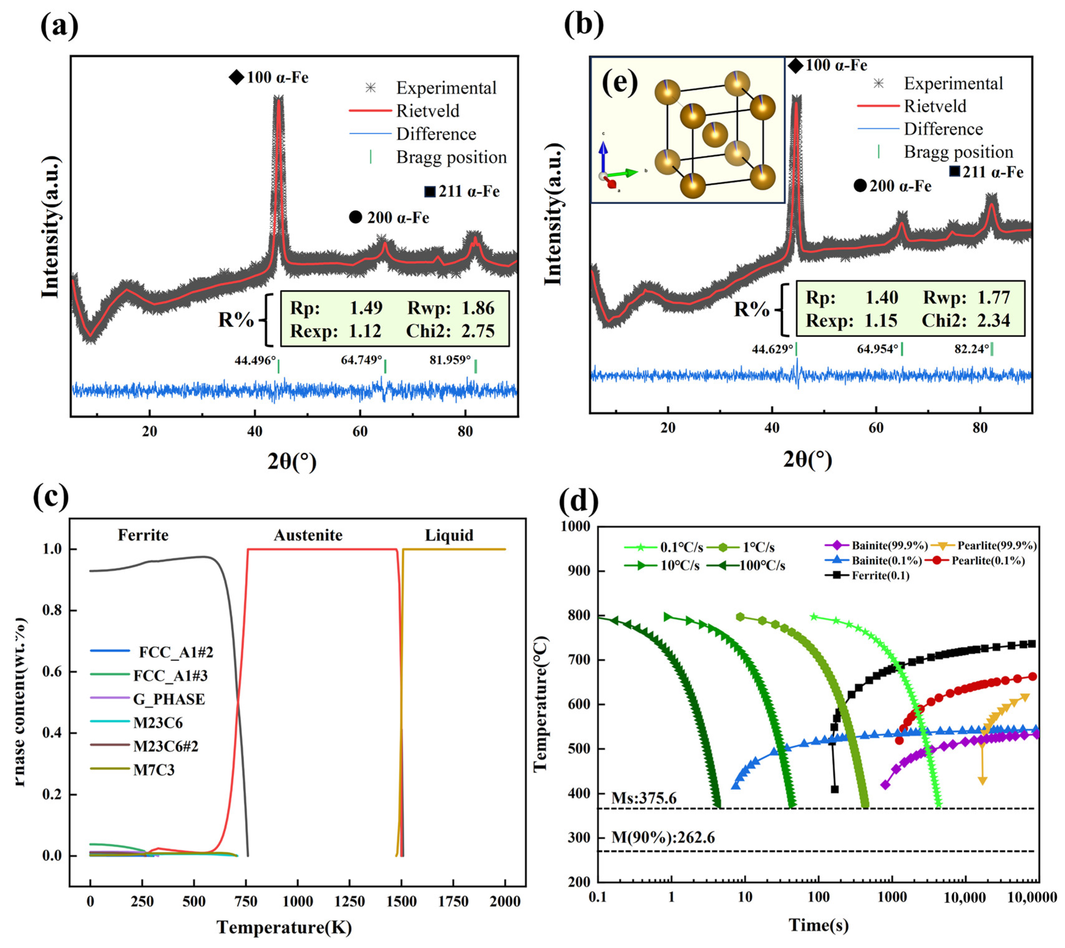
3.2. Phase Analysis by XRD
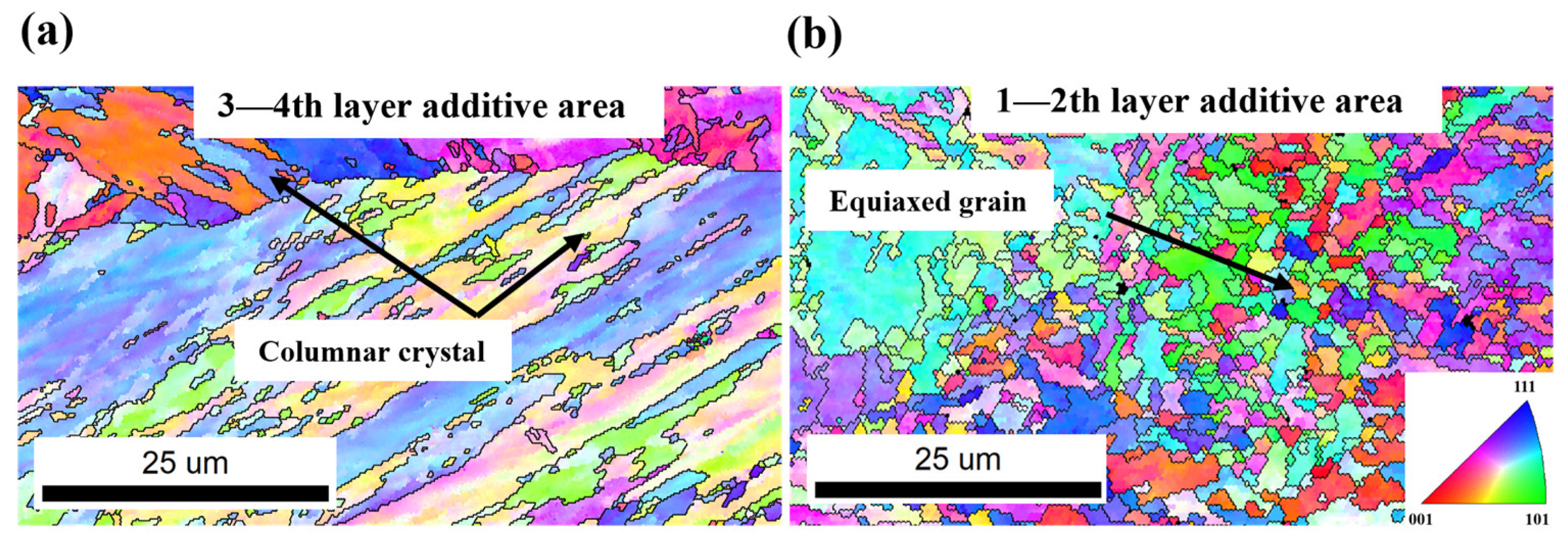
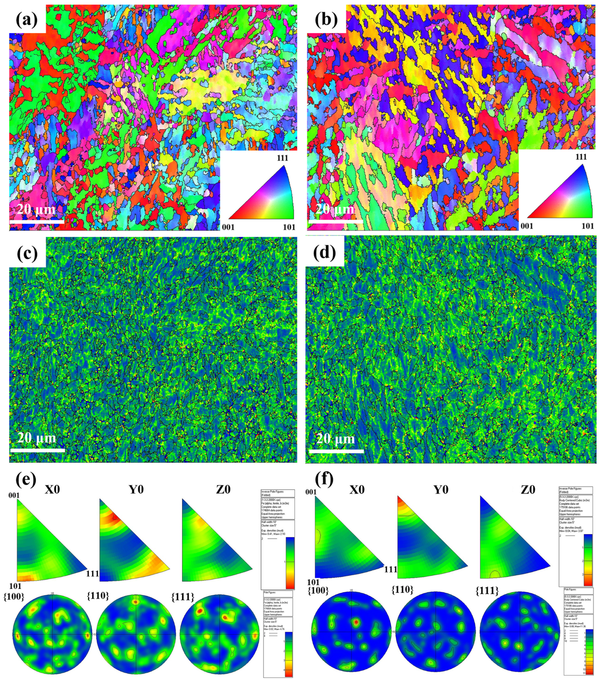
3.3. Microstructure Analysis by EBSD
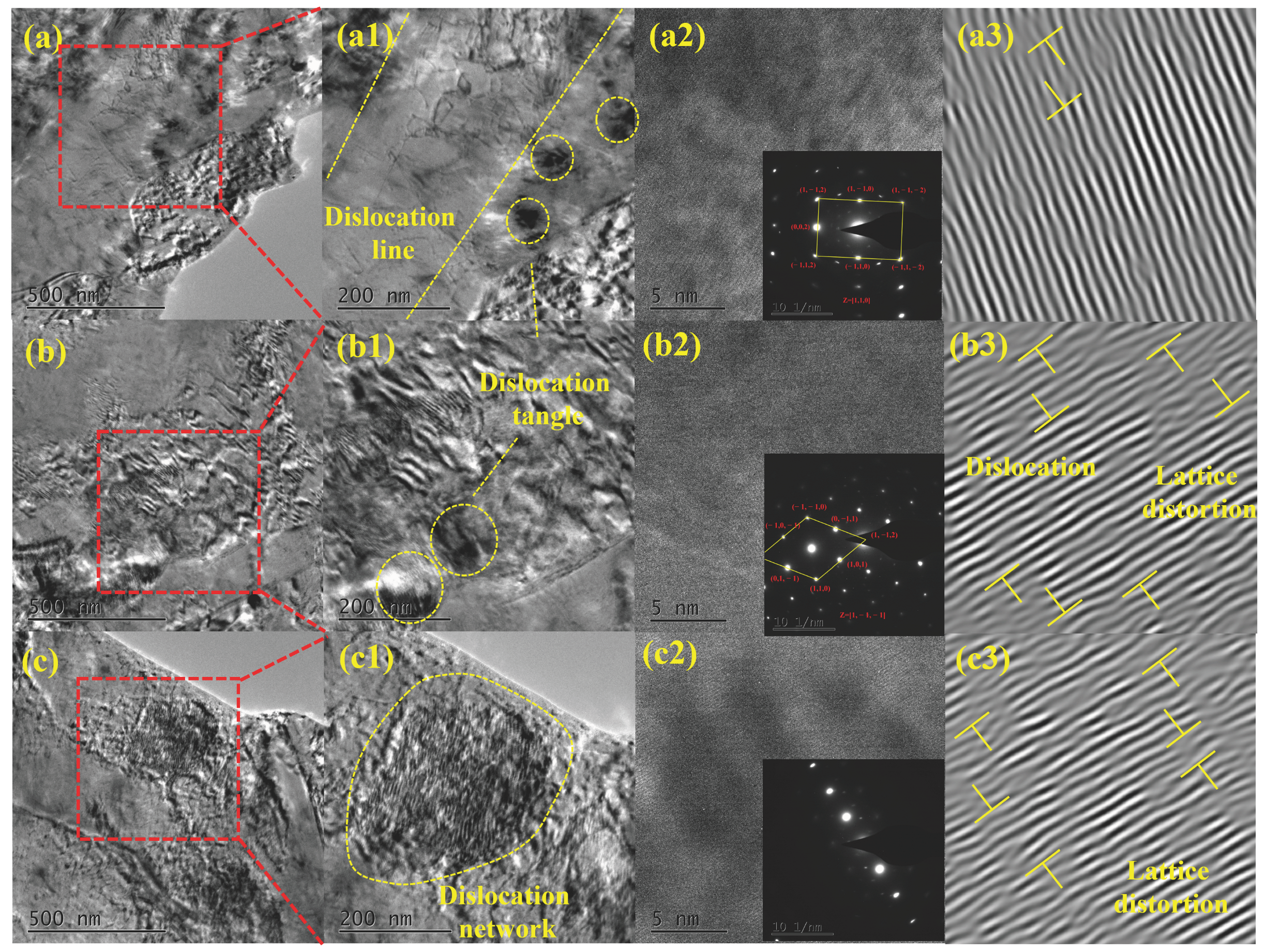
3.4. Dislocation Defects by TEM
4. Discussion
4.1. Thermal Effects of Pulsed Current
4.2. Mechanical and Microstructural Effects of Pulsed Current
4.3. Potential Implications for Hydrogen Embrittlement and Wear Resistance
5. Conclusions
Author Contributions
Funding
Data Availability Statement
Conflicts of Interest
Abbreviations
| BCC | body-centered cubic |
| EBSD | electron back scatter diffraction |
| EDS | energy dispersive spectrometer |
| FWHM | full width at half maximum |
| LP-DED | laser powder directed energy deposition |
| XRD | X-ray diffractometer |
References
- Jendrzej, S.; Gondecki, L.; Debus, J.; Moldenhauer, H.; Tenberge, P.; Barcikowski, S.; Gökce, B. Tribological properties of laser-generated hard ceramic particles in a gear drive contact. Appl. Surf. Sci. 2019, 467–468, 811–818. [Google Scholar] [CrossRef]
- Yan, H.; Wei, P.; Su, L.; Liu, H.; Wei, D.; Zhang, X.; Deng, G. Rolling-sliding contact fatigue failure and associated evolutions of microstructure, crystallographic orientation and residual stress of AISI 9310 gear steel. Int. J. Fatigue 2023, 170, 107511. [Google Scholar] [CrossRef]
- Lee, T.; Jeong, W.; Chung, S.; So, K.P.; Ryu, H.J. Novel solid-state metal powder surface modification process for additive manufacturing of metal matrix composites and alloys. Appl. Surf. Sci. 2023, 615, 156364. [Google Scholar] [CrossRef]
- Syed, W.U.H.; Pinkerton, A.J.; Li, L. Combining wire and coaxial powder feeding in laser direct metal deposition for rapid prototyping. Appl. Surf. Sci. 2006, 252, 4803–4808. [Google Scholar] [CrossRef]
- He, X.; Song, L.; Yu, G.; Mazumder, J. Solute transport and composition profile during direct metal deposition with coaxial powder injection. Appl. Surf. Sci. 2011, 258, 898–907. [Google Scholar] [CrossRef]
- Ngo, T.D.; Kashani, A.; Imbalzano, G.; Nguyen, K.T.Q.; Hui, D. Additive manufacturing (3D printing): A review of materials. methods, applications and challenges. Compos. Part B Eng. 2018, 143, 172–196. [Google Scholar] [CrossRef]
- Song, Y.; Wu, W.; Yu, Y.; Hua, L. Effects of Electric and Magnetic Treatments on Microstructures of Solid Metals: A Review. Chin J. Mech. Eng. 2023, 36, 121–139. [Google Scholar] [CrossRef]
- Zhao, Y.; Wu, M.; Hou, J.; Chen, Y.; Zhang, C.; Cheng, J.; Li, R. Microstructure and high temperature properties of laser cladded WTaNbMo refractory high entropy alloy coating assisted with ultrasound vibration. J. Alloys Compd. 2022, 920, 165888. [Google Scholar] [CrossRef]
- Zhai, L.L.; Ban, C.Y.; Zhang, J.W. Investigation on laser cladding Ni-base coating assisted by electromagnetic field. Opt. Laser Technol. 2019, 114, 81–88. [Google Scholar] [CrossRef]
- Li, X.; Peng, J.; Wang, F.; Liu, Z.; Feng, X. Effect of Electrically Assisted Preheating on Microstructure and Properties of Laser-Cladded Co-Based Coating on CP-Ti Alloy Substrate. Coatings 2023, 13, 1379. [Google Scholar] [CrossRef]
- Zhai, L.; Wang, Q.; Zhang, J.; Ban, C. Effect of alternating current electric field on microstructure and properties of laser cladding Ni–Cr–B–Si coating. Ceram. Int. 2019, 45, 16873–16879. [Google Scholar] [CrossRef]
- Xu, L.; Wang, D. Ni-Based Alloy Coating Prepared by Laser Cladding Strengthened by Follow-up Feed Pulse Current. Chin. J. Lasers 2020, 47, 97–104. [Google Scholar]
- Wang, F.; Liu, Y.; Tong, Y.; Zhang, C.; Jiang, F.; Wang, J. Effect of electropulsing on anisotropy in strength of laser metal deposited Ti−6Al−4V alloy. Trans. Nonferr. Metals Soc. 2022, 32, 2578–2586. [Google Scholar] [CrossRef]
- Lu, Y.; Sun, G.; Wang, Z.; Zhang, Y.; Su, B.; Feng, A.; Ni, Z. Effects of electromagnetic field on the laser direct metal deposition of austenitic stainless steel. Opt. Laser Technol. 2019, 119, 105586. [Google Scholar] [CrossRef]
- Bi, J.; Wu, L.; Liu, Z.; Wang, H.; Li, S.; Wang, J.; Yang, Z.; Lu, N.; Chen, X.; Starostenkov, M.D.; et al. Microstructure, mechanical properties and multiphase synergistic strengthening mechanisms of a novel laser additive manufactured AlNi6TiZr alloy. J. Mater. Sci. Technol. 2024, 178, 59–69. [Google Scholar] [CrossRef]
- Zhang, K.; Wang, S.; Liu, W.; Long, R. Effects of substrate preheating on the thin-wall part built by laser metal deposition shaping. Appl. Surf. Sci. 2014, 317, 839–855. [Google Scholar] [CrossRef]
- Nie, J.; Chen, C.; Liu, L.; Wang, X.; Zhao, R.; Shuai, S.; Wang, J.; Ren, Z. Effect of substrate cooling on the epitaxial growth of Ni-based single-crystal superalloy fabricated by direct energy deposition. J. Mater. Sci. Technol. 2021, 62, 148–161. [Google Scholar] [CrossRef]
- Yu, J.; Zhang, H.; Deng, D.; Hao, S.; Iqbal, A. Numerical calculation and experimental research on crack arrest by detour effect and joule heating of high pulsed current in remanufacturing. Chin. J. Mech. Eng. 2014, 27, 745–753. [Google Scholar] [CrossRef]
- Jochen, T.; Felix, S. Uniform fatigue damage tolerance assessment for additively manufactured and cast Al-Si alloys: An elastic-plastic fracture mechanical approach. Addit. Manuf. Lett. 2022, 58, 100054. [Google Scholar]
- Zhou, S.; Huang, Y.; Zeng, X.; Hu, Q. Microstructure characteristics of Ni-based WC composite coatings by laser induction hybrid rapid cladding. Mater. Sci. Eng. A 2008, 480, 564–572. [Google Scholar] [CrossRef]
- Xie, D.; Zhao, J.; Qi, Y.; Li, Y.; Shen, L.; Xiao, M. Decreasing pores in a laser cladding layer with pulsed current. Chin. Opt. Lett. 2013, 11, 111401. [Google Scholar] [CrossRef]
- Liverani, E.; Toschi, S.; Ceschini, L.; Fortunato, A. Effect of selective laser melting (SLM) process parameters on microstructure and mechanical properties of 316L austenitic stainless steel. J. Mater. Process. Technol. 2017, 249, 255–263. [Google Scholar] [CrossRef]
- Suryawanshi, J.; Prashanth, K.G.; Ramamurty, U. Tensile, fracture, and fatigue crack growth properties of a 3D printed maraging steel through selective laser melting. J. Alloys Compd. 2017, 725, 355–364. [Google Scholar] [CrossRef]
- Hajiabadi, M.G.; Zamanian, M.; Souri, D. Williamson-Hall analysis in evaluation of lattice strain and the density of lattice dislocation for nanometer scaled ZnSe and ZnSe:Cu particles. Ceram. Int. 2019, 45, 14084–14089. [Google Scholar] [CrossRef]
- Yang, F.; Zhao, T.; He, P.; Zhou, L.; Pan, X.; Liang, X.; Jia, W.; An, Z.; Liu, P.; Zhang, H. Effect of pulsed femtosecond laser shock peening surface modification on anti-wear failure properties of AISI 9310 gear steel. Eng. Fail. Anal. 2024, 159, 108146. [Google Scholar] [CrossRef]
- Pope, C.G. X-Ray Diffraction and the Bragg Equation. J. Chem. Educ. 1997, 74, 129. [Google Scholar] [CrossRef]
- Fan, W.; Wang, J.; Peng, Y.; Tan, H.; Wang, Y.; Qi, Y.; Feng, Z.; Zhang, F.; He, B.; Lin, X. Microstructure and mechanical properties of an ultra-high strength steel fabricated by laser hybrid additive manufacturing. Mater. Sci. Eng. A 2023, 885, 145594. [Google Scholar] [CrossRef]
- Tao, Y.; Xiaohu, Z.; Xiaoqing, J.; Xuelei, R.; Boyang, L. Mechanism of Grain Refinement of Pulse Current Assisted Plasma Arc Welded Al-Mg Alloy. Acta Metall. Sin. 2024, 60, 323–332. [Google Scholar]
- Wu, C.; Zhao, Y.; Xu, X.; Zhou, Y.; Yan, X.; Wu, Z.; We, L.; Qiu, X. Electropulse-induced texture elimination and <100> texture formation in hot-rolled annealed 35CrMo steel. J. Mater. Res. Technol. 2023, 24, 1537–1546. [Google Scholar]
- Fujii, H.; Sato, T.; Lu, S.; Nogi, K. Development of an advanced A-TIG (AA-TIG) welding method by control of Marangoni convection. Mater. Sci. Eng. A 2008, 495, 296–303. [Google Scholar] [CrossRef]
- Wang, C.; Luo, K.; Wang, J.; Lu, J. Carbide-facilitated nanocrystallization of martensitic laths and carbide deformation in AISI 420 stainless steel during laser shock peening. Int. J. Plast. 2022, 150, 103191. [Google Scholar] [CrossRef]
- Song, J.; He, W.; Liang, X.; Cao, Z.; Pang, Z.; Zhao, W.; Luo, S. Enhanced carbon diffusion efficiency and work hardening effect of AISI 9310 steel via pre-laser shock peening. Surf. Coat. Technol. 2023, 473, 129932. [Google Scholar] [CrossRef]
- Liu, J.; Zhang, X.; Pelenovich, V.; Xu, Y.; Tan, K.; Hu, L.; Zeng, X.; Zeng, Z.; Lei, Y.; Chen, Y.; et al. Effects of duty cycle on microstructure and mechanical properties of (AlCrNbSiTi)N high-entropy nitride hard coatings deposited by pulsed arc ion plating. Vacuum 2024, 225, 113219. [Google Scholar] [CrossRef]
- Ye, Y.; Wang, H.; Tang, G.; Song, G. Effect of Electropulsing-Assisted Ultrasonic Nanocrystalline Surface Modification on the Surface Mechanical Properties and Microstructure of Ti-6Al-4V Alloy. J. Mater. Eng. Perform. 2018, 27, 2394–2403. [Google Scholar] [CrossRef]
- Dimitrov, N.K.; Liu, Y.; Horstemeyer, M.F. Electroplasticity: A review of mechanisms in electro-mechanical coupling of ductile metals. Mech. Adv. Mater. Struc. 2022, 29, 705–716. [Google Scholar] [CrossRef]
- Rudolf, C.; Goswami, R.; Kang, W.; Thomas, J. Effects of electric current on the plastic deformation behavior of pure copper, iron, and titanium. Acta Mater. 2021, 209, 116776. [Google Scholar] [CrossRef]
- Ben, D.D.; Yang, H.J.; Ma, Y.R.; Shao, X.H.; Pang, J.C.; Zhang, Z.F. Rapid hardening of AISI 4340 steel induced by electropulsing treatment. Mater. Sci. Eng. A 2018, 725, 28–32. [Google Scholar] [CrossRef]
- Zhou, Y.; Zhang, W.; Wang, B.; He, G.; Guo, J. Grain refinement and formation of ultrafine-grained microstructure in a low-carbon steel under electropulsing. J. Mater. Res. 2002, 17, 2105–2111. [Google Scholar] [CrossRef]
- Guan, T.; Chen, S.; Chen, X.; Liang, J.; Liu, C.; Wang, M. Effect of laser incident energy on microstructures and mechanical properties of 12CrNi2Y alloy steel by direct laser deposition. J. Mater. Sci. Technol. 2019, 35, 395–402. [Google Scholar] [CrossRef]
- Zhao, S.; Zhang, R.; Chong, Y.; Li, X.; Abu-Odeh, A.; Rothchild, E.; Chrzan, D.C.; Asta, M.; Morris, J.W.; Minor, A.M. Defect reconfiguration in a Ti–Al alloy via electroplasticity. Nat. Mater. 2021, 20, 468–472. [Google Scholar] [CrossRef]
- Sobola, D.; Dallaev, R. Exploring Hydrogen Embrittlement: Mechanisms, Consequences, and Advances in Metal Science. Energies 2024, 17, 2972. [Google Scholar] [CrossRef]
- Chen, Y.S.; Huang, C.; Liu, P.Y.; Yen, H.W.; Niu, R.; Burr, P.; Moore, K.L.; Martínez-Pañeda, E.; Atrens, A.; Cairney, J.M. Hydrogen trapping and embrittlement in metals—A review. Int. J. Hydrogen Energy 2024. Advance online publication. [Google Scholar] [CrossRef]
- Li, S.S.; Chen, Y.; Zhang, Y.Y.; Qiu, F.; Zeng, F.; Shi, L. Prenatal exercise reprograms the development of hypertension progress and improves vascular health in SHR offspring. Vasc. Pharmacol. 2021, 139, 106885. [Google Scholar] [CrossRef] [PubMed]
- Bateni, M.R.; Szpunar, J.A.; Wang, X. Wear and corrosion wear of medium carbon steel and 304 stainless steel. Wear 2004, 260, 116–122. [Google Scholar] [CrossRef]
- Zhang, K.D.; Deng, J.X.; Meng, R.; Lei, S.; Yu, X. Influence of laser substrate pretreatment on anti-adhesive wear properties of WC/Co-based TiAlN coatings against AISI 316 stainless steel. Int. J. Refract. Met. Hard Mater. 2016, 57, 101–114. [Google Scholar] [CrossRef]
- Zheng, Q.; Yao, W.X.; Lim, L.-C. Ostwald ripening and grain growth in Ti(C,N)-based cermets during liquid phase sintering. Int. J. Refract. Met. Hard Mater. 2016, 58, 1–7. [Google Scholar] [CrossRef]


| C | Mn | Si | S | Cr | Ni | Mo | Cu | Fe |
|---|---|---|---|---|---|---|---|---|
| 0.11 | 0.56 | 0.24 | 0.004 | 1.32 | 3.19 | 0.12 | 0.13 | Bal |
| Sample Type | hkl | FWHM | Peak Intensity | Crystal Lattice Spacing | Lattice Constant | Mean Lattice Constant |
|---|---|---|---|---|---|---|
| As received | 100 | 0.386 | 100 | 2.0514 | 2.0514 | 6.2155 |
| 200 | 0.072 | 9.5 | 1.4368 | 8.2576 | ||
| 211 | 0.102 | 15 | 1.1788 | 8.3374 | ||
| Pulsed current assisted | 100 | 0.102 | 100 | 2.0283 | 2.0283 | 6.1599 |
| 200 | 0.101 | 17.7 | 1.4372 | 8.2621 | ||
| 211 | 0.227 | 22.7 | 1.1683 | 8.1895 |
Disclaimer/Publisher’s Note: The statements, opinions and data contained in all publications are solely those of the individual author(s) and contributor(s) and not of MDPI and/or the editor(s). MDPI and/or the editor(s) disclaim responsibility for any injury to people or property resulting from any ideas, methods, instructions or products referred to in the content. |
© 2025 by the authors. Licensee MDPI, Basel, Switzerland. This article is an open access article distributed under the terms and conditions of the Creative Commons Attribution (CC BY) license (https://creativecommons.org/licenses/by/4.0/).
Share and Cite
Xie, C.; Yang, F.; He, P.; Liu, W.; Feng, Q.; Zhou, L.; Liu, P.; Sun, X. Effect of In-Situ Pulse Current on Microstructure and Mechanical Properties of AISI 9310 Gear Steel by Laser Powder Directed Energy Deposition. Machines 2025, 13, 308. https://doi.org/10.3390/machines13040308
Xie C, Yang F, He P, Liu W, Feng Q, Zhou L, Liu P, Sun X. Effect of In-Situ Pulse Current on Microstructure and Mechanical Properties of AISI 9310 Gear Steel by Laser Powder Directed Energy Deposition. Machines. 2025; 13(4):308. https://doi.org/10.3390/machines13040308
Chicago/Turabian StyleXie, Cenchao, Fei Yang, Peng He, Wenfa Liu, Qiang Feng, Liucheng Zhou, Ping Liu, and Xin Sun. 2025. "Effect of In-Situ Pulse Current on Microstructure and Mechanical Properties of AISI 9310 Gear Steel by Laser Powder Directed Energy Deposition" Machines 13, no. 4: 308. https://doi.org/10.3390/machines13040308
APA StyleXie, C., Yang, F., He, P., Liu, W., Feng, Q., Zhou, L., Liu, P., & Sun, X. (2025). Effect of In-Situ Pulse Current on Microstructure and Mechanical Properties of AISI 9310 Gear Steel by Laser Powder Directed Energy Deposition. Machines, 13(4), 308. https://doi.org/10.3390/machines13040308