Abstract
To improve the thermal performance of air-cooled panel-type radiators for transformers, a multi-fan horizontal blowing method was designed in this paper, and the thermo-hydraulic performance of the oil-side and air-side of the panel-type radiator was investigated with a simplified numerical method and experiments. The uniform air distribution and zoned heat dissipation ideas were used for three blowing methods, which can increase the proportion of air supply for the high-temperature area of the radiator and apply multiple fans for zoned heat dissipation of the insulating oil in the radiator. Then, the effect of different insulating oil flow rates on the heat dissipation performance of the panel-type radiator was investigated. It was shown that the computational time for the simplified numerical simulation method used for an air-cooled panel-type radiator could be effectively shortened with a small relative error. Due to a more uniform air supply and prioritized air distribution for the high-temperature areas using the multi-fan horizontal blowing method, the overall heat dissipation efficiency was improved. Among the three blowing methods, the best heat dissipation performance was obtained by using the six-fan horizontal blowing scheme, which can improve the performance by about 10.42% and 15.44% in experimental and numerical studies, respectively, as compared with the traditional blowing method.
1. Introduction
Oil-immersed transformers are among the most commonly used power transformers, with the hot spot temperature of their windings being a key factor in determining their load capacity. Hot spot temperature should be controlled within specified limits to prevent deterioration of insulation properties and extend the lifespan of the transformer [1,2]. Panel-type radiators are preferred for augmenting the thermal performance of oil-immersed transformers owing to their ease of fabrication, simplicity of operation, safety and reliability [3]. According to different auxiliary devices, the cooling mode of the panel-type radiators can be mainly divided into oil-natural air-natural (ONAN), oil-natural air-forced (ONAF), oil-forced air-natural (OFAN), oil-forced air-forced (OFAF), and oil-directed air-natural (ODAF) [4,5]. Research on the cooling performance of panel-type radiators under different cooling modes has received extensive attention from scholars [6,7]. However, there has been relatively little research on radiators in AF mode, particularly regarding the effects of their external auxiliary devices, mainly fans, on the thermal performance of these panel-type radiators.
Previous research on panel-type radiators in AF mode has been carried out mainly on the vertical blow and horizontal blow used for panel-type radiators in industrial practice. The heat transfer performance of five parallel connected panel-type radiators in ONAF mode was investigated by Paramane et al. [8] under vertical blowing and horizontal blowing conditions through numerical simulation and experiments. It was found that the heat dissipation of the third radiator was 15% less than that of the two end radiators in vertical blowing mode, while their heat dissipation performance in horizontal blowing mode decreased gradually with the increase in the distance from the fan. Moreover, the total heat dissipation of the vertical blow was 6.1% higher than that of the horizontal blow due to air leakages from both sides. Subsequently, Paramane [9] conducted visualization experiments using thin strands of cotton and combined them with numerical simulations to identify areas of air leakage near the radiator. Numerical simulations were carried out by Kim and Ha [10] to evaluate the thermal performance of a cooling system consisting of three fans and five panel-type radiators (OFAF) in horizontal blow and vertical blow mode, where the oil side flow was modeled by the porous media approach. The results showed that the cooling performance of a single radiator in different blowing methods was mainly due to the distance between the cooling fan and the radiator. In addition, in a cooling system consisting of five panel-type radiators, the cooling performance of the radiators in horizontal blowing mode was always greater than that in vertical blowing mode, regardless of the flow rate of the insulating oil. The thermal performance of an ON mode panel-type radiator with vertical and horizontal blow was numerically analyzed by Taghikhani and Afshar [11]. It was shown that horizontal blow improved thermal performance by 8.9%, as compared to vertical blow. In addition, they also conducted accident risk assessments for both arrangements and obtained better risk resistance in the horizontal blow mode. The above studies have shown that the panel-type radiator arrays with horizontal blowing fans have a higher thermal efficiency than vertical blowing under the same conditions due to less fan air leakage and more radiators being covered by the fan. Garelli et al. [12] investigated the thermal performance of an ONAF mode panel-type radiator under bottom blowing conditions by numerical simulation and experiment. A semi-analytical reduced model was proposed to guide the design of the panel-type radiator. Wang et al. [13,14] numerically analyzed the flow and heat transfer characteristics of the ONAF mode panel-type radiator under vertical blowing conditions. The region with high temperature was identified, and an early fault detection method based on the oil exponent for transformer fans was proposed.
In addition to the traditional blowing mode, some new fan arrangements were also designed to achieve better-enhanced heat transfer effects. The effects of the blowing direction and the horizontal blowing fan offset on the cooling performance of the panel-type radiator in ONAF mode were investigated by Paramane et al. [15] by numerical simulation and experiment. The results showed that blowing vertically from the bottom of the radiator causes airflow to escape from the sides, decreasing the heat transfer performance of the radiator. In addition, the offset of the top and bottom fans (50 mm) could improve the cooling performance of radiators by 3%. Subsequently, Paramane et al. [16] compared the heat dissipation performance of panel-type radiators in four novel blowing methods. The four types of blowing methods ranked by cooling performance from highest to lowest are one-sided mounted fans, bottom-mounted fans, opposite-side mounted fans at the top, and opposite-side mounted fans with one at the top and one at the bottom. The thermal performance of five panel-type radiators (OF) in nine combinations of vertical blowing and horizontal blowing fan arrangements was separately compared by Kim et al. [17] through experimental and numerical simulation. The results of the study showed that fans caused mutual reinforcement between the vertical and horizontal airflows. When the bottom fan was located at the center of the radiator array and the side fan was located in the lower half of the radiator array, the best cooling performance was obtained regardless of the insulating oil flow rate. The cooling performance of the novel blowing method was at least about 22% higher than the worst one at any oil flow rate. Yun et al. [18] conducted a numerical comparison of the heat dissipation performance of four panel-type radiators, using nine different fan arrangements that combined vertical and horizontal airflow. The results showed that the best heat dissipation performance of the radiator array was achieved when a vertical fan was close to the side of the radiator array and a horizontal fan was centered. Additionally, the total cooling efficiency was reduced by increasing the total fan pressure, which aligned with the experience that low-pressure fans were often used for panel-type radiators equipped with fans. Fdhila et al. [19] simplified the numerical model of panel-type radiators using the porous media approach and investigated the effect of fan size and number of vertical fans on the heat dissipation performance of panel-type radiators in ONAF mode. About a 5–10% higher cooling performance was obtained when installing multiple small-size fans since multi-fan blows air more evenly, provided the total flow rate was the same. A first step toward uniform airflow by multiple fans for panel-type radiators was introduced by Fdhila. However, the effect of the blowing area has not been excluded from their work, so it was impossible to rigorously prove the superiority of multi-fan blow. Apart from that, their work only focused on the vertical blowing condition, and the study of the flow and heat characteristics of the panel-type radiator under horizontal blowing conditions by multiple fans with different arrangements has not been reported in the relevant open literature. Therefore, there was a need for additional research focused on multi-fan vertical blow.
So far, plenty of CFD simulations and experiments on panel-type radiators have been carried out by scholars, and CFD simulations based on the finite volume method (FVM) or the finite element method (FEM) have been proven to be a reliable tool for describing the flow and heat transfer process of the radiator under different working modes.
Among their studies, a large number of simplifications were implemented to the flow heat transfer characteristics of the panel-type radiator in AF mode. The literature [9,11,12,15,16,18] took a linear wall temperature simplification instead of direct simulations of the oil side for the panel-type radiator, and this simplification completely ignored the effects of the flow and heat transfer of internal insulating oil generated by the external fans. The literature [10,17] used the porous medium approach to model the oil side, which also could not accurately obtain the flow and heat transfer characteristics on the oil side, although the coupling of the internal and external temperature fields was considered. Although less simplified on the oil side, the literature [13,14] configured an internal constant flow rate instead of simulating complete fans. Their methods ignored the rotational velocity component of the fans, leading to the distortion of the airflow field [20]. However, a complete modeling and simulation of the oil and air side of the radiator and the fan area were performed by the literature [8]. Because of the large geometric volume and the complexity of the flow and heat transfer process, it took about 500 h to compute one simulation in a workstation with a clock speed of 3.33 GHz and 64 GB RAM. Therefore, it is valuable to reasonably simplify the numerical model of the panel-type radiator in AF mode to reduce the cost of computation and shorten the calculation time while retaining the flow heat transfer characteristics of the panel-type radiator in AF mode as much as possible and ensuring the calculation accuracy.
Based on the above discussion, numerical simulations and experiments for improving heat dissipation of a panel-type radiator through multi-fan horizontal blowing are conducted in this work. The flow and heat transfer characteristics under four types of fan arrangement for a panel-type radiator are analyzed to provide guidance for enhancing heat dissipation performance with multi-fan arrangements for panel-type radiator arrays. The main research contents are as follows: (1) Three new multi-fan horizontal blowing schemes are designed to rationally simplify the numerical model of the panel-type radiator in AF mode, and the accuracy of the simplified model is verified by experiments; (2) The flow and heat transfer characteristics of the oil side and air side are analyzed through numerical simulation, and the heat transfer enhancement performance of the panel-type radiator under different fan arrangements is compared through experiments.
2. Physical Description of the Study
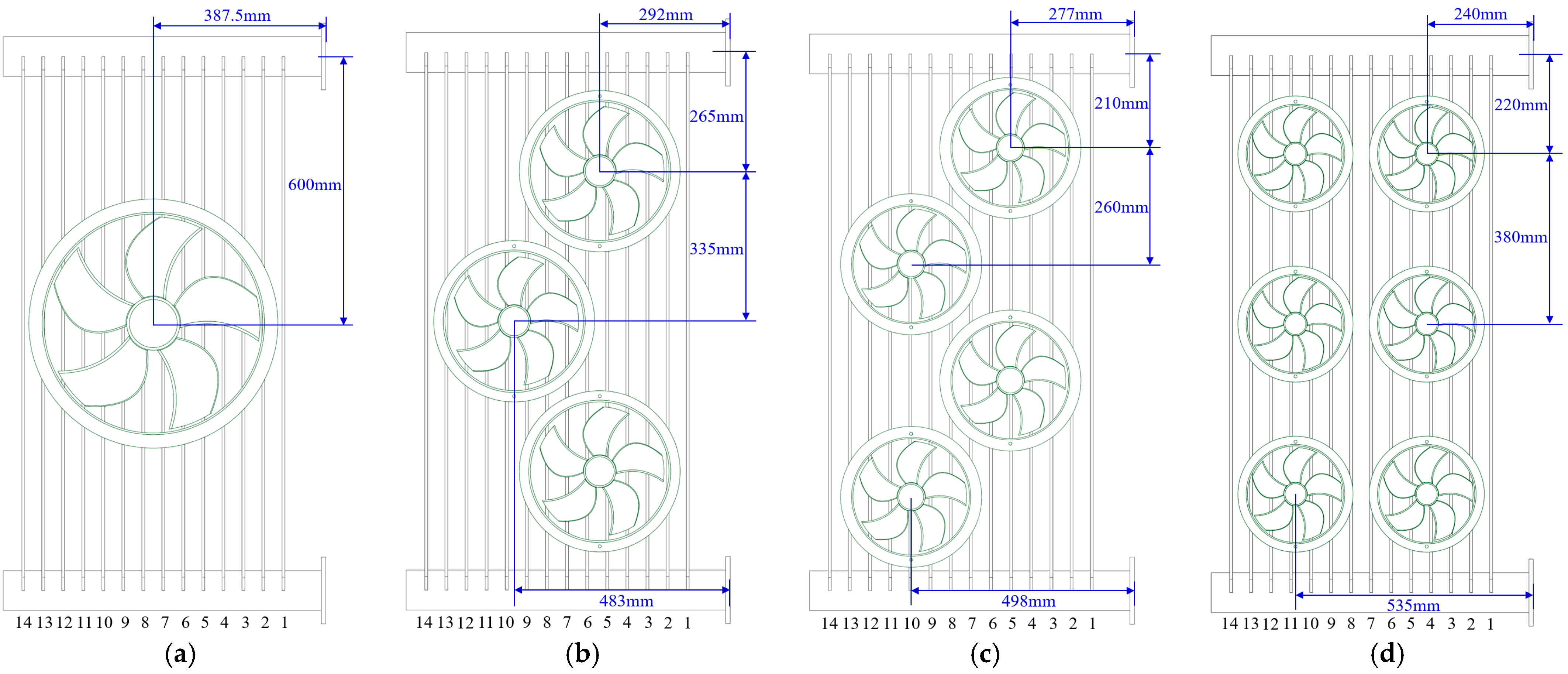
In this study, four types of fan arrangements are designed for Cases 0–3, as shown in Figure 1a–d. The panel-type radiator’s flow and heat transfer characteristics of the oil side and air side under different fan arrangements are investigated through experiments and numerical simulations. As shown in Figure 1a, Case 0 is a conventional arrangement with a single horizontal fan whose axis of rotation is located between the seventh and eighth radiator fins. Figure 1b shows a scheme of three-fan horizontal blowing (Case 1). Compared with Case 0, the size of the fans is reduced in Case 1, where two of the fans are close to the inlet and outlet of the insulating oil, and the third fan is located away from the oil inlet and outlet. As shown in Figure 1c, a four-fan horizontal blowing arrangement is adopted by Case 2. In this case, the fan’s size is further reduced, and these fans are staggered left and right along the height of the panel-type radiator. As shown in Figure 1d, Case 3 utilizes a horizontal blowing arrangement of 6 small fans, where the fans are evenly distributed on the lateral of the panel-type radiator.
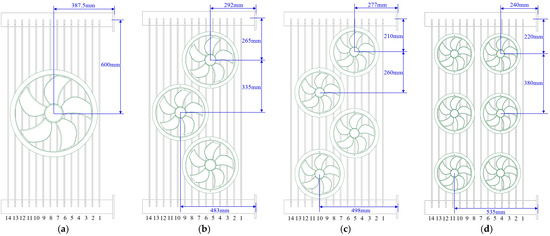
Figure 1.
Schematic diagram of different fan arrangements: (a) Case 0; (b) Case 1; (c) Case 2; (d) Case 3.
Different parameters used in Cases 0–3 are listed in Table 1. According to the literature [18], this work controls the fan total pressure to be equal for each case and ensures that each case has a similar total blowing area.

Table 1.
Parameters of fans used in different cases.
Sfan can be expressed as Equation (1):
where n is the fan number.
3. Numerical Approach
3.1. Physical Model and Boundary Conditions
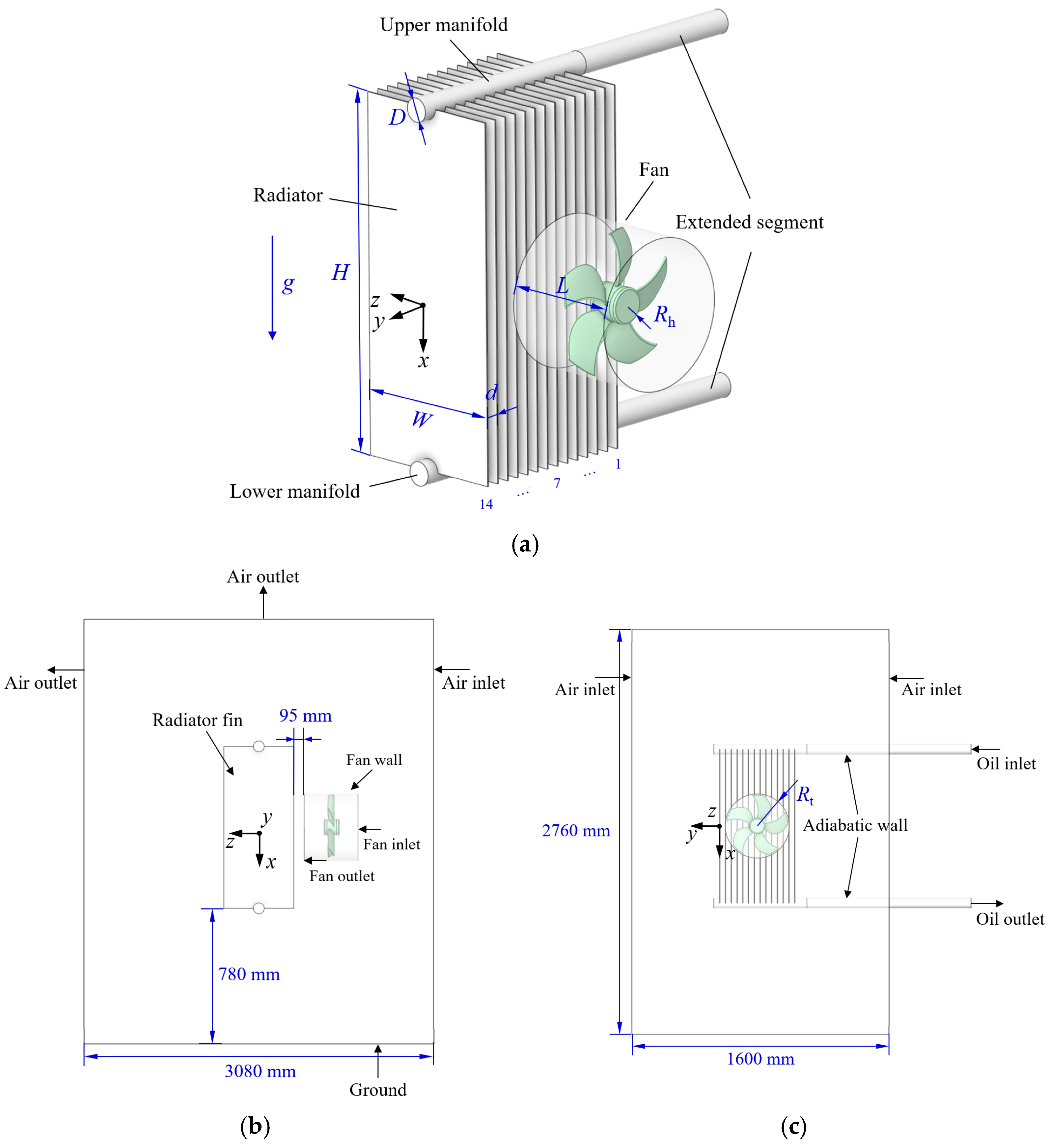
As shown in Figure 2a, a model PC1200-14/520 panel-type radiator is selected for this work. In this figure, the inner diameter (D) of the upper and lower manifolds of the panel-type radiator is 80 mm, the height (H), width (W), and spacing (d) of two adjacent radiator fins are 1200 mm, 520 mm, and 45 mm, respectively. The number of the radiator fins (N) is 14, and the distance of the radiator fins from the ground (h) is 780 mm. To simplify the computation, based on the actual size of the radiator fin being simplified as a rectangular body with a thickness of 3.679 mm, the wall thickness of the radiator fin is 1 mm, and the material is carbon steel. In order to make the model closer to the real conditions, the two manifolds of the panel-type radiator are extended by 10 times the pipe diameter, so the oil flow inside the panel-type radiator can be regarded as a fully developed flow. Radiation heat transfer is neglected since this work focuses on forced convection of panel-type radiators [21]. Figure 2b,c show the geometrical dimensions and boundary conditions of the oil and air domains, respectively. The total computational domain is settled as 3080 mm × 1600 mm × 2760 mm through sensitivity validation.
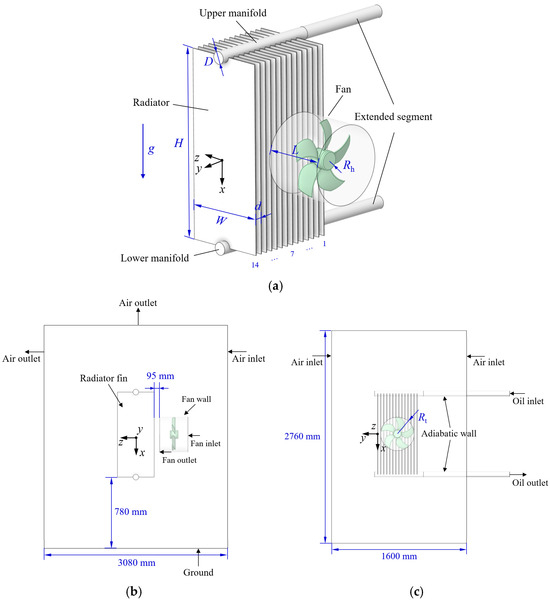
Figure 2.
Schematic of the physical model, computational domain, and its boundary conditions for a panel-type radiator modeled PC1200-14/520 (Case 0 as an example): (a) full model; (b) front view; (c) side view.
In the above figures, some boundary conditions are shown in Table 2. Apart from these, the wall of the fan and the extended segments of the manifolds are set as adiabatic walls, and the inlet and outlet of the fan are set as internal interfaces.
Table 2.
Boundary conditions used for the physical model.
3.2. Governing Equations and Computational Methods
In order to calculate the velocity and temperature field of oil inside the panel-type radiator and the ambient air outside the panel-type radiator, as well as the temperature field distributions inside the radiator fin wall, a 3-D, steady-state, incompressible turbulent flow and heat transfer model is developed [22]. The mass conservation equation, momentum conservation equation, and energy conservation equation for the oil and air domains inside and outside the radiator can be expressed as Equations (2)–(4), respectively. The energy conservation equation for the conduction heat transfer in the solid part of the radiator can be expressed as Equation (5) [23,24]. The shear stress transport (SST) k-ω turbulent model is used in computation [17], where the turbulent equations are given in [25].
where ui and uj are the partial velocities in different directions, m s−1; i and j denote the tensor notation; p is the pressure, Pa; T is the temperature, K; xi is the direction of coordinates, m; ρ is the density of fluid, kg m−3; μ is the dynamic viscosity, kg m−1 s−1; δij is the Kronecker delta; g is the acceleration of gravity, m s−2; β is the thermal expansion coefficient, K−1; T0 is the reference temperature of air, K; λ is the thermal conductivity, W m−1 K−1; cp is the specific heat at constant pressure, J kg−1 K−1; λs is the thermal conductivity of solid, W m−1 K−1.
The viscosity of the insulating oil in the transformer is large, and the flow rate is low (usually <0.5 m/s [26]); the oil-flow pattern can be considered as laminar flow [10]. Therefore, the oil side is labeled as Laminar Zone in Ansys fluent.
According to the literature [12,14,27], in AF mode, not every radiator fin is under forced convection because of the limited size of the fan. This means that only part of the fins work in AF mode, while the other remains in AN mode. Therefore, the Boussinesq assumption is used in the air domain to characterize the effect of buoyancy forces induced by temperature differences. The air reference temperature (T0) is set as 297.74 K, and the thermal expansion coefficient (β) is 0.0035 K−1.
The materials used in the simulation and their thermal parameters are shown in Table 3.
Table 3.
Typical thermal parameters in the simulation [28,29].
This paper focuses on the heat transfer enhancement of different horizontal fan arrangements for the panel-type radiator, and the key to this study is the panel-type radiator. The flow characteristics of the fan are not the focus of this study. Therefore, only the fan outputs airflow with a stable flow rate, and pressure needs to be ensured. In order to increase the speed of calculation while maintaining a high calculation accuracy, the 3D Fan Zones model in Fluent is used to model the fan area in the simulation. Three-Dimensional Fan Zones are fluid cell zones that simulate the effect of axial fans by applying distributed momentum sources in toroid-shaped fluid volumes (that is, a blade-swept volume). The axial (Sa), tangential (St), and radial momentum sources (Sr) applied within the 3D Fan Zones can be represented by Equations (6)–(8), respectively [30], wherein the St represents the momentum applied in a direction tangential to the fan wall; this component can produce a rotational or vortex effect and is used to generate the rotational velocity caused by the fan blades. The Sr represents the momentum applied by the fan in the radial direction, and this component can simulate the effect of airflow outward in the radial direction generated by the fan. The Sa represents the momentum applied in the direction of the main flow of the fan, and this component can simulate the force applied to accelerate or decelerate the fluid in the direction of the main flow.
where pfan(qv,air) is the total pressure across the fan for a given axial flow rate (qv,air), Pa; Wfan is the fan power, W; r is the local radial distance from the fan axis, mm; Ω is the fan operating angular velocity, rad s−1; Rh is the fan hub radius, mm; Rip is the radius of a point on the fan blade based on the inflection point ratio, mm; Rt is the radius of the fan blade tip, mm; c1 is the fan factor; Vϕ is the local tangential velocity, m s−1. In the above, Wfan, Rip, and c1 can be obtained from Equations (9)–(11), respectively [30].
where, exit is the velocity vector of the fan outlet plane, m s−1; exit is the area vector of the fan outlet plane, m2; bip is the fan inflection point ratio.
The pressure rise in the 3D Fan Zone is usually specified as a function of the volumetric flow rate through the fan, and since the fans used in panel-type radiators are all set to operate at rated conditions. So, the total fan pressure is specified as a constant during the simulations in this study [17,18]. The commercial numerical software Fluent 17.2 is used to discretize the governing equations based on the finite volume method (FVM). In order to ensure computational accuracy, the convective terms in the momentum, energy, and turbulence equations are in a second-order upwind scheme. The velocity–pressure is solved using the steady-state COUPLED algorithm. Convergence is achieved by ensuring the final residuals of the computations are less than 10−4. The computational workstation used for the numerical simulation has a clock speed of 2.39 GHz and 256 GB RAM, and the computational time required to accomplish a simulation on eight parallel processors is about 48 h.
3.3. Grid Independence Test
As shown in Figure 3, the polyhedral meshes generated by Fluent meshing are used in numerical simulation. Figure 3a shows the mesh of the 3D-Fan-Zone, and Figure 3b shows the local mesh of the upper manifold and its nearby region. The mesh-refined at smaller geometrical features is set, and the boundary layer is added on both sides of the radiator wall to improve the numerical simulation. A thin prism mesh with a thickness of 0.13 mm near the wall is used for the boundary layer, which can meet the requirements of the SST k-ω turbulence model for the wall mesh ( ≈ 1) [31,32].
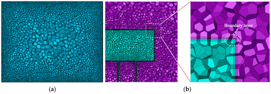
Figure 3.
Computational mesh details: (a) 3D-Fan-Zone mesh; (b) oil and air domain mesh.
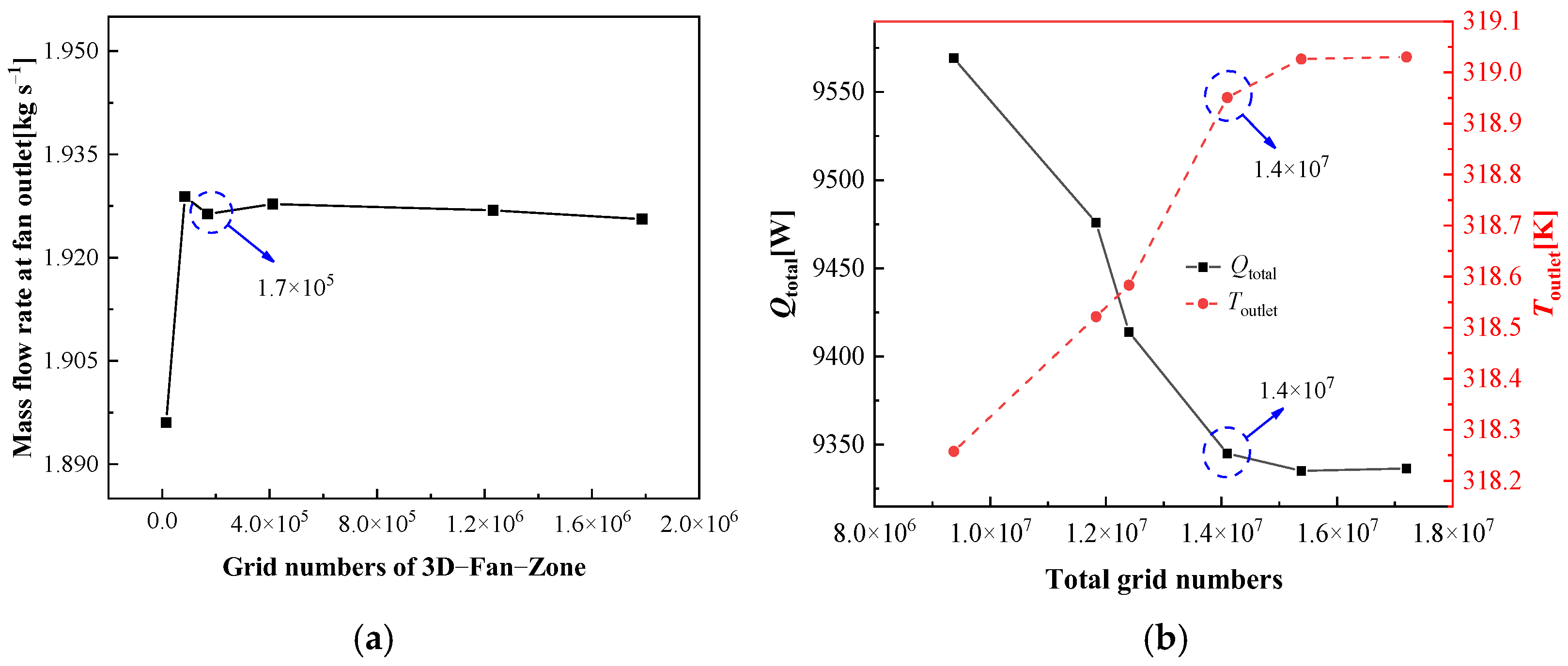
The results of the mesh-independence validation for numerical simulation are shown in Figure 4. Figure 4a shows the variation of mass flow rate at the fan outlet for different grid numbers. When the number of grids reaches 1.7 × 10⁵, the mass flow rate of the high-speed rotating airflow generated by the 3D-Fan-Zone becomes stable. Figure 4b shows the variation of total heat transfer rate (Qtotal) and outlet oil temperature (Toutlet) of the panel-type radiator with different total grid numbers. When the total number of grids reaches 1.4 × 10⁷, Qtotal and Toutlet only change by 0.11% and 0.02%, respectively, even if the number of grids is further increased. Therefore, it can be judged that the numerical results should be independent of the grid when total grid numbers reach 2.24 × 10⁷.
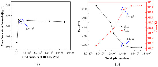
Figure 4.
Computational results for the grid independent test (Case 0, qv,oil = 1.0 m3 h−1): (a) variations of mass flow rate at fan outlet with different regional grid numbers; (b) variations of total heat transfer rate and outlet oil temperature with different total grid numbers.
4. Experimental Test
4.1. Experimental Facility
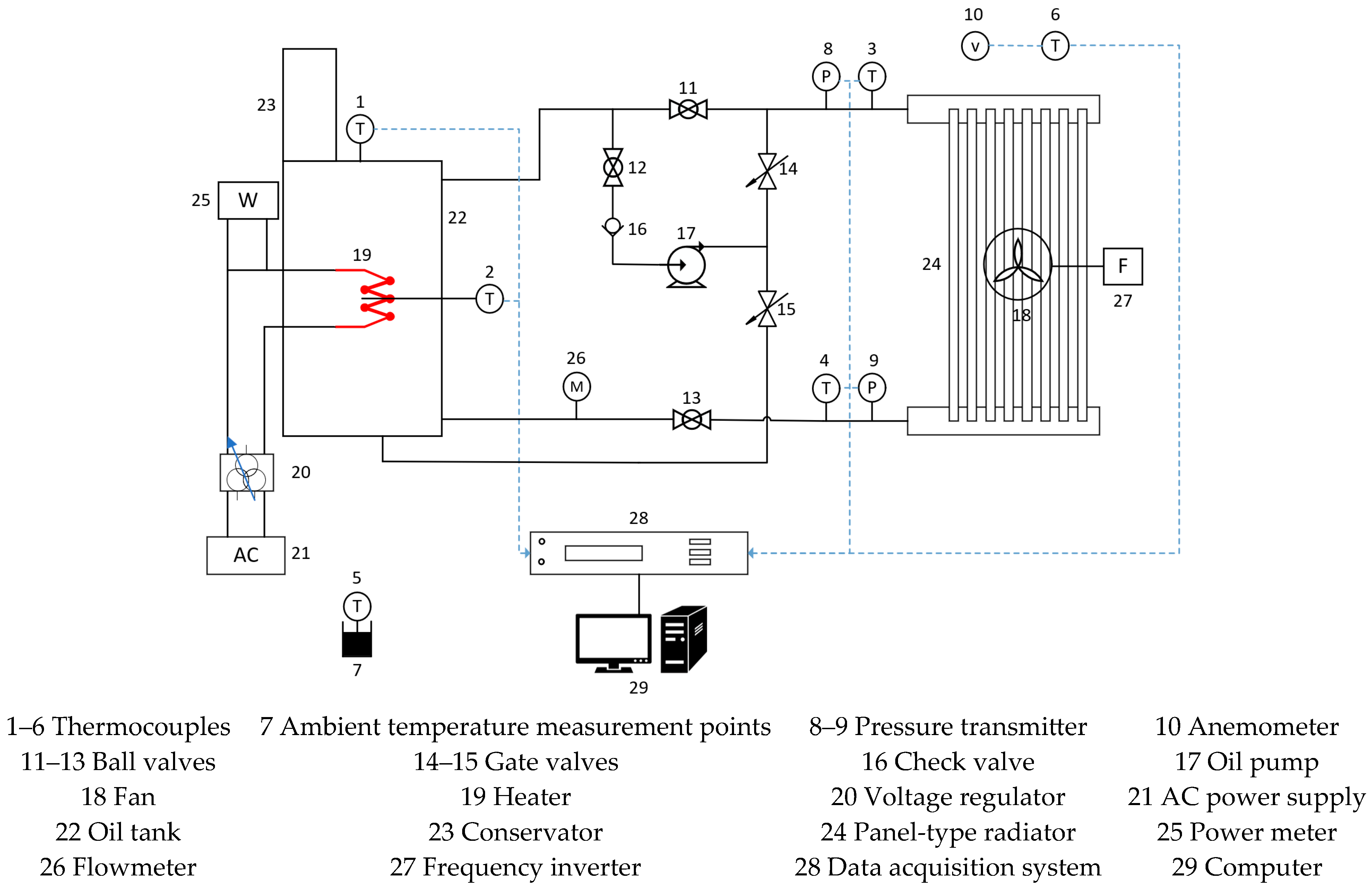
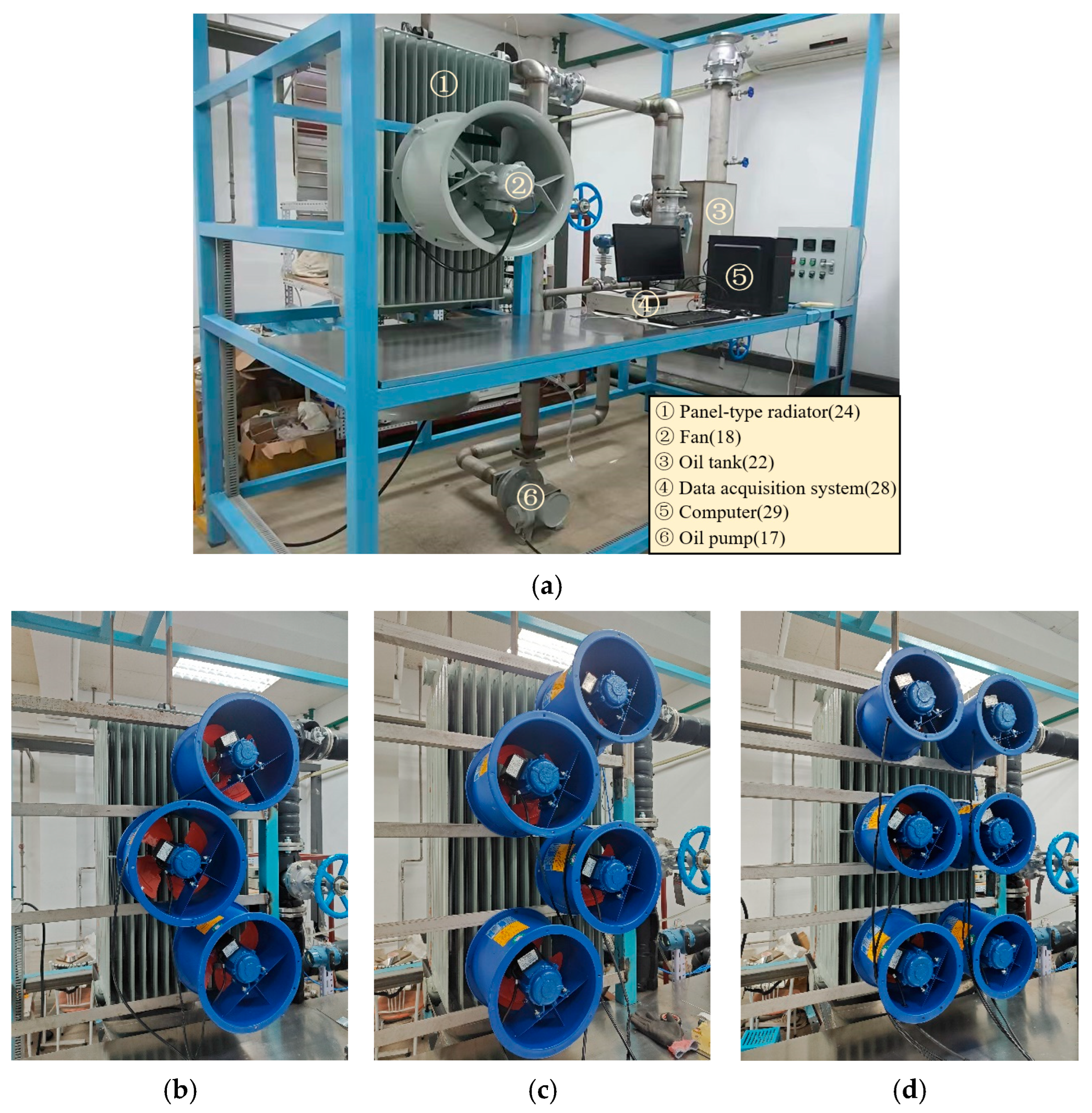
The thermal performance test system of the panel-type radiator in OFAF mode is shown in Figure 5, which mainly includes the panel-type radiator (PC1200-14/520, Shenyang Dongdian Power Equipment Development Co., Ltd., Shenyang, China), the oil circuit system, the fan (Changchun Kehuan Intelligent Control Electrical Equipment Co., Ltd., Changchun, China), and the measurement system. Among them, the oil circuit system mainly consists of pipes, a heater (Xinghua Junhui Electric Heating Appliances Factory, Xinghua, China), an oil pump (Changchun Kehuan Intelligent Control Electrical Equipment Co., Ltd., Changchun, China), and an oil tank; the measurement system mainly consists of thermocouples (DwyerOmega, Michigan City, IN, USA), a flowmeter (Shannxi Shang-tai AIC Co., Ltd., Xi’an, China), a three-phase power meter (CHINT Group Corporation, Leqing, China), and a data acquisition system (Tektronix, Beaverton, OR, USA). The corresponding experimental test platforms of different cases are shown in Figure 6.
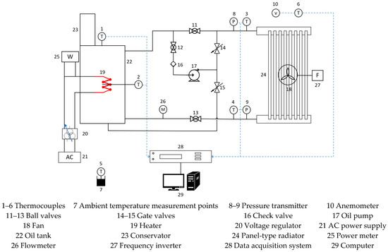
Figure 5.
Experimental system.
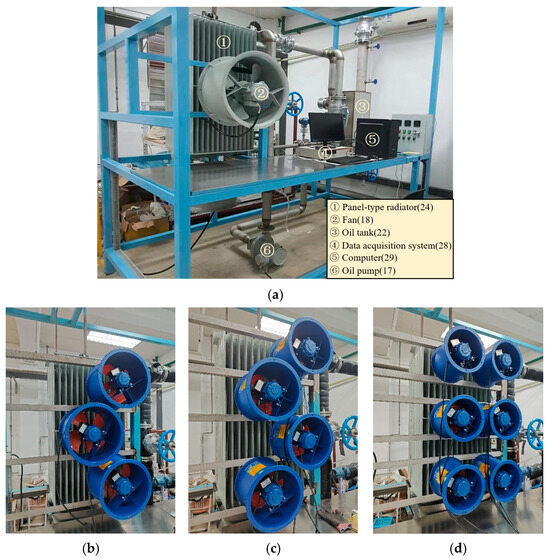
Figure 6.
Experimental test platforms of different cases: (a) Case 0; (b) Case 1; (c) Case 2; (d) Case 3.
Prior to the test, insulating oil (Sinopec Lubricants Co., Ltd., Beijing, China) is filled to the full capacity of the test body and the oil circuit system, and then the test system is left to stand for 2–3 days to eliminate the air mixed into the oil. During the start of the testing, the heater in the oil tank is switched on, while the transformer oil pump is started. Insulating oil is driven by an oil pump drive from the upper manifold into the panel-type radiator; its inlet temperature can be measured by 4 inserted T-type thermocouples. Subsequently, insulating oil driven by pumping pressure flows from top to bottom in the radiator while being cooled by dissipating heat to ambient air. Finally, oil flows back from the bottom manifold to the oil tank, and the circulation loop continues till the steady state is reached. The inserted power of the heater is measured by a three-phase wattmeter, the volumetric oil flow is measured by a target flow meter installed at the outlet of the lower manifold, and the radiator’s surface temperature and ambient temperature are all measured by T-type thermocouples. All above experimental results were recorded at 5 s intervals during the cooling process by means of a data acquisition system (Keithley-2750). The experiment was conducted in a room regulated by an air conditioner with room temperature variations ranging from about 23 to 25 °C. The heating power was continuously adjusted to control the inlet oil temperature (Tinlet) and the ambient temperature (Tair,∞) in order to satisfy Tinlet − Tair,∞ = 40 K [33]. This is performed until the experimental system satisfies Δ|Tinlet − Tair,∞| < 0.2 K within 1 h, at which point the experiment system can be turned off, and the data can be collected.
The resolution and model of measurement instruments used in the experiment are shown in Table 4. The calibration process for the thermocouples is as follows: First, prepare a constant-temperature bath and a high-precision platinum resistance thermometer PT100 (Modelled OMEGA HH370). Next, bind the T-type thermocouples used in this study and the probe of the reference thermometer together using thin copper wire, and immerse them simultaneously into the constant-temperature bath. Then, select three calibration temperature points (0 °C, 50 °C, and 100 °C) within the primary temperature range of interest for this study. Adjust the water temperature in the constant-temperature bath to each calibration point sequentially and record the data through the data acquisition system once the readings from both the thermocouples and the reference thermometer stabilize. Repeat the above process to ensure that the deviations between the 42 temperature sensors used in this study and the reference temperature values at the calibration points are less than 0.5 °C.
Table 4.
The resolution model of measurement instruments.
4.2. Data Reduction and Uncertainty Analysis
When the experimental system reaches a steady state, the input power of the heater (P), the total heat transfer rate of the panel-type radiator (Qtotal), and the heat transfer rate of the pipe and tank (Qs) satisfy the following equation:
The total heat transfer rate (Qtotal) of the panel-type radiator can be given as follows:
where qm,oil is the mass flow rate of oil, kg s−1; cp,oil is the heat capacity of oil, J kg−1 K−1.
The air-side convective heat transfer coefficient (hair) of the radiator is defined as shown in Equation (14).
where Twall,outer is the average temperature of the outer wall surface of the radiator, K; Souter is the outer surface area of the radiator, m2. In this study, Souter = 18.816 m2.
The oil-side convective heat transfer coefficient (hoil) of the radiator can be defined as follows:
where Toil,ave is the average oil temperature, K; Twall,inner is the average temperature of the inner wall surface of the radiator, K; Sinner is the contact area of the oil side, m2. The oil channel is assumed to be uniformly extended to the entire fin in this study, so it can be thought that Sinner = Souter. In addition, Toil,ave can be defined as follows,
while Twall,inner can then be estimated with Fourier’s law:
where δs is the fin wall thickness, m, which is equal to 0.001 m.
According to [34], the total heat transfer coefficient (k) of the radiator can be expressed as Equation (18).
The error comes from the system error, which mainly results from the error of the thermocouples, and the random error, which mainly comes from unstable random factors in this experiment.
For the present experiment, the uncertainty of measured results can be analyzed using Type-B uncertainty evaluations, which are based on the accuracy data of transducers and engineering judgment [35]. According to Equation (13), the total heat transfer rate (Qtotal) is a function of the measured values T and qv,oil. The relative standard uncertainty (Type-B) of Qtotal can then be expressed by using the following equation:
Here, the uncertainty components are mainly evaluated with the corresponding calibrated accuracy of transducers used for measurement. Uniform distribution is assumed for each uncertainty component with coverage factor kcov = 3. The relative uncertainty u′(qv,oil) is evaluated based on the maximum error limit of the flowmeter (1.5%), which showed a uniform distribution, i.e., u′(qv,oil) = 1.5%/3 = 0.5%. Similarly, it can be calculated that u′(T) = 0.72%.
Therefore, based on Equation (19), it can be calculated that u′(Qtotal) is 1.13%. Considering a 95% confidence level for the normal distribution with a coverage factor kcov = 2, the relative expanded uncertainties are then calculated as follows:
Therefore, the relative expanded uncertainty of Qtotal is 2.26%. Similar evaluations can be conducted for hair, hoil, and k, and the obtained relative expanded uncertainties are shown in Table 5.
Table 5.
Relative expanded uncertainty of the main variables.
5. Results and Discussion
5.1. Analysis of Flow and Heat Transfer of the Oil Inside the Panel-Type Radiator
In Figure 7a–f, the velocity distribution and the streamline within the fifth and tenth fins of the panel-type radiator for different inlet oil flow rates (qv,oil) in Case 1 are shown, where the color bands of the streamline diagrams represent the temperature variation of the insulating oil. Notably, the internal insulating oil flow is relatively insensitive to the different fan arrangements; hence, only the oil-side flow details for Case 1 are presented herein. As shown in Figure 7a–f, it can be observed that the velocity boundary layer in the upper manifold is clearly visible at each inlet oil flow rate, and this characteristic is similar to the fully developed pipe flow of laminar flow in a circular tube [36]. This phenomenon is mainly because of the larger dynamic viscosity of the insulating oil and the smaller flow rate (when the inner diameter of the manifold is chosen as the characteristic length, the insulating oil inlet Re at different qv,oil is Re(qv,oil = 1 m3 h−1) = 570.56, Re(qv,oi = 1.3 m3 h−1) = 741.73, Re(qv,oil = 1.6 m3 h−1) = 912.90, Re(qv,oi = 1.9 m3 h−1) = 1084.07, Re(qv,oil = 2.2 m3 h−1) = 1255.24 and Re(qv,oi = 2.5 m3 h−1) = 1426.41, separately, where Re is defined in Equation (21)). As shown in Figure 7a, when insulating oil flows through the connection between the manifold and the first radiator fin, part of the insulating oil flows to the radiator fin, which leads to the destruction of the local flow boundary layer on the inner surface of the manifold, and the rest of the insulating oil continues to flow along the upper manifold. As the insulating oil continues to flow through the remaining heat sink connections, driven by pump pressure and gravity, other insulating oil gradually flows into the radiator fin along the upper manifold. During this progress, the velocity of the oil flow in the upper manifold decreases, and the center of the high-speed region moves downwards. Until the insulating oil flows through the last fin, the remaining insulating oil produces a reflow at the end of the upper manifold. As the insulating oil flows sequentially in radiator fins through the convective heat transfer with the inner wall surface, heat conduction in the fin wall, and convective heat transfer from the outer wall surface to air, its temperature gradually reduces along the height of the radiator. Consequently, the density of the oil also gradually increases due to the inverse relationship between temperature and density. In addition, since the oil flow rate through the same section is constant, the oil flow rate in the lower manifold is significantly reduced compared to the upper one. Finally, when the insulating oil flows into the lower manifold from the radiator fin, the direction of the streamline changes, and the main flow of insulating oil strikes the bottom surface of the lower manifold, which also creates local reflow at each outlet of the fins (as shown in Figure 7c). Comparing Figure 7a–f, as the insulating oil flow rate increases, the velocities in the radiator fin, and the upper and lower manifolds increase, and the oil temperature distribution becomes more uniform.
where ρ is the oil density at the inlet, kg m−3; u is the oil flow rate at the inlet, m s−1; D is the manifold diameter, m; μ is the insulating oil dynamic viscosity, kg m−1 s−1.
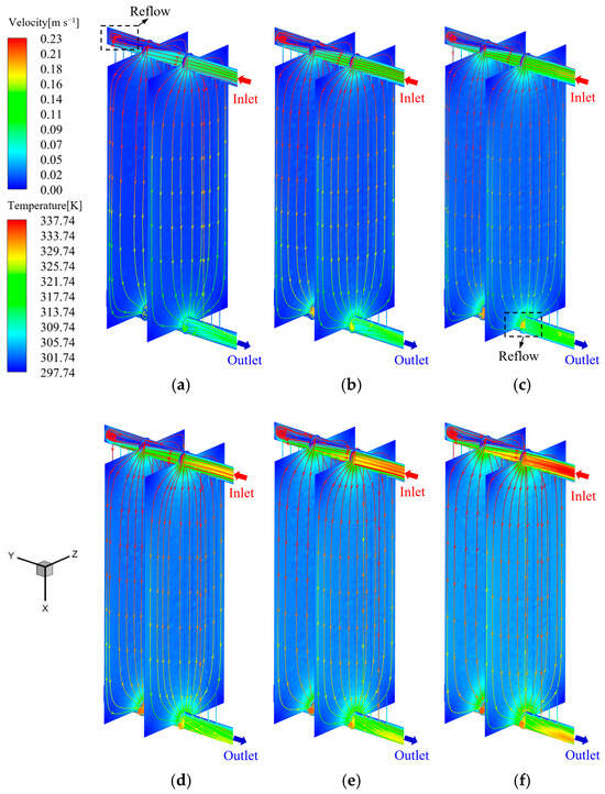
Figure 7.
Velocity distribution contours and streamline colored with the band of oil temperature within the 5th and 10th fins of the panel-type radiator at different qv,oil (Case 1): (a) qv,oil = 1.0 m3 h−1; (b) qv,oil = 1.3 m3 h−1; (c) qv,oil = 1.6 m3 h−1; (d) qv,oil = 1.9 m3 h−1; (e) qv,oil = 2.2 m3 h−1; (f) qv,oil = 2.5 m3 h−1.
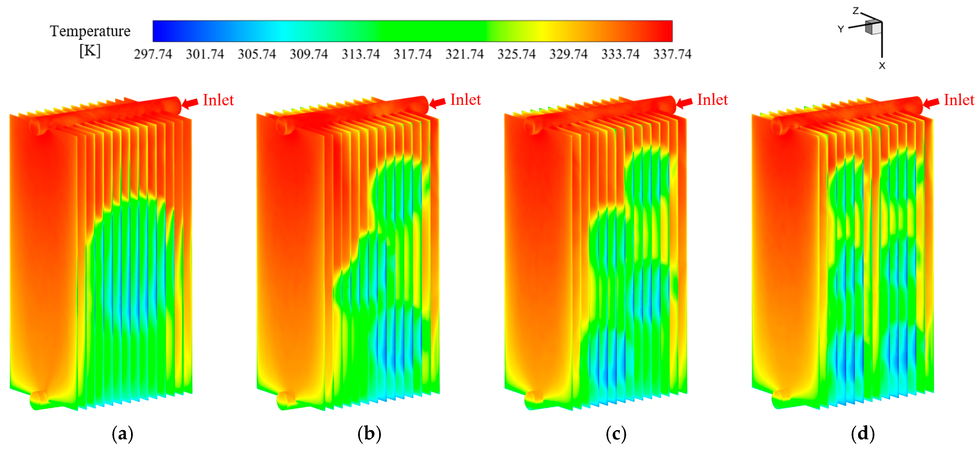
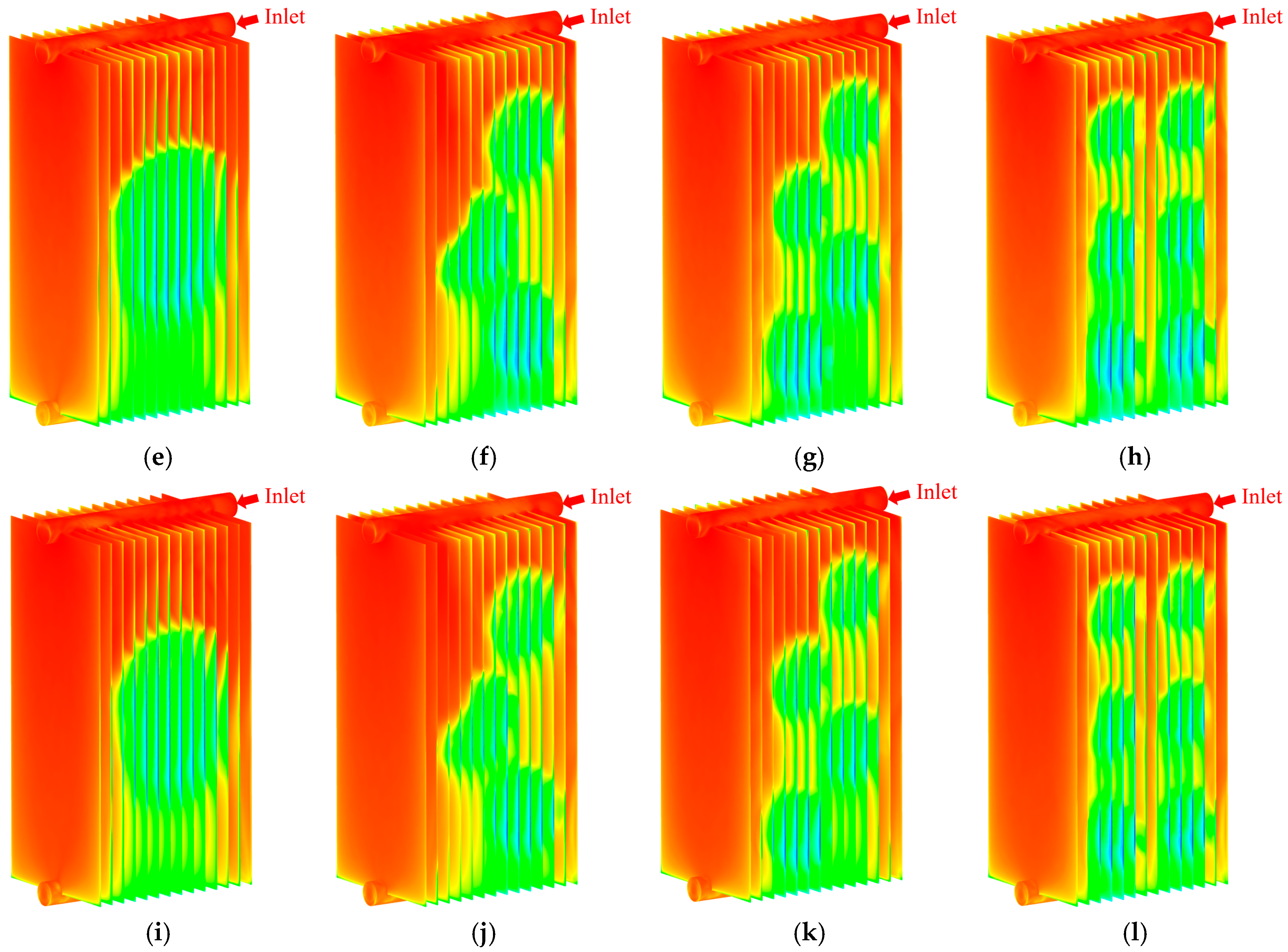
Figure 8a–l show the temperature distribution on the outer wall surface of the radiator fin at different insulating oil flow rates (qv,oil = 1.0 m3 h−1, 1.6 m3 h−1, 2.2 m3 h−1) for Cases 0–3, respectively. From these figures, it can be found that the wall temperature distributions of the first and fourteenth radiator fins for each case are similar to the wall temperature distributions in the literature [37], which works in AN mode. This phenomenon can be attributed to the insufficient coverage of the airflow generated by the fan over the entire fin surface. Consequently, the airflow behavior near the initial and terminal fins approximates that of natural convection. Furthermore, localized low-temperature regions corresponding to the number and location of the fans can be observed under all cases in Figure 8a–l. The tops of these regions are approximately circular in shape, and these regions gradually expand in the positive x-direction of the fin. The aforementioned phenomenon is primarily attributed to the significant reduction in radiator wall temperature at the location directly blown by the fan, which indirectly leads to a decrease in the insulating oil temperature at that location. Furthermore, due to the x-directional flow of the insulating oil, the insulating oil located downward of the low-temperature region absorbs heat from the radiator surface through convective heat transfer, resulting in a decrease in the wall temperature at the radiator surface. A comparison of Figure 8a–d reveals that in Case 0, due to the largest local fan-blowing area, the enhanced heat dissipation region of the fan is more concentrated, resulting in the longest diffusion distance of its localized low-temperature region in the x-direction. In Cases 1–3, as the blowing area of a single fan gradually decreases, the intensified heat dissipation area of the fan becomes more dispersed. Therefore, the diffusion distance of a single local low-temperature zone along the positive x-axis gradually decreases. Meanwhile, due to the increase in fan numbers, the panel-type radiator transitions to zoned heat dissipation at this time. Comparing Figure 8a,e,i, Figure 8b,f,j, Figure 8c,g,k, and Figure 8d,h,l separately, it can be found that as the flow rate of the insulating oil gradually increases, the temperature difference between the inlet and outlet of the heat sink decreases. Moreover, under the same fan arrangement conditions, the diffusion distance of the local low-temperature zone gradually decreases. This is because, at a lower oil velocity, the higher-temperature insulating oil remains in the fan blowing area for a longer time, which allows for a more effective heat dissipation. As the oil flow rate increases, the insulating oil inside the radiator (especially the insulating oil near the leeward region) can not fully dissipate heat before flowing out of the fan coverage region. Subsequently, the lower-temperature insulating oil near the windward region mixes with the higher-temperature insulating oil near the leeward region, causing the wall temperature to rise again. Therefore, in Figure 8, the local low-temperature zone can only diffuse within a limited distance because the insulating oil flowing through the fan coverage region does not have sufficient time to fully dissipate its heat before exiting the region. As the flow rate increases, the residence time of the insulating oil in the fan coverage region decreases, further reducing the diffusion distance.
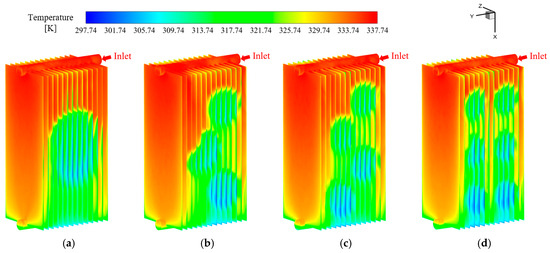
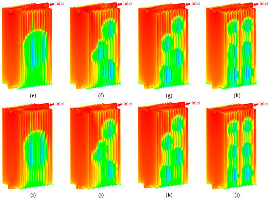
Figure 8.
Temperature distribution on the outside wall surface of the panel-type radiator as the oil flow rate is qv,oil = 1.0, 1.6 and 2.2 m3 h−1, respectively (Cases 0–3): (a) Case 0, qv,oil = 1.0 m3 h−1; (b) Case 1, qv,oil = 1.0 m3 h−1; (c) Case 2, qv,oil = 1.0 m3 h−1; (d) Case 3, qv,oil = 1.0 m3 h−1; (e) Case 0, qv,oil = 1.6 m3 h−1; (f) Case 1, qv,oil = 1.6 m3 h−1; (g) Case 2, qv,oil = 1.6 m3 h−1; (h) Case 3, qv,oil = 1.6 m3 h−1; (i) Case 0, qv,oil = 2.2 m3 h−1; (j) Case 1, qv,oil = 2.2 m3 h−1; (k) Case 2, qv,oil = 2.2 m3 h−1; (l) Case 3, qv,oil = 2.2 m3 h−1.
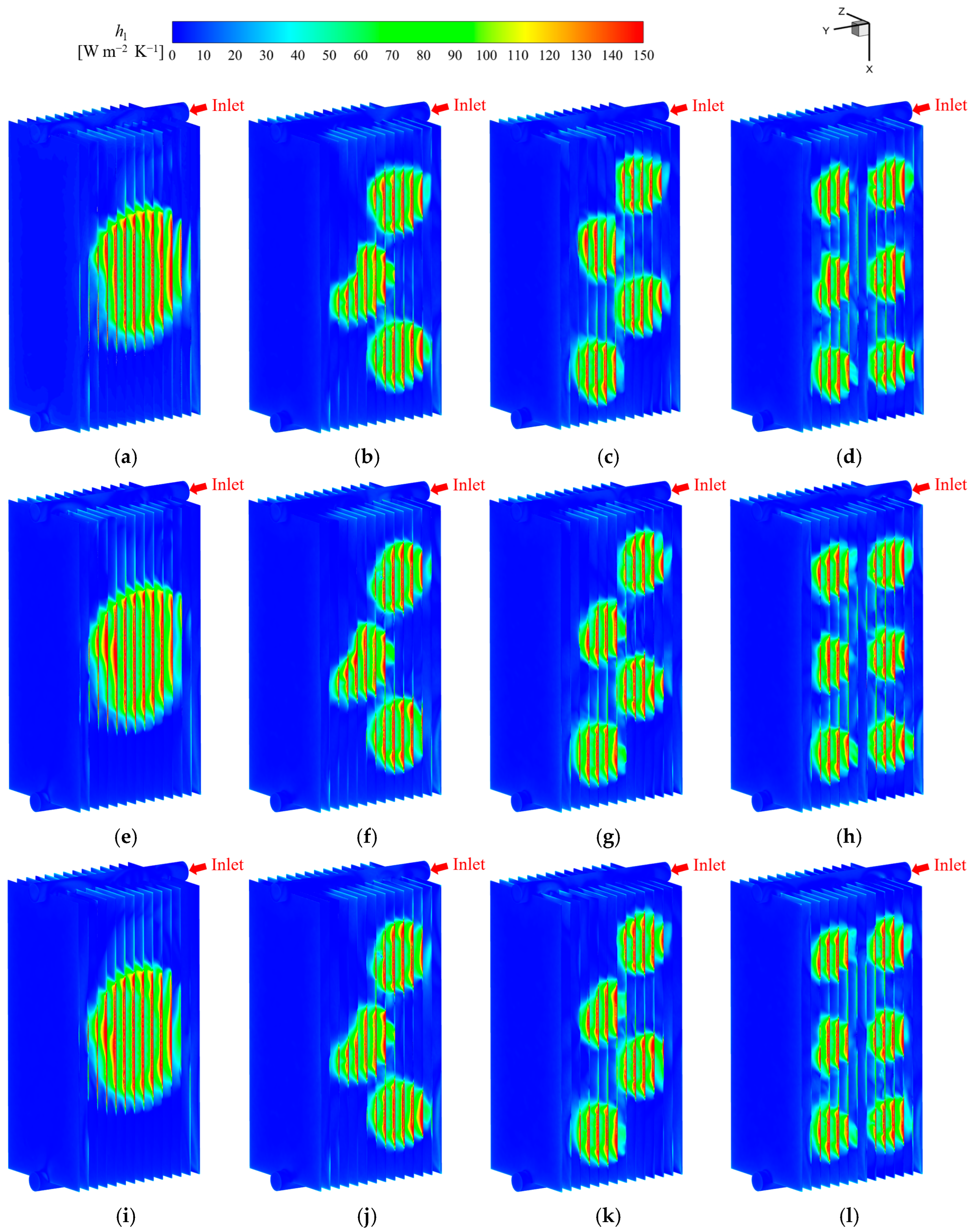
Figure 9a–l show the distribution of the local convective heat transfer coefficient (hl) on the outer wall surface of the radiator fin at different inlet insulating oil flow rates (qv,oil = 1.0 m3 h−1, 1.6 m3 h−1, 2.2 m3 h−1) for Cases 0–3, respectively, where hl can be defined in Equation (22). As shown in Figure 9a–l, there is a local region with a high convective heat transfer coefficient on the windward region of the panel-type radiator that corresponds to the number and location of the fans. Since these regions are directly covered by horizontal blowing fans, it indicates that these side fans enhance heat dissipation in these regions. The area directly covered by the fan (at the lateral of the radiator) is subjected to jet impingement, and the boundary layer is obviously thinned, especially among these regions. Therefore, the local convective heat transfer coefficient at this location is significantly higher than in other surrounding regions. It is worth mentioning that the phenomenon of high heat dissipation performance zones diffusing along the positive x-axis, as observed in Figure 8, can not be observed in Figure 9. This further demonstrates that the diffusion of local low-temperature zones in Figure 8 is not caused by reasons such as the radial diffusion of high-velocity airflow. A comparison of Figure 9a,e,i, Figure 9b,f,j, Figure 9c,g,k, and Figure 9d,h,l reveals that the change in oil flow rate has a relatively small impact on the local convective heat transfer coefficient on the air side of the radiator.
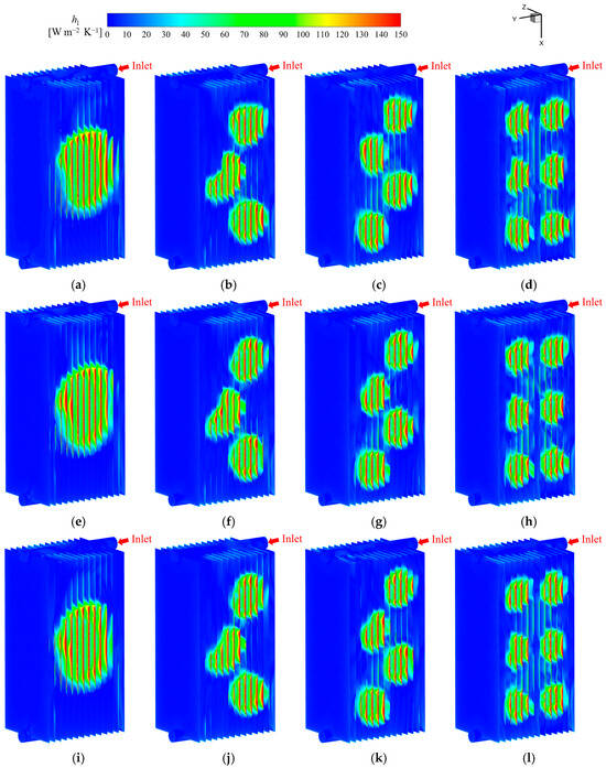
Figure 9.
The distribution of local convective heat transfer coefficient on the outside wall surface of the panel-type radiator as the oil flow rate is qv,oil = 1.0, 1.6 and 2.2 m3 h−1, respectively (Case 0–3): (a) Case 0, qv,oil = 1.0 m3 h−1; (b) Case 1, qv,oil = 1.0 m3 h−1; (c) Case 2, qv,oil = 1.0 m3 h−1; (d) Case 3, qv,oil = 1.0 m3 h−1; (e) Case 0, qv,oil = 1.6 m3 h−1; (f) Case 1, qv,oil = 1.6 m3 h−1; (g) Case 2, qv,oil = 1.6 m3 h−1; (h) Case 3, qv,oil = 1.6 m3 h−1; (i) Case 0, qv,oil = 2.2 m3 h−1; (j) Case 1, qv,oil = 2.2 m3 h−1; (k) Case 2, qv,oil = 2.2 m3 h−1; (l) Case 3, qv,oil = 2.2 m3 h−1.
Furthermore, it is observed that the uniformity of the local low-temperature zone and high heat dissipation performance zone formed by the left fan in Figure 8b,f,j, and Figure 9b,f,j is relatively poor. In order to further elucidate the unique temperature and local convective heat transfer coefficient distributions in Case 1, Figure 10 shows the airflow velocity and static pressure distributions at different yz planes (x = −0.335 m, 0 m, and 0.335 m). As shown in Figure 10a,c, the high-velocity airflow generated by the first and third fans from top to bottom exhibits good symmetry, with the high-velocity main flow zone exhibiting only a minor offset toward the positive y-axis direction at the center. However, in Figure 10b, it is observed that the high-velocity main flow zone of the second fan occurred a significant offset toward the negative y-axis direction relative to its center position. Assuming negligible resistance losses, the sum of dynamic pressure and static pressure along the airflow direction remains constant, according to Bernoulli’s equation; hence, regions with higher flow velocity exhibit lower static pressure. In Case 1, the average velocity is higher and the static pressure is lower at the first and third fans’ locations due to the uneven arrangement of fans. This static pressure difference leads to the main airflow at the outlet of the second fan skewing toward the first and third fans. Correspondingly, in Figure 10e, it is also observed that the static pressure of the airflow to the right of the seventh to eleventh fins gradually decreases. Conversely, it can be found in Figure 10d,f that there is no significant gradient change in static pressure in the air domain between radiator fins.
where ql is the local heat flux rate per unit area, W m−2; Tw is the local wall temperature of the radiator fin, K; and Tair,∞ is the ambient temperature, K.
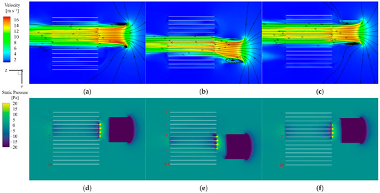
Figure 10.
The velocity and static pressure distribution of air at yz plane (x = −0.335 m, 0 m and 0.335 m, respectively) for Case 1 (qv,oil = 1.0 m3 h−1): (a) velocity distribution at yz plane (x = −0.335 m); (b) velocity distribution at yz plane (x = 0 m); (c) velocity distribution at yz plane (x = 0.335 m); (d) static pressure distribution at yz plane (x = −0.335 m); (e) static pressure distribution at yz plane (x = 0 m); (f) static pressure distribution at yz plane (x = 0.335 m).
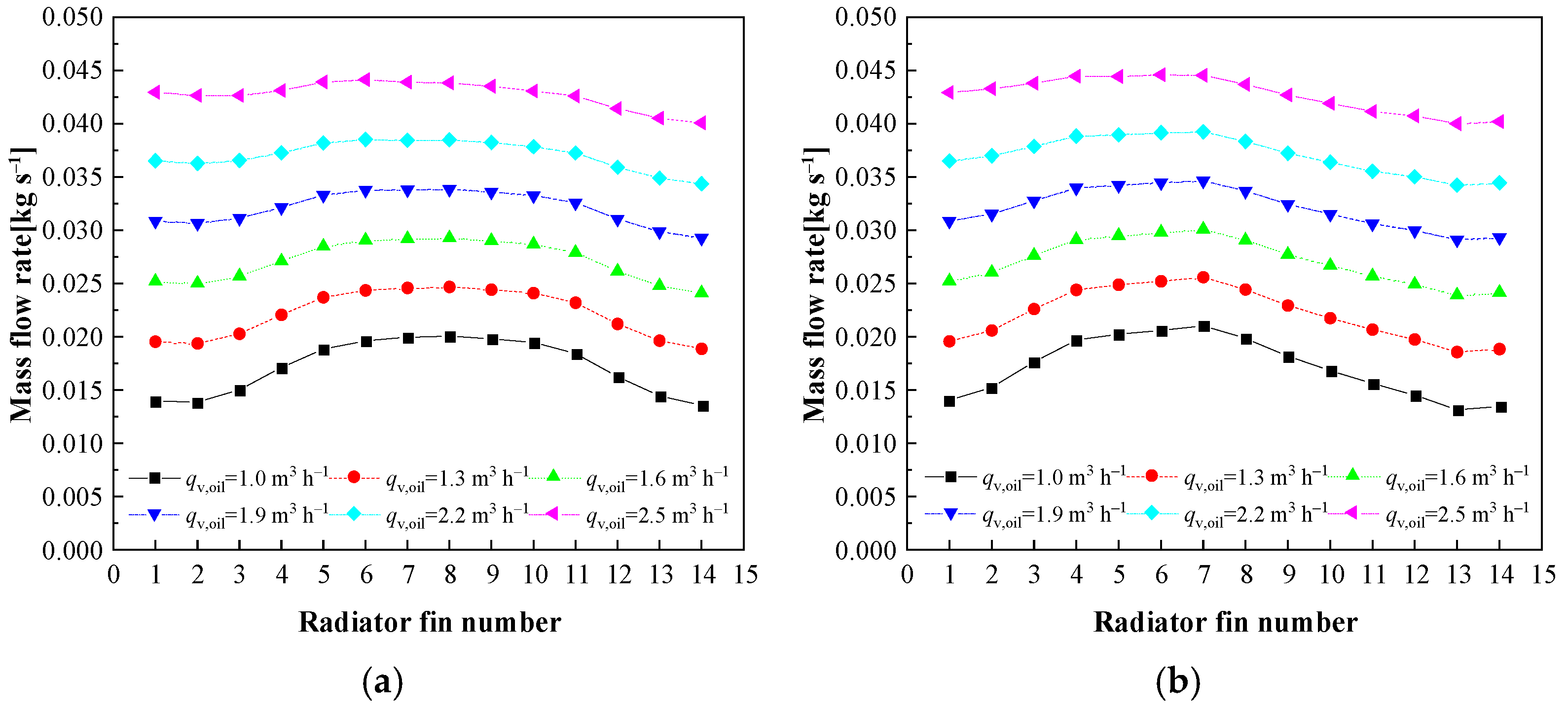
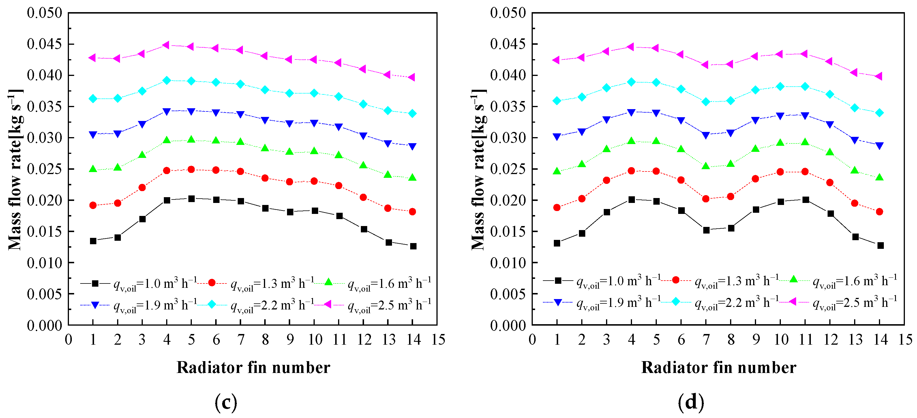
Figure 11a–d illustrate the mass flow rate distribution of the insulating oil within the first to fourteenth radiator fins in different cases (Cases 0–3). For Case 0 (single-fan horizontal blow) in Figure 11a, the insulating oil flow rate within different radiator fins is higher in the middle and lower on both sides over these curves, and the oil flow rate within the fins with smaller numbers is slightly higher than that within the fins with larger numbers. The above phenomenon is due to the fact that in Case 0, the fan is arranged in the center, and the fan mainly covers the third to twelfth fins. Moreover, the fan blowing area gradually decreases as it approaches the sides, and the heat dissipation capacity gradually weakens. Better heat dissipation performance is conducive to reducing the oil temperature inside the radiator panel, thereby increasing the thermosiphon pressure and consequently increasing the oil flow rate of the radiator fins in the middle area [8]. It can also be observed from Figure 11a that the oil flow rate of the fins near the inlet of the manifold (fins 1–7) is slightly higher than that at the other end (fins 8–14). On the one hand, the flow path of the radiator fins near the oil inlet is shorter, the flow resistance is smaller, and the oil flow rate is larger. On the other hand, the fins near the oil inlet are closer to the oil inlet of the upper manifold, the average oil temperature is higher, the total heat dissipation is greater, and the thermosiphon effect is stronger. With the increase in qv,oil, it is observed that the percentage of the oil flow rate inside fins covered by the fan (fins 3–12) decreases. This is because as the qv,oil increases, the pump pressure increases, and the influence of the thermosiphon pressure decreases. Therefore, the oil flow rate distribution within different fins tends to be uniform. In Figure 11b–d, the oil flow rate distribution under different conditions (Cases 1–3) shows significant differences compared to Case 0. In Case 1 (3-fan horizontal blow), due to the non-uniform fan arrangement (two of the fans are located on the side of fins 3–7), these fins have better heat dissipation performance and a larger percentage of oil flow rate distribution. The other fan is mainly located on the side of fins 7–12, so the flow rate of fins 8–12 is higher than that of natural convection but lower than that of fins 3–7, which are directly blown by two fans. Specifically, according to Figure 9b,f,j, the seventh fin is the shared influence area of three fans, so it has the best heat dissipation performance and the largest oil flow rate. As shown in Figure 11c, for Case 2 (4-fan horizontal blow), it can be found that the oil flow rate distribution curves have two local maximum values, with the left local maximum value larger. According to Figure 9c,g,k, on the one hand, the two fans near the oil inlet are located at a higher position, where the insulating oil at this position has a larger temperature difference with the environment, resulting in stronger heat dissipation. On the other hand, the fins with smaller serial numbers are closer to the oil inlet of the manifold, which also leads to enhanced heat dissipation performance. Finally, in Figure 11d, the oil flow rate distribution curves have two highly symmetrical bulges, which are caused by the uniform arrangement of the six fans in Case 3. This also indicates that the asymmetry of the two bulges in Case 2 is mainly caused by the asymmetric arrangement of the fans.
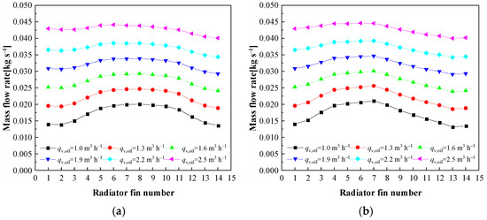
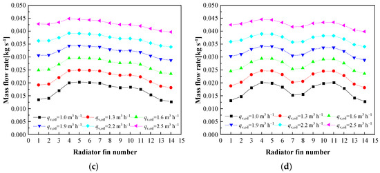
Figure 11.
Distribution of insulating oil mass flow rate in the 1st to 14th radiator fins under different qv,oil in different cases: (a) Case 0; (b) Case 1; (c) Case 2; (d) Case 3.
5.2. Analysis of Flow and Heat Transfer of the Air Outside the Panel-Type Radiator
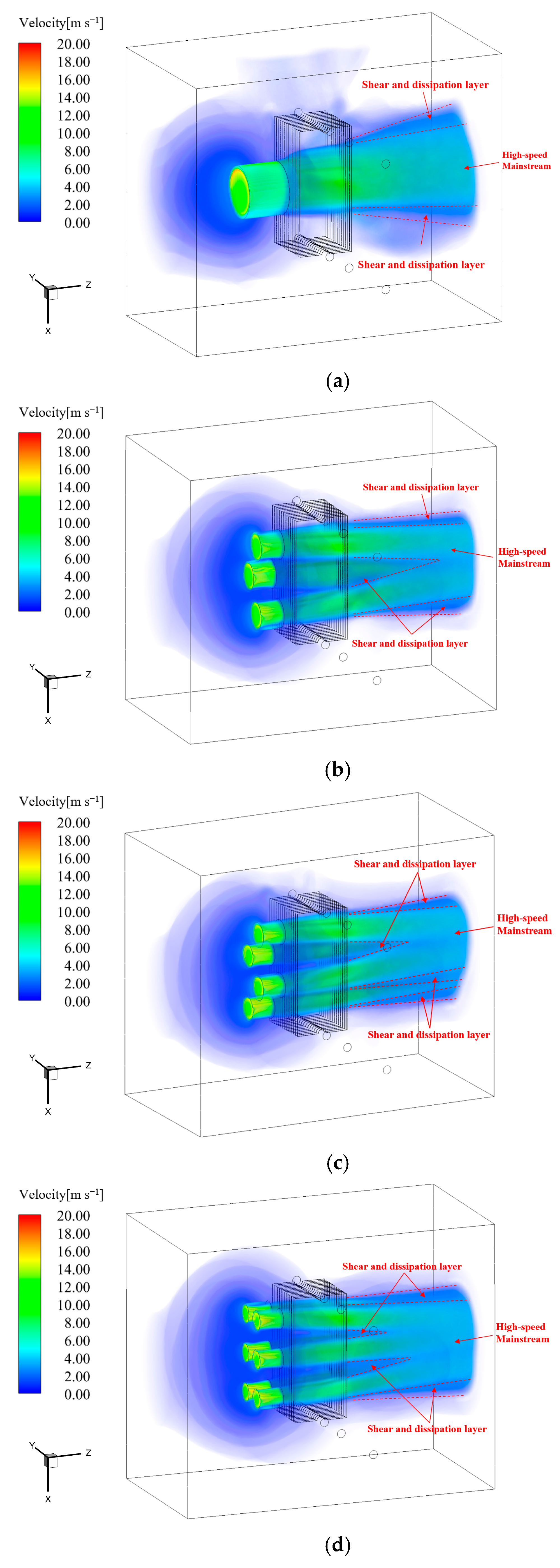
Since different oil-side flow rates have relatively small impacts on the distribution of the air, the operating conditions with oil flow rates of qv,oil = 1.0 m3 h−1 are mainly analyzed and explained in this section. Figure 12a–d show the velocity distribution of the air domain for Cases 0–3 with an oil flow rate of qv,oil = 1.0 m3 h−1, respectively. In Figure 12a (Case 0), the fan sucks in cool airflow from the back and blows it toward the panel-type radiator, which then flows through the air channel between radiator fins and is subsequently discharged from the other side of the panel-type radiator. When the high-speed airflow flows from the fan outlet, on the one hand, it is subjected to viscous forces, and on the other hand, there is a velocity gradient between the high-speed airflow in the central region and the stationary air in the far field. Therefore, a shear dissipation layer is formed at the edge of the high-speed airflow while the airflow in the central region continues to flow along the main flow direction. This also causes the high-speed mainstream region to gradually spread out along the radial direction to form a bell-mouth shape, and the air velocity along the mainstream direction gradually decreases. As shown in Figure 12b–d, the high-speed airflow generated by each fan displays similar flow characteristics before merging with the cooling fins’ air channels under the three multi-fan arrangements. Compared with Case 0 in Figure 12a, the fan influence region is significantly expanded due to the adoption of multi-fan arrangements in Cases 1–3. Additionally, the phenomenon of intermixing of the air shear dissipation layers between close fans can be observed in all three cases, which can facilitate the integration of high-speed mainstream regions and induce the high-speed fluid to converge in the main flow direction. This mutually offsetting energy dissipation in the shear and dissipation layers of different fans helps reduce fan losses, thereby increasing fan performance [38].
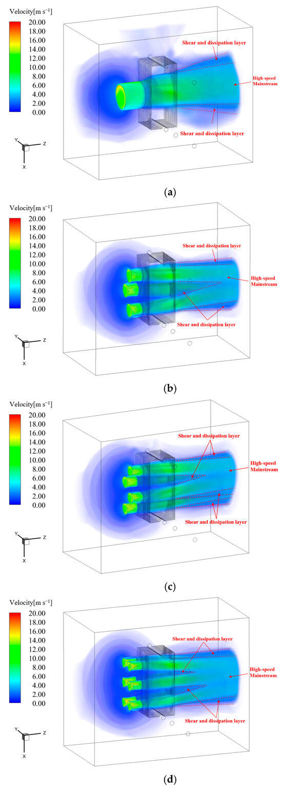
Figure 12.
Distribution of air domain velocity in different cases (qv,oil = 1.0 m3 h−1): (a) Case 0; (b) Case 1; (c) Case 2; (d) Case 3.
As shown in Figure 13a–d, Different temperature distributions on the velocity iso-surfaces corresponding to the velocity values of 4 m s−1 in different cases (qv,oil = 1.0 m3 h−1) are given. It can be clearly found that the air blown by the fans exchange heat with the surface of the radiator fins as it passes through the airflow channel between the fins, resulting in a gradual increase in air temperature. Subsequently, when the air flows out of the channel between the fins, the air temperature gradually decreases and eventually approaches the ambient temperature. Furthermore, it can be observed in Figure 13b–d that the high-speed airflow generated by different fans merges downstream of the main flow, which is consistent with the phenomenon of intermixing of air shear dissipation layers in Figure 12b–d. Finally, a stagnation area along the inner wall of the fans can be observed in Figure 13a–d. This is because of the acceleration of air inside the fans, which, in order to keep a constant mass flow rate, leads to the formation of a local negative pressure region near the fan wall where the shear stress is high.
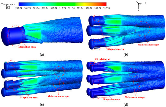
Figure 13.
Air temperature distribution on the velocity iso-surfaces corresponding to the velocity values of 4 m s−1 in different cases (qv,oil = 1.0 m3 h−1): (a) Case 0; (b) Case 1; (c) Case 2; (d) Case 3.
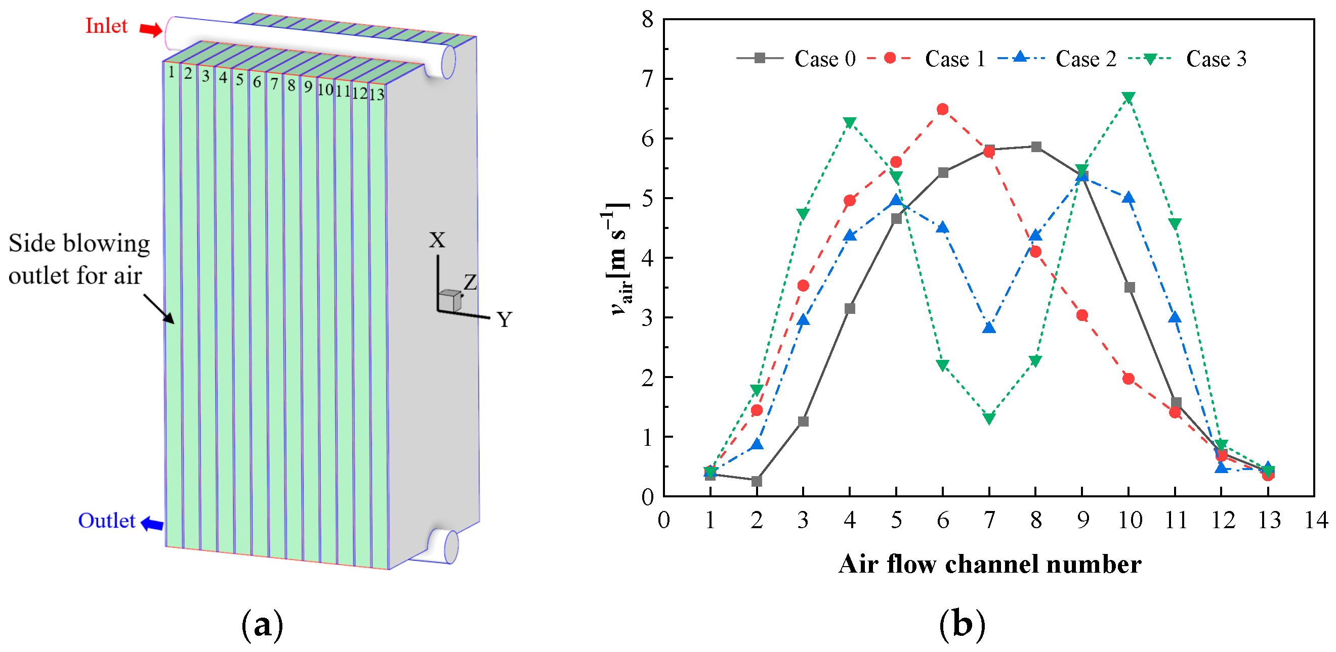
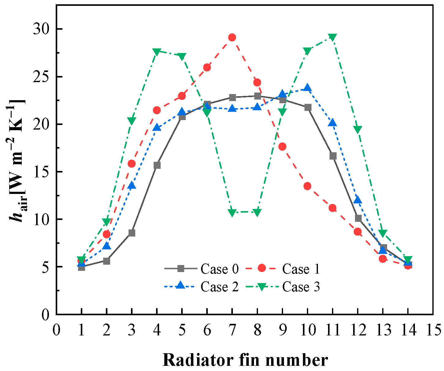
Figure 14a,b present the numbering method of airflow channels and the average outlet air velocity (vair) for different airflow channel numbers in Cases 0–3, respectively. Figure 15 shows the average convection heat transfer coefficients (hair) on the air side of the radiator fins numbered 1–14 in Cases 0–3. As can be seen in Figure 14b, in Case 0 (a single fan horizontal blowing), the airflow generated by the fan mainly flows in airflow channels 3–11. Therefore, the cooling speed of the transformer oil in the corresponding fins is faster in the direct fan blowing region (see Figure 8a,e,i). Accordingly, the hair of radiator fins 3–12 is relatively high in Figure 15, among which the hair of the third and twelfth radiator fins is slightly higher than that of radiator fins not in the direct fan blowing region (radiator fins 1, 2, 13, and 14) because a half of wall surface of these two fins are located in the direct fan blowing region. When the fan arrangement adopts horizontal blowing with three fans (Case 1), as can be seen in Figure 1b, two of the fans are arranged between the second and eighth airflow channels, while the other fan is arranged between the sixth and twelfth airflow channels. Therefore, in Figure 14b, airflow channels 2–11 have a higher average outlet air velocity, while the twelfth airflow channel has a relatively lower air velocity because it can only be blown by the outermost part of a single fan. Because of a larger blowing area near the manifold inlet and outlet, the vair and hair curves shift to the left compared with Case 0. In addition, since the three fans in Case 1 have a larger blowing area for the sixth and seventh airflow channels, then it can be found in Figure 15 that the seventh radiator fin, which is located between the two airflow channels, has the highest hair. As shown in Figure 14b, when the fan arrangement is the horizontal blow with four fans (Case 2), the local maximum values of the average outlet air velocity (vair) at airflow channels 5 and 9 are reached, respectively. As can be seen in Figure 1c, this is because the above two airflow channels are both located in the maximum blowing area of two fans. Additionally, The seventh airflow channel in Figure 14b is the overlapping airflow area of the four fans, but it can be found that the vair of airflow channel 7 is the minimum. This is because this airflow channel is located near the four-fan walls, whose effective blowing area is small. Due to the presence of a flow stagnation area between the fan blade tips and the fan inner wall, as illustrated in Figure 13a–d, the airflow velocity is further reduced. It is noteworthy that in Figure 15, the average heat transfer coefficients (hair) of the fins adjacent to the seventh airflow channel (the seventh and eighth fins) are not significantly lower than those of the other fins. On the one hand, the heat dissipation performance of the seventh and eighth fins is influenced not only by the air velocity within the seventh airflow channel but also by the sixth and eighth channels, which have higher air velocities. On the other hand, although the average air velocity in the seventh airflow channel is relatively low, as observed in Figure 9c,g,k, in Case 2, the airflow from the fan has a broader range of influence along the x-direction, which is beneficial for enhancing the average heat transfer coefficients of the seventh and eighth fins. As shown in Figure 14b, when the fan arrangement is horizontal, blowing with six fans (Case 3), the trend of vair curves is similar to that in Case 2. It also can be found that the local maximum values of vair are located in the fourth and tenth airflow channels. As indicated in Figure 1d, these channels correspond to the largest blowing areas of the three fans. Consequently, the fins near these channels (radiator fins 4, 5, 10, and 11) exhibit better heat dissipation performance with relatively high hair. Conversely, the local minimum value is at the outlet of the seventh airflow channel, which lacks direct blowing and thus has the lowest air velocity. As a result, the fins near this channel (the seventh and eighth fins) demonstrate poorer heat dissipation performance, with lower hair.
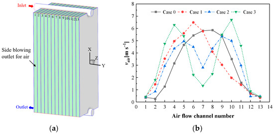
Figure 14.
The variation of average outlet air velocity for different airflow channels in Cases 0–3 (qv,oil = 1.0 m3 h−1): (a) numbers for airflow channels; (b) outlet air velocity for different airflow channels.
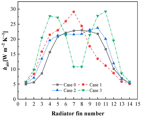
Figure 15.
The average convection heat transfer coefficient (hair) on the air side of the radiator fin for different fin numbers in Cases 0–3 (qv,oil = 1.0 m3 h−1).
5.3. Analysis of Overall Heat Transfer Performance for Panel-Type Radiator
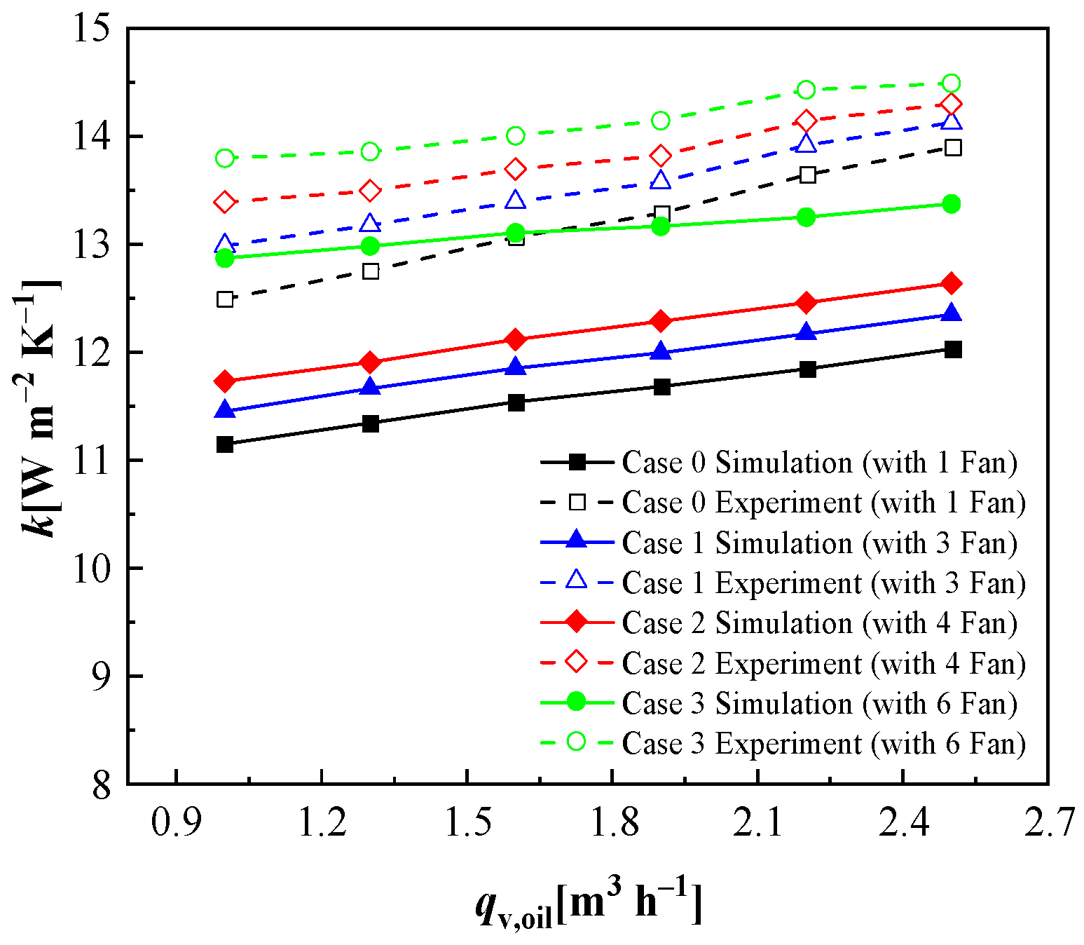
As presented in Figure 16, a comparison between the experimental and numerical results for the overall heat transfer coefficient (k) of the panel-type radiator under different inlet oil flow rates in Cases 0–3 is given. In this figure, the experimental results consistently exceed the numerical simulation results for the same operating conditions. This discrepancy can be attributed, on the one hand, to the simplification in the numerical simulation, where the radiator fins with multiple oil flow channels are modeled as thin rectangular solids, failing to fully capture the detailed flow and heat transfer characteristics inside and outside the fins. On the other hand, a steady-state numerical model for simulating the fan flow is used in this study; it also introduces some computational deviation. Overall, the maximum relative deviation (δmax) and the average relative deviation (δave) between numerical simulation and experiment that can be calculated from Equations (23) and (24) are 13.43% and 10.68%, respectively. This indicates that the simplified numerical method for the air-cooled panel-type radiator proposed in this study maintains a high level of accuracy and preserves a significant amount of local flow and heat transfer details. Furthermore, compared to [8], this study achieves an average reduction in computation time of approximately 90% on a workstation with a lower clock speed and the same number of parallel processors.
where θ is the cases at six different qv,oil, the subscripts sim and exp denote the simulation and experimental results, respectively.
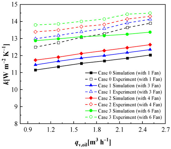
Figure 16.
The variation of overall heat transfer coefficient (k) with inlet oil flow rate in Cases 0–3.
In Figure 16, all of the three multi-fan blows (Cases 1–3) enhance the heat dissipation performance of the panel-type radiator to varying degrees. In the traditional horizontal blow (Case 0), a single fan primarily provides effective cooling to the central section of the fins, while the fins on both ends are nearly subject to natural convection. With the adoption of the multi-fan horizontal blowing method, although the total blowing area is approximately equal, the airflow distribution becomes more uniform. Additionally, the proportion of airflow directed toward the high-temperature region near the header of the fins increases, resulting in improved overall cooling efficiency. According to the experimental results, compared with Case 0, the three multi-fan horizontal blowing methods (Cases 1–3) can improve the overall heat transfer coefficient of the panel-type radiator by up to 3.95%, 7.17%, and 10.42%, respectively; according to the numerical simulation results, the three multi-fan horizontal blowing methods (Cases 1–3) can improve the overall heat transfer coefficient of the panel-type radiator by up to 2.83%, 5.21%, and 15.44%, respectively. In addition, as the oil flow rate increases, the overall heat transfer coefficient of the radiator gradually increases under each fan arrangement. From the previous analysis, on the one hand, this is because the acceleration of the oil flow can effectively reduce the oil-side boundary layer and improve the oil-side convection heat transfer coefficient; on the other hand, it can be known in Figure 8 that the increase in oil flow rate can reduce the oil temperature difference between the inlet and outlet of the radiator, making the average wall temperature of the radiator higher and the distribution more uniform. Since the air-side flow of the radiator is mixed convection, the local natural convection heat dissipation performance can be augmented with the increase in the average wall temperature.
As shown in Figure 16, both the numerical simulation and experiment show that the multi-fan arrangement has a more significant heat transfer enhancement effect at a lower oil flow rate. With the increase in transformer oil flow rate, the heat transfer enhancement effect gradually weakens. This is because the uniformity of the heat sink wall temperature increases with the increase in oil flow rate, and the smaller the benefit of using multiple fans to dissipate heat for the high-temperature area of the radiator. It is foreseeable that as the oil flow rate further increases, the overall temperature of the radiator will tend to become uniform. Under the condition of a constant total blowing area, the enhanced heat transfer effect achieved by the multiple fans will gradually decrease. Therefore, it can be inferred that this method may have a better heat dissipation enhancement effect for panel-type radiators in ON mode with slower oil flow rates. As compared with the minimum oil flow rate (qv,oil = 1 m3 h−1), in the experiment, with the increase in oil flow rate, the four blowing methods (Cases 0–3) can improve the overall heat transfer coefficient by up to 11.22%, 8.76%, 6.81%, and 5.41%, respectively; in the numerical simulation, the four blowing methods (Cases 0–3) can improve the overall heat transfer coefficient by up to 7.88%, 7.85%, 7.72%, and 3.91%, respectively.
6. Conclusions
In this study, the multi-fan horizontal blowing arrangement is used to enhance heat transfer, based on the uniform air distribution and zoned heat dissipation idea, and the flow and heat transfer characteristics inside and outside the radiator in different multiple fan arrangements are investigated. Firstly, the numerical simulation method for the panel-type radiators in AF mode is simplified, and then the simplified numerical method is used to investigate the heat transfer enhancement of the horizontal blowing radiators by multiple fans. Finally, the results obtained from the numerical simulation are compared with those in the experiment. The main conclusions are as follows:
(1) The numerical simulation route for the panel-type radiator in AF mode proposed in this study reasonably simplifies the models for the oil side and air side while retaining most of the details of their flow fields and temperature fields. As compared with findings in the literature, this simplified method can shorten the computational time by about 90% and maintain relatively high accuracy. Within this study, and compared with the experiment, the maximum relative deviation of the simplified method is 13.43%, and the average relative deviation is 10.68%.
(2) Through the traditional horizontal blowing method, only the fins in the middle area of the radiator can be effectively dissipated, while the fins on both ends are nearly subject to natural convection. With the adoption of the multi-fan horizontal blowing scheme, the airflow distribution becomes more uniform, although the total blowing area is approximately equal. Additionally, the proportion of the airflow directed toward the high-temperature region near the header of the fins increases, resulting in improved overall cooling efficiency. As compared with the traditional single-fan horizontal blowing configuration (Case 0), the experiment shows that the three multi-fan horizontal blowing arrangements (Cases 1–3) can increase the overall heat transfer coefficient of the panel-type radiator by up to 3.95%, 7.17%, and 10.42%, respectively. According to the numerical simulation, these multi-fan configurations can increase the overall heat transfer coefficient by up to 2.83%, 5.21%, and 15.44%, respectively.
(3) As the flow rate of the insulating oil increases, the oil side flow accelerates, which, on the one hand, can effectively thin the oil-side boundary layer, enhancing the heat dissipation performance on the oil side. On the other hand, it can reduce the temperature difference between the oil inlet and outlet, leading to a higher and more uniform average wall temperature of the radiator, thus indirectly enhancing natural convection on the air side. Consequently, the overall heat transfer coefficient of the panel-type radiator gradually increases with the oil flow rate for each operating condition. Furthermore, as the insulating oil flow rate increases, the uniformity of the wall temperature of the radiator improves. This reduces the benefits of using multiple fans to cool the high-temperature areas of the radiator, and the augmenting effect of the multi-fan blowing method on heat transfer gradually diminishes. It means that this method may have a better heat dissipation enhancement effect for the panel-type radiator in ON mode with slower oil flow rates. As compared with the minimum oil flow rate (qv,oil = 1 m3 h−1), the experiments show that as the oil flow rate increases, the overall heat transfer coefficient of the radiator can increase by up to 11.22%, 8.76%, 6.81%, and 5.41% for the four blowing methods (Cases 0–3), respectively. According to the numerical simulations, it can increase by up to 7.88%, 7.85%, 7.72%, and 3.91%, respectively.
Author Contributions
G.D.: conceptualization, investigation, writing—original draft preparation; W.S.: methodology, formal analysis; C.F.: conceptualization, formal analysis; H.N.: validation; H.H.: data curation; P.Y.: writing—review and editing; Y.T.: conceptualization, investigation; J.Y.: project administration, funding acquisition, writing—review and editing. All authors have read and agreed to the published version of the manuscript.
Funding
This work was supported by the S &T project of State Grid Shanghai Municipal Electrical Power Company under grant number 52094023000F.
Data Availability Statement
The data will be made available on request.
Conflicts of Interest
Authors Guanxun Diao, Wenrong Si, Chenzhao Fu, Heli Ni and Haimin Hu were employed by the company State Grid Shanghai Municipal Electrical Power Company. Author Peng Yuan was employed by the company Xi’an MaoRong Power Equipment Co., Ltd. The remaining authors declare that the research was conducted in the absence of any commercial or financial relationships that could be construed as a potential conflict of interest.
Nomenclature
| brip | the inflection point ratio |
| cp | specific heat at constant pressure, J kg−1 K−1 |
| D | manifolds diameter, mm |
| d | radiator fin spacing, mm |
| g | gravity acceleration, m s−2 |
| h | convective heat transfer coefficient, W m−2 K−1 |
| H | radiator fin height, mm |
| k | total heat transfer coefficient, W m−2 K−1 |
| L | fan thickness, mm |
| n | number of fans |
| P | heating power, W |
| Q | heat transfer rate, W |
| q | flow rate of transformer oil, m3 h−1 |
| ql | heat flux, W m−2 |
| Rh | radius of fan hub, mm |
| Rip | radius of a point on the fan blade based on the inflection point ratio, mm |
| Rt | radius of fan blade tip, mm |
| r | local radial distance from the fan axis, mm |
| S | area, m2 |
| Sa | axial momentum source, kg m s−1 |
| Sr | radial momentum source, kg m s−1 |
| St | tangential momentum source, kg m s−1 |
| T | temperature, K |
| u | velocity component, m s−1 |
| Vϕ | local tangential velocity, m s−1 |
| v | average air velocity, m s−1 |
| W | radiator fin width, mm |
| x, y, z | cartesian coordinates, mm |
| y+ | dimensionless wall distance |
Greek Letters
| β | thermal expansion coefficient, K−1 |
| δ | deviation |
| δij | kronecker delta |
| λ | thermal conductivity, W m−1 K−1 |
| μ | dynamic viscosity, kg m−1 s−1 |
| π | circular ratio |
| ρ | density, kg m−3 |
| ω | rotation speed, rev min−1 |
| Ω | fan operating angular velocity, rad s−1 |
Subscripts
| air | air |
| ave | average |
| exp | experiment |
| fan | fan |
| h | fan hub |
| i,j | different dimensions of tensor |
| l | local |
| m | mass |
| max | maximum |
| oil | oil |
| s | solid |
| sim | simulation |
| t | fan blade tip |
| v | volumetric |
| ∞ | ambient |
Abbreviations
| AF | air forced cooling |
| AN | air natural cooling |
| FEM | finite element method |
| FVM | finite volume method |
| OD | oil directed cooling |
| OF | oil forced cooling |
| ON | oil natural cooling |
| Re | Reynolds number |
| SST | shear stress transport |
References
- Taghikhani, Z.; Taghikhani, M.A.; Gharehpetian, G.B. A comprehensive investigation on the efficiency of alumina nanoparticles in ONAN and OFAN cooling performance enhancement of transformers. Powder Technol. 2021, 387, 466–480. [Google Scholar] [CrossRef]
- Dejan, S.; Jussi, P.; Matti, L.; Markku, H. Temperature rises in an OFAF transformer at OFAN cooling mode in service. IEEE Trans. Power Deliv. 2005, 20, 2517–2525. [Google Scholar]
- Zhang, L.; Sun, Z.Y.; Li, R.; Liu, M. Numerical simulation of temperature field in radiator for oil-immersed power transformer. In Proceedings of the 18th Annual Conference of China Electrotechnical Society (ACCES 2024), Nanchang, China, 15–17 September 2024; pp. 779–788. [Google Scholar]
- Cha, C.H.; Kim, J.K.; Kweon, K.Y. Investigation of the thermal head effect in a power transformer. In Proceedings of the Transmission & Distribution Conference & Exposition: Asia and Pacific, Seoul, Republic of Korea, 26–30 October 2009. [Google Scholar]
- Dorella, J.J.; Storti, B.A.; Rodriguez, G.A.R.; Storti, M.A. Enhancing heat transfer in power transformer radiators via thermo-fluid dynamic analysis with periodic thermal boundary conditions. Int. J. Heat Mass Transfer. 2024, 222, 125142. [Google Scholar] [CrossRef]
- Nabati, H.; Mahmoudi, J.; Ehteram, A. Heat transfer and fluid flow analysis of power transformer’s cooling system using CFD approach. Chem. Prod. Process Model. 2009, 4, 43. [Google Scholar] [CrossRef]
- Janic, Z.; Gavrilov, N.; Roketinec, I. Influence of cooling management to transformer efficiency and ageing. Energies 2023, 16, 4626. [Google Scholar] [CrossRef]
- Paramane, S.B.; Veken, W.V.; Sharma, A. A coupled internal-external flow and conjugate heat transfer simulations and experiments on radiators of a transformer. Appl. Therm. Eng. 2016, 103, 961–970. [Google Scholar] [CrossRef]
- Paramane, S.B. Flow and temperature visualization over radiators of transformer using experimental and advanced CFD simulations. In Proceedings of the International Conference on Advances in Thermal Systems, Materials and Design Engineering (ATSMDE 2017), Mumbai, India, 21–22 December 2017. [Google Scholar]
- Kim, Y.J.; Ha, M.Y. A study on the performance of different radiator cooling systems in large-scale electric power transformer. J. Mech. Sci. Technol. 2017, 31, 3317–3328. [Google Scholar] [CrossRef]
- Taghikhani, M.A.; Afshar, M.R. Fans arrangement analysis in oil forced air natural cooling method of power transformer radiator. Proc. Inst. Mech. Eng. Part A J. Power Energy 2020, 235, 904–913. [Google Scholar] [CrossRef]
- Garelli, L.; Rodriguez, G.R.; Storti, M.; Granata, D.; Amadei, M.; Rossetti, M. Reduced model for the thermo-fluid dynamic analysis of a power transformer radiator working in ONAF mode. Appl. Therm. Eng. 2017, 124, 855–864. [Google Scholar] [CrossRef]
- Wang, L.J.; Zuo, W.W.; Yang, Z.X.; Cai, Z.L.; Ma, P.X.; Ye, Z.H. CFD-based heat dissipation efficiency monitoring for radiator in different air-cooling modes. In Proceedings of the 5th International Conference on System Reliability and Safety (ICSRS 2021), Palermo, Italy, 24–26 November 2021; pp. 155–160. [Google Scholar]
- Wang, L.J.; Zuo, W.W.; Yang, Z.X.; Zhang, J.W.; Cai, Z.L. A method for fans’ potential malfunction detection of ONAF transformer using top-oil temperature monitoring. IEEE Access 2021, 9, 129881–129889. [Google Scholar] [CrossRef]
- Paramane, S.B.; Joshi, K.; Veken, W.V.D.; Sharma, A. CFD study on thermal performance of radiators in a power transformer: Effect of blowing direction and offset of fans. IEEE Trans. Power Deliv. 2014, 29, 2596–2604. [Google Scholar] [CrossRef]
- Paramane, S.B.; Veken, W.V.D.; Sharma, A.; Coddé, J. Effect of fan arrangement and air flow direction on thermal performance of radiators in a power transformer. J. Power. Technol. 2017, 97, 127–134. [Google Scholar]
- Kim, Y.J.; Jeong, M.; Park, Y.G.; Ha, M.Y. A numerical study of the effect of a hybrid cooling system on the cooling performance of a large power transformer. Appl. Therm. Eng. 2018, 136, 275–286. [Google Scholar] [CrossRef]
- Yun, J.H.; Lee, J.C.; Kang, T.W.; Lee, M.J.; Jeon, J.S.; Yang, H.I. Analysis of radiator cooling effects according to the vertical-horizontal fan arrangement. J. Korean Soc. Manuf. Technol. Eng. 2021, 30, 487–494. [Google Scholar]
- Fdhila, R.B.; Kranenborg, J.; Laneryd, T.; Olsson, C.O.; Samuelsson, B. Thermal modeling of power transformer radiators using a porous medium based CFD approach. In Proceedings of the 2nd International Conference on Computational Methods for Thermal Problems (THERMACOMP 2011), Dalian, China, 5–7 September 2011; pp. 1–4. [Google Scholar]
- Veken, W.V.D.; Paramane, S.B.; Mertens, R.; Chandak, V.; Coddé, J. Increased efficiency of thermal calculations via the development of a full thermo hydraulic radiator model. IEEE Trans. Power Deliv. 2015, 31, 1473–1481. [Google Scholar] [CrossRef]
- Kim, N.H.; Cho, J.P. Air-side performance of louver-finned flat aluminum heat exchangers at a low velocity region. Heat Mass Trans. 2007, 44, 1127–1139. [Google Scholar] [CrossRef]
- Dassi, L.; Chatterton, S.; Parenti, P.; Pennacchi, P. Gyroid lattice heat exchangers: Comparative analysis on thermo-fluid dynamic performances. Machines 2024, 12, 922. [Google Scholar] [CrossRef]
- Koca, A.; Senturk, O.; Çolak, A.B.; Bacak, A.; Dalkilic, A.S. Artificial neural network-based cooling capacity estimation of various radiator configurations for power transformers operated in ONAN mode. Therm. Sci. Eng. Prog. 2024, 50, 102515. [Google Scholar] [CrossRef]
- Koca, A.; Senturk, O.; Akbal, Ö.; Özcan, H. Techno-economic optimization of radiator configurations in power transformer cooling. Designs 2024, 8, 15. [Google Scholar] [CrossRef]
- Menter, F.R. Two-equation eddy-viscosity turbulence models for engineering applications. AIAA J. 1994, 32, 1598–1605. [Google Scholar] [CrossRef]
- Daghrah, M.; Zhang, X.; Wang, Z.D.; Liu, Q.; Jarman, P.; David, W. Flow and temperature distributions in a disc type winding-part I: Forced and directed cooling modes. Appl. Therm. Eng. 2020, 165, 114653. [Google Scholar]
- Li, Y.G.; Zhou, Z.R.; Lin, B.R.; Zhang, H.; Huo, W.F.; Deng, H.L.; Liu, G. Analysis of external heat dissipation enhancement of oil-immersed transformer based on falling film measure. Therm. Sci. 2022, 26, 4519–4533. [Google Scholar] [CrossRef]
- Kim, M.G.; Cho, S.M.; Kim, J.K. Prediction and evaluation of the cooling performance of radiators used in oil-filled power transformer applications with non-direct and direct-oil-forced flow. Exp. Therm. Fluid Sci. 2013, 44, 392–397. [Google Scholar]
- Tao, W.Q. Heat Transfer, 5th ed.; Higher Education Press: Beijing, China, 2019; pp. 254–257. [Google Scholar]
- ANSYS Fluent User’s Guide; Fluent Inc.: Lebanon, NH, USA, 2012.
- Garelli, L.; Rodriguez, G.R.; Dorella, J.J.; Storti, M.A. Heat transfer enhancement in panel type radiators using delta-wing vortex generators. Int. J. Therm. Sci. 2019, 137, 64–74. [Google Scholar] [CrossRef]
- Li, M.L.; Yang, K.; Wang, H.S.; Yu, R.G.; Tong, J.Z. Effect of baffle on heat transfer performance of turbine blade composite cooling channel based on latticework. Machines 2025, 13, 177. [Google Scholar] [CrossRef]
- Panel-Type Radiators for Transformers; Ministry of Industry and Information Technology of the People’s Republic of China: Beijing, China, 2013.
- Radakovic, Z.; Sorgic, M. Basics of detailed thermal-hydraulic model for thermal design of oil power transformers. IEEE Trans. Power Deliv. 2010, 25, 790–802. [Google Scholar] [CrossRef]
- ISO/IEC Guide 98-3; Uncertainty of Measurement-Part 3: Guide to the Expression of Uncertainty in Measurement (GUM-1995). ISO: Geneva, Switzerland, 2008.
- Schlichting, H.; Gersten, K. Boundary Layer Theory, 8th ed.; Springer: Berlin/Heidelberg, Germany, 2000. [Google Scholar]
- Rodriguez, G.R.; Garelli, L.; Storti, M.; Granata, D.; Amadei, M.; Rossetti, M. Numerical and experimental thermo-fluid dynamic analysis of a power transformer working in ONAN mode. Appl. Therm. Eng. 2017, 112, 1271–1280. [Google Scholar]
- Hu, L.B. Design and Simulation of Aerodynamic Noise of Fan; China Machine Press: Beijing, China, 2021. [Google Scholar]


Disclaimer/Publisher’s Note: The statements, opinions and data contained in all publications are solely those of the individual author(s) and contributor(s) and not of MDPI and/or the editor(s). MDPI and/or the editor(s) disclaim responsibility for any injury to people or property resulting from any ideas, methods, instructions or products referred to in the content. |
© 2025 by the authors. Licensee MDPI, Basel, Switzerland. This article is an open access article distributed under the terms and conditions of the Creative Commons Attribution (CC BY) license (https://creativecommons.org/licenses/by/4.0/).