Abstract
Traditional design and shaping methods of helical gears may have difficulties in meeting the requirements of multiple performance indicators simultaneously, such as tooth surface accuracy, load-carrying capacity, and transmission efficiency. This study attempts to overcome these limitations through a multi-objective optimization method and achieve the comprehensive optimization of multiple performance indicators. This paper aims to boost gear system power transmission and cut vibration and noise. It assesses gear shaping impacts via normal load per unit length of the helical gear surface and gear vibration amplitude. Traditional gear shaping schemes were first determined using classic theories and formulas. Then, an improved genetic algorithm was applied to seek optimal helical gear shaping parameters. An eight-degree-of-freedom lumped mass model of the helical gear transmission system, considering bending–torsion–axial coupling, was developed based on Newton’s second law and solved via the fourth-order Runge–Kutta method. Comparisons showed that the traditional shaping scheme reduced the maximum normal load per unit length by 20.6% and the system’s vibration amplitude by 18.3%. In contrast, the improved genetic algorithm achieved greater reductions of 26.34% and 27.2%, respectively. Both methods effectively decreased the maximum normal load per unit length and system vibration amplitude, with the improved genetic algorithm yielding superior results. This work offers a key theoretical basis and reference for enhancing load transmission, reducing costs, and mitigating vibration and noise in gear transmission systems.
1. Introduction
Traditional design and shaping methods of helical gears may have difficulties in meeting the requirements of multiple performance indicators simultaneously, such as tooth surface accuracy, load-carrying capacity, and transmission efficiency. Helical gear shaping is a critical process in mechanical systems, significantly enhancing the performance and durability of gear transmissions. With the rapid advancement of high-end equipment industries, helical gears have found increasingly widespread applications due to their unique advantages. However, during the meshing process, helical gear pairs inevitably generate vibration and noise, and sometimes even experience uneven load distribution, which significantly limits their application in high-precision equipment. To address these issues, gear modification techniques have emerged [1,2]. By appropriately machining the gear tooth surfaces and removing corresponding material, these methods can significantly reduce meshing vibrations in helical gear systems and make the load distribution on the tooth surfaces more uniform. These techniques have been widely studied and applied in fields such as aviation and marine engineering [3,4,5,6]. The primary motivation for this research is to address the significant challenges of vibration and noise reduction in helical gear systems. Despite the widespread use of gear modification techniques, there remains a critical need for more effective methods that can simultaneously optimize both the normal load per unit length and the vibration amplitude of gear transmission systems. This dual optimization is essential for enhancing the overall performance and efficiency of mechanical systems while reducing operational costs and noise pollution.
The conventional genetic algorithm may have problems such as slow convergence speed and a tendency to get trapped in local optima when dealing with complex multi-objective optimization problems. Many scholars internationally have conducted research and analysis on gear modification. In 2012, Baglioni et al. [7] used the tooth top modification method to explore the impact of modification on spur gear efficiency, but the study was limited to spur gears and did not consider nonlinear factors. In 2014, Chen et al. [8] conducted a dynamic analysis of face gear drive systems, taking into account time-varying meshing stiffness and backlash, and derived the influence of modification on the dynamic response of face gear systems, though their focus was on face gears and the model is complex. In 2016, Motahar et al. [9] applied genetic algorithm optimization to bevel gears with the aim of minimizing static and dynamic transmission errors, comparing the dynamic characteristic changes after modification, but their study was limited to bevel gears and had a high computational cost. In 2017, Ni et al. [10] used a numerical design method to study the effect of parabolic modification on the contact path, contact ratio, and meshing performance of crossed helical gears, but they did not analyze dynamic performance. In 2019, Jia et al. [11] developed a housing–transmission coupled dynamic model for multi-stage gear systems and obtained three optimal elements of tooth profile modification through three iterations, although the model assumptions were somewhat idealized. In 2022, Zou et al. [12] proposed an improved algorithm for double-enveloping gear surface topology modification based on overlap ratio, verifying the superiority of the modified gears from both static and dynamic perspectives, but the application scope was limited. In 2024, Zhou et al. [13] proposed a two-stage tooth profile modification curve based on sensitivity parameters, demonstrating its effectiveness in reducing gear transmission error fluctuations, but it had high parameter sensitivity requirements. Han et al. [14] developed a new method for high-contact-ratio gear modification based on transmission error, using a slicing approach to reduce vibration and noise, but manufacturing errors were not fully considered. Autiero et al. [15] found ways to improve gear transmission smoothness by analyzing the impact of modification on meshing stiffness and transmission error, but their study mainly focused on spur gears. In 2025, Li et al. [16] studied hourglass-shaped worm gears, deriving a mathematical model for microscopic meshing performance based on the local conjugacy of improved involutes and investigating the effects of different modification positions on worm gear performance, but the model was complex and had a high computational cost. Also in 2025, Dong et al. [17] established a 24-DOF dynamic model for double-enveloping gear transmission systems based on the potential energy method and used the Runge–Kutta method to explore the impact of topological modification on the system’s nonlinear bifurcation characteristics, although the model assumptions were somewhat idealized. In summary, scholars internationally have conducted extensive research on gear modification for various types of gears. However, most studies have focused on optimizing gear modification based on a single static or dynamic objective or on exploring the impact of different modification schemes on the statics or dynamics of gears. Research on gear modification that simultaneously optimizes both the normal load per unit length and vibration amplitude is relatively limited.
This paper is committed to improving the genetic algorithm to enhance its performance in the multi-objective optimization of helical gear shaping, enabling it to find the global optimal solution or an approximate global optimal solution more quickly and accurately. Compared to other studies, this research has two major innovations: (1) It optimizes both the normal load per unit length of helical gears and the vibration amplitude of gear transmission systems simultaneously. (2) The genetic algorithm is improved by incorporating a traditional gear modification process before the NSGA-II algorithm, making the parameter settings more targeted. This enhanced genetic algorithm not only effectively searches for the optimal modification scheme but also rapidly identifies the best modification parameters.
This study attempts to overcome these limitations through a multi-objective optimization method and achieve the comprehensive optimization of multiple performance indicators. The method proposed in this study can significantly reduce the time and effort required for gear modification. It can effectively minimize the vibration amplitude of helical gear transmission systems while reducing the normal load per unit length of the tooth surface. This provides theoretical and data support for vibration reduction, noise reduction, improved load transmission, and cost reduction in gear transmission systems. The paper is organized as follows. Section 2 presents the Gear Modification and Modeling Theory. Section 3 delves into the Multi-Objective Optimization of Helical Gear Modification. Following this, Section 4 offers an Analysis of Tooth Surface Load and Vibration Before and After Modification. Finally, Section 5 concludes the paper.
2. Gear Modification and Modeling Theory
This section will introduce traditional gear modification theory, the principle of the NSGA-II algorithm, multi-objective optimization modeling for gear modification, and dynamic modeling of helical gear transmission systems, respectively.
2.1. Traditional Gear Modification Theory
To determine the traditional modification scheme, it is generally only necessary to determine the three key elements of modification. These three elements usually refer to the maximum modification amount, modification length, and modification curve. Among them, the maximum modification amount typically refers to the maximum variation in the normal direction of the tooth profile before and after modification. The determination of this value will directly affect the stress distribution during the gear meshing process and the magnitude of vibration and noise [18,19]. Currently, internationally, the determination of the maximum modification amount often employs formulas such as the “ideal maximum modification formula”, “ISO recommended formula”, “H.Sigg formula”, and “Rolls-Royce formula”. For details, see Table 1.

Table 1.
The classical formula for determining the maximum modification amount.
Based on the initial position of the modification, the modification length can be roughly divided into two types: short modification and long modification. Long modification can be defined as extending from the initial contact position or the end boundary position of the gear meshing point to the critical position where single-tooth and double-tooth meshing alternate. Short modification is half the length of long modification. Typically, long modification is suitable for gears with heavy loads and high contact ratios, while short modification is suitable for gears with light loads and low contact ratios. The determination of short modification is generally calculated according to Equation (1).
Among them, represents the modification length; represents the face overlap ratio; represents the base pitch.
The modification curve is a continuous line segment that gradually forms as the modification amount increases from 0 to . During the gear modification process, once the modification length and the maximum modification amount are determined, if different modification curves are used, the resulting gears will exhibit significant differences in their transmission performance. Commonly used modification curves include the linear type and the Walker curve type. There are also other frequently used modification curves, such as the Akagawa curve and the Kogawa curve. Equation (2) represents the expression for the Kogawa modification curve.
Among them, represents the modification amount; represents the maximum modification amount; represents the relative coordinate of the meshing position, measured along the direction of the meshing line; represents the length of the tooth profile modification.
2.2. Theory of the NSGA-II Algorithm
NSGA-II is a Non-dominated Sorting Genetic Algorithm. The NSGA-II algorithm incorporates an elitist strategy, which demonstrates significant advantages in solving problems with multiple conflicting objectives and exhibits good convergence properties. Figure 1 illustrates the implementation steps of the elitist strategy in the NSGA-II genetic algorithm.
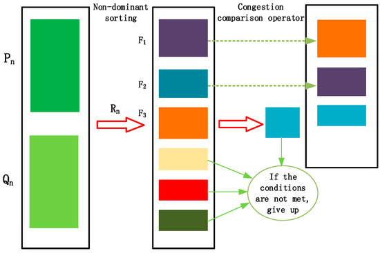
Figure 1.
Implementation steps of the elitist strategy in the NSGA-II algorithm.
Firstly, the offspring population generated in the -th generation is combined with the parent population to form a new population with a size of 2N. Then, non-dominated sorting is performed on , resulting in multiple non-dominated sets , and the crowding distance of each individual is calculated. The sorted non-dominated set represents the optimal individuals in the entire population. These individuals are given priority to be selected into the new parent population . If the size of is still less than , the next non-dominated set is considered. When the size of exceeds , individuals must be selected from using the crowding distance comparison operator to ensure that the size of equals . Finally, genetic operators (selection, crossover, and mutation) are applied to generate the new offspring population .
2.3. Multi-Objective Optimization Modeling for Gear Modification
The objective functions focus on the normal load per unit length of the helical gear surface and the vibration amplitude within the gear transmission system. The optimization variables encompass the helicity direction modification amount, the starting position for parabolic modification towards the tip, the maximum modification amount at the tip, the starting position for parabolic modification towards the root, and the maximum modification amount at the root. Constraints are established based on the traditional scheme, and the multi-objective optimization function is formulated using the linear weighted summation approach. Thus, the optimization variables are as follows:
Among them, is the matrix of optimization variables; is the helicity direction modification amount; is the tooth profile tip modification position; is the starting position of the parabolic modification towards the root; is the maximum tooth profile tip modification amount; is the maximum tooth profile root modification amount. The objective functions are as follows:
Among them, and are weighting factors, where = 0.4 and = 0.6 in this paper; is the order-of-magnitude coefficient, which is taken as 7 in this paper; is the function of normal load per unit length; is the function of gear vibration amplitude; is the objective function. The constraints are as follows:
Among them, , , , , and are the lower limits of the helicity direction modification amount, the starting position of the parabolic modification towards the tip, the starting position of the parabolic modification towards the root, the maximum modification amount towards the tip, the maximum modification amount towards the root, and the lower limit of the maximum modification amount of the parabolic modification of the tooth profile towards the root, respectively; , , , , and are the upper limits of the helicity direction modification amount, the starting position of the parabolic modification towards the tip, the starting position of the parabolic modification towards the root, the maximum modification amount towards the tip, and the maximum modification amount towards the root, respectively.
2.4. Dynamic Modeling of Helical Gears
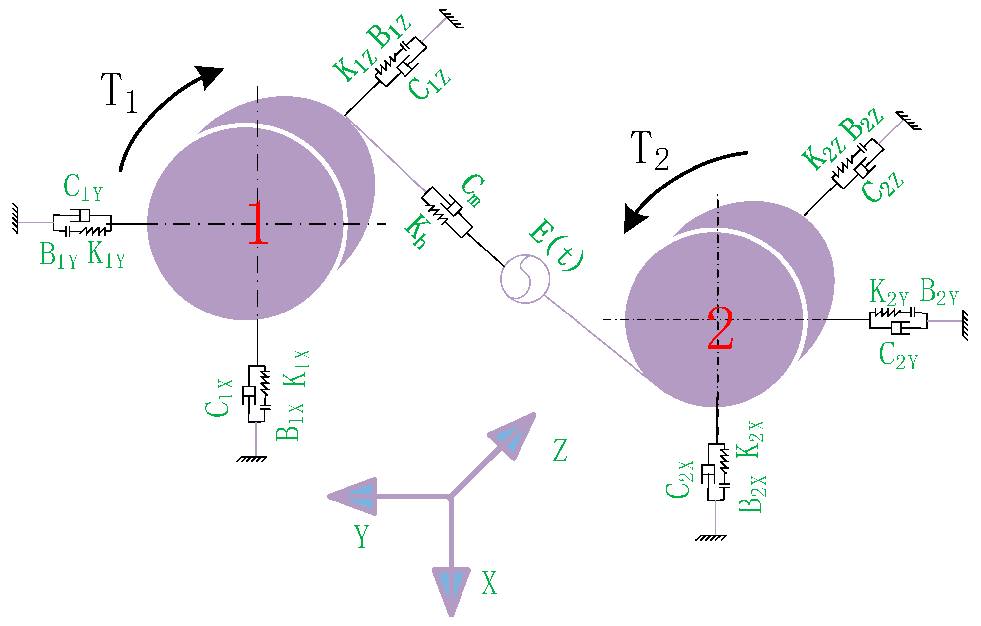
To investigate the impact of multi-objective optimization modification on the dynamic characteristics of gear transmission systems, it is necessary to conduct dynamic modeling of the helical gear transmission system. Based on the force conditions during the meshing of helical gear pairs, an eight-degree-of-freedom (DOF) bending–torsion–axial coupled dynamic model of helical gears considering backlash and bearing clearance has been established. This model includes two rotational DOFs and six translational DOFs. The rotational DOFs are and around the Z-axis, while the translational DOFs are , , , , , and along the X, Y, and Z axes, respectively. For details, see Figure 2.

Figure 2.
Dynamic model of helical gear pair.
In this nonlinear dynamic model of the helical gear system, gear 1 is the driving gear, and gear 2 is the driven gear. represents the moment of inertia of gear . , , and are the micro-displacements of gear along the , , and axes, respectively, where and represent the micro-acceleration and velocity of the gear along the axial direction, respectively. is the base circle radius of gear . The directions of and are the same as that of . and represent the equivalent support stiffness and damping, respectively. and are the meshing damping and meshing stiffness of the helical gear pair, respectively. is the static transmission error. and represent the input torque and output torque, respectively. is the rotational angular displacement (where = 1, 2; = X, Y, Z). According to Newton’s second law, the dynamic differential equations of the helical gear transmission system can be obtained as shown in Equation (6).
In the formula, is the mass of gear ; is the force on gear in the direction of (where = 1, 2; = X, Y, Z).
In the formula, is the pressure angle, and is the helix angle.
The time-varying meshing stiffness of the gear pair is [20,21]
In the formula, is the average value of the meshing stiffness; is the amplitude of the -th harmonic of the meshing stiffness; is the meshing frequency of the gear pair; is the phase angle of the -th order of the time-varying meshing stiffness.
The relative micro-displacement of the helical gear pair along the direction of the meshing point caused by vibration and error is
In the formula [22,23]
In the helical gear transmission system, the significant difference in the order of magnitude between the meshing stiffness coefficient and the transmission error coefficient can cause great difficulties in solving the equations. Therefore, it is necessary to perform non-dimensionalization of the dynamic differential equations of the helical gear transmission system. Introducing the dimensionless parameters, , , , , and the characteristic frequency , where represents the equivalent mass of the gear meshing pair, and represents the equivalent mass of gear , the non-dimensional dynamic differential equations are then given by
In the formula, ; ; ; , ; ; ; represents the support clearance function of gear in the direction.
3. Multi-Objective Optimization of Helical Gear Modification
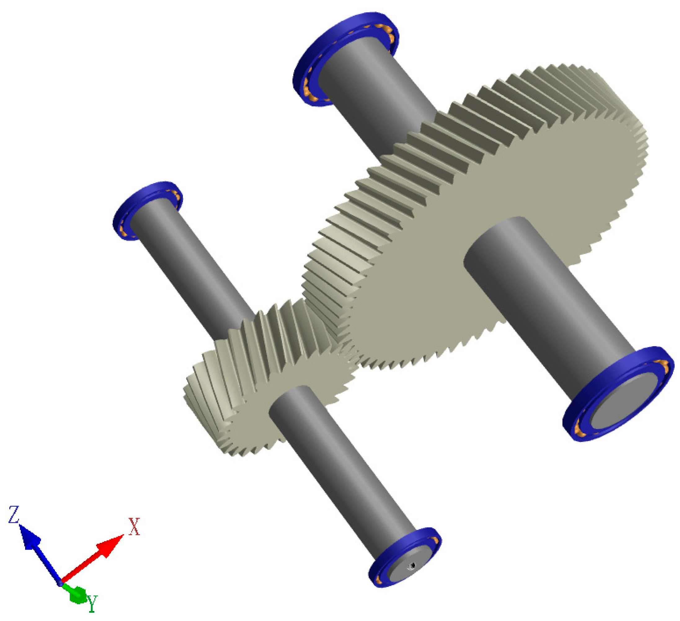
The research object of this paper is a helical gear pair transmission system, with an input power of 525 and an input speed of 1500 applied to the system. Table 2 lists the basic parameters of this helical gear pair. Figure 3 is a 3-D model of the helical gear pair transmission system.
Table 2.
Parameters of the helical gear pair.
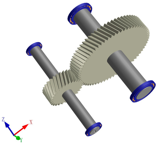
Figure 3.
Three-dimensional model of the helical gear pair transmission system.
In this study, the modification surface is selected as the right flank of the driven gear (helical gear 2). First, the traditional modification scheme parameters are determined based on the operating conditions of the helical gear transmission system.
The helicity direction modification is chosen to be crowned. The modification length for this type is half of the tooth width, and the modification amount is commonly selected as . Based on the tooth surface load distribution, it is temporarily set to 15.6 µm here. The tooth profile modification is divided into two sections. The modification curve is chosen to be a Walker modification curve with a parameter of 1.5. The starting position for parabolic modification towards the tip is temporarily set at 17.03°, and the starting position for parabolic modification towards the root is temporarily set at 10.32°. The maximum modification amount for parabolic modification towards the tip is determined using the H.Sigg formula for the driven gear. By substituting parameters such as the tangential force and tooth width , the maximum modification amount for the tooth profile modification towards the tip is calculated to be 6.012 µm. The maximum modification amount for parabolic modification towards the root is determined using the Rolls-Royce formula. By substituting parameters such as the helix angle , tangential force , tooth width , tooth width at the root , and tooth shape factor from the meshing analysis model, the maximum modification amount for the tooth profile modification towards the root is calculated to be 7.033 µm.
After completing the traditional modification scheme, the next step is to further modify the right flank of the pinion (helical gear 2) based on the above foundation using the NSGA-II algorithm. The mutation probability of the algorithm is set to 0.2, the crossover probability to 0.3, the population size to 50, and the number of generations to 30.
To avoid an excessively broad search range of the NSGA-II algorithm, which could waste unnecessary time, the search range of the NSGA-II algorithm is set by referring to the traditional modification scheme. The helicity direction modification range is set to 13–20 µm, the starting position range for parabolic modification towards the tip is set to 12–22°, the maximum modification amount range for parabolic modification towards the tip is set to 2–10 µm, the starting position range for parabolic modification towards the root is set to 5–15°, and the maximum modification amount range for parabolic modification towards the root is set to 2–12 µm. The algorithm logic flow is shown in Figure 4.
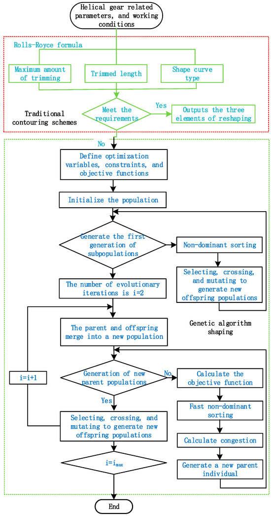
Figure 4.
The improved genetic algorithm modification process.
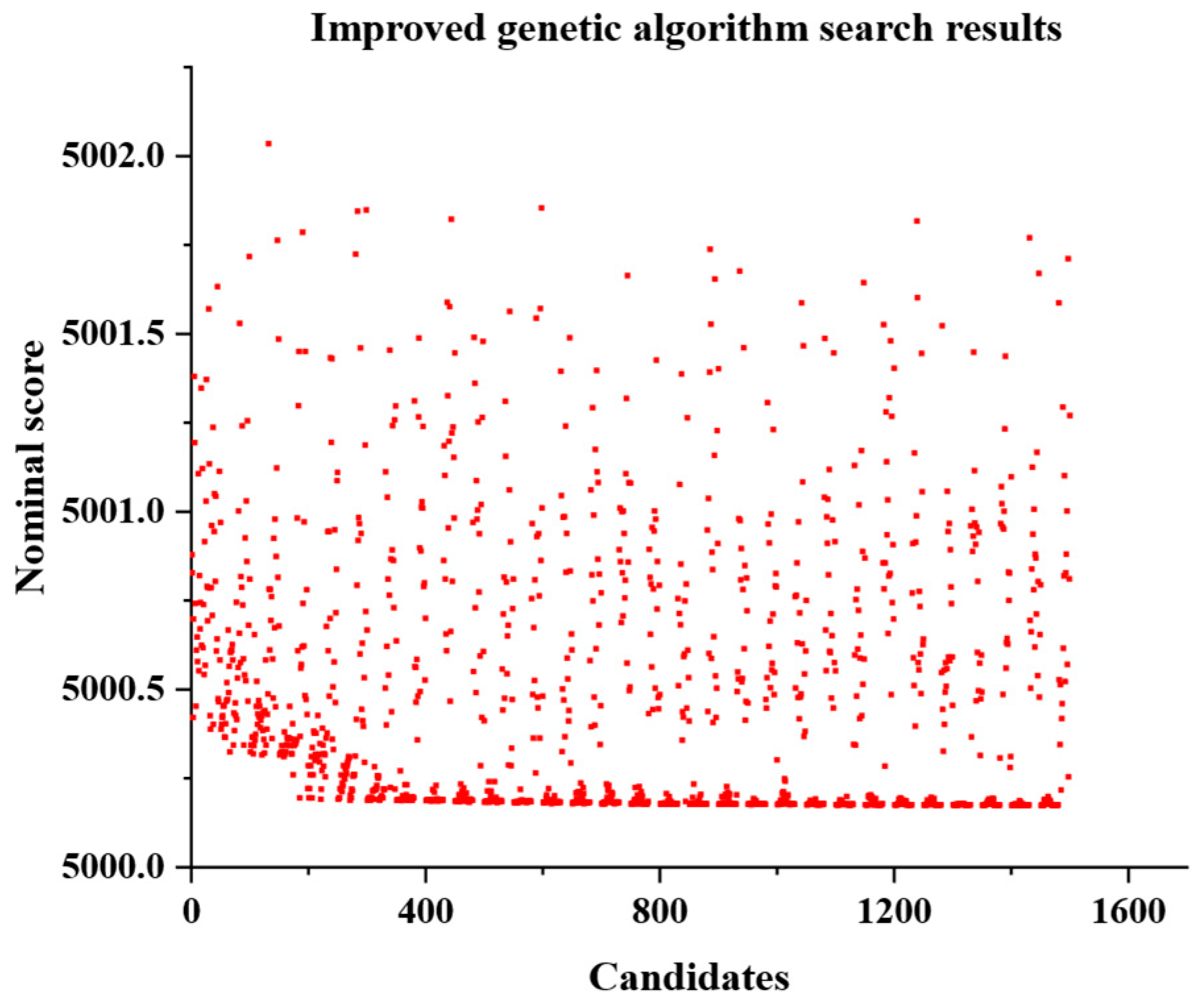
After completing all parameter settings and running the algorithm, a candidate solution–nominal score plot as shown in Figure 5 can be obtained.
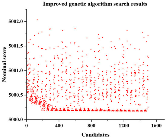
Figure 5.
Candidate solutions–nominal scores.
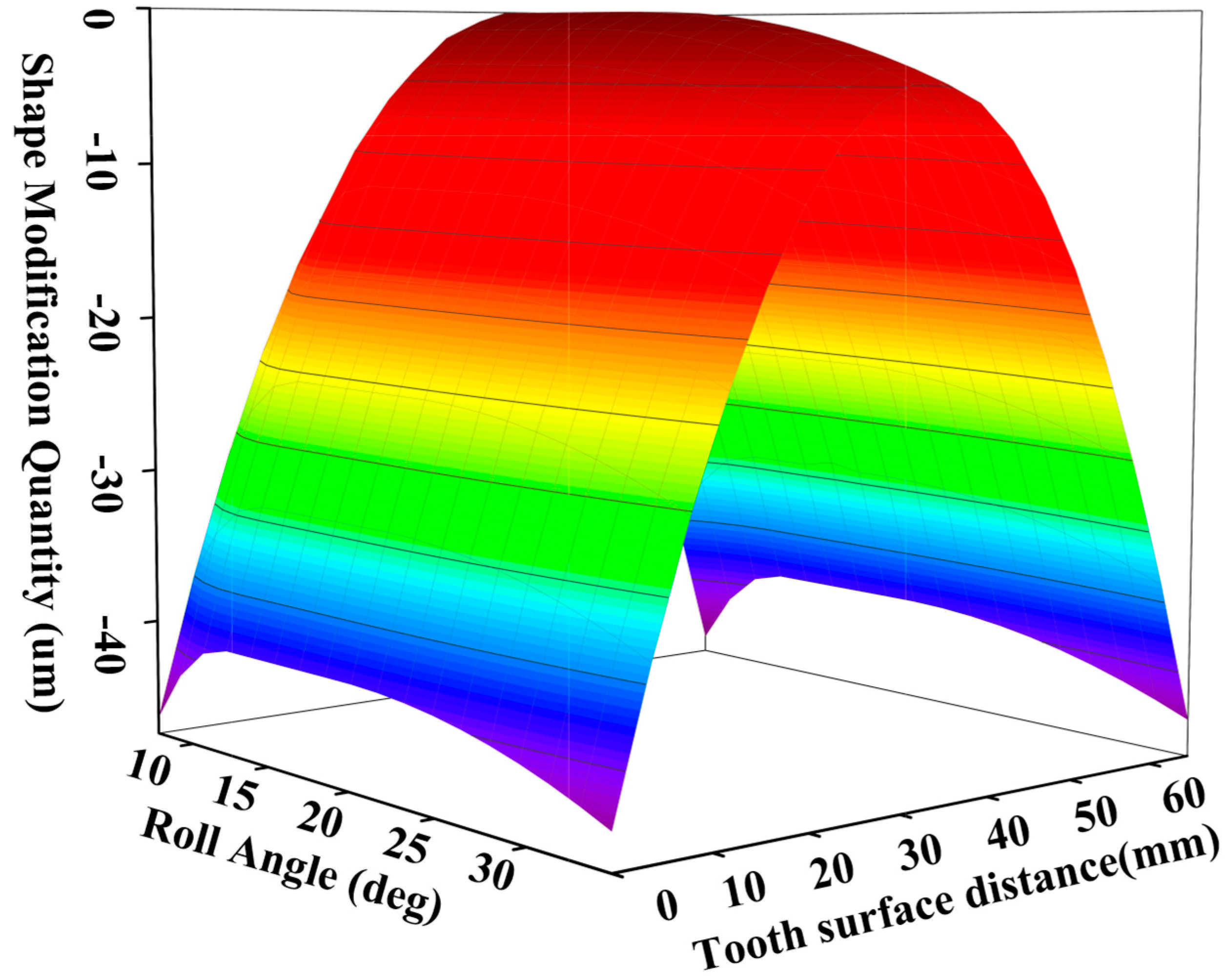
As can be seen from Figure 5, among the 1500 candidate solutions, the 1475th candidate solution has the lowest comprehensive score of 5000.17354 points, indicating that this set of modification parameters is the optimal one. Therefore, this set of solutions is applied to the modification of the right flank of the large gear, that is, the driven gear (Gear 2). Specifically, the helicity direction modification amount on the right flank of the driven gear (Gear 2) is 20 μm, the parabolic tip chamfer amount is 4.34 μm, the starting point for parabolic tip chamfer is at 19.543 degrees, the parabolic root chamfer amount is 5.62 μm, and the starting point for parabolic root chamfer is at 12.171 degrees. Figure 6 shows the three-dimensional view of the tooth surface of the driven gear (Gear 2) after modification using the improved genetic algorithm.
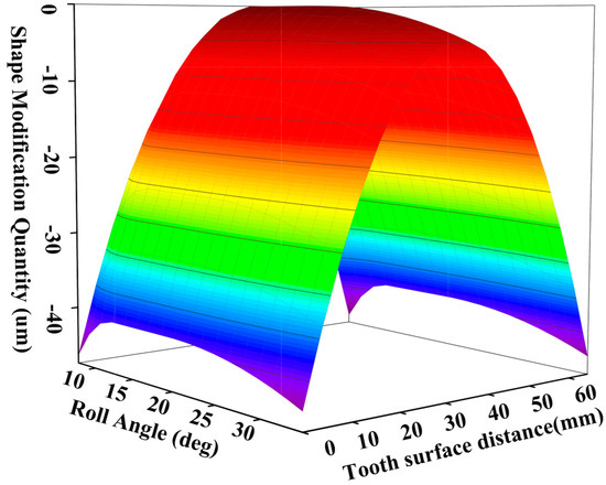
Figure 6.
Three-dimensional modification of the right flank of the driven gear.
4. Analysis of Tooth Surface Load and Vibration Before and After Modification
4.1. The Magnitude and Distribution of Normal Load per Unit Length on the Tooth Surface
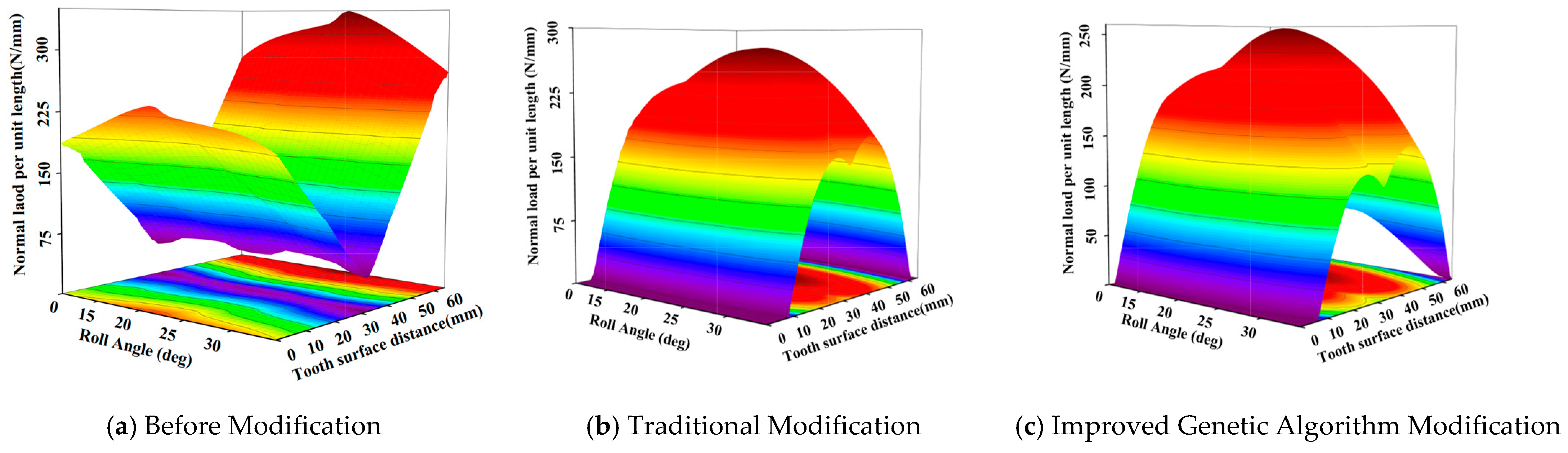
The helical gear transmission system model was subjected to both the traditional modification scheme and the improved genetic algorithm modification scheme. Finite element analysis software was utilized to evaluate the helical gear models under these three conditions: unmodified, modified using the traditional method, and modified using the improved genetic algorithm. The results, depicted in Figure 7, reveal the magnitude and distribution of the normal load per unit length for each state.
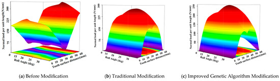
Figure 7.
The normal load per unit length on the right flank of the pinion under the three conditions.
Before modification, the maximum normal load per unit length on the right flank of the pinion (Gear 2) is 349.535 N/mm, and the minimum normal load per unit length is 39.36 N/mm, with a span of 310.170 N/mm. After traditional modification, the maximum normal load per unit length on the right flank of the pinion (Gear 2) is reduced to 277.406 N/mm, and the minimum normal load per unit length is 0 N/mm, with a span of 277.406 N/mm. After modification using the improved genetic algorithm, the maximum normal load per unit length on the right flank of the pinion (Gear 2) is further reduced to 257.469 N/mm, and the minimum normal load per unit length remains at 0 N/mm, with a span of 257.469 N/mm. Thus, traditional modification reduces the maximum normal load per unit length by 20.6%, while the improved genetic algorithm modification reduces it by 26.34%. Traditional modification reduces the span of the normal load per unit length by 10.56%, and the improved genetic algorithm modification reduces it by 16.99%. The distribution of the normal load per unit length also shifts from the edge of the tooth towards the center of the tooth with modification.
4.2. Vibration Amplitude Analysis
The vibration amplitude serves as a crucial metric for assessing gear vibration and noise levels. In this research, the gear transmission system’s parameters under three scenarios—unmodified, modified with the traditional approach, and modified with the enhanced genetic algorithm—are individually inserted into Equation (11). Subsequently, the model of the helical gear’s torsion–rotation–axial coupled transmission system is solved using the fourth-order Runge–Kutta method. The resulting time histories for these three conditions are depicted in Figure 8.
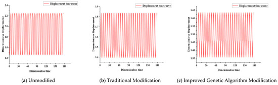
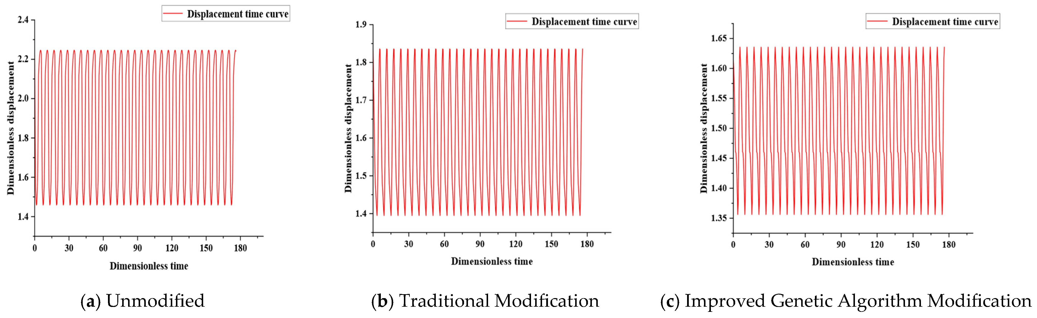
Figure 8.
Time histories of the transmission system under the three conditions.
From the time history plot in Figure 8a for the unmodified gear, it can be seen that the maximum vibration of the gear before modification is 2.2469, the minimum vibration is 1.4568, and the vibration amplitude is 0.7901. From the time history plot in Figure 8b for the gear modified using the traditional scheme, it is observed that after modifying the helical gear using the traditional scheme, the maximum vibration of the gear is 1.83581, the minimum vibration is 1.39485, and the vibration amplitude is 0.44096. From the time history plot in Figure 8c for the gear modified using the improved genetic algorithm, it is known that after modifying the pinion using the improved genetic algorithm, the maximum vibration of the gear is 1.6358, the minimum vibration is 1.35911, and the vibration amplitude is 0.27669. Therefore, traditional modification reduces the gear vibration amplitude by 18.3%, while the improved genetic algorithm modification reduces it by 27.2%. Traditional modification reduces the minimum vibration of the gear by 4.25%, and the improved genetic algorithm modification reduces it by 6.71%. Traditional modification reduces the variation in gear vibration by 44.19%, and the improved genetic algorithm modification reduces it by 64.98%.
5. Conclusions
- (1)
- Compared to traditional modification methods, the improved genetic algorithm modification based on traditional methods shows better performance in reducing the normal load per unit length of the tooth surface. The maximum normal load per unit length is reduced from 20.6% to 26.34%. This provides theoretical and data support for further improving the load transmission capacity and service life of gear transmission systems.
- (2)
- Compared to traditional modification methods, the genetic algorithm modification based on traditional methods shows better performance in reducing the vibration amplitude of gear transmission systems. The vibration amplitude reduction is increased from 18.3% to 27.2%. This offers theoretical and data support for further development in vibration reduction and noise control in gear transmission systems.
- (3)
- The improved genetic algorithm modification used in this study avoids the drawbacks of a broad search range and the need for multiple modifications to find the optimal solution. This significantly saves labor and material resources, providing a method for reducing the production cost of high-precision gears.
Author Contributions
Conceptualization, S.Z. and D.Z.; software and data curation, S.Z.; writing—original draft preparation, D.Z. All authors have read and agreed to the published version of the manuscript.
Funding
This research was funded by the National Natural Science Foundation of China (Grant number No. 52275295); the Horizontal Project of Zhengzhou University of Light Industry (Project number No. JDG20210045); and the Henan Provincial Science and Technology Research Project (Grant number No. 242102230034).
Data Availability Statement
The original contributions described in this study are detailed within the article. For further information, please contact the corresponding author.
Acknowledgments
This work was supported by the Zhengzhou University of Light Industry and the Henan Provincial Department of Science and Technology.
Conflicts of Interest
The authors report no conflicts of interest.
References
- Qiu, P.Y.; Wang, L.X.; Peng, Y.J.; Qiao, H.; Lin, Y.H. Influence of different combinations of high-order topological modification on contact pattern and load distribution of helical gear. Trans. Can. Soc. Mech. Eng. 2024, 48, 146–163. [Google Scholar] [CrossRef]
- Yang, J.; Lin, T.J. Calculation method and parameter optimization for friction power loss of the modified double-helical gear transmission. Meccanica 2023, 58, 1–23. [Google Scholar] [CrossRef]
- Jia, C.; Zhang, G. Investigation on the dynamic characteristics of non-orthogonal helical face gears with higher-order tooth surface modification. Mathematics 2024, 12, 366. [Google Scholar] [CrossRef]
- Liu, Y.; Gong, J.Y. Study on tehl flash temperature of helical gear pair considering profile modification. Ind. Lubr. Tribol. 2023, 75, 17–26. [Google Scholar] [CrossRef]
- Yang, Y.M.; Wang, Z.H.; Kubo, A. Research on high-precision measuring technology of gear grinder based on the consideration of machine tool thermal error and probe pre-travel error. Int. J. Adv. Manuf. Technol. 2024, 135, 5187–5211. [Google Scholar] [CrossRef]
- Abderazek, H.; Laouissi, A.; Nouioua, M.; Atanasovska, I. Recent swarm intelligence techniques for optimal spur gear design. Proc. Inst. Mech. Eng. Part C-J. Mech. Eng. Sci. 2025. [Google Scholar] [CrossRef]
- Baglioni, S.; Cianetti, F.; Landi, L. Influence of the addendum modification on spur gear efficiency. Mech. Mach. Theory 2012, 49, 216–233. [Google Scholar] [CrossRef]
- Chen, S.Y.; Tang, J.Y.; Chen, W.T.; Hu, Z.H.; Cao, M.P. Nonlinear dynamic characteristic of a face gear drive with effect of modification. Meccanica 2014, 49, 1023–1037. [Google Scholar] [CrossRef]
- Motahar, H.; Samani, F.S.; Molaie, M. Nonlinear vibration of the bevel gear with teeth profile modification. Nonlinear Dyn. 2016, 83, 1875–1884. [Google Scholar] [CrossRef]
- Ni, G.X.; Zhu, C.H.; Song, C.S.; Du, X.S.; Zhou, Y. Tooth contact analysis of crossed beveloid gear transmission with parabolic modification. Mech. Mach. Theory 2017, 113, 40–52. [Google Scholar] [CrossRef]
- Jia, H.J.; Qin, D.T.; Liu, C.Z. Novel tooth modification methodology for multistage spur gears considering dynamic deformation of housing. Proc. Inst. Mech. Eng. Part C-J. Mech. Eng. Sci. 2019, 233, 7257–7269. [Google Scholar] [CrossRef]
- Zou, H.; Wang, S.; Li, F.; Liu, L.; Li, L.; Li, Z. Improved algorithm of tooth surface topological modification and nonlinear dynamic analysis of herringbone gears. Mech. Mach. Theory 2023, 180, 105151. [Google Scholar] [CrossRef]
- Zhou, D.; Guo, Y.L.; Yang, J.; Zhang, Y.M. Study on the Parameter Influences of Gear Tooth Profile Modification and Transmission Error Analysis. Machines 2024, 12, 316. [Google Scholar] [CrossRef]
- Han, G.Z.; Huang, K.; Xiong, Y.S.; Zhu, G.D.; Peng, J.Y. An analysis of time-varying meshing stiffness of high contact ratio gears considering a high-order modification curve. Trans. Famena 2024, 48, 145–162. [Google Scholar] [CrossRef]
- Autiero, M.; Paoli, G.; Cirelli, M.; Valentini, P.P. The effect of different profile modifications on the static and dynamic transmission error of spur gears. Mech. Mach. Theory 2024, 201, 105752. [Google Scholar] [CrossRef]
- Li, Z.T.; Chen, Y.H.; Wang, X.H.; Lou, W.J.; Chen, B.K. Local Conjugate Meshing Performance Analysis of an Enveloping Hourglass Worm Drive Based on Medium Gear. J. Mech. Des. 2025, 147, 033501. [Google Scholar] [CrossRef]
- Hao, D.; Zhang, Z.Y.; Liu, S.-S.; Hou, X.-Y.; Jin, G.-H.; Wang, C.-J. Nonlinear bifurcation characterization of the herringbone gear transmission system based on topological modification time-varying meshing stiffness. J. Strain Anal. Eng. Des. 2025. [Google Scholar] [CrossRef]
- Wang, C. A calculation method of thermal deformation for double helical gear. Mech. Ind. 2019, 20, 612. [Google Scholar] [CrossRef]
- Chen, L.; Yu, Y.; Shang, Y.P.; Wang, Z.H.; Zhang, J. Application of isogeometric analysis method in three-dimensional gear contact analysis. CMES-Comput. Model. Eng. Sci. 2024, 139, 817–846. [Google Scholar] [CrossRef]
- Wang, R.Y.; Wang, J.H.; Yang, J.W.; He, Y.P.; Yao, D.C. An investigation into the effects of profile shifts on helical gear mesh stiffness. Mech. Based Des. Struct. Mach. 2025, 53, 499–518. [Google Scholar] [CrossRef]
- Wang, L.; Du, Y.P.; Bai, H.J.; Wang, Z.H.; Dou, S.H. Research on nonlinear characteristics of multi-clearance gear system based on fractal theory. Int. J. Non-Linear Mech. 2025, 170, 104995. [Google Scholar] [CrossRef]
- Ghosh, S.S.; Chakraborty, G. On optimal tooth profile modification for reduction of vibration and noise in spur gear pairs. Mech. Mach. Theory 2016, 105, 145–163. [Google Scholar] [CrossRef]
- Sanchez, M.B.; Pleguezuelos, M.; Pedrero, J.I. Influence of profile modification on the transmission error of spur gears under surface wear. Mech. Mach. Theory 2024, 191, 105473. [Google Scholar] [CrossRef]


Disclaimer/Publisher’s Note: The statements, opinions and data contained in all publications are solely those of the individual author(s) and contributor(s) and not of MDPI and/or the editor(s). MDPI and/or the editor(s) disclaim responsibility for any injury to people or property resulting from any ideas, methods, instructions or products referred to in the content. |
© 2025 by the authors. Licensee MDPI, Basel, Switzerland. This article is an open access article distributed under the terms and conditions of the Creative Commons Attribution (CC BY) license (https://creativecommons.org/licenses/by/4.0/).