Article

A Novel Ground-to-Elevated Mobile Manipulator Base System for High-Altitude Operations

1
Huzhou Institute, Zhejiang University, Huzhou 313000, China
2
College of Control Science and Engineering, Zhejiang University, Hangzhou 310027, China
3
Jiuquan Satellite Launch Center, Jiuquan 735700, China
*
Author to whom correspondence should be addressed.
Machines 2025, 13(4), 288; https://doi.org/10.3390/machines13040288
Submission received: 5 March 2025 / Revised: 27 March 2025 / Accepted: 28 March 2025 / Published: 31 March 2025
(This article belongs to the Section Machine Design and Theory)

Abstract

Mobile manipulators have the potential to replace manual labor in various scenarios. However, current mobile base designs have limitations when it comes to accommodating complex movements that involve both high-altitude tasks and ground-based composite tasks. This paper presents a new design for the mobile manipulator base, which utilizes a time-sharing drive with gears and differential wheels. Additionally, a new foldable mechanical gear-track system has been developed, enabling the robot to effectively operate on both the ground and the mechanical gear-tracks. To address the challenges of power distribution and localization caused by the mechanical characteristics of the designed track, this study proposes a precise pose estimation method for the robot on the mechanical gear-track, along with a compliance control method for the gears. Furthermore, a segmented multi-sensor fusion navigation approach is introduced to meet the high-precision motion control requirements at the entrance of the designed track. Experimental results demonstrate the effectiveness of the proposed new mobile manipulator base, as well as its corresponding control methods.

1. Introduction

Elevated work environments often pose significant safety risks to human workers. A mobile manipulator, thanks to its flexible mobile base and high degree of freedom operator hand, can perform a wider range of operation tasks and replace manual work in many scenarios [1]. In the work-at-height operation situation, there are problems such as heavy manual workload, high risk factor, and complex and variable operation scenes. For instance, the environment discussed in this article is illustrated in Figure 1. In fields such as cargo transportation and storage management, height cleaning operations, and power inspection and maintenance, there is a need for mobile robots to perform operations both on the ground and at high altitudes. This would allow them to effectively handle a wide range of work-at-height operation scenarios. Although there have been several advancements in the design of mobile bases to accommodate various complex environments, there are limitations when it comes to tasks that involve both ground and height operations using the current bases.
Currently, the majority of research on the robot mobile base of mobile manipulators focuses primarily on ground motion [2,3,4], with a major characteristic being the use of wheeled mobile bases. Thakar et al. developed a base, motion planning, and coordination of the manipulator to complete specific tasks, such as indoor disinfection spraying [5], in a flat indoor environment. Piyapunsutti et al. used a base in a restaurant environment to provide food and drinks as an automated navigation service robot for customers [6], among other examples. However, as tasks and environments become more complex, conventional bases struggle to meet the requirements. Some researchers have studied the mobility and increased motion capabilities of mobile bases in more complex environments. For instance, K. Tadakuma et al. proposed a cylindrical track platform based on a caterpillar-like mechanism to achieve lateral motion [7,8]. Ernits and Hoppe [9], as well as Fiede´n and Bałchanowski [10], proposed track-type mobile platforms composed of Mecanum wheels. These solutions, to some extent, address how to extend the adaptability of mobile robots to various special ground environments, but these mobile platforms are unable to meet the requirements of work-at-height operations. In order to enable robots to perform tasks at high places, some researchers have developed a track-type robot mobile base, which has shown unique application value in scenarios such as height inspections of substations [11] and suspended powder feeding operations [12]. This type of robot mobile base successfully overcomes the limitations of traditional operating ranges, effectively extending the task execution area of the operating robot from the ground to high places. However, most of these track-type robot mobile bases fix the robot body on a pre-designed horizontal track, resulting in limited operating range and occupying a large amount of space for track deployment and installation, as well as posing significant challenges for maintenance. Xu et al. also designed a climbing robot with four-wheel magnetic adhesion for welding work on large steel surfaces [13], which has good mobility, but its operating environment is only suitable for large, flat, magnetically attachable surfaces. Liu et al. proposed a new climbing robot with spiked tracks and a double-track mechanism [14], which can climb on rough vertical surfaces and has good flexibility. However, its special structural design results in weak load capacity, making it difficult to replace humans in general load-bearing tasks. Once a large load is added, its climbing ability will be limited.
Existing academic research highlights significant challenges in achieving composite motion for ground-to-high transitions and simultaneously performing dexterous operations with mobile manipulator robot bases. In response to these challenges, this paper proposes an innovative configuration design for a mobile robot base. The core innovation of this design lies in enabling the robot to operate freely and dexterously in both ground and elevated environments. This mobile base utilizes a gear and differential wheel time-sharing drive mechanism, combined with a 6-DOF (degree-of-freedom) robotic arm, to meet the demanding requirements for flexibility and precision in complex tasks. However, this new base design introduces several challenges: at the mechanical structure level, it is essential to develop a compatible track system to facilitate climbing; at the control method level, the mobile base must ensure the robot can perform dexterous operations across a wide range of ground areas and at elevated positions, which presents significant challenges to its positioning and control methods; additionally, achieving stable and smooth climbing operations on the designed track is a major challenge. Following the presentation of this mobile robot base configuration, this paper briefly addresses the related issues arising from the reliable operation of the entire robot system based on this base and provides corresponding solutions. The specific challenges are as follows:
(1)
For the mobile base designed in this study, it is essential to thoroughly consider the feasibility of manufacturing and transportation, as well as the flexibility of adjustment and adaptation in practical applications. This ensures that its mobility and adaptability are superior to those of fixed tracks when addressing diverse work sites and task requirements.
(2)
Accurate pose estimation of robots at high altitudes serves as the foundation for flexible operations in elevated environments. However, existing height estimation methods exhibit certain limitations. For instance, the accuracy of height measurement using LiDAR is constrained [15]. Additionally, in the actual scene described in this paper, the measured plane is uneven and subject to strong vibrations caused by movement, which makes the measurement data unreliable. When using RTK (real-time kinematic) devices for height estimation, there is a problem of insufficient accuracy [16]. The utilization of infrared ranging sensors also presents disadvantages, such as interference from strong environmental light and a limited measurement range [17].
(3)
In the climbing drive section of our base configuration, we implement a rigidly connected independent drive motor architecture. However, when encountering curved tracks with substantial curvature variations, the robot’s posture remains in a continuous dynamic state. Furthermore, the designed foldable track includes sections with missing racks, presenting a significant challenge for the smooth and seamless passage of the compliant drive gear through the curved and suspended segments of the track.
(4)
These compound mobile operation robots are primarily designed for outdoor environments [18,19]. The conventional localization method used is RTK for absolute pose estimation [20], but the accuracy of RTK devices significantly decreases when encountering strong electromagnetic interference [21]. Additionally, the mechanical track in this paper has a small allowable pose error when entering the track in order to closely match the robot body. It is difficult to meet the positioning accuracy requirements solely relying on RTK [22,23,24]. Simultaneously, for the stability of outdoor work, adaptability to harsh environments should also be considered, such as working stability under strong electromagnetic interference and adverse weather conditions.
The main contributions of this article are delineated as follows:
  • We present a new design for mobile manipulators, along with an innovative design for mechanical gear-tracks.
  • We introduce a robot navigation algorithm that is based on the fusion of multi-sensor information and localization techniques. This algorithm significantly enhances the adaptability and accuracy of localization systems within complex outdoor environments.
  • We outline a methodology for robot localization and for ensuring smooth operation on the track. This methodology addresses the challenges associated with pose estimation in a compound robot mobile base for work-at-height operations and effectively enhances the stability and smoothness of robot movement on both curved and suspended tracks.
  • A series of empirical tests were conducted in real-world environments to validate the proposed robot mobile base system and methodology.
The remainder of this article is organized as follows. Section 2 introduces the design of the mobile manipulator system and its corresponding gear-climbing track system. Section 3 describes the base control method of the base, which encompasses ground multi-sensor fusion navigation control, track localization, and compliance driving methods. Section 4 presents experiments conducted with the system designed in this article. Section 5 concludes the discussion.

2. Design

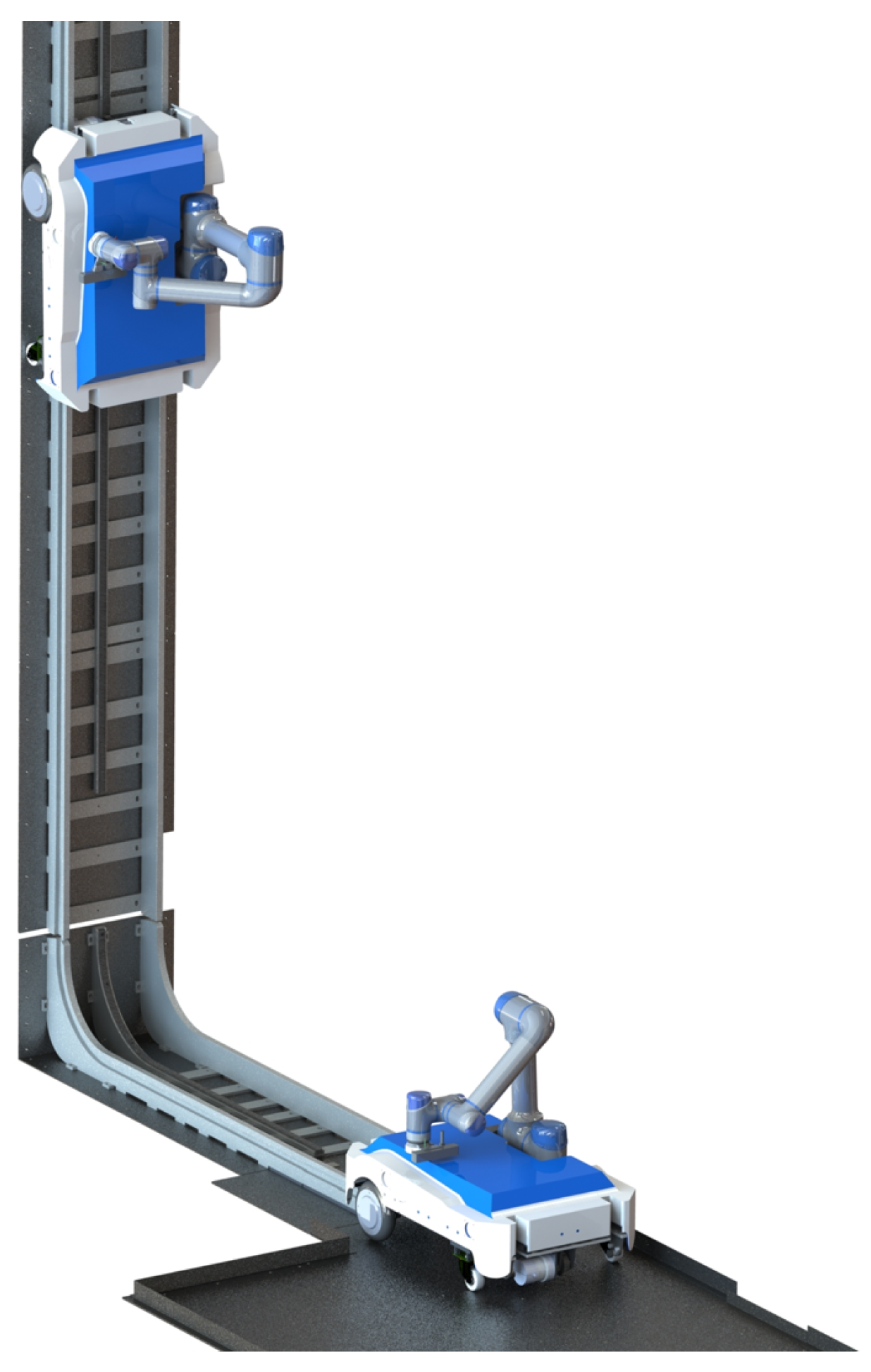
2.1. Robot General Design

The mobile manipulator system designed in this study primarily consists of a robot body and a climbing track. The robot body includes a dual-drive mobile base, a manipulator arm, and its control system hardware. The mobile manipulator system is shown in Figure 2.
The total mass of the designed robotic structure is approximately 50.5 kg, with an external envelope dimension of 610 930 750 mm in the retracted state of the robotic arm. Taking into account the mass of the robotic structure and the potential mass of the operational equipment it may carry, the drive system must be capable of supporting a maximum load of 58 kg, and the robotic arm can accommodate a maximum load of 7 kg. This robot is primarily utilized in high-altitude operation scenarios, where the working height is determined by the length of the mechanical track. The nominal working height is set at 15 m, and it must meet the requirement of rapid climbing, meaning the time required to ascend to the nominal height should not exceed 2 min. From the perspective of practical engineering applications, battery endurance is crucial. It should ensure that the robot can operate continuously for at least 2 h and remain on standby for over 8 h, thereby guaranteeing the robot’s availability and operational continuity in real-world working conditions.

2.2. Gear-Track and Gear-Climbing Mechanism Design

In the design of the mobile base in this paper, the mechanical gear-track and gear-driven climbing design are key elements for achieving its functionality. Firstly, the structural characteristics and design principles of the mechanical gear-track are introduced. Secondly, the focus is on the dual gear-driven design on the base, as well as the guiding and mechanical limit mechanisms designed on both sides of the drive wheels. The overall design diagram of the track and mobile base is shown in Figure 3.

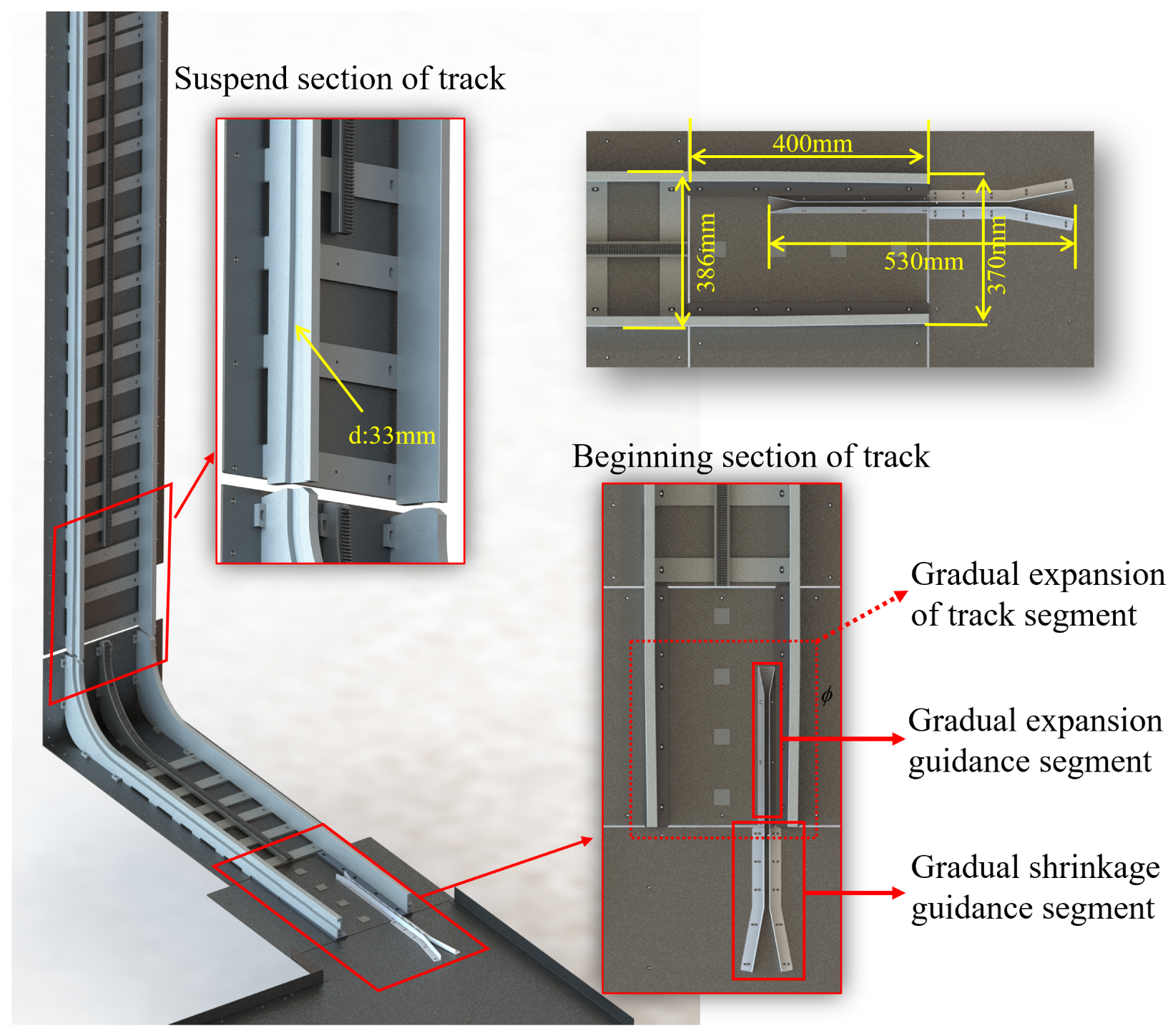
2.2.1. Gear-Track Mechanism Design

For the mobile base designed in this study, with full consideration of manufacturing and transportation feasibility, as well as the flexibility for adjustment and transplantation in practical applications, a foldable mechanical gear-track has been developed. Furthermore, a suspended track interruption structure is implemented at the beginning of the vertical track, which increases the permissible error after the track is folded and unfolded, thereby reducing the precision requirements for the track control mechanism. The folding mechanism of the track is described in Figure 4.
The mechanical track is designed to ensure coordination with the mobile base, and its design primarily comprises the vertical track, 90° curved track, horizontal track, and the front flat section. The horizontal section is set to 1.5 m, and the vertical section is set to 15 m. The schematic diagram of the track structure is illustrated in Figure 5.
The overall structure of the track primarily comprises guiding plates on both sides and a metal rack. The metal rack is installed between the guiding plates and can engage with the self-locking gear on the base drive mechanism to generate driving power. The width of the guide plate is 386 mm, and the width of the guide groove is 33 mm, which is slightly larger than the 26 mm diameter of the base’s rubber wheel. The grooves on the guiding plates facilitate the uniformity of the relative position between the base movement and the track.
The arc track is responsible for directing the robot from a horizontal surface to a vertical track. The track at the entrance consists of a combination of a gradually narrowing guiding section and a gradually widening guiding section. When the robotic base reaches the beginning of the track, it initially enters the track through these two guiding sections via the guiding rods located at its bottom. The distance between two guide rods is 510 mm, whereas the stable guide section within the gradually narrowing guiding section measures 530 mm. Subsequently, it ensures that the rubber wheels of the robotic front guiding mechanism enter the gradually widening track section, as the track width increases from an initial measurement of 370 mm to 386 mm, thereby completing a full entry onto the track.
In this study, after the curved section of the track, the rack is not directly laid on the upper vertical track—instead, a certain length of suspended track is innovatively reserved, as shown in Figure 6. One advantage of this design is that it ensures the normal folding of the track and avoids interference with the lower track. The second advantage, which is more critical, is that in the actual operation of the folding mechanism, it is impossible to ensure that it unfolds from the folded state to a completely consistent vertical state with precision and accuracy. If the rack is continuously laid, these angular errors will seriously affect the climbing of the robot. This is because in order to ensure stable and reliable climbing, the robot base needs to ensure that the gear drive is fixed relative to the rack pose and is highly sensitive to deviations. For example, if the rack is too far away from the gear, the driving gear will lose driving force due to the inability to make contact. A more severe situation is that if the rack is too close to the gear, the locking force generated by the fastening mechanism on both sides of the track and the meshing force between the middle track and the gear will create a strong opposing force. This intense mutual resistance is likely to cause damage to the mobile base. Based on this, this paper designs a foldable track joint interface and removes some of the rack, while also designing the grooves on both sides of the starting point as a trumpet-shaped guide. These two innovative designs greatly increase the allowable angular error during the unfolding of the track.

2.2.2. Gear-Climbing Mechanism Design

As illustrated in the overall design diagram of the track and mobile base in Figure 5, the robot’s mobile base must first autonomously navigate from the ground into the designated mechanical track. Following this, it will transition from a horizontal to a vertical climbing state on the mechanical track until the task is completed. Consequently, the mobile base must satisfy the following requirements:
  • It must possess the capability to autonomously enter the mechanical track from an open ground.
  • It must incorporate a mechanical limiting mechanism to ensure stable movement on the track.
  • The entire climbing process must maintain continuous power.
To address these requirements, the specific design is as follows:
  • The base moves smoothly along the track, primarily utilizing the track guidance mechanism and the track drive mechanism. Upon reaching the track’s starting place, the base employs the guide rod located at its base to initiate entry into the track through the progressively narrowing guide section. Following this, the rubber tires of the front guidance mechanism engage with the gradually widening track section.
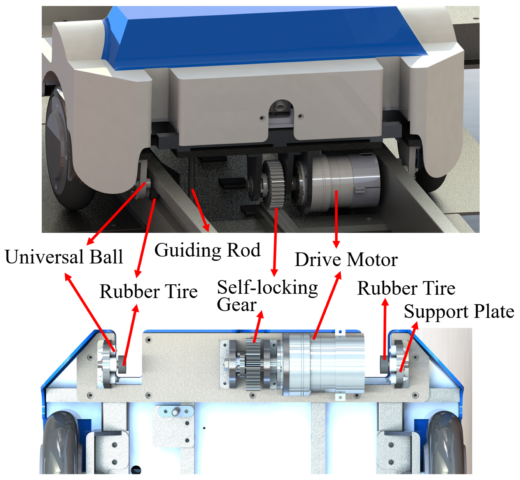
  • When the base fully enters the track, the track guiding mechanisms installed on both sides of the front and rear drive motors constrain the base to the guide rail. Each set of track guiding mechanisms comprises a rubber tire, a universal ball, and a support plate, ensuring that the base moves only in a direction parallel to the guide rail. Figure 7 below illustrates the constraint method.
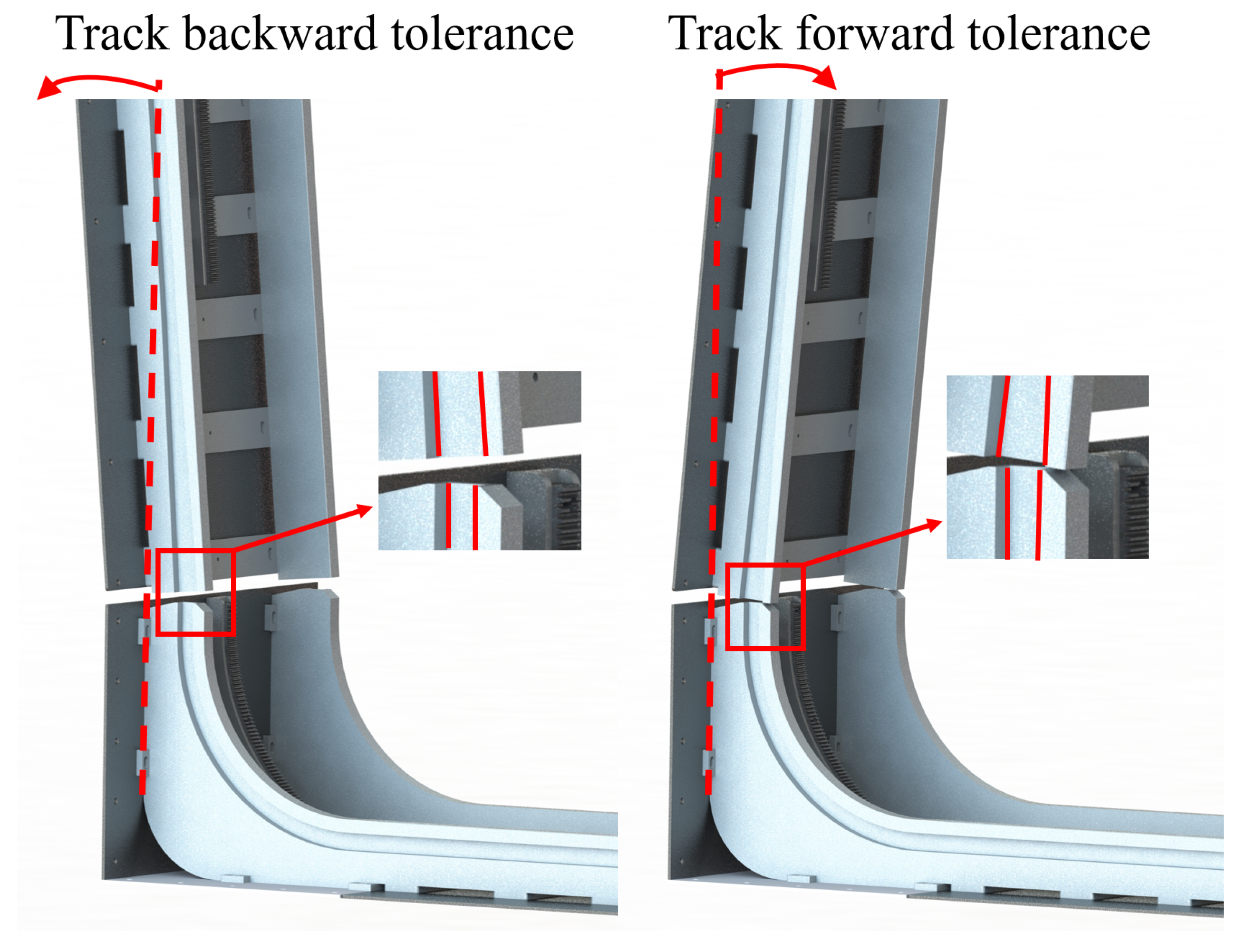
  • As illustrated in Figure 5, a gap exists in the rack of the mechanical gear-track, resulting in a power loss issue for the base when the gear is suspended at this point. To ensure continuous and stable climbing power for the base, independent and complete drive gears have been installed at both the front and rear of the base. When one gear is suspended and loses power transmission due to the interruption of the rack, the other gear can continue to provide power. Taking the drive motor mechanism on one side as an example, it primarily consists of a drive motor, support components, bearings, a shaft, and a self-locking gear, and the composition of this mechanism is depicted in Figure 8.
Among these components, the self-locking drive gear, serving as a critical element, features a module of 2.0, 40 teeth, a shaft hole diameter of 17 mm, and is capable of transmitting a torque exceeding 78 N·m.

3. Localization and Control Methods

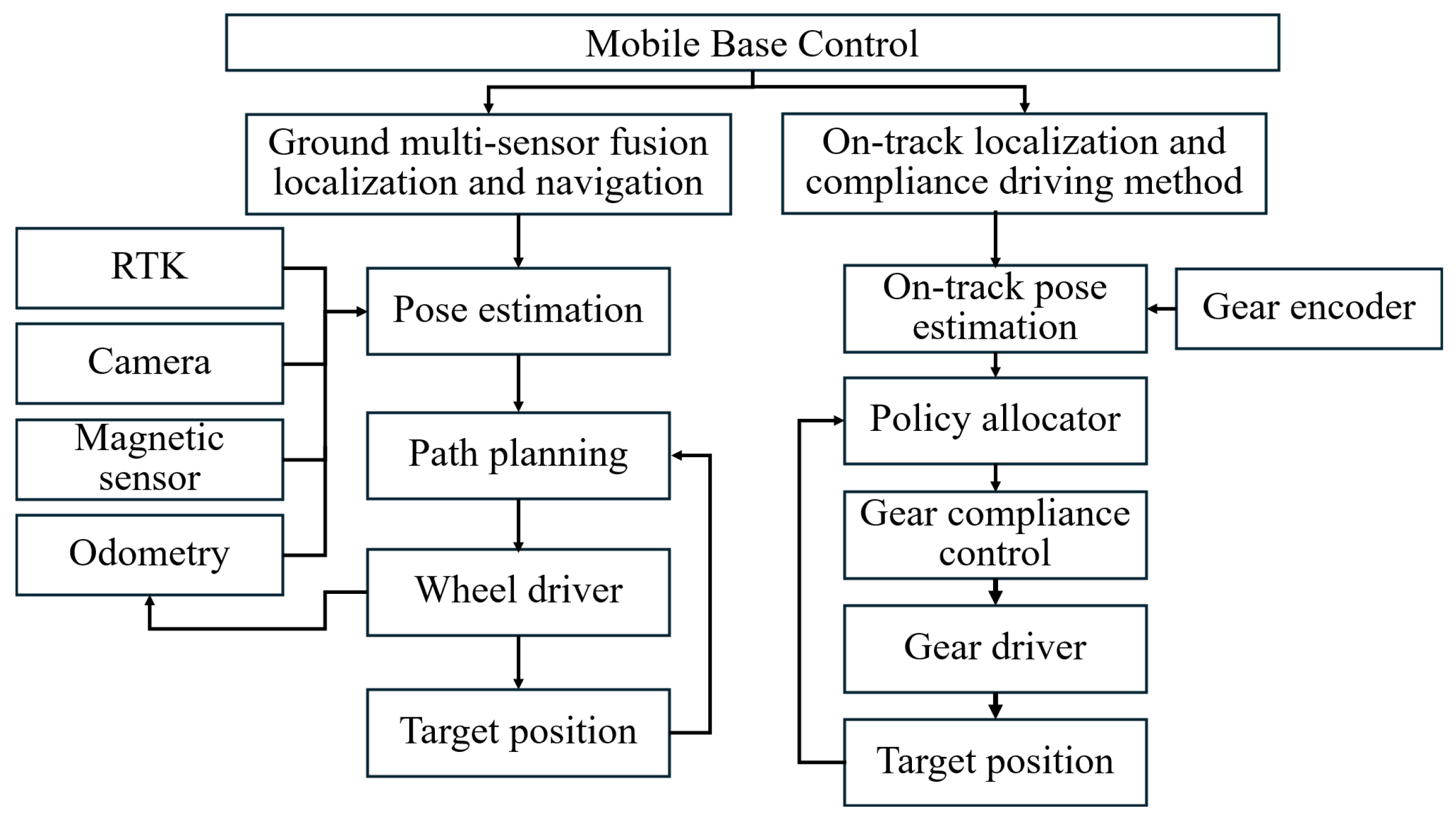
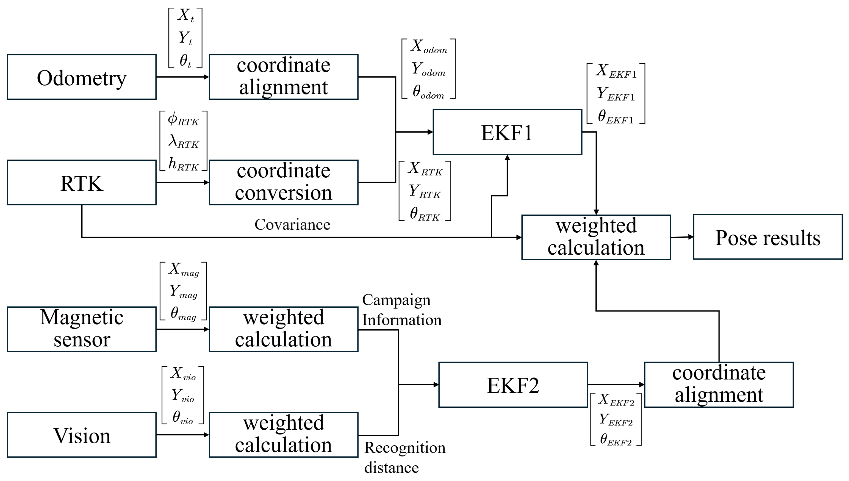
3.1. Localization and Control Framework

The overall localization and control framework of the robot mobile base consists of two main parts: navigation control method based on multi-sensor fusion localization and on-track localization and compliance driving method. In terms of navigation control, one approach is to use RTK and wheel odometry for pose estimation and path tracking on open ground. Another approach is to fuse RTK, wheel odometry, camera vision, and magnetic sensors in near-track areas to achieve more accurate pose estimation for precise on-track motion. In terms of on-track localization and smooth driving, the high-precision encoders of the gear motors are used, combined with the determined mechanical gear-track design parameters, to jointly calculate real-time pose. Based on this, real-time adjustment strategies are applied to allocate the driving motors, ensuring that the torque of the follow-up wheels follows the changes of the main driving wheel, thus achieving smooth control of the gear motors. The control block diagram is shown in Figure 9 below.

3.2. Ground Multi-Sensor Fusion Localization and Navigation Methods

Considering the susceptibility of RTK to electromagnetic interference and the difficulty in meeting the localization requirements in proximity areas when operating outdoors, we propose a segmented navigation and localization algorithm based on multi-sensor information fusion. Specifically, in open and spacious ground environments, it is sufficient for the system to achieve convergence in a limited time for localization. We use a fusion approach that combines RTK with wheel odometry for navigation. As shown in Figure 10, when the robot is about to enter the mechanical gear-track phase, we collect localization data from vision, magnetic, RTK, and wheel odometry. We consider the accuracy of individual sensor-based pose estimation and the validity of the data, and use an Extended Kalman Filter (EKF) to perform weighted fusion, allowing for high-precision pose estimation even when a single sensor fails to provide accurate localization.
The RTK localization system used in this study consists of a mobile station and a base station. The base station is installed in a fixed pose, while the mobile station is installed on the robot base. Real-time communication between the mobile station and the base station is used to calculate the pose of the mobile station in the Earth coordinate system. The wheel odometry uses motor encoder readings and motion models to estimate the robot’s displacement. The visual localization method identifies pre-set cooperative markers on the ground to compute the current pose of the robot. However, due to the complex and changing outdoor environment, monocular cameras often encounter problems such as marker contamination or shadows caused by sunlight, making it difficult to recognize the cooperative markers. In such cases, the magnetic sensor can effectively compensate for the localization gaps caused by the failure to recognize cooperative markers by detecting specially attached magnetic strips. However, the detection range of the magnetic sensor itself is relatively limited. The significant advantage of the wide range of localization offered by visual and RTK localization can complement the advantages of the magnetic sensor, thereby meeting the precise localization and stable navigation requirements of robots in complex outdoor environments.

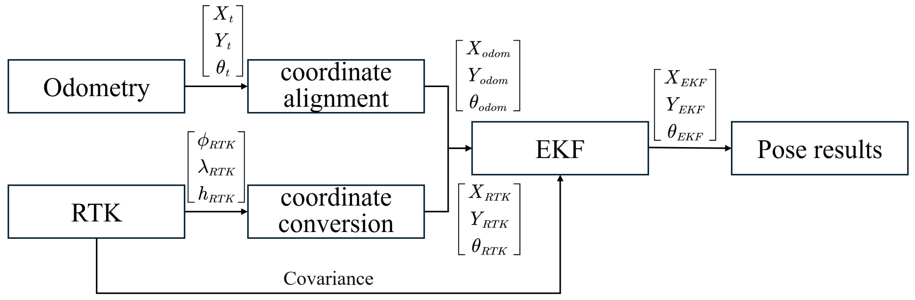
3.2.1. Methods for Open Ground
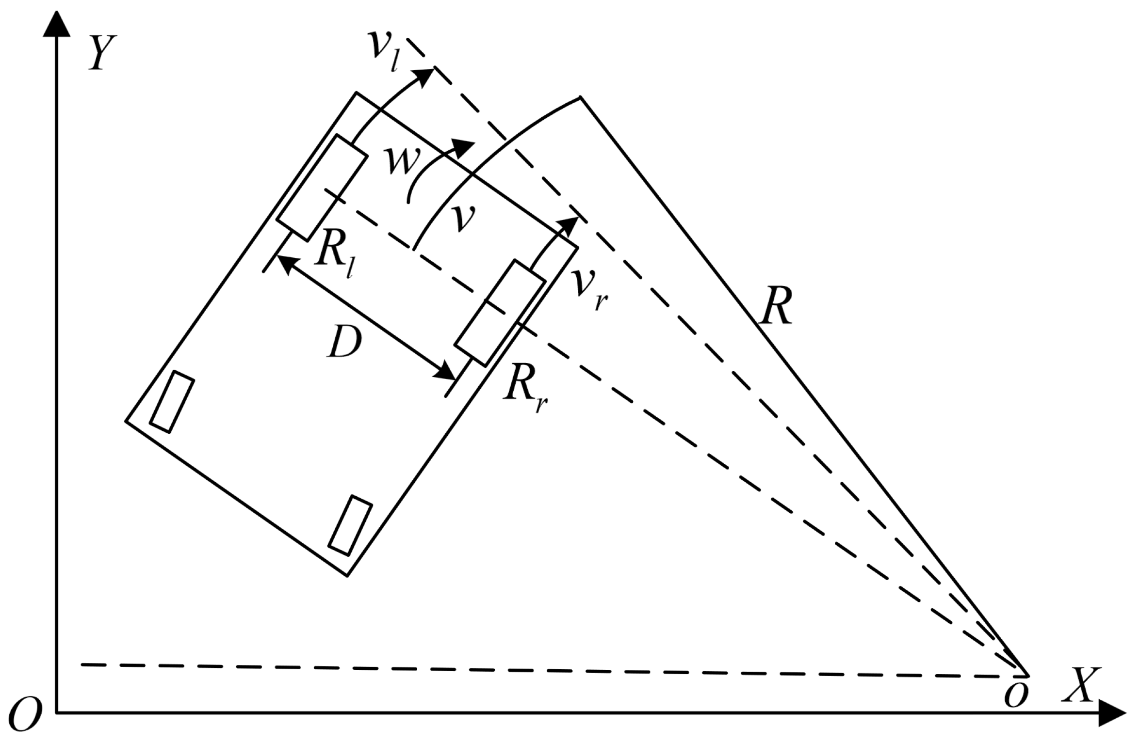
During the navigation process of the robot on open ground, the first step involves using RTK pose information as a prior pose. Simultaneously, the robot integrates motion measurements from the wheel encoders to match the estimated pose with the map features. The robot’s mobile base moves on the ground through differential drive motion, which is accomplished by assigning different speeds to its two wheels. The simplified differential drive motion model is depicted in Figure 11, with the world coordinate system defined as X O Y .
From the equation of circular motion, R = v ω , where the base is running at v, the angular velocity of rotation is ω , the center of rotation is o, the speed of the left driving wheel is v l , the speed of the right driving wheel is v r , and the radius of rotation of the cart is R. The sign of R is determined by the signs of v and ω . When R is positive, the center of the circle o is to the left of the base’s center of control. When R is negative, the center of the circle o is on the right side of the base’s control center. When R is 0, the base rotates in place, with the center of the circle o at the base’s control center. When R is ± , the base moves in a straight line, with the center of the circle at infinity to the left or right.
Assuming that the base is a rigid body connection, at that moment, the radius of the left driving wheel of the base from the center of rotation o is R l , the radius of the right driving wheel from the center of rotation o is R r , and the distance between the two driving wheels is D. Then, according to the relationship between rotational velocity and angular velocity, we can obtain ω = ω r = ω l , and since R l R r = D , we have the following:
ω r = v r R + D 2 , ω l = v l R D 2 v r = v + ω × D 2 , v l = v ω × D 2
Due to the symmetrical design of the two driving wheels on the base’s body, the following can be inferred:
ω = v r v l D , R = v r + v l D 2 v r v l
By considering the above Equation (2) for circular motion, it can be shown that
v = R ω = v r v l D × v r + v l D 2 v r v l = v r + v l 2
The real-time pose of the mobile base can be determined from this:
Δ x = X t + 1 X t = cos θ t × v × Δ t Δ y = Y t + 1 Y t = sin θ t × v × Δ t Δ θ = θ t + 1 θ t = ω × Δ t
where the current coordinates are ( X t + 1 , Y t + 1 , θ t + 1 , θ t + 1 ) , the coordinates of the previous moment are ( X t , Y t , θ t ) , and the time interval is Δ t .
After obtaining the estimated pose of RTK and wheeled odometry, the flow block diagram illustrating the fusion localization is presented in Figure 12:
The framework combines the pose information from odometry and RTK with the EKF. The EKF consists of two components: a prediction step and an update step. The pose information obtained from wheeled odometry serves as the input value for the prediction step, while the pose information acquired from RTK is used as the observation value for the update step.
Assuming that the robot base moves in a two-dimensional plane in the ground motion area, the state vector of the system can be represented by the base’s pose given the pose x k = X k , Y k , θ k at time k, where X k , Y k represent the geometric center position of the mobile robot and θ k represents the pose of the mobile robot in the navigation coordinate system.
  • State prediction
    The pose of the mobile robot at the moment t + 1 can be expressed as
    x k + 1 = f ( x k , u k + 1 ) + w k + 1
    In Equation (5), x k + 1 represents the state variable at time k + 1 . u k + 1 denotes the control input to the system at time k + 1 , while w k + 1 represents the motion noise at time k + 1 . Finally, f x k , u k + 1 represents the relationship between the state variables x k + 1 and x k .
    Prediction of the pose estimate at the moment k + 1 from the robot motion model:
    x ¯ k + 1 = x ^ k + Δ x Δ y Δ θ
    where x ¯ k + 1 is the estimated value of the positional attitude at the moment ( k + 1 ) predicted by the motion model, and x ^ k is the predicted value of the positional attitude at the moment k.
    The covariance matrix P ¯ k + 1 of the a priori estimates of the predicted state vector is
    P ¯ k + 1 = f x P k f x T + f w Q k + 1 f w T
    In Equation (7), P k and Q k + 1 represent the covariance matrices of the pose x k and process noise w k + 1 , respectively. f x and f w represent the Jacobian matrices of the motion model and the Jacobian matrix of the process noise, respectively.
  • State update.
    At time ( k + 1 ) , the observation model for the localization information provided by RTK can be obtained as follows:
    z k + 1 = X R T K Y R T K θ R T K + v k + 1
    In Equation (8), z k + 1 represents the system observation at time ( k + 1 ) , v k + 1 represents the observation noise at time ( k + 1 ) , and X R T K Y R T K θ R T K represents the pose values calculated by RTK.
    (1)
    Calculate the Kalman gain as follows:
    K k + 1 = P ¯ k + 1 h ¯ x h x P ¯ k + 1 h x T + R k + 1 1
    where K ( k + 1 ) represents the Kalman gain at time ( k + 1 ) ; h x represents the Jacobian matrix of the measurement model, which is known to be the identity matrix according to the observation model; and R ( k + 1 ) represents the covariance matrix of the observation noise, provided by the RTK pose conversion package.
    R k + 1 = σ X 0 0 0 σ Y 0 0 0 σ θ
    In Equation (10), σ X σ Y σ θ is the observed noise variance of the pose X Y and attitude θ of the RTK output, respectively.
    (2)
    A posteriori of the state variables.
    x ^ k + 1 = x ¯ k + 1 + K k + 1 z k + 1 x ¯ k + 1
    (3)
    Update the covariance matrix to be the posterior estimate covariance matrix of the state variables:
    P k + 1 = I 3 K k + 1 P ¯ k + 1
    In the equation, I 3 is the third-order unit matrix.
At this stage, the data fusion process of odometry and RTK is finalized. It should be noted that the RTK system is installed in the center of the base body’s driving wheels, while the odometry calculation uses the midpoint between the two driving wheels as the reference point. The outputted localization result from the EKF can be directly utilized as the localization input for the navigation planner, allowing for subsequent path tracking. The control block diagram of the navigation planner is illustrated in Figure 13:
By converting the control information of the robot base from navigation into the corresponding speeds of the left and right wheels, precise control of the robot base can be achieved in order to follow the planned trajectory. The software for ground navigation of the robot employs movebase as the fundamental framework. In order to find the shortest effective path, the A* algorithm is utilized as the global path planner. Once a feasible and optimal global path is generated by the A* algorithm, the TED algorithm (timed elastic band algorithm) is used as the local path planner to generate smooth and safe local paths.

3.2.2. Method for Near-Track Areas

In the near-track area, high-precision localization is required for the mobile base of a robot due to the high demand of track design for track error. At the same time, RTK devices experience more severe electromagnetic interference in the near-track area, which causes localization drift. Wheel odometry is prone to slippage on smooth surfaces, and vision-based pose estimation encounters difficulties in recognizing cooperative markers due to outdoor environmental contamination or shadow caused by sunlight. Additionally, the detection range of magnetic sensors is much smaller than other systems. Given these challenges, it is proposed to integrate RTK and wheel odometry, and further enhance the accuracy of the system’s pose estimation by utilizing vision and magnetic sensors.
The robot utilizes a magnetic sensor installed on the right side of the mobile base to detect the magnetic field above a magnetic strip. By comparing the collected signals of magnetic field intensity, when the magnetic strip is located below the sensor, the robot calculates its position and orientation. The relationship between the determined magnetic field intensity signals obtained by placing the magnetic strip below the sensor and the positional differences is then fitted into a function f to estimate the deviation in position and orientation. The calculation process can be summarized as follows:
x m a g y m a g = f ( S 1 , S 2 , , S n )
where S i represents the magnetic field intensity signal collected at the nth sampling point vertically inside the magnetic field sensor above the magnetic strip, and ( x m a g , y m a g ) represents the positional deviation of the magnetic strip with respect to the magnetic field sensor. The converted positional relationship of this pose to the current position of the base can be expressed as
x r o b o t y r o b o t θ r o b o t = T × x m a g y m a g 0
where ( x r o b o t , y r o b o t , θ r o b o t ) represents the current pose of the robot’s base and T represents the transformation matrix from the sensor coordinate system to the base coordinate system.
The robot utilizes visual pose estimation, which involves employing a high-definition monocular camera installed at the middle position of the front side of the base. This camera is used to recognize AprilTag cooperative markers. First, the pose of the camera in the base coordinate system is determined and represented by a transformation matrix T r o b o t C . Through a visual detection algorithm, we can obtain the pose of the cooperative marker in the camera coordinate system, which is represented by a transformation matrix T C t a g . The expressions for these transformations are as follows:
T r o b o t C = R r o b o t C t r o b o t C 0 1 × 3 1 , T C t a g = R C t a g t C t a g 0 1 × 3 1
where R r o b o t C , R C t a g represents the rotational matrix for the corresponding posture, and t r o b o t C , t C t a g represents the translation vector for the corresponding position.
To obtain the pose of the base in the collaborative sign coordinate system, we first calculate the pose of the camera in the collaborative sign coordinate system. Then, we use composite transformation to calculate the pose of the base in the collaborative sign coordinate system, represented by the transformation matrix T t a g r o b o t . The calculation formula is as follows:
T t a g r o b o t = T t a g C T r o b o t C = R C t a g T R r o b o t C R C t a g T t r o b o t C R C t a g T t C t a g 0 1 × 3 1
Based on the use of vision and magnetic sensor to generate pose estimation, the fusion localization is then combined with RTK and wheel odometry. The schematic diagram of the fusion localization is shown in Figure 14.
This framework builds upon the use of an EKF to fuse the localization information provided by odometry and RTK. In addition, it incorporates the fusion of magnetic sensor and vision estimated pose information using a new EKF. The prediction and update steps in this framework differ from the previous framework. The previous moment’s information of the magnetic sensors and vision estimated pose are used as input values for the prediction step to generate the current prediction state estimation, while the measurements obtained from the two actual sensors at the current moment serve as the observation values for the update step. Furthermore, prior to the EKF process, the estimated pose, generated by weighted calculations based on sensor characteristics, is adjusted to minimize the impact of robot motion speed and the distance of collaborative identification on pose estimation. Subsequently, the pose estimation results are aligned to the RTK navigation coordinate system, taking into account the measurement covariance of RTK. Finally, a weighted fusion is performed to obtain the final estimated pose. The generated pose estimate is used as input for the navigation planner, allowing for path following and ultimately reaching the entrance of the mechanical gear-track. This process is consistent with the ground segment.

3.3. On-Track Localization and Compliance Driving Method

The on-track pose estimation method is essential for ensuring the safety of mobile manipulator during aerial operations and serves as the foundation for the compliance navigation of the robot through curved track segments. To simplify the issue, we abstract the gear movements of the robot base as a simple mechanical structure consisting of a thin rod connecting two pulleys at the front and rear, as illustrated in Figure 15. The following stages represent key steps that the robot must undergo for precise pose computation during the climbing process. The estimation of pose on the track can be divided into the following steps:
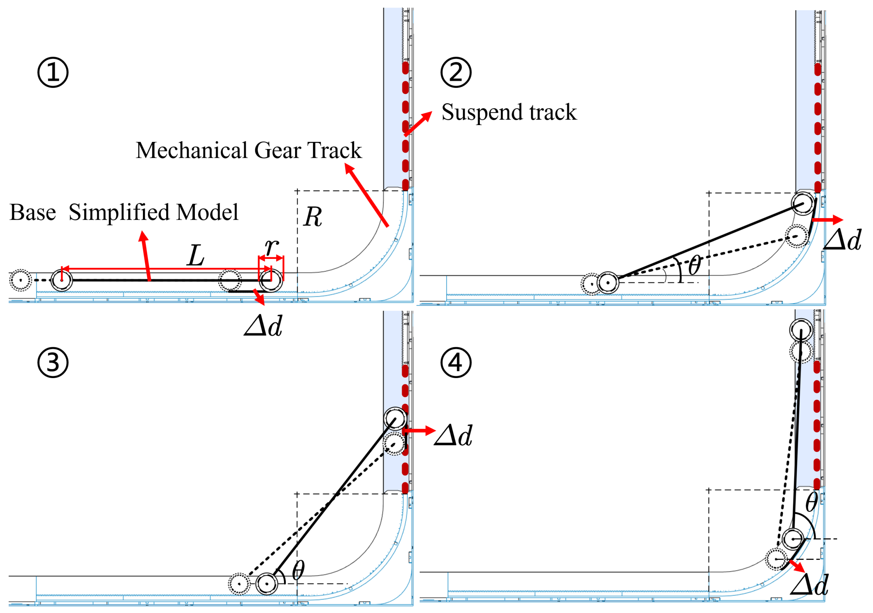
  • When the robot enters the gear-track from the horizontal plane without entering the curved track, its current pose can be simply represented as
    θ = 0 , y = Δ d , z = 0 , θ 1 = θ , y 1 = y , z 1 = z
    In this context, the base pitch angle is denoted as θ , the distance that the center of mass of the base moves forward relative to the starting point of the rack is denoted as y, and the elevation height of the base center of mass is denoted as z. The arc length traversed by the gear during the time interval Δ t is denoted as Δ d . The pose information for the first three stages is recorded to facilitate the calculation of poses in the subsequent stage, with the pitch angles designated as θ 1 , θ 2 , θ 3 and the positions as y 1 , z 1 ; y 2 , z 2 ; y 3 , z 3 .
  • Subsequently, the front drive gear enters the curved track. Due to constraints in mechanical design, the rear drive gear remains on the horizontal track. At this point, considering the continuity of motion and neglecting the minor distance discrepancies caused by the bending of the rack, let the diameter of the drive gear be denoted as r and the spacing between the two drive gears as L. The designed curved track is effectively a segment of a circle with a radius denoted as R. Thus, denoting the variable as D = R r 2 , the following relationship can be established:
    θ = arcsin ( D D cos Δ d R L )
    and it can be concluded that the current pose is
    y = y 1 + Δ d L cos θ 1 cos θ 2 , z = L sin θ + r 2 , θ 2 = θ , y 2 = y , z 2 = z
  • As the front gear traverses the curved track, the rear gear remains on the horizontal track, thereby yielding the following result:
    θ = arccos ( L cos ( θ 2 ) Δ d L )
    and it can be concluded that the current pose is
    y = y 2 + Δ d L cos θ 2 cos θ 2 , z = L sin θ + r 2 , θ 3 = θ , y 3 = y , z 3 = z
  • As the front gear traverses the suspended segment of the track, the rear gear will move onto the curved track. Similarly, by neglecting the minor distance differences caused by the slight deformation of the rack due to bending, the following result can be obtained:
    θ = arccos ( D D sin ( Δ d R ) L )
    and it can be concluded that the current pose is
    y = y 3 + L cos θ 3 cos θ 2 z = z 3 + Δ d L sin θ 3 sin θ 2
In the mechanical structure design of this study, the curvature characteristics of the curved track in the bending section require the gears to travel along a curved trajectory, resulting in a longer path compared to the straight horizontal track where the other gear is located. Additionally, the gears need to overcome additional lateral forces caused by the curved track. To avoid dangerous situations such as jamming and base bending when passing through the curved track, we have developed a gear compliance driving control method. The core advantage of this method lies in its ability to allocate different control strategies and adjust the torque of the corresponding driving gears in real time based on the robot’s real-time operating status on the track, effectively addressing interference factors such as interrupted racks and dynamic changes in posture under complex working conditions.
Specifically, based on the calculation of the on-track pose, the control of the front and rear gear motors is decoupled into three primary strategies: a dual-gear position synchronization control mode, a supervisory position control for the front gear, and a supervisory position control for the rear gear. The allocation of strategies and torque control is primarily determined by the following situations:
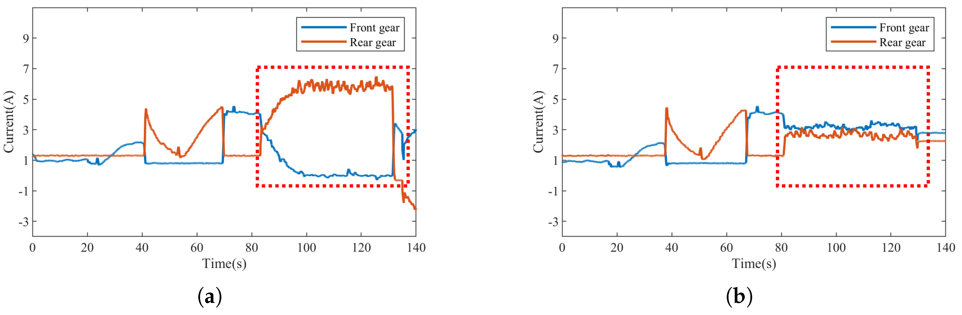
  • When the robot begins to ascend at a level where the front gear can still provide effective driving force, the front gear operates at a constant speed while the rear gear adjusts its torque through an adaptive controller. This adjustment is made in real-time, based on the curvature of the curve and the current speed of the robot, thereby altering the driving current of the rear gear.
  • When the front gear of the robot transitions to a suspended state and loses driving force, the rear gear provides the necessary driving force. During this period, the front gear will undergo a process of transitioning from suspension to contact with the rack. The adaptive controller adjusts the driving current of the front gear in real-time based on the distribution of the interruption points in the track and the current speed of the robot to match the driving speed of the rear gear.
  • Ultimately, the front gear will continuously operate on a vertical track, while the rear gear will experience a process of transitioning from suspension to contact with the rack. It is essential to monitor the control current of the front driving gear at a constant speed to ensure the rear driving gear matches this current appropriately.
  • In the final ascent motion, both driving gears are positioned on the vertical track, and the driving current of the rear gear is adjusted in real-time to match that of the front gear, ensuring coordinated and stable rotation, thereby achieving a steady state of ascent.
The adaptive adjustment of motor torque primarily involves calculating the required torque for the motor. Subsequently, the relationship between the driving torque and driving current is roughly established through calculations. Torque control of the driving motor is then achieved by adjusting the control current of the driving motor. As illustrated in Figure 16, a simple controller has been constructed. In this control process, an initial estimation of the required torque for the driven gear is made based on the current generated when another driving gear operates at a specific position. Afterward, the control torque is mapped to the control current, and a proportional–derivative (PD) controller is designed. Through real-time monitoring and feedback adjustment, the control current of the driven gear can quickly and accurately respond to the dynamic changes required by the system, ensuring that the operational state of the driven gear remains within the optimal control range. Ultimately, the control objective is to ensure that the control torque of the driven gear closely follows the change trend of the control torque of the driving gear, achieving coordinated operation between the two and, thus, facilitating the compliance control of the geared drive system.

4. Experiments and Conclusions

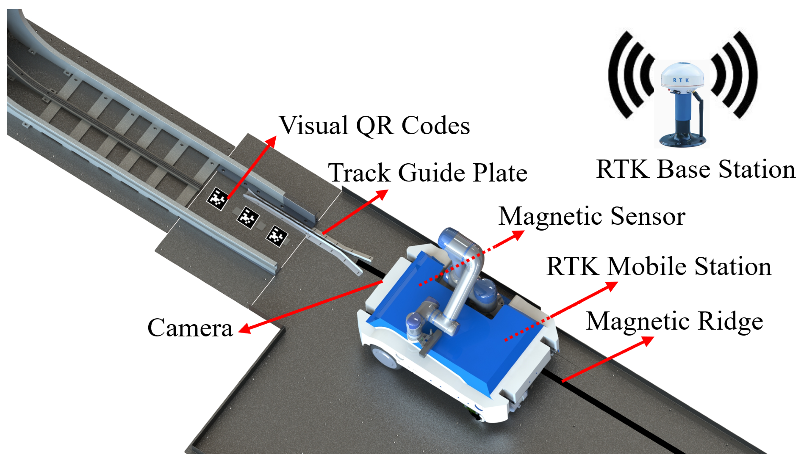
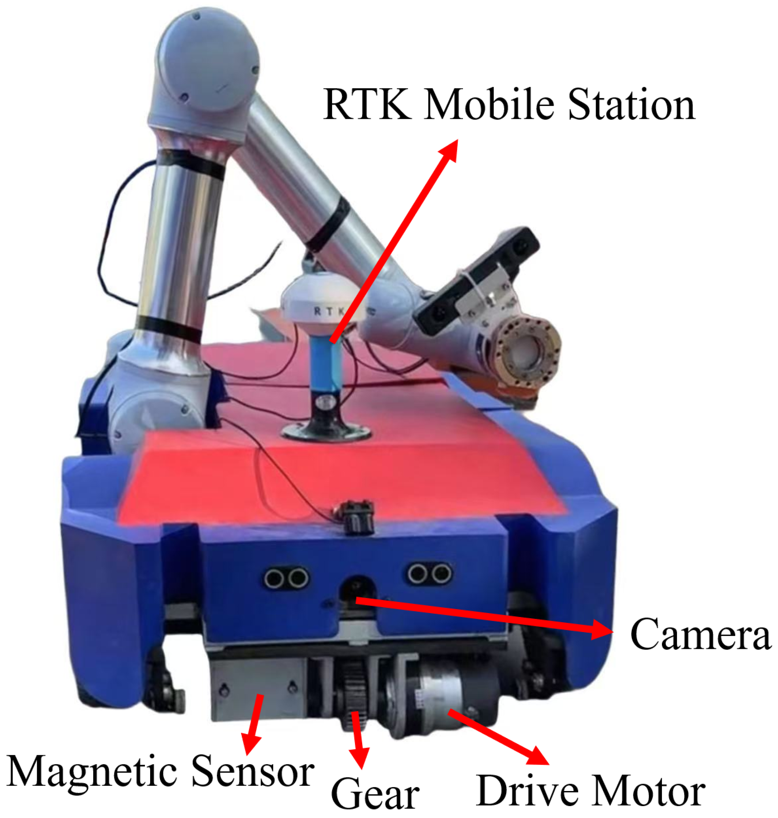
4.1. Experimental Hardware Composition

As illustrated in Figure 17, the overall hardware composition of the robot primarily includes the power system, mechanical arm system, mobile base drive system, and core control system. It is evident that sensors, including the camera, magnetic sensor, and RTK system, are predominantly installed on the frontal aspect of the mobile base. The selected camera has a focal length of 3.24 mm, a field of view of H: 100° and V: 56°, and supports automatic exposure and white balance control. The magnetic sensor features an 8-point signal output, with a length of 19.2 mm and a magnetic point spacing of 10 mm. The RTK positioning system is a full-range RTK system, with a nominal horizontal accuracy of 2 cm and a vertical accuracy of 4 cm. The gear motor’s encoder has a resolution of 17 bits.

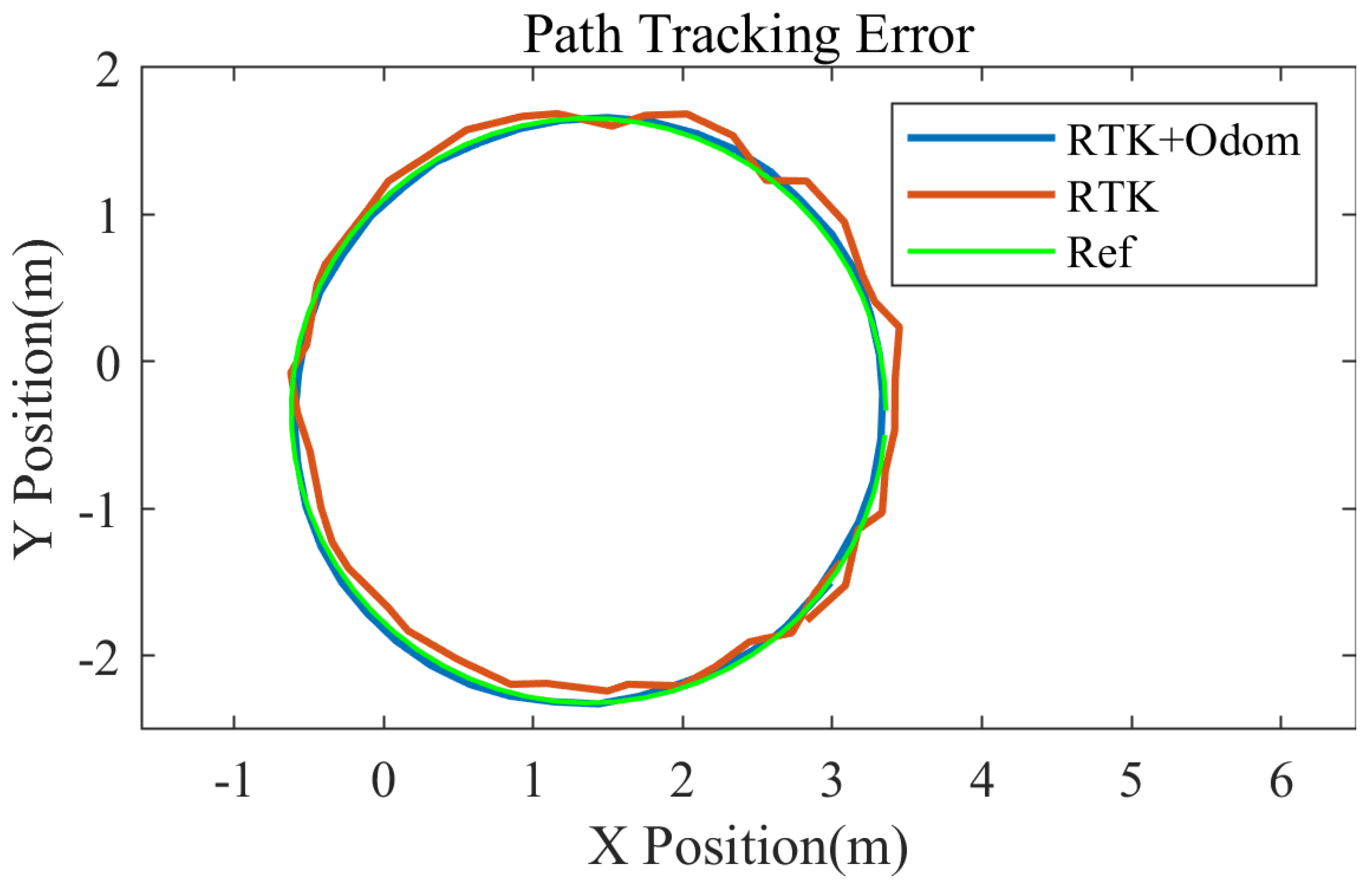
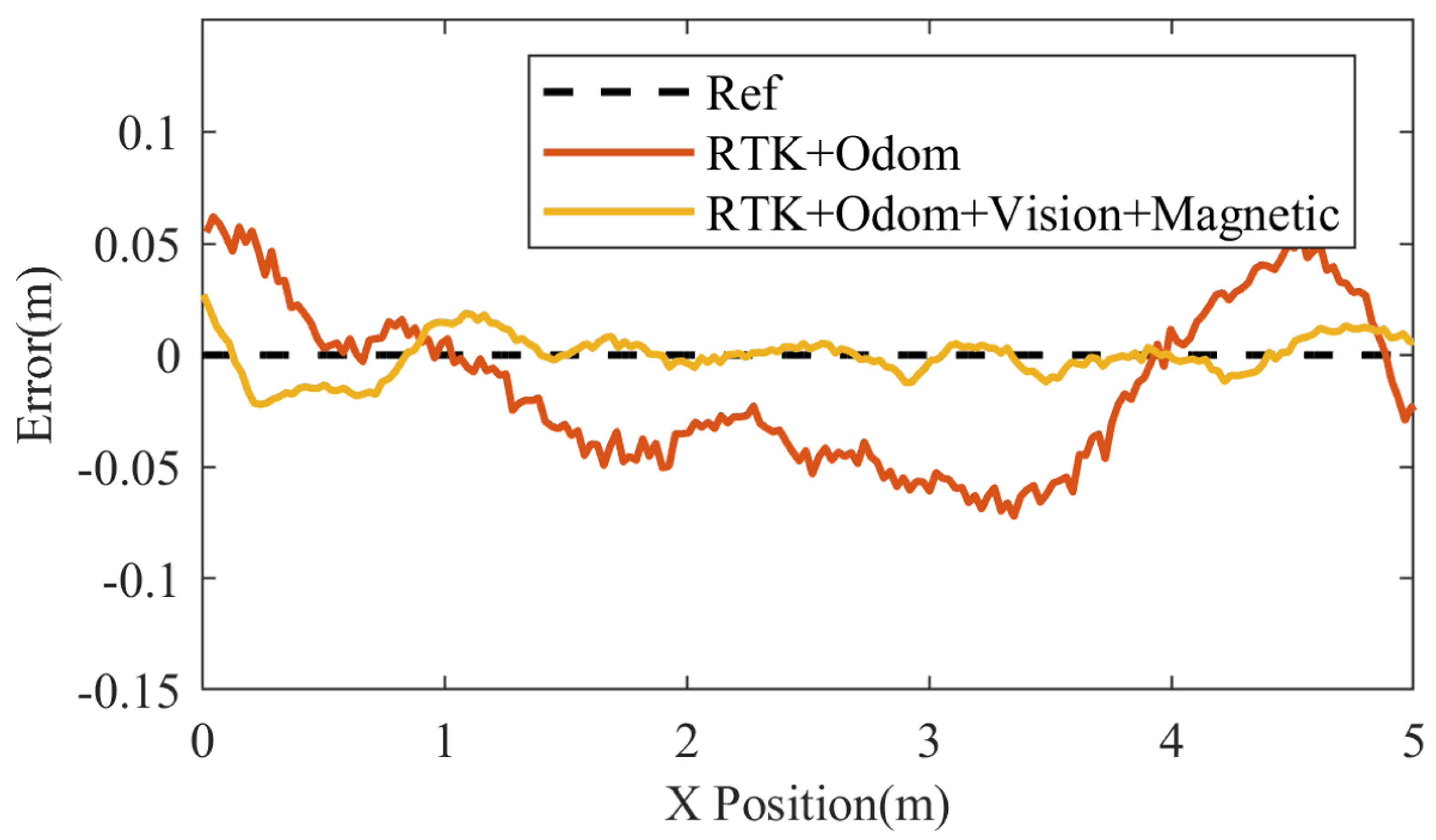
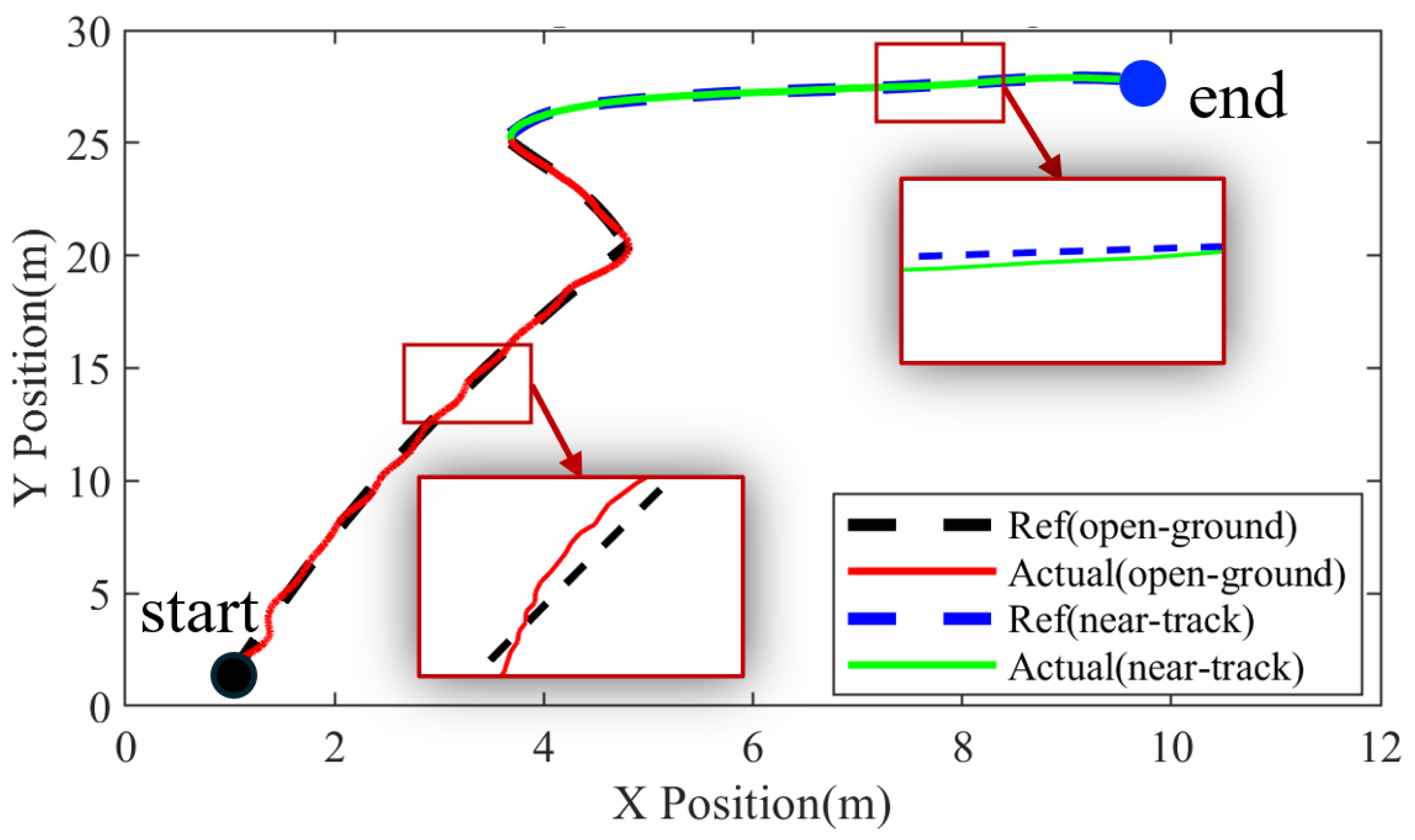
4.2. Ground Navigation Experiments

This experiment validates the effectiveness of the proposed multi-sensor fusion navigation control method for mobile base through practical navigation experiments conducted by a robot in open ground areas and in narrow spaces in the near-track area.
The experimental environment contains large signal bases, and the robotic arm mounted on the robot generates significant electromagnetic interference during operation, which substantially affects the localization accuracy of the RTK equipment. In this context, a tracking experiment for the mobile base along a specified circular trajectory with a radius of approximately 2 m was conducted. The circular trajectory possesses geometric characteristics of uniformity and periodicity, enabling a comprehensive assessment of the localization accuracy of the mobile base during continuous variation, as depicted in Figure 18. In the experiment, a comparative analysis was performed by utilizing RTK alone and by fusion of RTK with odometry information to evaluate their localization and navigation performance. Figure 19 presents the localization trajectory results obtained from the different methods. It is evident that the trajectory using the fused localization closely aligns with the reference trajectory, whereas the trajectory obtained using RTK separately exhibits significant deviations at certain points, leading to localization drift. Furthermore, due to the limited localization frequency of the RTK equipment, the pose estimation results can exhibit abrupt changes, resulting in increased instability in localization and path planning. Conversely, the fused approach, which integrates continuous odometry information, yields relatively smooth pose estimation results, minimizing the occurrence of abrupt changes.
The second experimental scenario takes place in a narrow area prior to entering the track, as shown in Figure 20. Due to the strong shielding and reflective properties of iron-based steel plates on electromagnetic waves, the localization performance of the RTK device in this environment is significantly less stable compared to typical ground environments. Additionally, the coefficient of friction between the robot’s differential wheels and the steel plate is substantially reduced, leading to an increase in odometry errors. The experiment compared two different localization fusion methods: the fusion of RTK and odometry, and the fusion of RTK, odometry, vision, and magnetic information. The experimental results are presented in Figure 21. In the RTK and odometry fusion approach, limited by the strong interference in the narrow area, the pose error can reach up to 6 cm. However, when vision and magnetic information are further integrated, they provide additional environmental perception dimensions for the robot, effectively compensating for the shortcomings of RTK and odometry. Even when the RTK signal is subjected to strong interference, the system can still assist the robot in achieving precise localization through feature matching and tracking. Experimental validation confirmed that this method has a maximum error of only 3 cm, demonstrating greater adaptability and resilience to interference.
Additionally, the effectiveness of using vision or magnetic information independently within the fusion scheme was verified. Experimental results indicate that if vision information is discarded, the limitations in pose accuracy of both the RTK and odometry, compounded by the restricted detection range of the magnetic sensor, are significant. Specifically, if the robot’s poses deviate, and it does not return to the detection range of the magnetic sensor, the robot’s deviation will progressively increase. Conversely, if magnetic information is not utilized, the reliance on a continuously placed cooperative marker on the ground may lead to localization failure if one of the markers becomes damaged or obscured by strong shadows caused by sunlight affecting the camera’s performance.
Based on these experiments, it can be concluded that the multi-sensor fusion localization and navigation method proposed in this paper demonstrates high localization accuracy and reliability in practical applications. Figure 22 illustrates the complete ground navigation planning results for a robot conducted in an outdoor environment. It can be observed that the robot accurately follows the designated path, particularly in areas requiring higher precision and stability, thereby meeting the demands of the task.

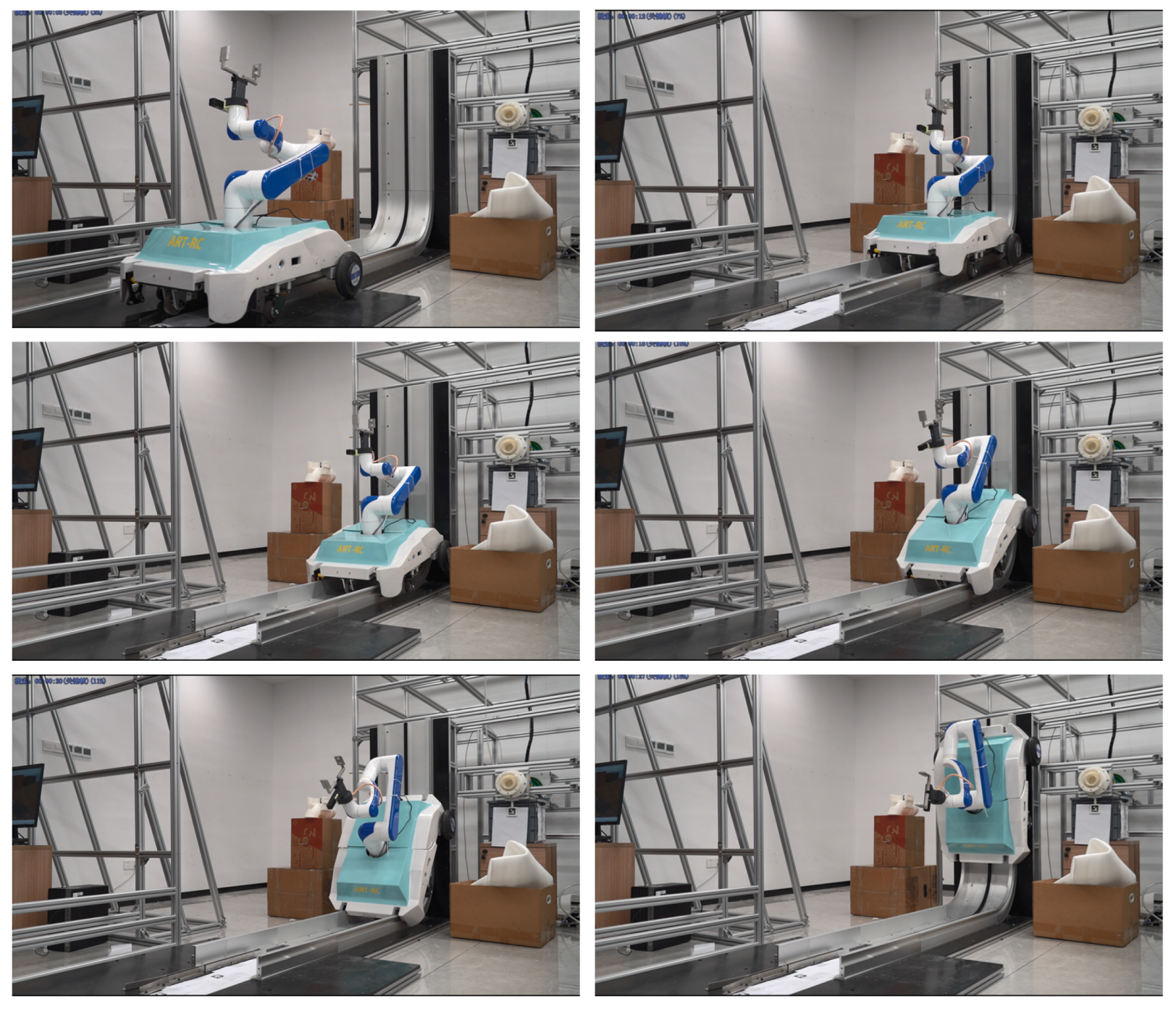
4.3. Gear-Track Climbing Experiments

In the laboratory, we constructed a simulated track system that utilizes a continuous rack as its main structural component. To test the performance of the independently designed mechanical gear-track, we selected a mobile base to execute climbing actions on the mechanical gear-track. This approach allows us to accurately verify the track’s passability during actual operations and its stability during climbing. As illustrated in Figure 23, we monitored the mobile base’s trajectory, velocity variations, and power output parameters in real time during the experiment. The results indicate that the mobile base can smoothly and reliably transition from a horizontal motion state to a vertical climbing state using the designed mechanical gear-track. Furthermore, the material strength and motion precision of the designed mechanical track and climbing gear assembly meet the climbing requirements, demonstrating good stability and adaptability throughout the entire process.
Furthermore, we specifically focus on the motion performance of the proposed track localization method and the gear compliance control method in the curved track sections. Therefore, we conducted experiments on a real outdoor track, as shown in Figure 24. Initially, we compared the height of the base measured in actual stages with calculated values. Subsequently, we observed the attitude adjustment of the mobile base during cornering and monitored the current variation of the two driving motors in real-time. Due to the use of conventional control methods, the mobile base was unable to navigate the curved track smoothly, resulting in potential irreversible mechanical damage. To ensure experimental safety, we conducted comparative experiments during the vertical ascent phase of the mobile base, employing both the gear compliance drive control method and a method without it. This allowed us to analyze the practical effects of the proposed cornering track compliance control strategy, with the experimental results presented in Figure 25.
Figure 25a presents the experimental results using the compliance control method, while Figure 25b shows the experimental results without using this method. The experimental data demonstrate significant differences. In the results without the use of compliance control for the gear, there are objective errors due to the mechanical characteristics of the gear engaging with the mechanical track and the control of the gear motor. As a result, there are slight positional deviations between the front and rear driving gears of the base when climbing the track. Furthermore, since the two gears are connected by a rigid body and the two driving motors do not have the ability to adjust torque, these small positional differences will be significantly amplified into differences in driving torque. This ultimately leads to a continuous increase in the control current difference between the two gear driving motors, severely affecting the climbing stability and reliability of the base. However, by using the compliance control method for the gear, it is possible to make the control current of the compliance gear approach that of the active gear to a certain extent, effectively ensuring a dynamic balance of torque between the two driving wheels and providing a more stable performance for the climbing process of the base.

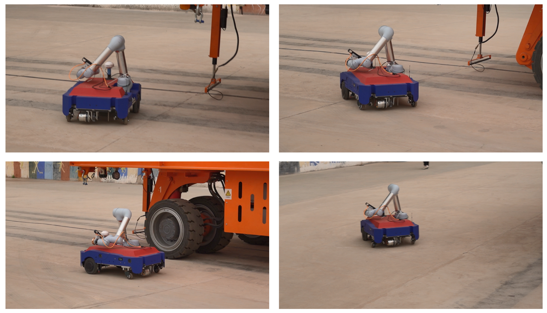
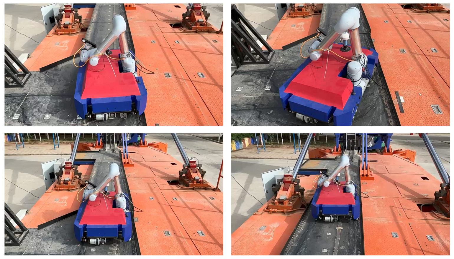
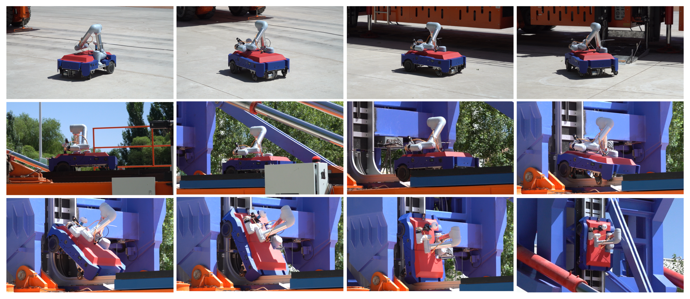
4.4. Complete Tasks’ Experiments

After completing the ground navigation experiments and gear-track climbing experiments, we conducted a comprehensive task flow experiment outdoors, in which the robot transitioned from ground initiation to climbing to a high altitude for operational tasks, which is shown in Figure 26. Throughout this process, real-time monitoring and data collection of the robot’s operational status in a complex and variable outdoor environment allowed us to effectively validate the proposed system’s exceptional capabilities in the field of work-at-height operations. These capabilities include precise positioning and stable operational ability in complex outdoor environments, adaptive adjustment capabilities in response to complex meteorological conditions and external disturbances, as well as sustained stable operational performance during prolonged high-intensity tasks. Figure 1 illustrates the robot we designed performing actual tasks at a high altitude.

5. Conclusions

This paper presents a novel mobile manipulator base and a corresponding mechanical gear-track, equipped with a flexible operating mechanical arm. It innovatively proposes a localization and navigation control method based on multi-sensor fusion, as well as a compliance control method for gear-climbing, addressing the associated technical challenges. Ultimately, the effectiveness of the proposed system is validated through a series of diverse experiments. The successful validation of these capabilities underscores the substantial application value of the system across various scenarios, including the cleaning of building exteriors, vertical material handling in industrial automated production lines, and exploration of work-at-height terrains. This system effectively enhances the operational range and adaptability of robots, establishing a robust foundation for their future widespread application and promotion within related industries. It is anticipated to significantly improve operational efficiency, reduce labor costs, and ensure operational safety, thereby fostering technological innovation and industrial advancement in the domain of working at heights.

Author Contributions

L.F. and Y.Z. conceptualized the research. H.W. and C.G. developed the robot, conducted the simulations and experiments, and wrote the manuscript. H.W. processed the data. G.L., T.S. and X.S. supported the experiments. L.F. and Y.Z. supervised the study. All authors have read and approved the manuscript.

Funding

This paper was supported by Intelligent Aerospace System Leading Innovation Team Program of Zhejiang (Grant No. 2022R01003) and Intelligent Robot Cluster Project of Jiuquan Satellite Launch Center.

Data Availability Statement

The data presented in this study are available on request from the corresponding author.

Conflicts of Interest

The authors declare no conflicts of interest.

References

  1. Sandakalum, T.; Ang, M.H., Jr. Motion planning for mobile manipulators—A systematic review. Machines 2022, 10, 97. [Google Scholar] [CrossRef]
  2. Sun, F.; Chen, Y.; Wu, Y.; Li, L.; Ren, X. Motion planning and cooperative manipulation for mobile robots with dual arms. IEEE Trans. Emerg. Top. Comput. Intell. 2022, 6, 1345–1356. [Google Scholar]
  3. Honerkamp, D.; Büchner, M.; Despinoy, F.; Welschehold, T.; Valada, A. Language-grounded dynamic scene graphs for interactive object search with mobile manipulation. IEEE Robot. Autom. Lett. 2024, 9, 8298–8305. [Google Scholar] [CrossRef]
  4. Ding, L.; Xing, H.; Torabi, A.; Mehr, J.K.; Sharifi, M.; Gao, H.; Mushahwar, V.K.; Tavakoli, M. Intelligent assistance for older adults via an admittance-controlled wheeled mobile manipulator with task-dependent end-effectors. Mechatronics 2022, 85, 102821. [Google Scholar]
  5. Thakar, S.; Malhan, R.K.; Bhatt, P.M.; Gupta, S.K. Area-coverage planning for spray-based surface disinfection with a mobile manipulator. Robot. Auton. Syst. 2022, 147, 103920. [Google Scholar]
  6. Piyapunsutti, S.; De Guzman, E.L.; Chaichaowarat, R. Navigating Mobile Manipulator Robot for Restaurant Application Using Open-Source Software. In Proceedings of the 2023 IEEE International Conference on Robotics and Biomimetics (ROBIO), Koh Samui, Thailand, 4–9 December 2023; IEEE: Piscataway, NJ, USA, 2023; pp. 1–6. [Google Scholar]
  7. Tadakuma, K.; Tadakuma, R.; Nagatani, K.; Yoshida, K.; Peters, S.; Udengaard, M.; Iagnemma, K. Crawler vehicle with circular cross-section unit to realize sideways motion. In Proceedings of the 2008 IEEE/RSJ International Conference on Intelligent Robots and Systems, Nice, France, 22–26 September 2008; IEEE: Piscataway, NJ, USA, 2008; pp. 2422–2428. [Google Scholar]
  8. Tadakuma, K.; Tadakuma, R.; Kinoshita, H.; Nagatani, K.; Yoshida, K.; Udengaard, M.; Iagnemma, K. Mechanical design of cylindrical track for sideways motion. In Proceedings of the 2008 IEEE International Conference on Mechatronics and Automation, Takamatsu, Japan, 5–8 August 2008; IEEE: Piscataway, NJ, USA, 2008; pp. 161–167. [Google Scholar]
  9. Ernits, R.M.; Hoppe, N.; Kuznetsov, I.; Uriarte, C.; Freitag, M. A new omnidirectional track drive system for off-road vehicles. In Proceedings of the XXII International Conference on Material Handling, Constructions and Logistics, Belgrade, Serbia, 4–6 October 2017. [Google Scholar]
  10. Fiedeń, M.; Bałchanowski, J. A mobile robot with omnidirectional tracks—Design and experimental research. Appl. Sci. 2021, 11, 11778. [Google Scholar] [CrossRef]
  11. Xiao, Y.; Yan, Y.; Yu, Y.; Wang, B.; Liang, Y. Research on pose adaptive correction method of indoor rail mounted inspection robot in GIS Substation. Energy Rep. 2022, 8, 696–705. [Google Scholar]
  12. Masuda, N.; Khalil, M.M.; Toda, S.; Takayama, K.; Kanada, A.; Mashimo, T. A Suspended Pollination Robot with a Flexible Multi-Degrees-of-Freedom Manipulator for Self-Pollinated Plants. IEEE Access 2024, 12, 142449–142458. [Google Scholar] [CrossRef]
  13. Xu, Y.; Liu, Y.; Liu, X.; Wang, B.; Zhang, L.; Nie, Z. Research on motion planning system for wall-climbing mobile manipulator for large steel structures welding operation. Ind. Robot. Int. J. Robot. Res. Appl. 2024, 52, 73–83. [Google Scholar]
  14. Liu, Y.; Wang, H.; Hu, C.; Zhou, Q.; Li, P. A Spiny Climbing Robot with Dual-Rail Mechanism. Biomimetics 2023, 8, 14. [Google Scholar] [CrossRef] [PubMed]
  15. Ganz, S.; Käber, Y.; Adler, P. Measuring tree height with remote sensing—A comparison of photogrammetric and LiDAR data with different field measurements. Forests 2019, 10, 694. [Google Scholar] [CrossRef]
  16. Kim, H.; Hyun, C.U.; Park, H.D.; Cha, J. Image mapping accuracy evaluation using UAV with standalone, differential (RTK), and PPP GNSS positioning techniques in an abandoned mine site. Sensors 2023, 23, 5858. [Google Scholar] [CrossRef] [PubMed]
  17. Rix, B.; Nebeling, A.; Raab, T. Distance measurement using near infrared sensors. In Proceedings of the Energy Consumption and Autonomous Driving: Proceedings of the 3rd CESA Automotive Electronics Congress, Paris, France, 3–4 December 2014; Springer: Berlin/Heidelberg, Germany, 2016; pp. 177–189. [Google Scholar]
  18. Štibinger, P.; Broughton, G.; Majer, F.; Rozsypálek, Z.; Wang, A.; Jindal, K.; Zhou, A.; Thakur, D.; Loianno, G.; Krajník, T.; et al. Mobile manipulator for autonomous localization, grasping and precise placement of construction material in a semi-structured environment. IEEE Robot. Autom. Lett. 2021, 6, 2595–2602. [Google Scholar]
  19. Basiri, M.; Gonçalves, J.; Rosa, J.; Bettencourt, R.; Vale, A.; Lima, P.U. A multipurpose mobile manipulator for autonomous firefighting and construction of outdoor structures. Field Robot. 2021, 1, 102–126. [Google Scholar]
  20. Pastor, F.; Ruiz-Ruiz, F.J.; Gómez-de Gabriel, J.M.; García-Cerezo, A.J. Autonomous wristband placement in a moving hand for victims in search and rescue scenarios with a mobile manipulator. IEEE Robot. Autom. Lett. 2022, 7, 11871–11878. [Google Scholar] [CrossRef]
  21. Cui, B.; Zhang, J.; Wei, X.; Cui, X.; Sun, Z.; Zhao, Y.; Liu, Y. Improved Information Fusion for Agricultural Machinery Navigation Based on Context-Constrained Kalman Filter and Dual-Antenna RTK. In Proceedings of the Actuators, Wiesbaden, Germany, 13–14 June 2024; MDPI: Basel, Switzerland, 2024; Volume 13, p. 160. [Google Scholar]
  22. Woo, H.J.; Yoon, B.J.; Cho, B.G.; Kim, J.H. Research into navigation algorithm for unmanned ground vehicle using real time kinemtatic (RTK)-GPS. In Proceedings of the 2009 ICCAS-SICE, Fukuoka, Japan, 18–21 August 2009; IEEE: Piscataway, NJ, USA, 2009; pp. 2425–2428. [Google Scholar]
  23. Feng, Y.; Wang, J. GPS RTK performance characteristics and analysis. Positioning 2008, 1, 1–8. [Google Scholar] [CrossRef]
  24. Valente, D.S.M.; Momin, A.; Grift, T.; Hansen, A. Accuracy and precision evaluation of two low-cost RTK global navigation satellite systems. Comput. Electron. Agric. 2020, 168, 105142. [Google Scholar] [CrossRef]
Figure 1. Our mobile manipulator robots with novel base design perform high-altitude tasks, mitigate human labor risks, and enhance operational efficiency.
Machines 13 00288 g001
Figure 2. Robot mobile base integrates driving wheels, sensors, power supply, and central 6-DOF robotic arm. Unique wheel system combines differential wheels and driven gears for motion control.
Machines 13 00288 g002
Figure 3. Mobile manipulator and track system: the robot enters the gear-track from the ground and then transitions from horizontal to vertical movement along the track, enabling autonomous operations at elevated heights.
Machines 13 00288 g003
Figure 4. Foldable mechanical gear-track with approximately 0–90° folding range; enhances mobility and adaptability to diverse worksite conditions compared to fixed tracks.
Machines 13 00288 g004
Figure 5. The detailed design of the mechanical gear-track and its entry guidance mechanism.
Machines 13 00288 g005
Figure 6. Mechanical gear-track backward–forward tolerance and suspended track design.
Machines 13 00288 g006
Figure 7. Mechanical gear-climbing mechanism design: Rubber tires restrict radial movement relative to the guide rail, while universal balls limit lateral deviation. Universal balls are mounted slightly wider than the guide rail, leveraging rubber tires’ elasticity to generate preload in the constrained direction and eliminate motion clearance.
Machines 13 00288 g007
Figure 8. Traction mechanism for mobile base climbing track. High-power motor drives gear engagement with track, enabling vertical motion and start–stop. Motor connected to self-locking gear via flange shaft.
Machines 13 00288 g008
Figure 9. Localization and control framework: Ground multi-sensor fusion integrates RTK (10 Hz), camera (30 Hz), and magnetic sensor and odometry (50 Hz). Pose estimation results are generated at 10 Hz for real-time path planning and control commands. On-track localization uses a 50 Hz gear encoder to generate pose estimates and match control strategies for gear motor actuation.
Machines 13 00288 g009
Figure 10. Multi-sensor fusion integrates vision, magnetic sensor, RTK, and wheel odometry.
Machines 13 00288 g010
Figure 11. Two-wheel kinematics simplified model.
Machines 13 00288 g011
Figure 12. RTK and odometry fusion localization flow block diagram.
Machines 13 00288 g012
Figure 13. Navigation framework.
Machines 13 00288 g013
Figure 14. Schematic of RTK, odometry, vision, and magnetic fusion framework.
Machines 13 00288 g014
Figure 15. The stages of the base passing through the curved track.
Machines 13 00288 g015
Figure 16. Gear motor compliance control framework.
Machines 13 00288 g016
Figure 17. Mobile manipulator multi-sensors and gear driver composition.
Machines 13 00288 g017
Figure 18. Experiment for open-ground localization and navigation.
Machines 13 00288 g018
Figure 19. Result of circular trajectory tracking using two methods on the open-ground.
Machines 13 00288 g019
Figure 20. Experiment for near-track localization and navigation.
Machines 13 00288 g020
Figure 21. Result of linear trajectory tracking using two methods on the near-track.
Machines 13 00288 g021
Figure 22. Experimental result of the complete ground localization and navigation.
Machines 13 00288 g022
Figure 23. Experimental verification for climbing on gear-track in the laboratory.
Machines 13 00288 g023
Figure 24. Experiment of the base climbing on outdoor track.
Machines 13 00288 g024
Figure 25. Experimental results of two methods used in the vertical climb phase. (a) Experimental results of vertical phase using conventional drive method. (b) Experimental results of vertical phase using the drive method described in the article.
Machines 13 00288 g025
Figure 26. Experiment of complete task.
Machines 13 00288 g026
Disclaimer/Publisher’s Note: The statements, opinions and data contained in all publications are solely those of the individual author(s) and contributor(s) and not of MDPI and/or the editor(s). MDPI and/or the editor(s) disclaim responsibility for any injury to people or property resulting from any ideas, methods, instructions or products referred to in the content.

