Abstract
This paper presents the design and implementation of the motion controller and adaptive interface for the second generation of the UCF-MANUS intelligent assistive robotic manipulator system. Based on extensive user studies of the system, several features were implemented in the interface that could reduce the complexity of the human–robot interaction while also compensating for the deficits in different human factors, such as working memory, response inhibition, processing speed, depth perception, spatial awareness, and contrast sensitivity. To effectively and safely control the robotic arm, we designed several new features, including an adaptive human–robot interaction framework. To provide the user with a less complex and safer interaction with the robot, we added new functionalities such as ‘One-click mode’, ‘Move suggestion mode’, and ‘Gripper Control Assistant’. Furthermore, to equip our assistive robotic system with an adaptive User Interface, we designed and implemented compensators such as ‘Contrast Enhancement’, ‘Object Proximity Velocity Reduction’, and ‘Orientation Indicator’. Results from a multitude of experiments show that the system is indeed robust, safe, and computationally efficient in addition to addressing the user’s highly desired capabilities.
1. Introduction
Assistive robotic technologies are increasingly being used to compensate for limitations in cognitive and/or motor functions to boost the autonomy and quality of life of persons with disabilities. In addition, they significantly improve the ability of such individuals to perform activities of daily living (ADLs), including food preparation and eating, object retrieval and placement, personal hygiene and grooming, dressing, etc. As such, there is a growing importance given to continually studying and advancing the major components of assistive robotic systems, including sensory and feedback systems, control systems, manipulators, user interfaces, speed and efficiency of software architectures, and human–robot interaction (HRI). To effectively address this growing need, extensive user studies must be carried out to ensure the usability of assistive robots; these user studies form a strong foundation from which assistive robotic systems evolve to convincingly meet the needs of people with disabilities and allow for intelligent human–robot interaction.
Traditionally, robotic assistive devices have offered human-interface modalities such as joysticks and touchscreens. For individuals with severe disabilities, multimodal body-machine interfaces for body and head-motion control have been proposed [1]. This interface is equipped with a wearable and wireless body sensor network to support inertial measurement units (IMUs) and surface electromyography (sEMG) sensor nodes and translate the upper-body gestures to control commands. There are other control modalities for efficient human–robot interaction, such as the utilization of eye gaze [2,3]. The significance of such modalities is often challenged by the usability difficulties assistive technologies present, especially for individuals who may have upper-body, extremity, or cognitive limitations [4,5].
In robotic arm manipulators, such as the ARM (Assistive Robotic Manipulator), users are required to control the movement of multiple (up to seven) arm segments and the opening and closing of the gripper segment attached to the end-effector. Even though this provides a great degree of flexibility, redundancy, and versatility for performing reaching motions and object retrieval tasks, it requires the ability to control a large number of degrees of freedom. For many users, this presents excessive cognitive loads which makes the whole experience tedious and frustrating. To reduce such complexity associated with controlling robotic devices, some researchers have pursued automation to address this problem [6,7,8,9,10,11,12]. In these studies, a user is required to select an object on a touchscreen, and the robotic arm retrieves the item completely on its own. To further reduce the manual control complexity, the authors of [13] proposed a novel orientation control algorithm that is more intuitive for a broad range of users; instead of using the original setting of the end-effector coordinate frame, the authors define an adaptive end-effector coordinate frame for generating the end-effector angular motion. Usability testing of this approach showed that the task errors and processing times are significantly lower than the original orientation control. In another study [14], an automatic control mode switching algorithm was proposed for the manual control of an assistive robot. Based on a time-optimal model, this study concluded that Dijkstra’s algorithm can be used to predict when the robot should automatically change modes for the user. Although it is not possible to discuss all the rich related literature in Assistive Robotics, we refer the interested reader to a collection of books, reviews, and journal and conference articles [15,16,17,18,19,20,21,22,23,24,25,26,27,28,29,30,31,32,33,34,35,36,37,38,39,40,41].
Although the above methods eliminated some of the user limitations, they did not address the need for independence, which has been shown to be a highly desired ability among targeted users. Previous research by our research group has shown that disabled individuals prefer to retain control over the robotic arm as they have already lost a large measure of control over their environments. Specifically, we have found that users prefer to interact with the robot rather than to cede control to the autonomous functions of the robot. Complete autonomous systems are also shown to be strictly not preferred by the users because they tend to be sub-optimal and/or error-prone because of technological limitations. In addition, in separate studies, we identified visual, cognitive, and physical abilities as critical human factors that affect the performance of a user’s interaction with robotic assistants. Specifically, it was found that a decrease in dexterity, processing speed, spatial ability, visual ability, and working memory can result in difficulty interacting with assistive technology, resulting in increased time on task and higher loading, contributing to users’ frustration and a degraded sense of autonomy.
The aforementioned challenges and empirical discussions of human factors in engineering and research in [42] have motivated us to design the second generation of UCF-MANUS with a focus on interactive control. This work builds on and improves the autonomous functionality built into the first generation of the UCF-MANUS [6,7]. The flexible autonomy framework pursued here allows users to completely assume the robot control functionality or share workload collaboratively with an intelligent robotic software agent imbued with autonomy and situational awareness. Moreover, the needs, abilities, and limitations of assistive robot users are also evaluated and applied to the design of the assistive robot system, developing a system that is cognizant of the user needs and can carry out tasks effectively, safely, and with minimal physical and cognitive workload. Our proposed solution also presents an adaptive user interface (UI) that offers multiple control modalities and compensations customizable to each user’s individual preference for level of interactivity as well as perceptual, cognitive, and physical limitations. The work here is novel in the sense that it presents a unique sliding autonomy assistive robotic system driven in part by underlying Lyapunov-based nonlinear control design and novel algorithms for situationally aware robotic systems based on state-of-the-art vision, depth, and haptic sensing.
The remainder of the paper is organized as follows. In Section 2, the system hardware and software architecture is presented. In Section 3, we present the design and implementation of the object estimation and motion controller. The adaptive interface design and implementation overlaid on the bottom layer discussed in Section 3 is presented in Section 4. In Section 5, we present results and analysis from performance comparison of the manual and assistive control modes. A discussion of the results is presented in Section 6 while Section 7 concludes the paper.
2. System Hardware and Software Architecture
2.1. System Hardware
2.1.1. Manipulator
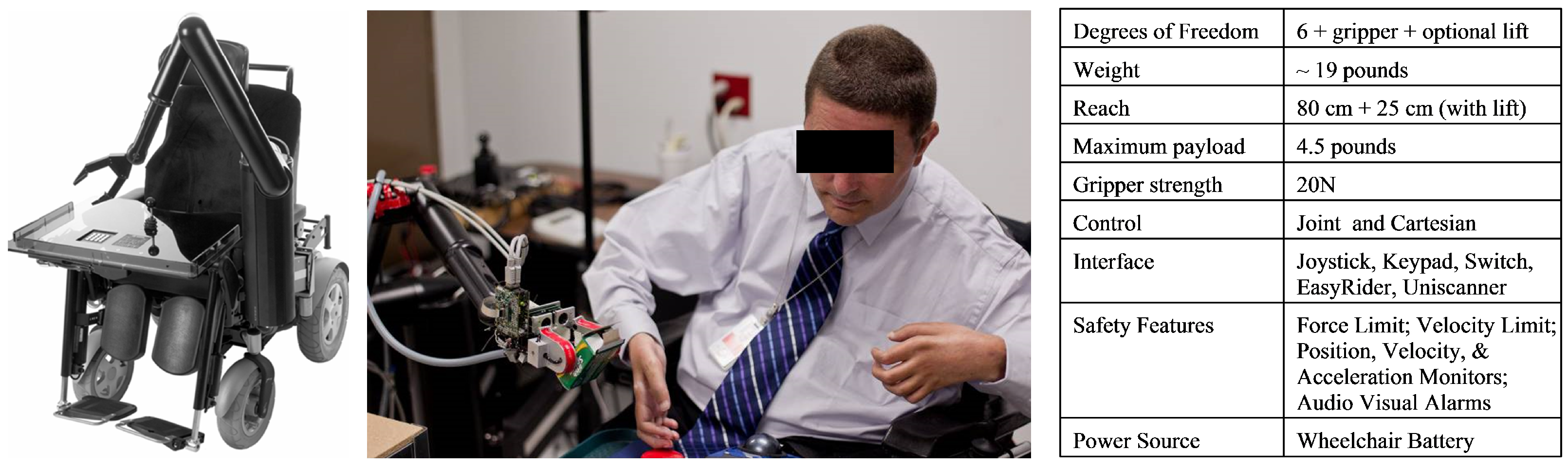
The UCF-MANUS assistive robotic system functions in a variable workspace and an unstructured environment and performs tasks that are highly desired by users, such as picking up a variety of objects from floor or shelves as well as carrying objects [43]. As can be seen in Figure 1, our assistive robotic system is based on the ARM (Assistive Robotic Manipulator) manufactured by Exact Dynamics. The ARM is a robotic arm that assists people with severe disabilities in their upper limbs. It weighs ~19 lbs. It can carry up to 4.5 lbs of weight in its gripper. It has six translational and rotational degrees of freedom that allow the robot to maintain the orientation of a grasped object while bringing it back to the user. The gripper has two hinged fingertips covered with anti-slip material to allow a firm grasp of almost any object. In addition, the ARM provides a Cartesian-coordinate-based control in which three principal axes of control are linear and orthogonal. This allows movement in a straight line besides joint-based control that is responsible for rotational movements. Furthermore, the ARM can be interfaced with a keypad, a joystick, or even a computer via its CAN interface.
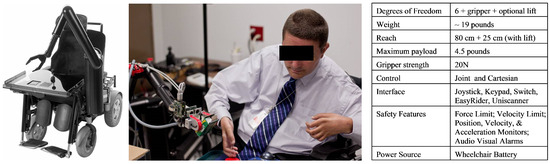
Figure 1.
Manus ARM mounted on a wheelchair (left), a quadriplegic user demonstrating the use of the UCF-MANUS in UCF’s Assistive Robotics Laboratory (middle) [picture used with permission from UCF News and Information], and table of specifications for the ARM (right).
2.1.2. Sensing
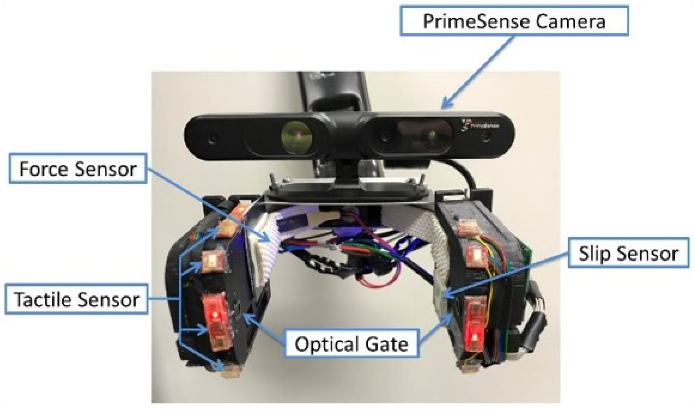
For the second generation of the UCF-MANUS, we updated the sensing system on the gripper. As shown in Figure 2, the gripper system has several embedded sensors for vision, tactile, force, object slippage, etc. We used the PrimeSense RGBD Camera to provide a color 3D view of the scene to the user and a depth map for the robot system (indicating the information relating to the distance of the surfaces of scene objects from a viewpoint). Using ABS Plastic material, 3D-printed frames attach around the two fingers of the bare MANUS ARM gripper. The frames were designed with appropriately sized cavities and channels for mounting and wiring various sensors. The mounted sensors include: (a) Force sensor mounted on the right finger of the gripper, providing the applied grasping force to the object; (b) LASER sensor-based slip sensor inserted in the left gripper finger for detecting the slippage between the object and the gripper [44]; (c) Two sets of optical gates embedded in the gripper fingers for detecting position of object inside gripper; (d) Two sets of tactile sensors mounted along both sides of the gripper for providing collision information between the gripper and its environment.
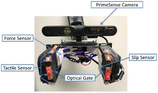
Figure 2.
Sensor embedded gripper with 3D PrimeSense Camera (RGB+D), Force-Sensing Resistor (FSR), Laser-based Slip Sensor, Tactile (touch) Sensors, and Optical Gates.
2.2. Software Architecture
The overall software architecture is altered from the previous generation [7] to account for additional modules. C/C++ is employed to implement all the necessary software modules in the Microsoft Visual Studio integrated development environment. Besides the compatible libraries utilized in the first generation, additional libraries such as OpenNI and OpenCV2 have been added to manage the video stream and to facilitate better image processing. The middleware of the system still employs the server-client communication protocol using TCP/IP sockets. The server directly communicates with the sensing hardware as well as the GUI and the vision computational modules all of which are treated as clients. The protocol provides an easy mechanism to add or remove a client without affecting the remaining components. However, since sockets-based communication requires making copies of the data packets, it is not used for high bandwidth data transfers, e.g., video frames are shared between different processes through mapped memory—thus, these types of data are restricted to be local to the machine with the attached visual sensing hardware. Figure 3 shows a schematic of the overall system integration for UCF-MANUS.
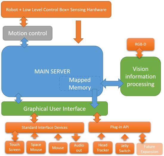
Figure 3.
UCF-MANUS Software Architecture.
3. Assistive Controller Design and Implementation
According to previous usability research, fully autonomous functionality is not entirely appealing to the user. This propelled us to update the technology and the framework to enable sliding-scale autonomy during human–robot interaction. Under the modified human–robot interaction framework, the user can take over robot control at any time except for special situations. For example, when an object being grasped by the robot is slipping through its gripper fingers, and the latency inherent in transferring control to the user or seeking user permission would lead to irretrievable loss of the object from within the fingers of the gripper, the robot controller is granted primacy for a limited time window lasting several seconds. The fully manual control and fully autonomous control modes available in the first-generation UCF-MANUS [6,7] represent the extrema for the flexible HRI framework adopted in this work. The application of advanced sensing and algorithms employed in the current generation allows the user to select a desired level of autonomy on the sliding scale between the two aforementioned limits.
3.1. Motion Control for Safe Grasping
When the object is acquired within the fingers of the gripper, the following process is carried out to apply the minimum force required to immobilize the object. Since ADL activities require interaction with novel objects, the exact amount of gripping force is not known in advance. If the grasping force is too little, the object may slip away; on the other hand, if the grasping force is too much, the gripper could crush the object. Based on these needs, we designed an adaptive algorithm for determining optimal grasping force [44]. This algorithm enables the robot to grasp different objects without crushing or dropping the object. By utilizing a Lyapunov-based analysis, we designed the control law for gripper finger velocity as follows
where is the applied gripper force, is the desired grasping force, is the grasping force error, and is the object slip velocity, while
are auxiliary signals. This leads to the following closed-loop dynamics for the object slip velocity and the force error
Here, are parameter estimates that are dynamically updated as follows:
where are control gains. To prove stability, we define a positive-definite function as follows:
where denotes an estimation error for the particular parameter. After differentiating (7) along (1), (2), (3) and (4), simplifying, and rearranging terms, we obtain
Motivated by the structure of the bracketed terms in (8), the adaptive update laws for and can be designed as follows
where, as similarly done above, we can utilize a projection algorithm (e.g., see [45]) to ensure that . Substituting of (9) and (10) in (8) produces a negative semi-definite expression for as follows:
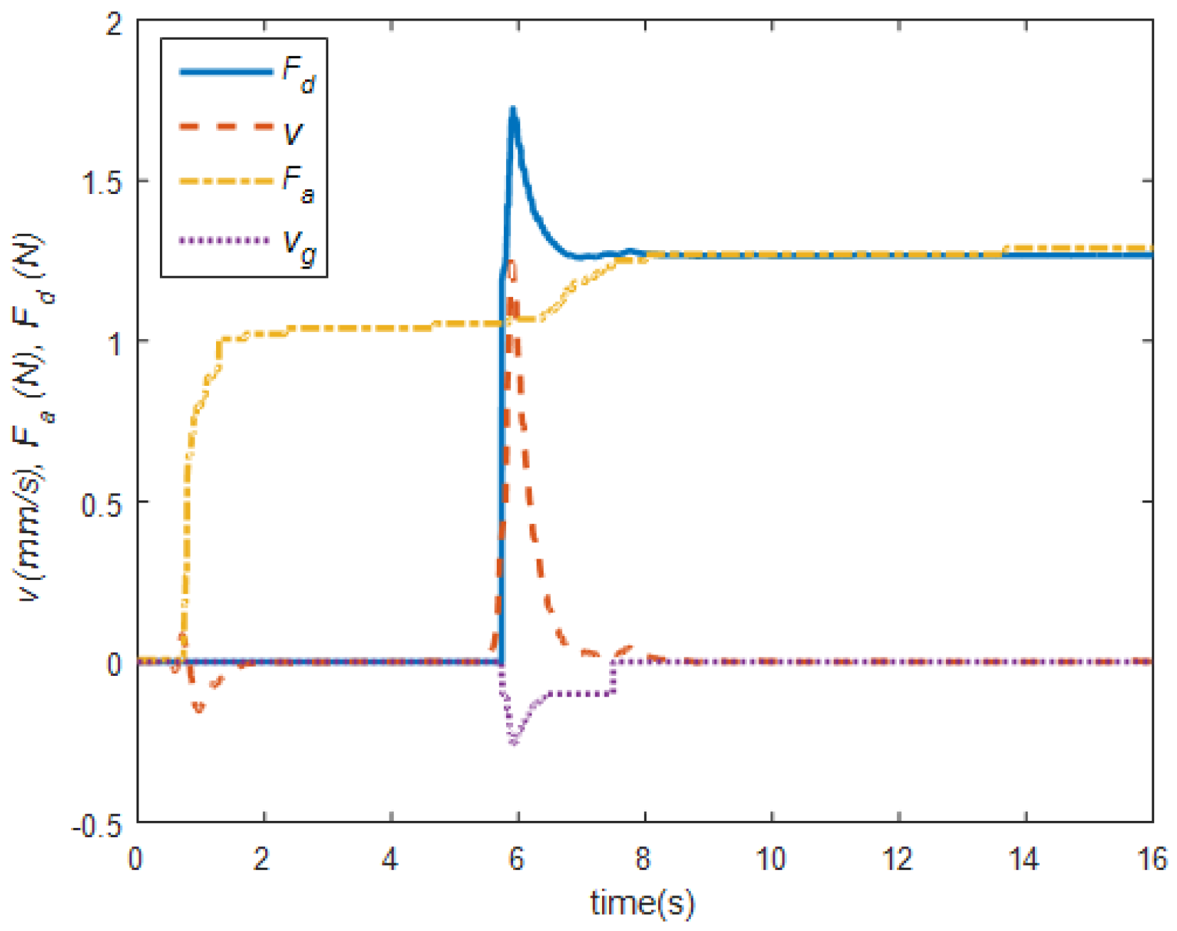
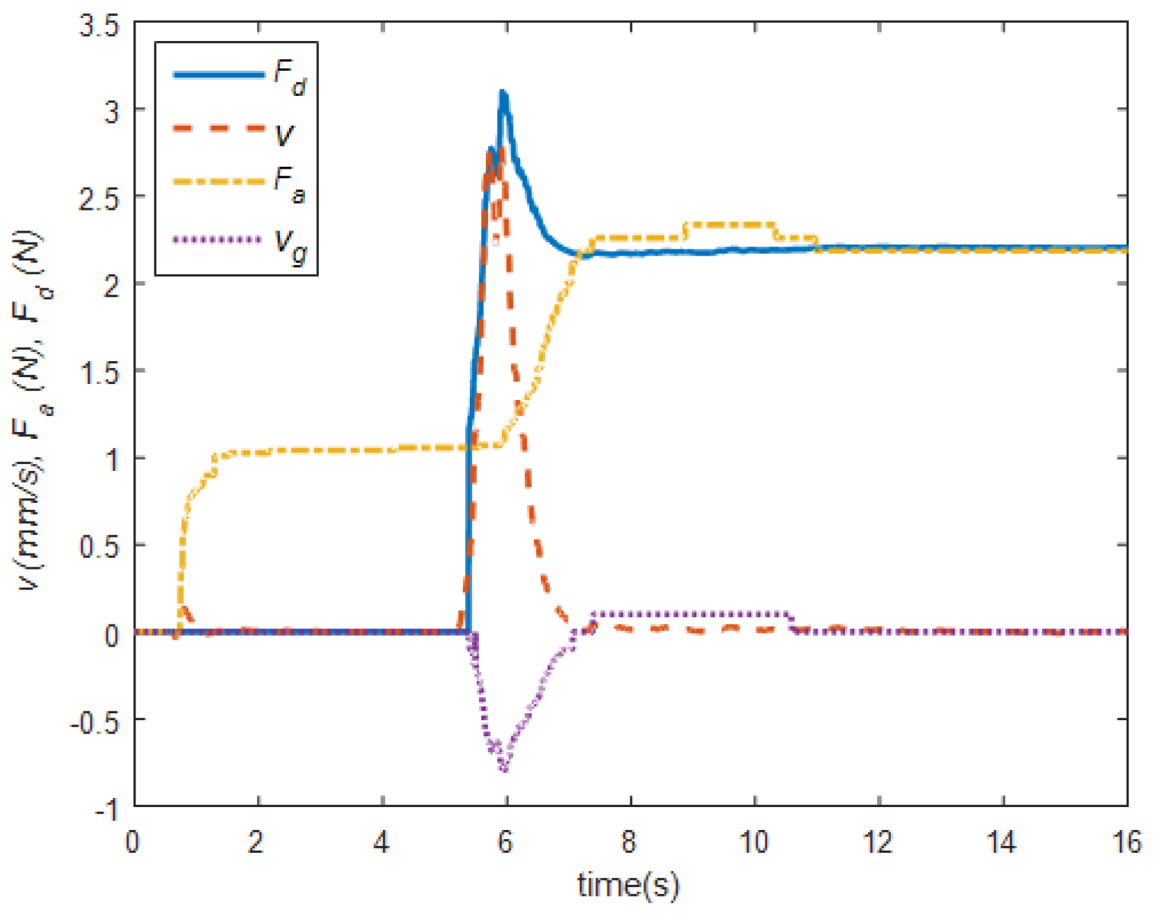
It is clear to see from (7) and (11) that while . Based on previous assertions, it is also clear to see from (1) and (2) that . Thus, one can utilize Barbalat’s Lemma [46] to prove that . From Figure 4 and Figure 5, we can see that the proposed adaptive grasping force controller can successfully stop the slippage and regrasp target objects. Figure 6 demonstrates the deformation difference between hardware-limited grasping, a flatness-based open-loop adaptive algorithm applied in the first-generation UCF-MANUS, and the closed-loop adaptive algorithm described here. A video showing the initial grasping, slip detection, and adaptive regrasping has been made available online [47].
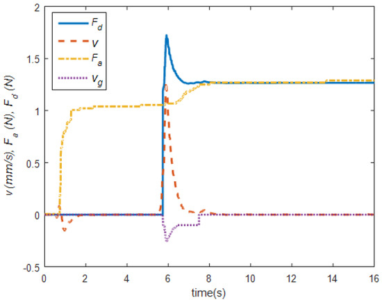
Figure 4.
Slip detection and regrasping of a half-filled water bottle. The initial grasping stage lasts between t = 0 s and t = 5.4 s using an initial grasp force of 1.05 N. Robot starts lifting the bottle at t = 5.4 s and the algorithm detects slipping at t = 5.7 s at which time the proposed closed-loop adaptive algorithm activates to stop slipping using final grasping force of 1.26 N [44].
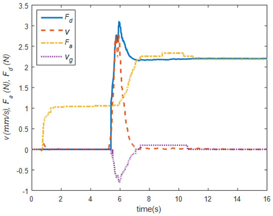
Figure 5.
Slip detection and regrasping of a fully filled water bottle. Initial grasping stage lasts between t = 0 s and t = 5 s using an initial grasp force of 1.05 N. Robot starts lifting the bottle and slipping is detected at t = 5.7 s at which time the proposed closed-loop adaptive algorithm activates to stop slipping using final grasping force of 2.2 N [44].
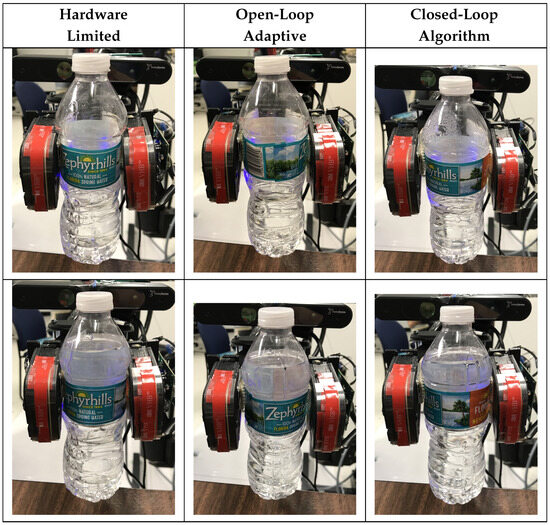
Figure 6.
Half (top) and full Water Bottle (bottom) being grasped with no force control algorithm (left), open-loop adaptive grasping (middle), and proposed grasping algorithm (right) [44].
3.2. 6-DOF Pose Estimation
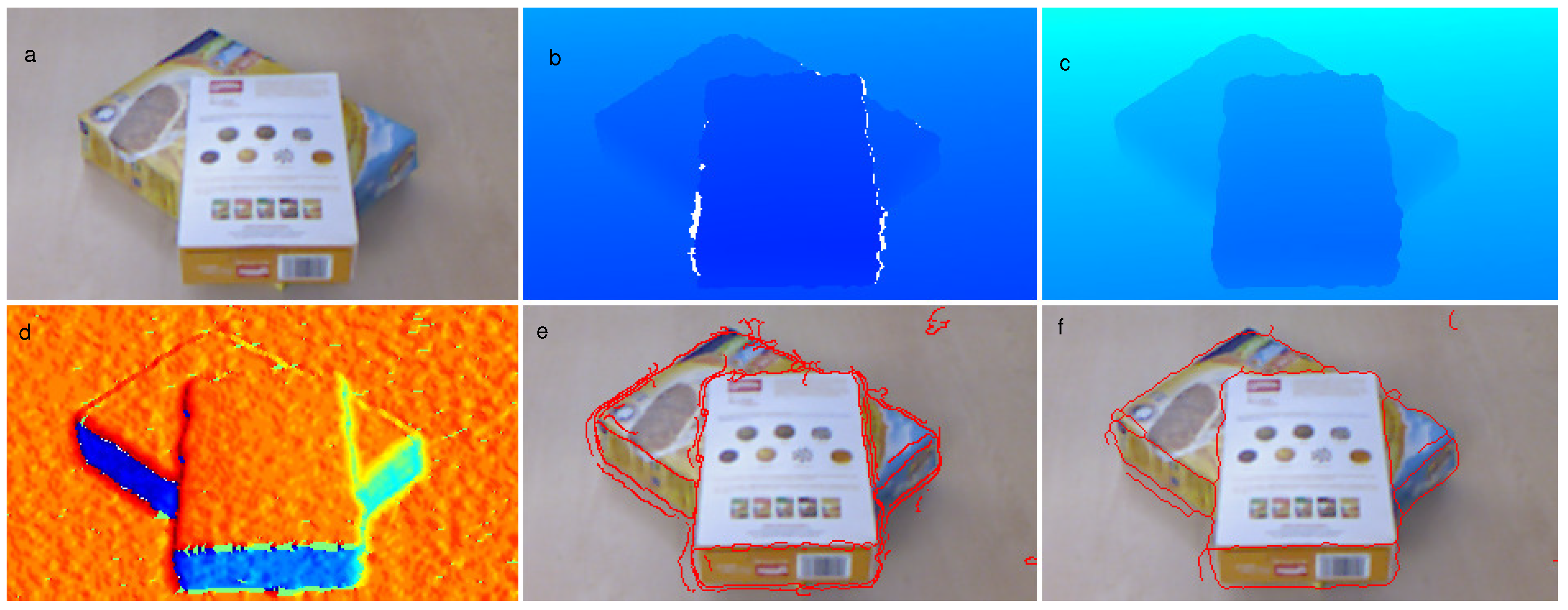
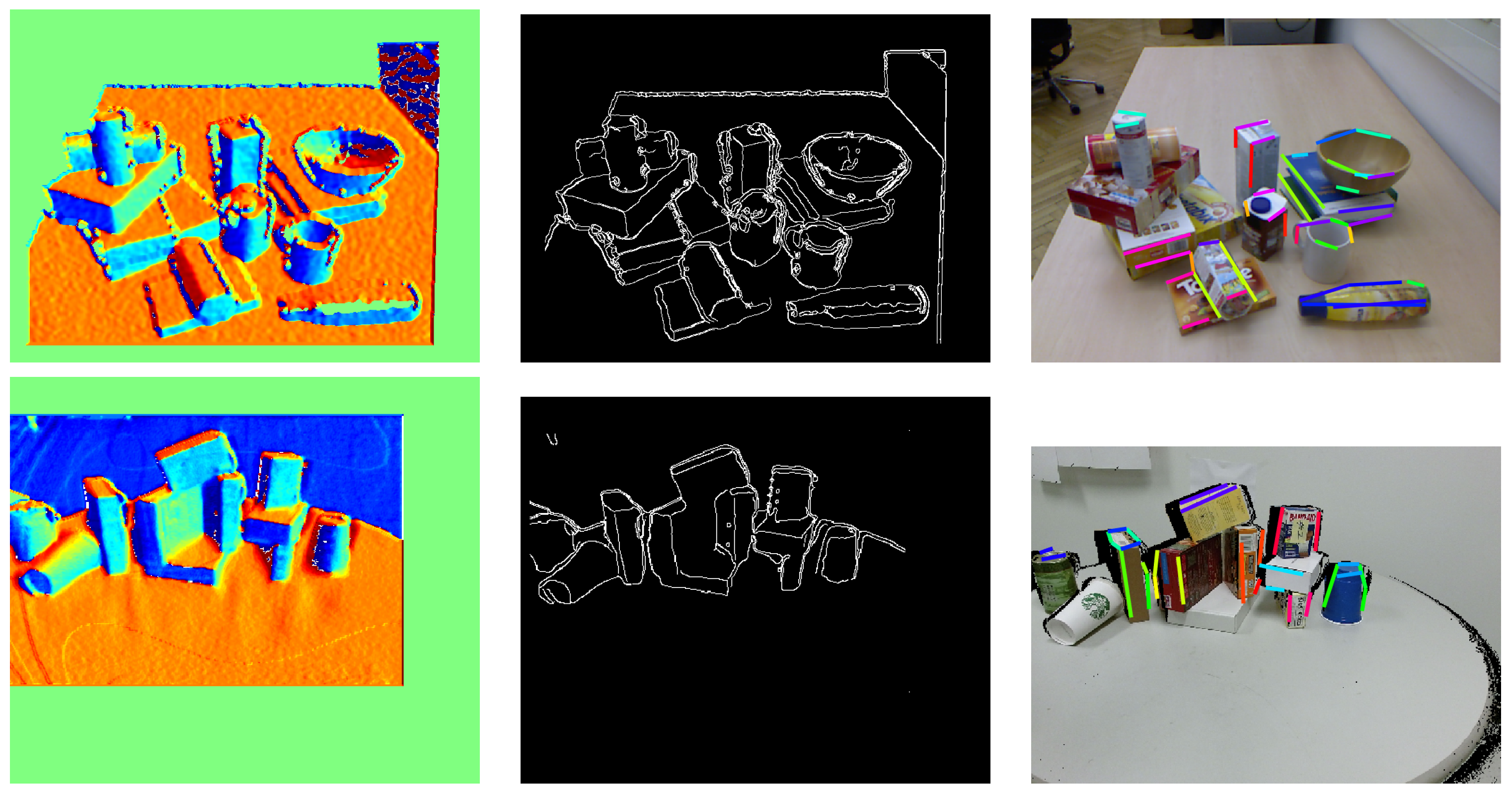
While the first-generation UCF-MANUS relied on a library of objects with known grasping setpoints, the proposed work allows for generating grasping setpoints by utilizing a novel object 6D pose estimation algorithm, which is based on partial information captured from a single view using a 3D (depth sensing) camera [8,9]. Specifically, contact regions are determined based on edge geometric features derived from analysis of the depth map data. The framework is based on the supporting principle that potential contacting regions for a stable grasp can be found by searching for (i) sharp discontinuities and (ii) regions of locally maximal principal curvature in the environmental depth map proximal to the robotic gripper and within the reachable workspace of the manipulator arm. A depth image can be shown by a 2D array of values, which is described by an operator
where z denotes the depth value (distance to the camera) of a pixel positioned at coordinates in the depth image . Mathematically speaking, our principle suggests a search for regions holding high gradient property in depth or depth direction values. Gradient image, gradient magnitude image, and gradient direction image are defined as follows:
where gradient magnitude image pixels describe the change in depth values in both horizontal and vertical directions. Similarly, each pixel of the gradient direction image demonstrates the direction of the largest depth value increase. Regions showing discontinuity in intensity values in the depth and gradient direction images locally divide the area into two sides and cause the appearance of edges as shown in Figure 7.

Figure 7.
Applied edge detection on an acquired depth map. (a) RGB image of the scene, (b) Color map of the raw depth map. White pixels imply non-returned values from the sensor (depth shadows) (c) Color map of the processed depth map, (d) Color map of computed gradient direction image, (e) Detected edges before applying the morphological operations (f) Detected edges after the morphological process, [8].
Since the output of this algorithm is a set of graspable pairs (see Figure 8), further processing is needed to select a desired pair of grasping edges. To improve the user experience, a feature score-based automated pair selection algorithm is employed in the second-generation UCF-MANUS. Specifically, a vector was defined to store the following set of features for each edge pair

Figure 8.
Outcome of the grasp planning algorithm for a complex scene. (Left): Color map of the direction of Gradient, (Middle): Binary image of detected depth edges, and (Right): Detected grasp candidates for a parallel gripper [8].
Here, is the error of the RANSAC algorithm which represents the quality of the fitted plane, and denote the lengths of each edge, and denote the pixel number of each edge, represents the angle between the surface normal and z-axis of the robot base frame, while denotes the angle of the surface normal and x-axis of the base frame. In order to make all the scores comparable across different feature pairs, we defined the normalized feature vector for each edge pair as follows:
where , , and denote the maximum value of those features among all the edge pair candidates. Finally, the highest score is picked as the target graspable edge pair, and the estimated 6D position is communicated to the robot control module as discussed below.
3.3. Motion Control for Object Approaching
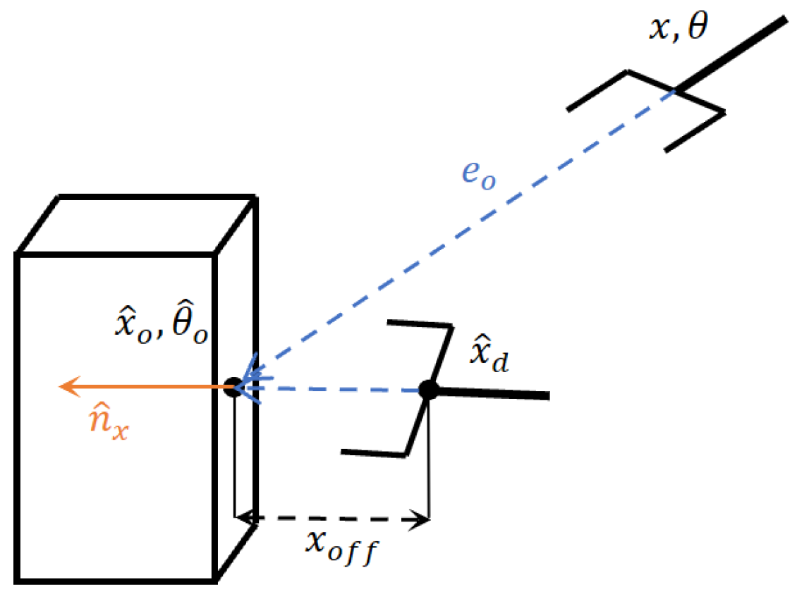
In this control mode, the system automatically generates the motion control for the end-effector to approach the detected object. As shown in Figure 9, the translation axis controller drives the end-effector to the desired approaching position denoted by , while the rotational axis controller keeps the end-effector always pointed at the detected object. Specifically, once the 6-DOF estimated object position and orientation is obtained from the depth image-based autonomous grasping algorithm as discussed above in Section 3.2, we define a desired approaching position as where , denotes the unit surface normal vector of the estimated object surface, while denotes the distance from the object surface to the desired approaching position. For the translation motion, a position error is defined based on which the velocity control input is designed simply as a proportional feedback controller where is the preset (by user) translation velocity for the end-effector.

Figure 9.
Gripper orientation control explaining plot.
For generating rotational motion, we designed an algorithm to generate the desired angular velocities for the end-effector such that the target object always remains in the camera FOV (Field of View). Specifically, we first defined an auxiliary object-position error as based on which the desired yaw and pitch angles are designed as follows
Next, an angle error vector is defined based on which the robot angular velocity input is generated as proportional feedback controller , where is a preset (by user) angular velocity for the end-effector. Here, , , and denote, respectively, the current yaw, pitch, roll angles of the end-effector, while denotes the roll component of the estimated object orientation .
3.4. Motion Control for Robust Object Envelopment
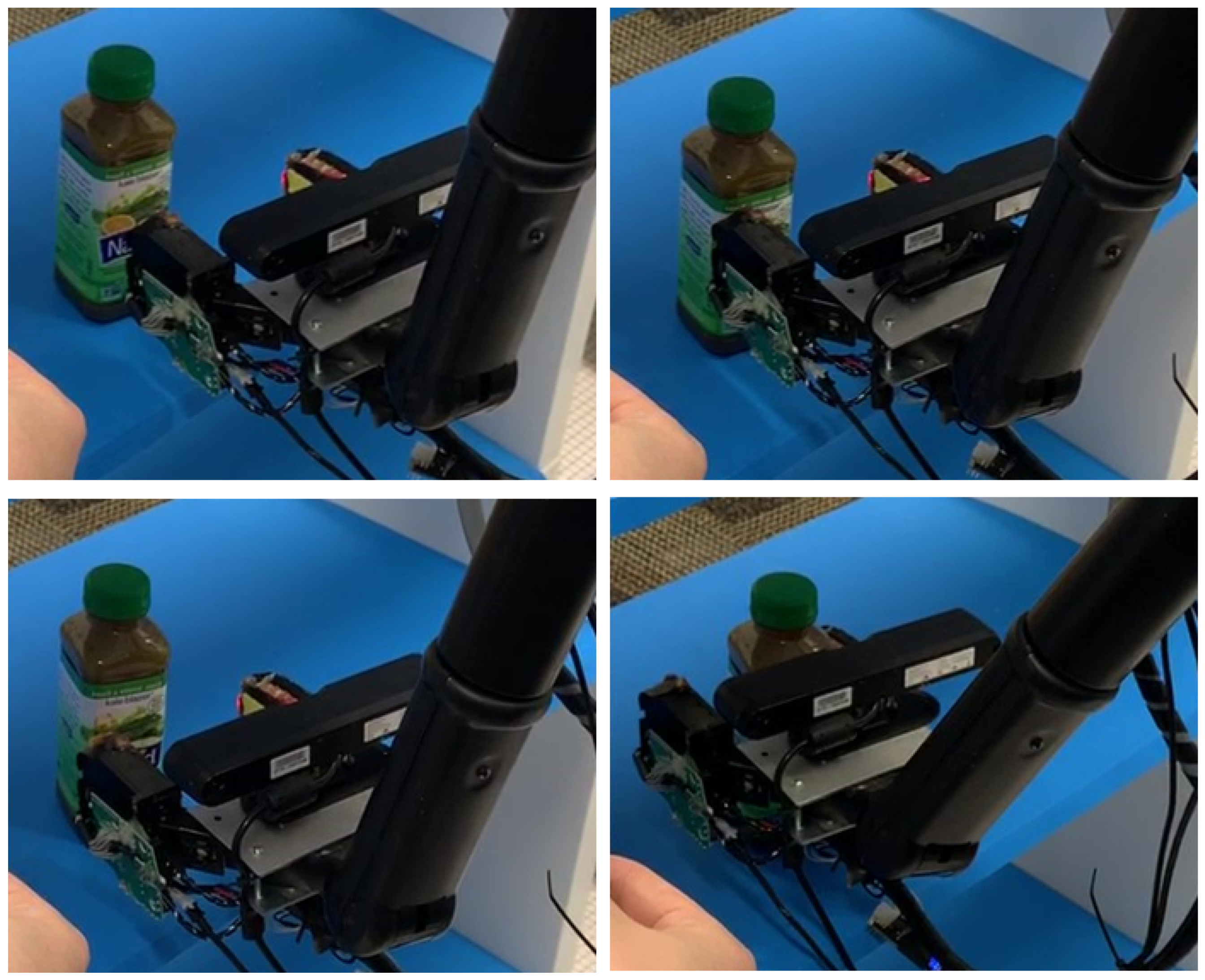
In the previous generation of the UCF-MANUS, the robust approaching algorithm only compensated for the position error along the end-effector x-axis. Specifically, optical gates inside the gripper fingers were utilized to stop the robot motion along its x-axis once the object envelopment by the gripper fingers was deemed sufficient [7]. However, such a system is not robust to deviations along other axes, which are common to assistive robots like the UCF-MANUS due to extensive gearing and transmission. Camera calibration and visual estimation errors can also contribute to this uncertainty. In the current generation, embedded tactile sensors along the surface of the gripper fingers were utilized to augment our robust approaching control that can detect collisions and adjust the end-effector trajectory during the final approach. It is critical to note that range limitations on the 3D camera do not allow for any visual/depth measurements to be made when the end-effector is in close proximity to the target. This motivates us to augment the 3D-vision system with a haptic-based system to implement a time-efficient solution to approaching uncertainties.
Specifically, the algorithm works as follows. If the estimation error causes the open-loop approaching process along the x-axis to fail (for example, resulting in a collision causing the gripper to push the object), the end-effector retreats to an adjusted pre-approaching position and re-approaches with a correction accounting for position error along the end-effector y-axis. Using an object-position estimate obtained from an eye-in-hand camera system, the system drives the end-effector to reach the pre-approaching position; the end-effector velocity control only commands the end-effector x-axis velocity to approach the object until the gripper senses the object is in the gripper. However, due to the kinematic uncertainty emerging from the robot’s extensive gearing and transmission, the estimated object position could have a deviation from the actual position. As a result of such estimation error, the open-loop approaching process could fail, for example, pushing the object. To tackle this challenge, this algorithm generates the adjusted pre-approaching position based on the tactile sensor feedback. Starting from the initial approaching position , an adjustment vector, , is created for the gripper to retreat, pursuant to every collision. Here, is a preset adjustment length, while is an indicator vector comprising of and 0 entries depending on which finger (left/right) or which surface (top/bottom/front) is involved in the collision. While the approaching velocity command is designed as , the retreating motion controller is designed as . Results from this robust envelopment approach are illustrated in Figure 10.

Figure 10.
Video frames of robust envelopment. (Top left) shows the estimated pre-approaching gripper position. (Top right) shows the collision between the gripper and the target object. (Bottom left) shows adjusted pre-approaching position. (Bottom right) shows the final position to execute a successful grasp.
4. HRI Framework and Adaptive UI Design
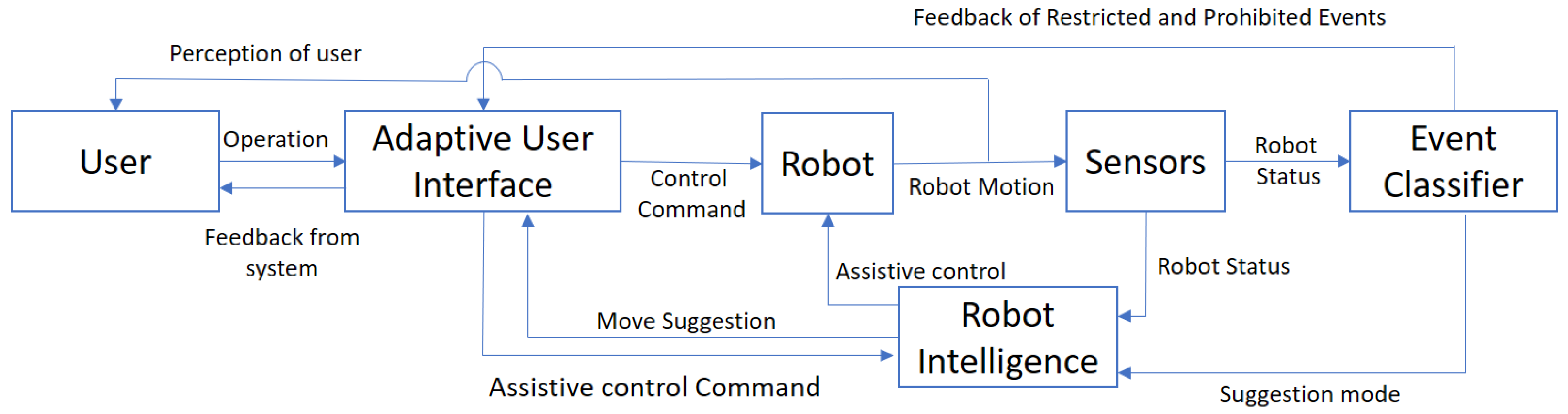
Since potential users include a broad set of people with disabilities, the users are likely to need different modes and levels of assistance. As shown in Figure 11, the user can control the robot via either manual control commands or assistive control commands. While assistive control allows the robot’s intelligent software agent to take over all or part of the control, the user still has overall supervisory control to command the robot. Furthermore, all system events are classified as one of three different levels: (A) Suggested, (B) Restricted, and (C) Prohibited. At Level A, the system will make suggestions for hand or arm movements to effectively reach the desired target in the environment. At Level B, restricted events include some constraints on robot motion, such as ‘Food may spill if gripper rolls further’ or sensing of imminent collisions. Here, the robot offers a warning to the user or even soft resistance to a commanded motion if it recognizes it as deleterious, but the user is allowed to override such warnings. As for prohibited events at Level C, the robot offers hard resistance (with user feedback) when it detects the physical motion limits of the robot or environment collisions.
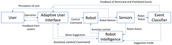
Figure 11.
Human–robot interaction framework.
4.1. User Interface Overview
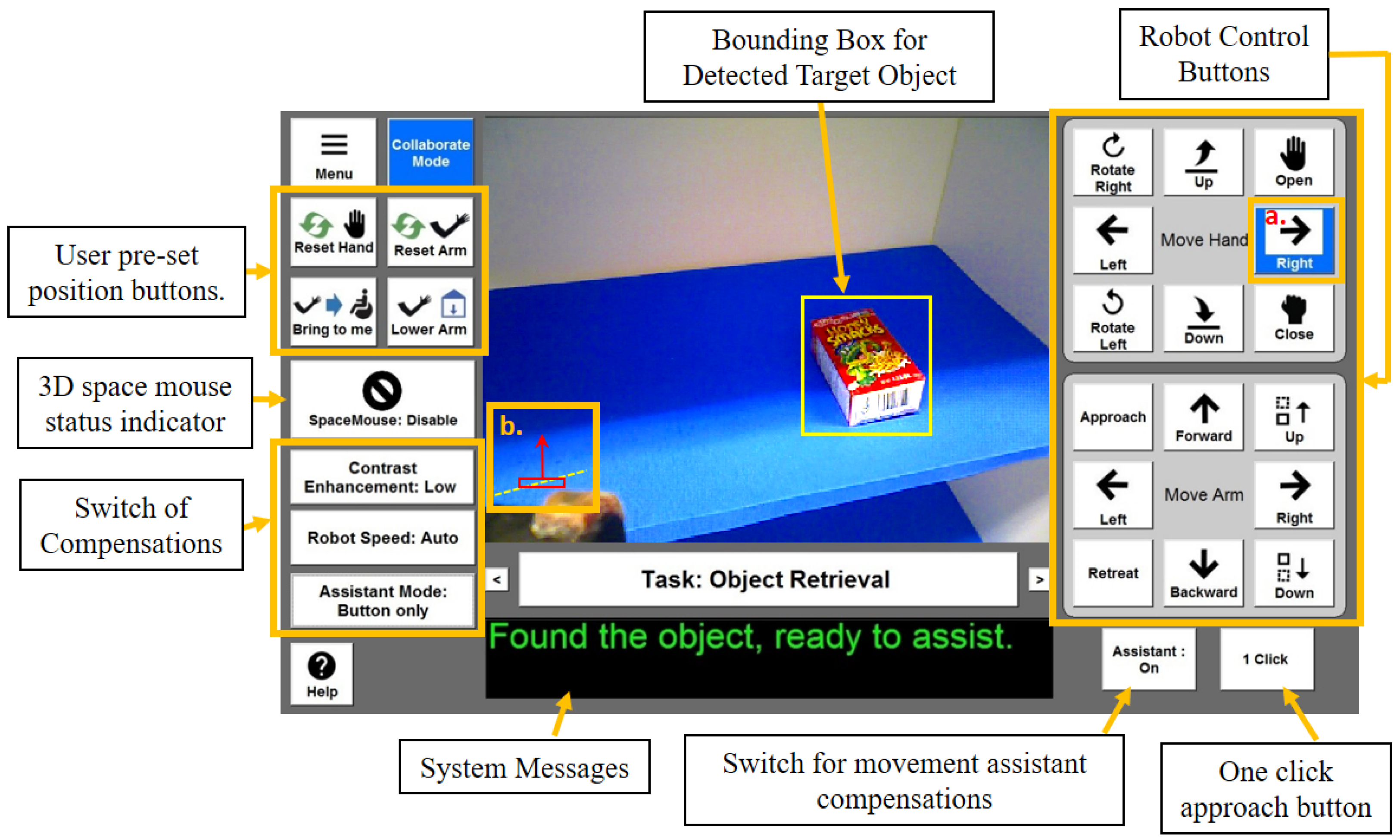
To adapt to different users and provide useful compensations for them, a group of the most significant human factors essential to teleoperating a robot was selected, and compensations were built for those in the UI. The map between assistive function/compensation and human factors is shown in Table 1. Before the user operates the robot, we provide the user with a series of tests for different human factors. Then, the system automatically turns compensation features ON or OFF according to these test scores; however, the users are able to override these choices at any time. In the adaptive UI, controls are organized by task. The UI design is shown in Figure 12. The right side of the display has two control boxes and two functional buttons. The upper box controls all the commands related to gripper motions, such as opening/closing, rotating the wrist up/down, etc. The lower box contains all the arm translational motions, such as moving forward/backward, etc. The ‘Assistant’ button toggles the assistant system for Move Suggestions or Click to Approach compensations but also indicates assistant status. A ‘1 Click’ button is used to control the ‘Click to Approach’ movement. The middle of the interface has a viewfinder for the gripper-mounted camera. A black background box provides written feedback on the current state of the system (such as ‘Found the Object, Ready to Assist’) or a warning message (such as ‘Environment Collision’). On the left side of the interface, preset arm position buttons are provided which can allow users to quickly navigate the arm to one of many commonly needed positions. A SpaceMouse mode icon informs the user of the current mode of the SpaceMouse by both text and sign. The other three buttons allow for control of compensations for different human factors. The ‘Contrast Enhancement’ button can switch between three different enhancement levels, namely ‘OFF’, ‘LOW’, and ‘HIGH’. The ‘Robot Speed’ button can switch between four speed options, namely ‘low’, ‘medium’, ‘high’, and ‘auto’. The ‘auto’ speed mode is ‘Object Proximity Velocity Reduction’ in Section 4.3.2. The ‘Assistive mode’ button is for movement suggestions; the user can select this mode to be one of three choices: ‘off’, ‘Button only’ and ‘Button + Voice’. In the ‘Button only mode’, the system will highlight the suggested movement button as a reference for the user. In the ‘Button + Voice’ mode, the system will read out the suggested button when the button is just highlighted.

Table 1.
Compensation map with evaluation for deficiencies. (WM: Working Memory; RI: Response Inhibition; PS: Processing Speed; DP: Depth Perception; SA: Spatial Ability; CS: Contrast Sensitivity.) ‘++’ and ‘+’ stands for ‘most appropriate’ and ‘may be useful’, respectively.
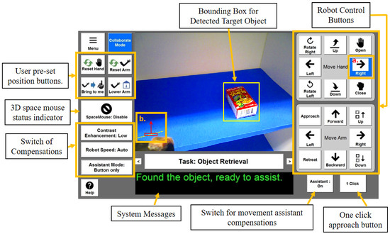
Figure 12.
UCF-MANUS Adaptive User Interface.
4.2. Movement Suggestion Mode: A Finite Machine-Based Design
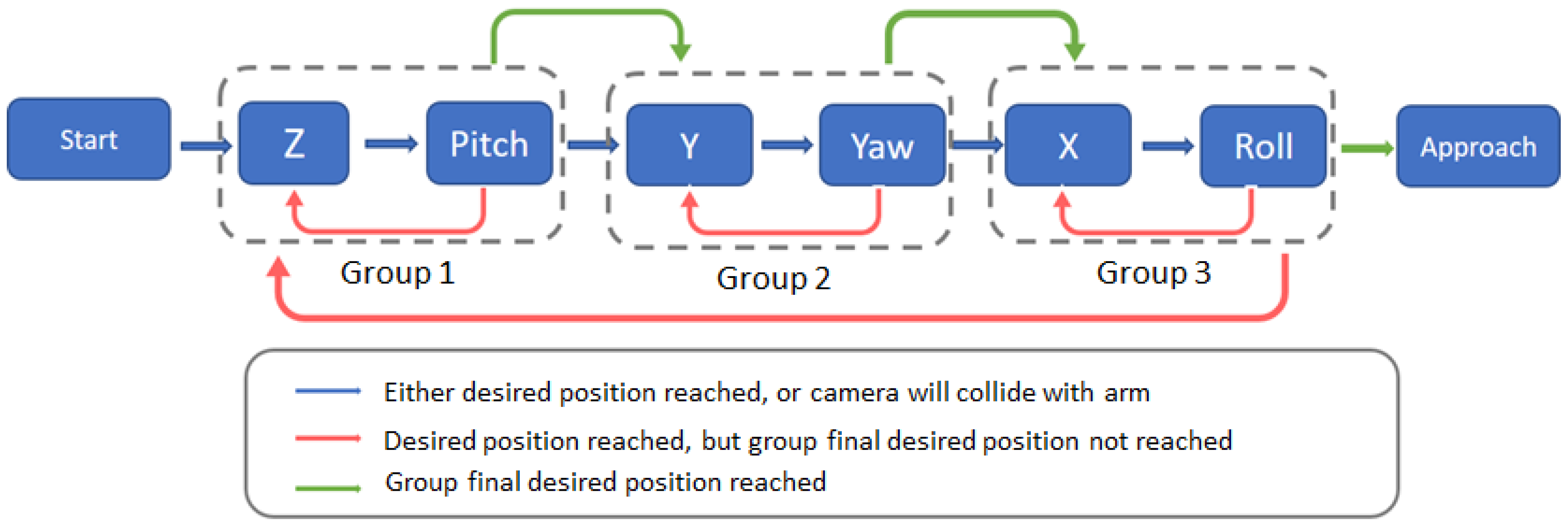
As part of sliding-scale autonomy, besides the fully manual and fully autonomous approaching control, the user is provided with a movement suggestion mode. Under this suggestion mode, the user can operate the robot manually, while the assistive robot system proffers possible movement suggestions for the user in case they are having trouble reaching the object. Specifically, in the suggestion mode, we define a configuration error , where is the current configuration of the end-effector. Since the user can only control one axis each time, the minimum (in general) number of operations for the end-effector to reach the desired pre-approaching position is six. Even though the final configuration required for the robot is the desired configuration, it is possible that the object, during the movement operation, may move out of the camera field of view (FOV) due to a particular sequence of movements in a certain axis or group of axes. To keep the object always in view, we design a finite-state machine to generate the suggested movements. As shown in Figure 13, each block represents one movement suggestion. We sort the motion in the six axes into three different groups. The condition for switching to the next group/state is when the group/temporary desired position is reached. The only exception for the state changes is the collision warning. If the desired position leads the robot arm to collide with the camera, the system will change to the next state to avoid this potential collision. To make sure that the final position is reached in all axes after the third group’s desired position is reached, the system will check whether all the final desired positions have been reached or not. If not, the suggestion will switch to the first state. Otherwise, a failure state is generated to notify the user to manually approach the object.

Figure 13.
Move suggestion finite-state machine. Each block represents a move suggestion; arrows indicate state transition.
To generate the desired position when the system switches states, a temporary desired position will be calculated. Since we have the estimated position of the target object, we can use the camera model and camera position to calculate the pixel position of the object in the camera view. Before suggesting the motion, the algorithm will first calculate the object pixel position of the temporary waypoint
where is an indicator vector for the suggested axis such that in N, the value of the suggested axis will be 1, and the rest are set to 0. Here, is the position error at the beginning of the iteration of the suggestion. Then, we can have the object pixel position as follows:
where are intrinsic parameters of the camera. Based on the predicted object pixel position, it can be determined if the object will continue to remain in the camera FOV or not. If the temporary desired position is projected to lose the object from the camera FOV, an updated temporary desired position is obtained as
where is a coefficient to update the temporary desired position. Next, the system compares the object pixel position with the temporary desired position. Then, if appropriate, the temporary desired position is assigned to the final desired position.
4.3. Design of Compensations
4.3.1. Contrast Enhancement
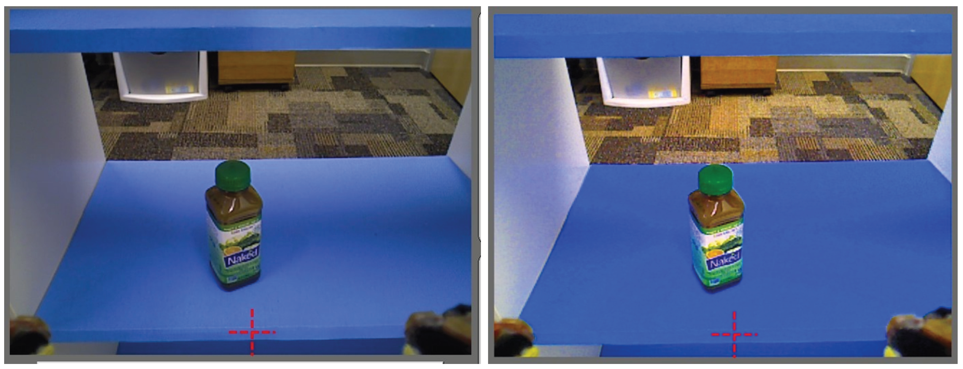
Users with visual contrast sensitivity deficiency may have difficulty perceiving objects seen in the camera view. It could also affect the depth estimation of the user. To compensate for the visual contrast sensitivity deficiency, we convert the view from RGB color space to HSV color space to change the saturation and brightness of the picture, including the background and the foreground, which in turn enhances the contrast of the view. As such, this compensation artificially amplifies the contrast of a scene in the UI view. Furthermore, the user has the ‘low’ and ‘high’ options for the level of enhancement. Figure 14 shows the view without contrast enhancement and the enhanced view.
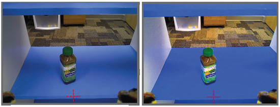
Figure 14.
Camera view contrast enhancement. (Left) figure is the normal view from the camera, (right) figure is the contrast-enhanced view.
4.3.2. Object Proximity Velocity Reduction
Difficulty in motor control, as well as decreased processing speed, can lead to difficulties making fine movements required near objects. To account for this, the arm movement is segmented into operations requiring fine motion (close to objects) and gross motions (far from objects). The arm will operate at a slower speed when it detects that it is near an object, thus allowing for greater decision and reaction time for the user. Distance from the gripper to the object is obtained from the RGBD camera. This velocity reduction can also be selected manually; specifically, it has three speed options, namely, ‘slow’, ‘medium’, and ‘high’.
4.3.3. Orientation Indication
Users with deficient spatial orientation or visualization ability may have difficulty determining the position of the arm or gripper, including its relationship to the object they wish to manipulate. This may be magnified by the user’s limited dexterity and difficulty with controls. In settings with limited visual references, it may be difficult to determine the orientation of the gripper. The orientation indicator provides an artificial horizon, as well as a gripper position indicator.
5. Results
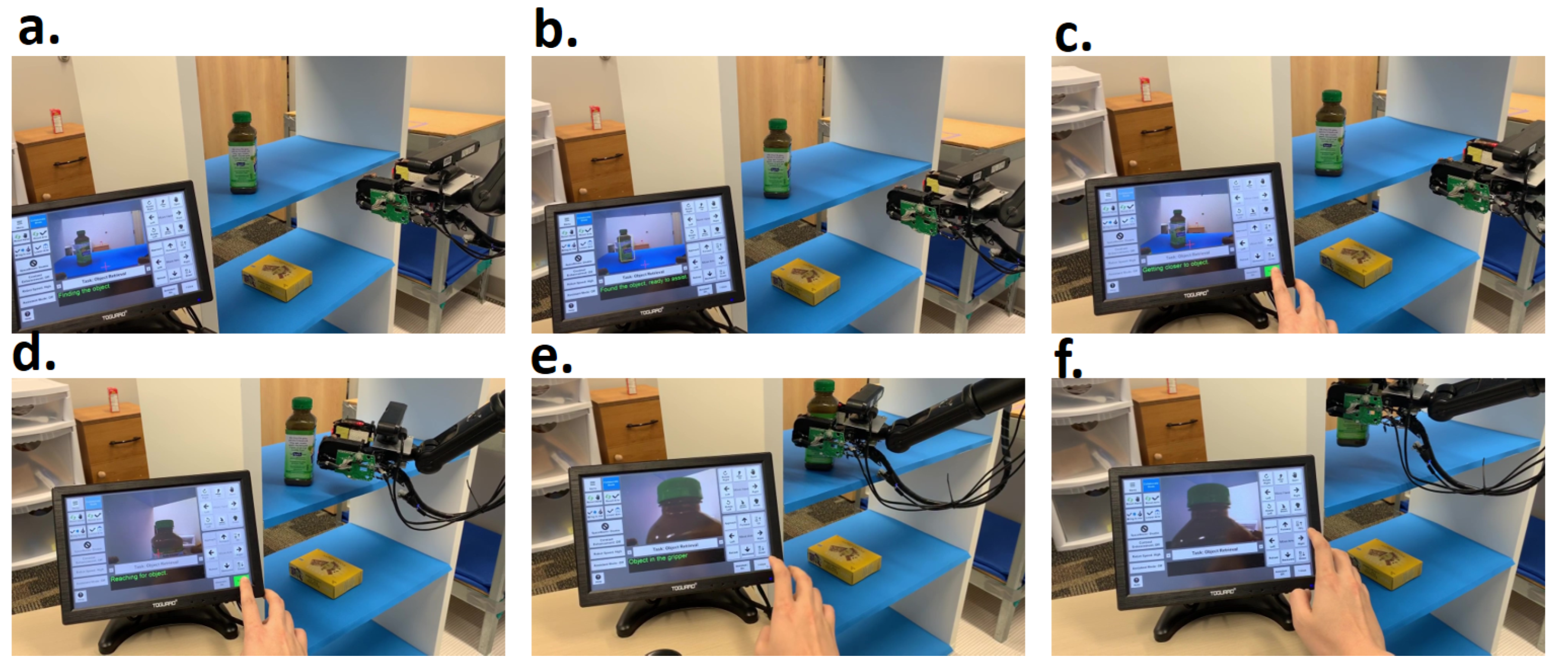
To test the effectiveness of these assistive modes, we tested them with pick-and-place tasks five times under each mode. The manual mode data are collected with an able-bodied and experienced user, so the manual mode data could be used as a benchmark for the upper limit of performance for any user (whether with or without a disability). The comparison for all three modes of the end-to-end task is shown in Table 2. The end-to-end operation under one-click mode and move suggestion mode is shown in Figure 15 and Figure 16. It can be seen that the ‘move suggestion mode’ and ‘one-click mode’ both need extra time to detect the object. However, for the manual mode, we cannot simply separate the observation time during operation. So, we compare the ‘object detection’ and ‘Reaching the object’ phases together, i.e., through the addition of columns 2 and 3. The manual mode averages 24.2 s. The one-click mode averages 30s, but the move suggestion mode averages 57 s. The move suggestion mode costs more time, but only because of a programmed delay of 2.5 s before the move suggestion comes on; if needed, this delay can be turned off. The one-click mode costs slightly more time than the manual mode, but the number of commands is reduced from 10 to 4. The suggestion mode costs more time due to the programmed delay, but the average total commands are similar to the manual mode. After reaching the object, the ‘grasp and lift’ basically costs the same time and the same number of operations. For the overall performance, the one-click mode used the minimum number of commands and slightly more time than the manual mode, and the user has supervisory (single-switch active latch) control of the robot during the whole process. The move suggestion mode costs more time than the manual mode, but it can keep the total commands at the same level as the manual mode. It can still reduce the control complexity for users who lack experience or have deficits in working memory or spatial ability.
Table 2.
Assistive mode comparison.
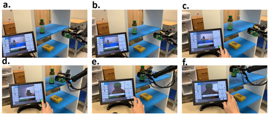
Figure 15.
Video frames of the autonomous grasping. (a) Beginning of the process, the system is locating the object. (b) The system found the object. (c) User using the ’Click to Approach’ button to activate autonomous motion. Gripper is reaching the object automatically. (d) Gripper reaches pre-approaching position, starts to approach object. (e) When object is enveloped by gripper, algorithm will stop approaching motion, and ask user to initiate gripper closure. (f) User closes gripper and picks the object.
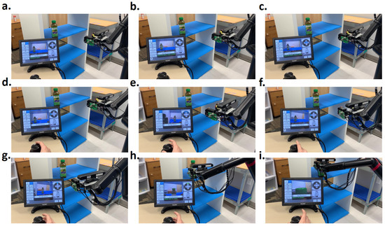
Figure 16.
Video frames of the move suggestion mode. (a) Object detection start. (b) Object detected. (c) Suggest move up. (d) Suggest move left. (e) Suggest pan right (break down the left motion to prevent loss of object from camera view), (f) Suggest move left again. (g) Suggest move forward. (h) Reach the object, user starts approaching the object. (i) Grasp and lift the object.
6. Discussion
It is well known that excessive dependence on tactile sensors can introduce additional complexity. These sensors require accurate calibration procedures in general. However, in the UCF-MANUS, the FSR measurements are utilized inside an adaptive control algorithm that finds the system equilibrium and the required force based on the system dynamics. Thus, if it is out of calibration, it will report inaccurate force readings but the applied force is still the minimal force that is required to immobilize the target object. An additional cause of system errors is due to camera internal and external calibration errors. While the RGBD camera-in-hand used in UCF-MANUS does benefit from standard calibration procedures, there is nevertheless a residual error in locating the robot end-effector. This is taken care of through Robust Object Envelopment motion control algorithm described above that compensates for residual errors along all three axes of the end-effector. Overall, all sensors utilized in the foregoing development are calibrated at the time of incorporation into the system and periodically; however, the system hardware and algorithms are designed to make the overall system robust to residual sensor calibration errors.
7. Conclusions
The UCF-MANUS system is a generic pick-and-place assistive robot that can be harnessed for completing various ADL tasks useful to individuals with disabilities. It can be compared and contrasted with several commercial assistive robots, most of which are specialized for particular tasks [48]. For example, the feeding robot Obi can feed an individual in nearly any position and can be multimodally controlled by any part of the body that can activate a switch. Another example is the Lean Empowering Assistant (LEA) robot, which is a walker capable of autonomous navigation. It can react intelligently to various environmental conditions. Panasonic has demonstrated a robotic hair-washing assistant that can apply shampoo and hot water and gently massage the user’s scalp. The meal-assistance solution HAL proposed in [49], the haptics- and vision-based intelligent bite acquisition and bite transfer strategy proposed in [50] and a versatile scooping/skewering system based on the Willow Garage PR2 robot in [51] are significant advancements over earlier feeding devices (e.g., Handy [52], MySpoon [53]) in that they can be used in relatively unstructured settings due to their computer-vision-based capability to detect the location of the food and the mouth.
To conclude, we have discussed the design and implementation of the assistive controller and adaptive user interface of the UCF-MANUS 2.0 assistive system. In addition, we presented the new features that are implemented to compensate for the selected human factors, which cover dexterity, working memory, response inhibition, processing speed, depth perception, spatial ability, and contrast sensitivity. By providing a multimodal hybrid interface, UCF-MANUS 2.0 takes a big step toward the provision of universal access. The sliding autonomy interface allows users to easily and at any time switch between three modes: Manual, One-Click, and Move Suggestion. Following experimental results, we showed that the one-click mode can reduce the reaching time by ~31% and the command complexity by ~62%. Thus, the one-click mode reduces the complexity and time significantly, while the move suggestion mode makes sure that the number of user commands matches that of an able-bodied, experienced user. However, the object detection time is higher than in the manual mode, and it consumes at least 25% of the whole processing time. This can be improved by implementing the algorithm in other programming languages or on GPU-based platforms. In the future, we will run user studies with subjects with disabilities and analyze the performance for all the features while also optimizing the object detection time so as to further improve the user experience.
Author Contributions
Conceptualization, A.B.; methodology, A.B.; software, Z.D., A.J. and M.A.-M.; validation, Z.D., A.J. and M.A.-M.; formal analysis, Z.D.; investigation, Z.D., A.J. and M.A.-M.; resources, A.B.; writing—original draft preparation, Z.D.; writing—review and editing, A.B.; visualization, Z.D. and A.J.; supervision, A.B.; project administration, A.B.; funding acquisition, A.B. All authors have read and agreed to the published version of the manuscript.
Funding
This study was funded in part by NIDILRR grants 90IFST0024-01-00 and H133G120275 and in part by NSF grant numbers IIS-1409823 and IIS-1527794. However, these contents do not necessarily represent the policy of the aforementioned funding agencies, and you should not assume endorsement by the Federal Government.
Data Availability Statement
Data are contained within the article.
Acknowledgments
We want to acknowledge the efforts of Adem Robson (former M.S. student at UCF) with editing parts of the manuscript. We also want to thank the countless undergraduate students who worked in the Assistive Robotics Laboratory at UCF over the years and wrote parts of the code that form the foundations of the UCF-MANUS system.
Conflicts of Interest
The author Zhangchi Ding was employed by the company Flexiv Ltd. The remaining authors declare that the research was conducted in the absence of any commercial or financial relationships that could be construed as a potential conflict of interest.
References
- Fall, C.L.; Quevillon, F.; Blouin, M.; Latour, S.; Campeau-Lecours, A.; Gosselin, C.; Gosselin, B.A. Multimodal Adaptive Wireless Control Interface for People With Upper-Body Disabilities. IEEE Trans. Biomed. Syst. 2018, 12, 564–575. [Google Scholar] [CrossRef]
- Aronson, R.M.; Santini, T.; Kübler, T.C.; Kasneci, E.; Srinivasa, S.; Admoni, H. Eye-hand behavior in human-robot shared manipulation. In Proceedings of the HRI ’18: ACM/IEEE International Conference on Human-Robot Interaction, Chicago, IL, USA, 5–8 March 2018; Association for Computing Machinery: New York, NY, USA, 2018; pp. 4–13. [Google Scholar]
- Admoni, H.; Dragan, A.; Srinivasa, S.S.; Scassellati, B. Deliberate delays during robot-to-human handovers improve compliance with gaze communication. In Proceedings of the HRI ’14: ACM/IEEE International Conference on Human-Robot Interaction, Bielefeld, Germany, 3–6 March 2014; Association for Computing Machinery: New York, NY, USA, 2014; pp. 49–56. [Google Scholar]
- Crewe, N.M.; Krause, J.S. Spinal cord injury. In Medical, Psychosocial and Vocational Aspects of Disability; Elliott and Fitzpatrick: Athens, Greece, 2009; pp. 289–304. [Google Scholar]
- Cohen, M.L.; Tulsky, D.S.; Holdnack, J.A.; Carlozzi, N.E.; Wong, A.; Magasi, S.; Heaton, R.K.; Heinemann, A.W. Cognition among community-dwelling individuals with spinal cord injury. Rehabil. Psychol. 2017, 62, 425. [Google Scholar] [CrossRef]
- Kim, D.-J.; Wang, Z.; Behal, A. Motion Segmentation and Control Design for UCF-MANUS—An Intelligent Assistive Robotic Manipulator. IEEE/ASME Trans. Mechatron. 2012, 17, 936–948. [Google Scholar] [CrossRef]
- Kim, D.-J.; Wang, Z.; Paperno, N.; Behal, A. System Design and Implementation of UCF- MANUS—An Intelligent Assistive Robotic Manipulator. IEEE/ASME Trans. Mechatron. 2014, 19, 225–237. [Google Scholar] [CrossRef]
- Jabalameli, A.; Behal, A. From Single 2D Depth Image to Gripper 6D Pose Estimation: A Fast and Robust Algorithm for Grabbing Objects in Cluttered Scenes. Robotics 2019, 8, 63. [Google Scholar] [CrossRef]
- Roberts, Y.; Jabalameli, A.; Behal, A. Faster than Real-time Surface Pose Estimation with Application to Autonomous Robotic Grasping. MDPI Robot. 2022, 11, 7. [Google Scholar] [CrossRef]
- Wang, Z.; Kim, D.-J.; Behal, A. Design of Stable Visual Servoing under Sensor and Actuator Constraints via a Lyapunov-based Approach. IEEE Trans. Control. Technol. 2012, 20, 1575–1582. [Google Scholar] [CrossRef]
- Kim, D.-J.; Lovelett, R.; Behal, A. An Empirical Study with Simulated ADL Tasks using a Vision-Guided Assistive Robot Arm. In Proceedings of the 2009 IEEE 11th International Conference on Rehabilitation Robotics, Kyoto, Japan, 23–26 June 2009; pp. 504–509. [Google Scholar]
- Tsui, K.; Yanco, H.; Kontak, D.; Beliveau, L. Development and Evaluation of a Flexible Interface for a Wheelchair Mounted Robotic Arm. In Proceedings of the 2008 3rd ACM/IEEE International Conference on Human-Robot Interaction (HRI), Amsterdam, The Netherlands, 12–15 March 2008; pp. 105–112. [Google Scholar]
- Vu, D.; Allard, U.C.; Gosselin, C.; Routhier, F.; Gosselin, B.; Campeau-Lecours, A. Intuitive Adaptive Orientation Control of Assistive Robots for People Living with Upper Limb Disabilities. In Proceedings of the 2017 International Conference on Rehabilitation Robotics (ICORR), London, UK, 17–20 July 2017; pp. 795–800. [Google Scholar]
- Herlant, L.V.; Holladay, R.M.; Srinivasa, S.S. Assistive teleoperation of robot arms via automatic time-optimal mode switching. In Proceedings of the 2016 11th ACM/IEEE International Conference on Human-Robot Interaction (HRI), Christchurch, New Zealand, 7–10 March 2016; pp. 35–42. [Google Scholar]
- Brose, S.W.; Weber, D.J.; Salatin, B.A.; Grindle, G.G.; Wang, H.; Cooper, R.A. Assistive robotics: Adaptive and intelligent robotic systems for assisting people with disabilities. IEEE Robot. Autom. Mag. 2010, 17, 30–41. [Google Scholar]
- Dario, P.; Guglielmelli, E.; Laschi, C. Humanoids and personal robots: Design and experiments. J. Robot. Syst. 2001, 18, 673–690. [Google Scholar] [CrossRef]
- Tadokoro, S. Disaster Robotics; Springer: Berlin/Heidelberg, Germany, 2019. [Google Scholar]
- Cakmak, M.; Leitao, M. Human-Robot Interaction: An Introduction; CRC Press: Boca Raton, FL, USA, 2020. [Google Scholar]
- Sabanovic, S. Social Robots: Technological, Societal, and Ethical Aspects of Human-Robot Interaction; Oxford University Press: Oxford, UK, 2020. [Google Scholar]
- Krichmar, J.L.; Wagatsuma, H. Neuromorphic and Brain-Based Robots; Cambridge University Press: Cambridge, UK, 2011. [Google Scholar]
- Pineau, J.; Montemerlo, M.; Pollack, M.E.; Roy, N.; Thrun, S. Towards robotic assistants in nursing homes: Challenges and results. Robot. Auton. Syst. 2003, 42, 271–281. [Google Scholar] [CrossRef]
- Graf, B.; Hans, M.; Schraft, R.D. Care-O-bot II—Development of a next-generation robotic home assistant. Auton. Robot. 2004, 16, 193–205. [Google Scholar]
- Hussein, A.; Taha, A.; Khalid, M.H.; Omar, H. Assistive robotics: A review of applications and challenges. IEEE Access 2021, 9, 102509–102533. [Google Scholar]
- Feil-Seifer, D.; Matarić, M.J. Defining socially assistive robotics. In Proceedings of the 9th International Conference on Rehabilitation Robotics, Chicago, IL, USA, 28 June–1 July 2005; pp. 465–468. [Google Scholar]
- Tapus, A.; Ţăpuş, C.; Matarić, M.J. User—robot personality matching and assistive robot behavior adaptation for post-stroke rehabilitation therapy. Intell. Serv. Robot. 2009, 2, 169–183. [Google Scholar]
- Fasola, J.; Matarić, M.J. Socially assistive robot exercise coach: Motivating older adults to engage in physical exercise. Auton. Robot. 2012, 33, 109–127. [Google Scholar]
- Broekens, J.; Heerink, M.; Rosendal, H. Assistive social robots in elderly care: A review. Gerontechnology 2009, 8, 94–103. [Google Scholar] [CrossRef]
- Kachouie, R.; Sedighadeli, S.; Khosla, R.; Chu, M.T. Socially assistive robots in elderly care: A mixed-method systematic literature review. Int. J. Hum.-Comput. Interact. 2014, 30, 369–393. [Google Scholar]
- Wada, K.; Shibata, T.; Saito, T.; Tanie, K. Effects of robot-assisted activity for elderly people and nurses at a day service center. Proc. IEEE 2004, 92, 1780–1788. [Google Scholar]
- Broadbent, E.; Stafford, R.; MacDonald, B. Acceptance of healthcare robots for the older population: Review and future directions. Int. J. Soc. Robot. 2009, 1, 319–330. [Google Scholar] [CrossRef]
- Krebs, H.I.; Volpe, B.T.; Aisen, M.L.; Hogan, N. Increasing productivity and quality of care: Robot-aided neuro-rehabilitation. J. Rehabil. Res. Dev. 2000, 37, 639–652. [Google Scholar]
- Lo, A.C.; Richards, P.D.; Haselkorn, L.G.; Wittenberg, J.K.; Federman, G.F.; Ringer, D.G.; Wagner, R.J.; Krebs, T.H.; Volpe, H.I.; T, B.; et al. Robot-assisted therapy for long-term upper-limb impairment after stroke. N. Engl. J. Med. 2010, 362, 1772–1783. [Google Scholar] [CrossRef]
- Mehrholz, J.; Hädrich, A.; Platz, T.; Kugler, J.; Pohl, M. Electromechanical and robot-assisted arm training for improving activities of daily living, arm function, and arm muscle strength after stroke. Cochrane Database Syst. Rev. 2012, CD006876. [Google Scholar] [CrossRef]
- Dautenhahn, K. Socially intelligent robots: Dimensions of human–robot interaction. Philos. Trans. R. Soc. B 2007, 362, 679–704. [Google Scholar]
- Goodrich, M.A.; Schultz, A.C. Human-robot interaction: A survey. Found. Trends Hum.-Comput. Interact. 2007, 1, 203–275. [Google Scholar] [CrossRef]
- Tsui, K.M.; Desai, M.; Yanco, H.A.; Uhlik, C. Exploring use cases for robot-assisted wheelchair users. In Proceedings of the 6th ACM/IEEE International Conference Human-Robot Interaction, Lausanne, Switzerland, 6–9 March 2011; pp. 11–18. [Google Scholar]
- Esposito, R.; Conti, D.; Di Nuovo, A. Cognitive robotics to support child development: A review of current research. IEEE Trans. Cogn. Dev. Syst. 2021, 14, 36–50. [Google Scholar]
- Riek, L.D. Healthcare robotics. Commun. ACM 2017, 60, 68–78. [Google Scholar]
- Papadopoulos, I.; Koulouglioti, C.; Ali, S.; Lazzarino, R. Smart homes, artificial intelligence, and health: A review of literature. Front. Public Health 2020, 8, 138. [Google Scholar]
- Bevilacqua, R.; Felici, E.; Marcellini, F.; Cavallo, F. Social robots and older adults: A systematic review of cost-effectiveness studies. Aging Clin. Exp. Res. 2020, 32, 2413–2426. [Google Scholar]
- Mordoch, E.; Osterreicher, A.; Guse, L.; Roger, K.; Thompson, G. Use of social commitment robots in the care of elderly people with dementia: A literature review. Maturitas 2013, 74, 14–20. [Google Scholar]
- Sanders, M.; McCormick, E. Human Factors in Engineering and Design; McGraw-Hill International Editions; McGraw-Hill: Sydney, Australia, 1993. [Google Scholar]
- Stanger, C.A.; Anglin, C.; Harwin, W.S.; Romilly, D.P. Devices for Assisting Manipulation: A Summary of User Task Priorities. IEEE Trans. Rehab. Eng. 1994, 2, 256–265. [Google Scholar] [CrossRef]
- Ding, Z.; Paperno, N.; Prakash, K.; Behal, A. An Adaptive Control-Based Approach for 1-Click Gripping of Novel Objects Using a Robotic Manipulator. IEEE Tran. Control Syst. Tech. 2019, 27, 1805–1812. [Google Scholar]
- Patre, P.M.; MacKunis, W.; Makkar, C.; Dixon, W.E. Asymptotic Tracking for Uncertain Dynamic Systems via a Multilayer NN Feedforward and RISE Feedback Control Structure. IEEE Trans. Control. Syst. Technol. 2008, 16, 373–379. [Google Scholar] [CrossRef]
- Slotine, J.J.E.; Li, W. Applied Nonlinear Control; Prentice Hall, Inc.: Englewood Cliffs, NJ, USA, 1991. [Google Scholar]
- Available online: http://ece.ucf.edu/~abehal/AssistiveRobotics/videos/Grasping_demo.mp4 (accessed on 19 March 2025).
- Krishnaswamy, K.; Srinivas, M.; Oates, T. Survey data analysis for repositioning, transferring, and personal care robots. In Proceedings of the PETRA ’17: International Conference on Pervasive Technologies Related to Assistive Environments, Rhodes, Greece, 21–23 June 2017; ACM: New York, NY, USA, 2017. [Google Scholar]
- Kawamoto, H.; Shiraki, T.; Otsuka, T.; Sankai, Y. Meal-assistance by robot suit HAL using detection of food position with camera. In Proceedings of the 2011 IEEE International Conference on Robotics and Biomimetics (ROBIO), Karon Beach, Thailand, 7–11 December 2011. [Google Scholar]
- Gallenberger, D.; Bhattacharjee, T.; Kim, Y.; Srinivasa, S.S. Transfer Depends on Acquisition: Analyzing Manipulation Strategies for Robotic Feeding. In Proceedings of the 14th ACM/IEEE International Conference on Human-Robot Interaction (HRI), Daegu, Republic of Korea, 11–14 March 2019; pp. 267–276. [Google Scholar]
- Park, D.; Hoshi, Y.; Mahajan, H.P.; Kim, H.K.; Erickson, Z.; Rogers, W.A.; Kemp, C.C. Active robot-assisted feeding with a general-purpose mobile manipulator: Design, evaluation, and lessons learned. Robot. Auton. Syst. 2019, 124, 103344. [Google Scholar] [CrossRef]
- Topping, M.J.; Smith, J.K. The development of handy 1. A robotic system to assist the severely disabled. Technol. Disabil. 1999, 10, 95–105. [Google Scholar] [CrossRef]
- Sumio, I. Meal-assistance Robot “My Spoon”. J. Robot. Soc. Jpn. 2003, 21, 378–381. [Google Scholar]


Disclaimer/Publisher’s Note: The statements, opinions and data contained in all publications are solely those of the individual author(s) and contributor(s) and not of MDPI and/or the editor(s). MDPI and/or the editor(s) disclaim responsibility for any injury to people or property resulting from any ideas, methods, instructions or products referred to in the content. |
© 2025 by the authors. Licensee MDPI, Basel, Switzerland. This article is an open access article distributed under the terms and conditions of the Creative Commons Attribution (CC BY) license (https://creativecommons.org/licenses/by/4.0/).