1. Introduction
Universal joints are one of the most common joints used to transfer rotary motion between two shafts whose axes are inclined. There are numerous types of universal joints in the literature, but Cardan or Hook’s universal joints are widely known [
1]. However, the velocity fluctuation between the input and output shafts causes high stresses on joint parts and vibration on the output shaft [
2]. In many applications, it is required to transfer rotational motion at a constant velocity [
3,
4,
5]. To avoid this problem, it is possible to use a double Cardan joint [
6]. Furthermore, it is also possible to use constant velocity (CV) joints to overcome this problem. Theories about CV joint construction are proposed by Hunt [
7]. Constant velocity joints are couplings frequently used in industry, especially in the transportation sector and machinery. The literature offers numerous studies, patents, and designs on this topic [
8,
9,
10,
11].
The introduced joints above consist of rigid parts. Rigid mechanisms have disadvantages like wear, backlash, friction, tight manufacturing tolerances, etc. Furthermore, it is a common case for those mechanisms to operate in a wet and dirty environment, which can be very harsh for bearings [
12]. Thanks to compliant mechanisms, it is possible to design both CV or non-CV joints without rigid links and bearings [
13,
14].
Compliant mechanisms are a special type of mechanism that can transfer or transform motion, force, or energy. This type of mechanism uses flexible members instead of rigid links as in rigid mechanisms [
12,
15]. Compliant mechanisms are utilized across numerous fields and continue to be a significant area of research in mechanism studies. They can be designed on a very small scale [
16,
17], and it is also possible to see designs on a more macro scale, even in bio-inspired robotics [
18,
19]. Compliant mechanisms offer several advantages over rigid mechanisms, including lower production costs, fewer parts, improved reliability, increased precision, reduced wear, and minimal maintenance requirements. Moreover, as compliant mechanisms depend on the deflection of flexible parts, they store strain energy within their flexible members [
12].
It has been noted that the widespread application of universal joints finds its counterpart in the field of compliant mechanisms. A review of the literature reveals various designs that utilize flexible joints for motion transmission. Some of these designs are noted for their high complexity and challenging design processes [
16]. On the other hand, there are also designs that manage to maintain a simple structure with an effective design approach [
20,
21]. There are also numerous studies in the literature where compliant four-bar mechanisms are used as a base for different designs [
22,
23,
24].
In this study, a novel fully compliant four-bar-based universal joint is proposed. Two four-bar mechanisms are employed to facilitate the adjustment of the angle between the input and output shafts. Each four-bar mechanism is identical and has the same input link (crank) that connects each of the four-bar mechanisms to the other one. Furthermore, the required torque transfer from the input to output shafts is obtained by rigid and flexible segments. Comparing the compliant universal joint designs in the literature, the proposed universal joint has a simpler design. It is designed to be produced as a single piece, with relatively low cost and weight [
13,
14]. The proposed joint design is suitable for use in a variety of applications, including unmanned or robotic vehicles, robotic applications, industrial applications operating under low loads, the toy industry, and many other fields.
In the following sections, the design methodology of the mechanism is proposed first. Once the mechanism is synthesized, stress acting on the flexible hinges is investigated. The validity of the analytical results is confirmed through finite element analysis. In the final stage, an experimental setup is introduced using the proposed methodologies. For the experimental model, polypropylene (PP) is used as a manufacturing material. PP is one of the most suitable materials for compliant mechanisms [
12,
25].
2. Dimensional Synthesis
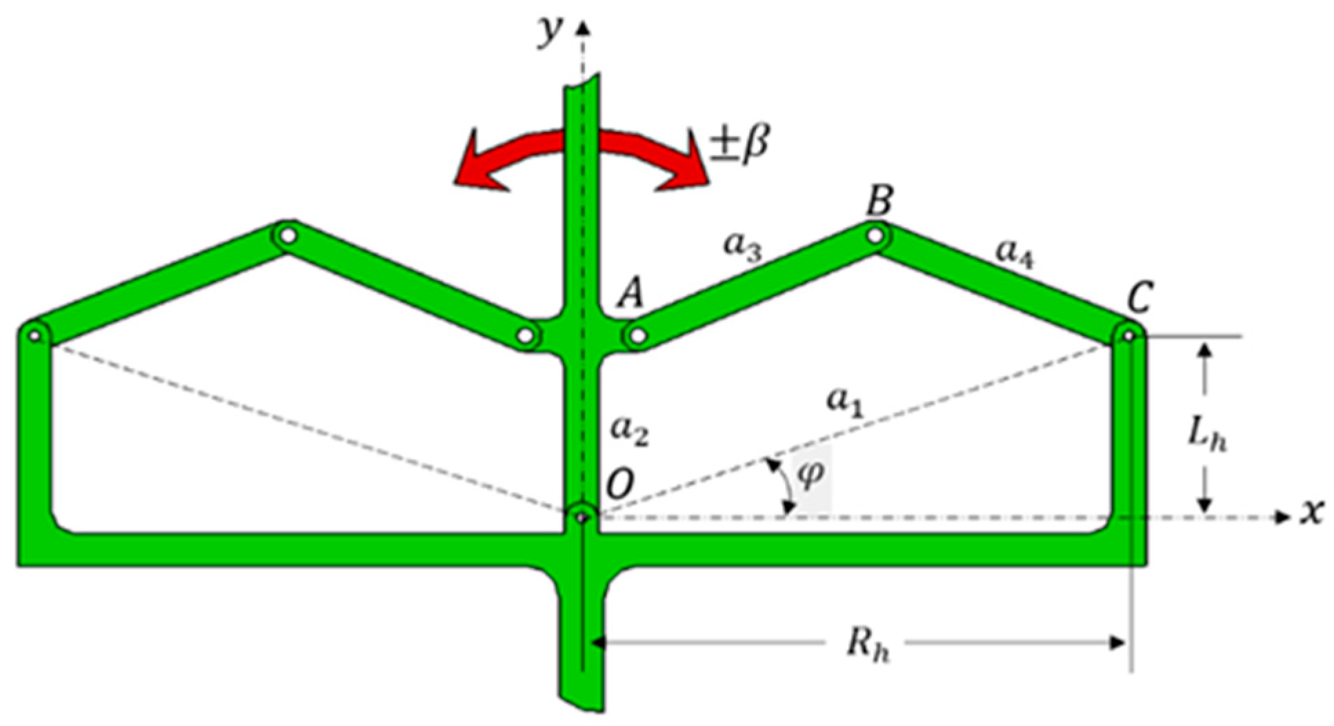
The proposed design consists of two cascade four-bar mechanisms (
Figure 1). OA, AB, BC, and CO are the links of the four-bar mechanism and mechanism and the second mechanism is its symmetrical counterpart about the y axis. The bottom side of the mechanism is the input shaft and the input link of the four-bar mechanism (OA) is the output shaft or vice versa. The position of the output shaft is adjusted by rotating the crank around point O at a rate of
β. It is important to note that
Figure 1 represents the projected view of the proposed mechanism.
A Cardan joint serves to convert rotational motion from one shaft to another. As a result, the angular position of the input link (OA) in relation to the coupler link () undergoes continuous variations on the xy and zy planes, depending on the parameter β during motion. In order to achieve spatial motion, it is necessary to replace the joint at O with a spherical joint under normal working conditions.
The mechanism illustrated in
Figure 1 has six links, seven lower pairs and no higher pairs. Employing Grubler’s formula [
26], the degree of freedom (DoF) of the mechanism is determined as 1.
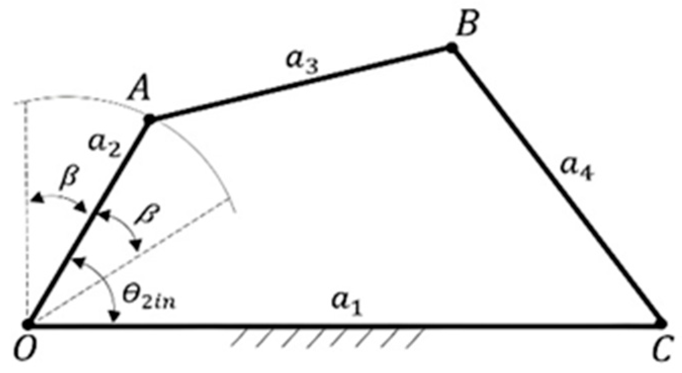
Since the four-bar mechanisms are identical about the y-axies, it is possible to synthesize the mechanism separately (
Figure 2). It should be noted that the outer dimensions (
in
Figure 1) are the design parameters of the mechanism. As a result, the length of the base link (
) is a function of the outer dimensions.
In compliant mechanisms, decreasing the angular deflection of any hinge also decrease the stress acting on the hinge caused by elastic deformation.
As a result, maintaining the angular position variations of the links relative to each other at a certain level is an important design criterion during the synthesis of the required four-bar mechanism.
There are several methods proposed for four-bar synthesis in the literature [
27,
28]. The function generation method is a useful yet simple method for synthesizing a four-bar mechanism. This method is used to determine the link lengths of the proposed mechanism. However, this method does not afford any control over the angular variation exhibited by the links in relation to each other. An iterative solution method is used to minimize the angular variations.
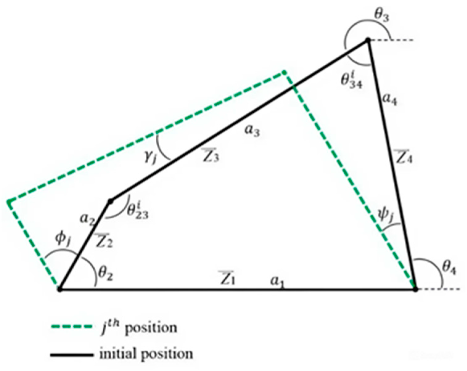
According to
Figure 3, loop closure equations of the mechanism can be expressed as follows:
Subtracting Equation (3) from Equation (4)
, is eliminated. Thus,
In Equation (5),
and
are prescribed,
are undefined, and
are the design parameters. Furthermore
is also a design parameter that defines the maximum angular variation between input and output shafts axis and j denotes the position of the mechanism. For the three precision points, Equation (5) can be arranged as a matrix.
Equation (6) is used to determine the link lengths of the rigid four-bar mechanism as a function of free parameters. However, the above equations do not guarantee the mobility of the mechanism. As a result, the link lengths of the synthesized mechanism should be checked using Grashof’s theorem [
29] for smooth motion between the minimum and maximum angular crank positions.
Equation (6) can be solved linearly by defining
and
. Once
are determined
can also be determined as a function of
. Freudenstein equation [
30] is an effective method for expressing this relation.
where
The iterative method is applied to Equation (6) for different
,
combinations. The success criterion of the iteration is to obtain minimum angular variations at the joints that connect links 2 and 3, 3 and 4, and 1 and 4 for acceptable link lengths.
where
represent the angle between link 3 and link 4 at position 1, 2 and 3, respectively.
As a result, the variation of
from position 1 to 2 (
) and position 1 to 3 (
) can be expressed as
Finally, the average of the angular change should be minimum to reduce the stress acting on the compliant hinge.
Similarly, the angular change between link 2 and link 3 can be determined.
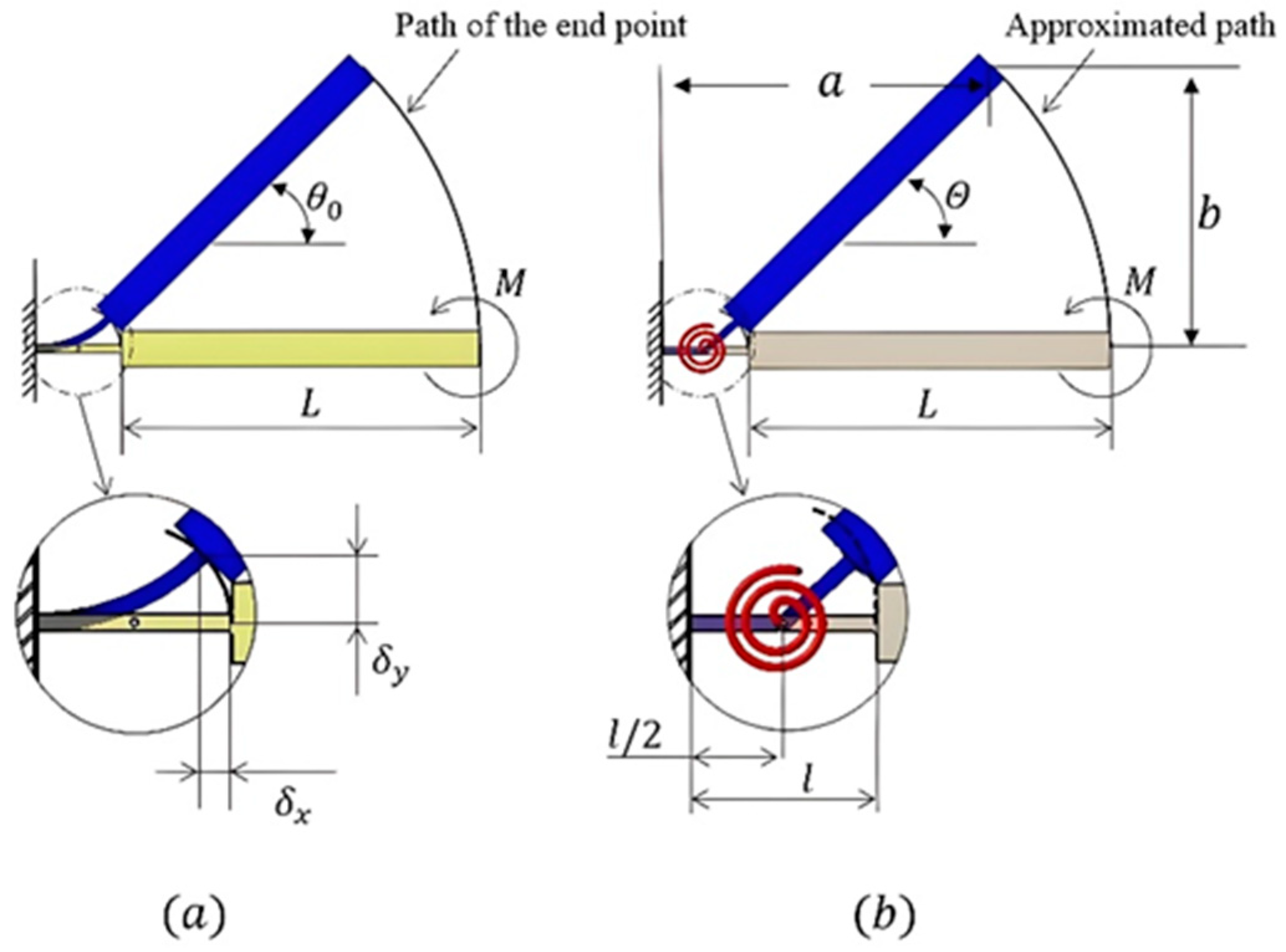
3. Pseudo Rigid Body Model (PRMB) of the Rigid Mechanism
Compliant mechanisms often experience significant deflections in their flexible segments. Therefore, when designing such mechanisms, it is crucial to employ a comprehensive analysis that considers these large deflections. However, conducting a large deflection analysis during the initial design stages of a compliant mechanism can be a complex task. Fortunately, the Pseudo Rigid-Body Model (PRBM) offers a straightforward and effective approach to analyze beams subjected to large and nonlinear deflections [
12]. The flexibility of the segments is represented by torsional springs attached to pin joints. Determining the optimal placement of these pin joints and selecting appropriate torsional spring constants are essential considerations. By applying the principles of rigid-link mechanism theory, the resulting mechanism can be thoroughly analyzed.
The fully compliant four-bar-based universal joint utilizes small-length flexural pivots. In this model, the desired motion is achieved through the deflection of the shorter, flexible segments, whereas the remaining segments exhibit a negligible amount of flexibility. This particular compliant mechanism features a characteristic pivot positioned at the center of the flexible segment.
Figure 4 illustrates the proposed rigid mechanism and its corresponding PRBM.
Initial positions of the torsional springs play an important role in reducing stress on the small-length flexural segments caused by the bend angle of the universal joint. To achieve this, the initial position of the torsional spring is determined in such a way that the small-length flexural segment deforms equally on each side at its extremum positions. Additive manufacturing is a suitable method for producing initially curved flexural segments in compliant mechanisms. Consequently, the stress exerted on the flexural segment due to deflection can be reduced by up to half of its maximum value.
where
represents the initial position.
The initial position of the input link is expressed as follows:
The fully compliant four-bar-based universal joint relies on the deflections of its flexible segments. Each hinge is responsible for compensating for the deflections of the universal joint while also withstanding the transferred torque. Additionally, increasing the number of arms, where each arm is a four-bar mechanism, linearly enhances the torque capacity of the universal joint.
The design procedure for the proposed universal joint mechanism is intended for planar mechanisms. However, when the input shaft is bent or rotates at a specific position, each arm of the universal joint undergoes spatial deflection. Thanks to the flexibility of the segments, the planar mechanism depicted in
Figure 1 can effectively operate in spatial modes through deflections.
Theoretical analysis reveals that as the number of compliant four-bar mechanisms around the shafts exceeds a certain threshold, the joint located at point O in
Figure 2 transitions into a cylindrical shape. Consequently, the revolute joint at point O effectively functions as a compliant spherical joint. Additionally, the DoF of the mechanism remains constant at 1, as indicated by Equation (1).
4. Stress Analysis of Joint
The stress acting on the small length flexural pivot is investigated in three stages. In the first stage, the stress caused by the deflection of the rigid segment is determined. It should be noted that the deflection of the hinge is the function of the universal joint bend angle.
It should also be noted that the bend angle (
) is a design parameter. As a result, the rigid body angle of the small length flexural segment at point
is defined as follows:
Similarly, the rigid body angles of the hinges at
in
Figure 4 are determined as follows:
Finally, the rigid-body angle of the hinge
in
Figure 4 is determined by using Equation (7).
For small-length flexural pivots, the pseudo rigid body angle (
) is equal to the beam end angle
[
12].
The end coordinates of the PRBM in
Figure 5 are determined approximately as a function of
.
The resistance to deflection is a function of the torsional stiffness constant (
) and the amount of torque required for the deflection (
) is proportional to the pseudo rigid-body angle (
).
Since
is much greater than
, (
), the moment acting at the end of the beam (
) is nearly equal to the torque required for the deflection of the beam (
) [
12].
Resulting maximum stress (
) occurs at the fixed end of the small-length flexural.
where
is the distance to neutral axes from the outer surface of the flexural pivot and
is the moment of inertia of the small-length flexural segment.
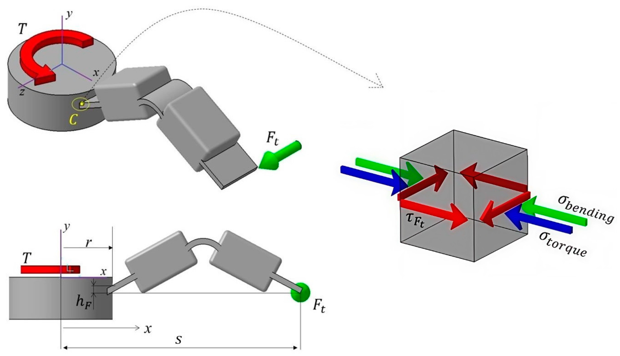
It should be noted that the stress defined by Equation (33) is for the only-bending case and will be denoted as . However, a universal joint is expected to transfer torque from one shaft to another. Consequently, in the second stage of the stress analysis, it is essential to conduct an assessment for cases involving combined loading, which includes bending, torque, and shear.
To determine the torque capacity of the proposed universal joint, a force analysis is conducted. According to
Figure 6, the transmitted torque (
) is balanced by an equivalent force couple denoted by
. It should be noted that
Figure 6 is symmetric with respect to the y-z plane.
results in a bending moment at point
C in
Figure 6. Fixing the center of the universal joint, one can determine the normal stress acting on this point due to the bending moment created by
.
where
is the width of the flexural hinge and
is moment of inertia of the hinge with respect to the y-z plane.
The flexible beam at point
C is subjected to torsion. Since the beam has a rectangular cross-section, it is more complicated to calculate the resulting stress. The shear stress (
) due to the vertical distance between point
C and the point of application of
(
in
Figure 6 can defined as follows:
where
is the thickness of the flexural segment and
for the rectangular cross-sections with
[
31]. It should be noted that,
is a function of
and can be eliminated if
or it is negligibly small.
Defining the thickness of the hinge as
, the pure shear resulted by
can be defined as follows:
It should also be remembered that an additional bending stress occurs at point
C in
Figure 6 due to the angular position change in the input shaft. This stress is created by the elastic deformation of the joint and defined by Equation (33). Since there is no elastic deformation when the input and shafts are in a perfectly aligned position,
becomes zero.
The summation of the stresses acting on point
C in
Figure 6 can be determined according to the Von-Mises Stress criterion [
31]:
According to Equations (33)–(35), the torque capacity of the joint is a function of the bend angle (
), the dimensions of the compliant hinge, and the material properties. Furthermore, the torque capacity is dependent on the number of arms linearly. It should be noted that the angle between two rigid parts given in
Figure 6 is denoted as
and determined using Equation (9) with respect to
Figure 3.
The stress obtained by Equation (37) should always be lower than the yield strength of the material in every position and transferred torque value. Additionally, due to the amount of deflection or the design of the proposed joint, other flexible hinges may be subjected to stress greater than the stress acting on point
C in
Figure 6. Thus, Equation (37) may need to be applied for other flexible hinges of the proposed universal joint.
5. Experimental Setup for Universal Joint
To verify the design procedure of the proposed mechanism, an experimental setup is designed and manufactured using the design stages given in the previous sections. The first stage of the design is defining the design parameters. The model is expected to transfer rotational motion up to a
bend angle (
) and the outer dimensions of the model are assigned as
and
(
Figure 1). Using Equation (2), the base length of the rigid four-bar mechanisms is determined as
and the initial position of the crank is determined by Equation (23) as
. The length of the coupler and crank is determined using Equation (6) as
. Finally,
is designated as 0 (
Figure 6).
The dimensions of the small-length flexural segment are . The number of arms is designated as 6.
It should be noted that the small length flexural segments are initially deformed for equal deflection to each side. The angular positions of the links are determined using Equation (7), presented in
Table 1.
The average of the maximum and the minimum values of the angular position of the links is used to determine the initial positions of the flexible pivots. As a result, each flexural pivot deflects equally to the both sides while the universal joint bends, and the stresses due to bending can be reduced. The initial position and maximum deflection of each flexural pivot are presented in
Table 2.
The stress analysis of the joint is conducted in three stages. In the first stage, the maximum torque capacity of the joint is determined where the bend angle of the input shaft is zero (). At this position, no stress occurs on hinges due to the bending of the input shaft. According to Equation (34), since in the design, .
Using the mechanical properties of polypropylene, one can obtain that the transmitted force is using Equations (34)–(37).
The moment of inertia of the hinge using the appropriate plane is determined as .
Since , the maximum permissible torque that can be transferred at is determined as 687 Nmm for each of the arm and there are six arms in the design that lead to a total torque capacity of 4122 Nmm.
Furthermore, the stresses can be determined as MPa and MPa.
At the second stage, the stress caused by elastic deformation is calculated. At the maximum bent angle , .
The torsional stiffness constant for the hinge is determined as using Equation (32).
The resistive torque for the hinge is .
Finally, the stress at the hinge due to deflection is determined as by applying Equation (33):
At the third stage, the torque capacity of the joint at maximum bend angle is determined.
Solving the above equation one can obtain that
It should be noted that the determined is valid for only one arm of the joint and there are six arms in the design that lead to a total torque capacity of 250 Nmm at the maximum bend angle.
The calculations for the proposed mechanism have also been performed for different intermediate angle values to be compared in the experimental setup, and the results are presented in next section.
The obtained analytical results were verified using finite element analysis (FEA) for three distinct cases:
- i.
Maximum torque capacity at zero bend angle (
Figure 7).
- ii.
Stress at maximum bend angle (
Figure 8).
- iii.
Torque capacity at maximum bend angle (
Figure 9).
Figure 7,
Figure 8 and
Figure 9 present actual screenshots of the FEA results. In these depictions, the areas on the analyzed model where stresses have been measured are highlighted. Additionally, using a conventional analysis view, it is possible to observe the regions where stresses are concentrated in the proposed universal joint. It is evident that the areas more emphasized in the analytical calculations (such as point
C in
Figure 6) are subjected to higher stress, as predicted.
The obtained results were compared with the analytical results to create a prototype.
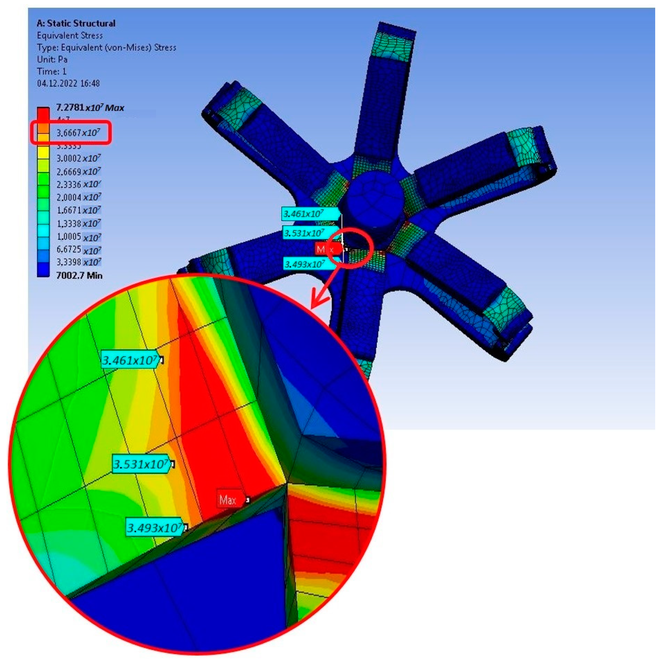
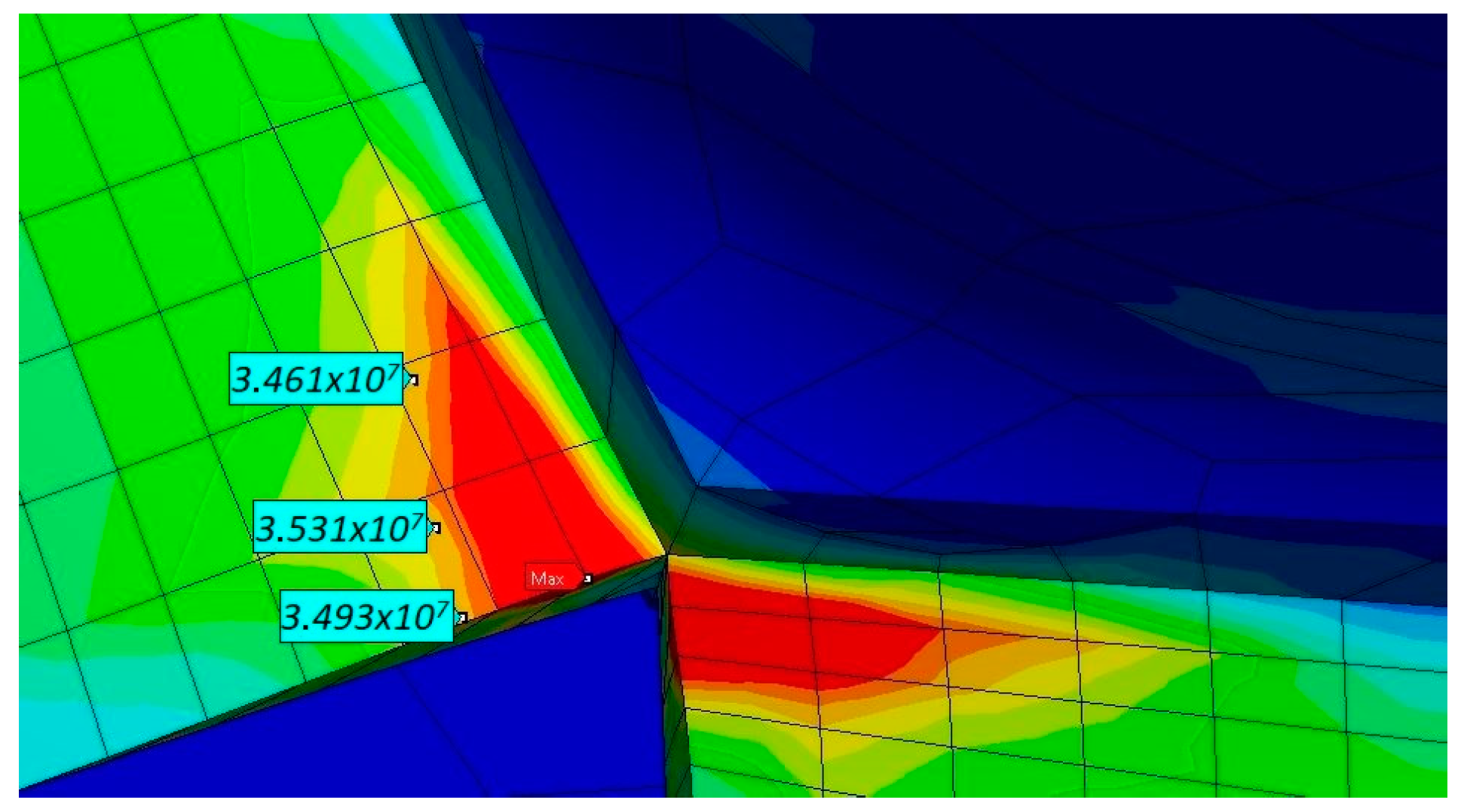
The initial scenario of the finite element analysis (FEA) involved subjecting the system to the maximum permissible torque while maintaining the joint at zero bend angle (
). The analysis was performed by clamping the output shaft and applying a torque of 4122 Nmm to the input shaft. The resulting stresses are presented in
Figure 7. The stress values are labeled starting from the closest point to the stress concentration points. The highest stress, obtained at the hinge’s edge, was determined to be 36.6 MPa. It is important to note that the hinge’s design limit was established based on the yield strength of the PP material, which stands at 36 MPa. A comparison between the FEA results and the analytical results exhibited a good agreement, with an error below 2%.
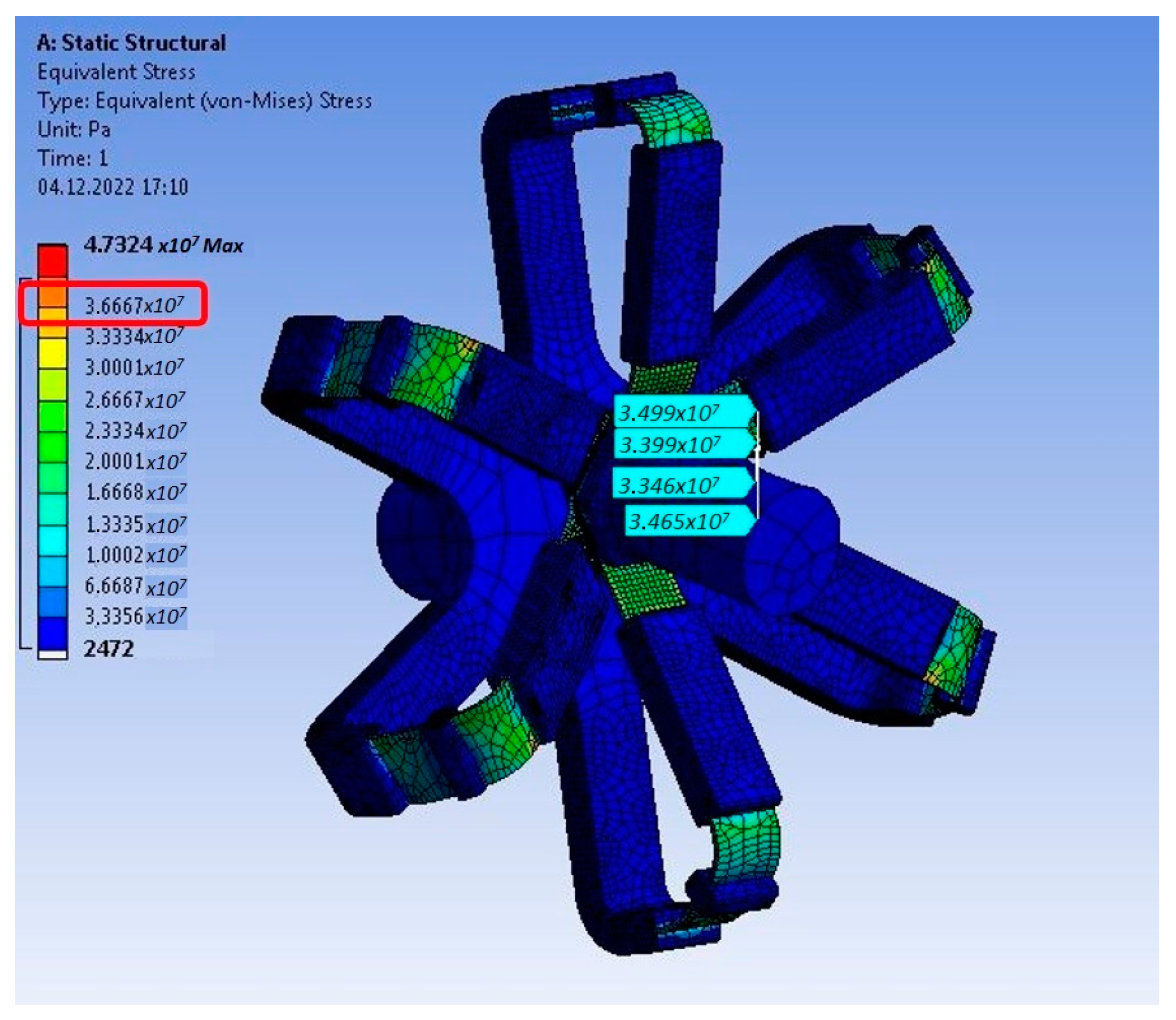
In the second phase of the FEA, the proposed joint underwent a shaft bending scenario. The joint was subjected to the maximum shaft angle (
), and the resulting stresses are illustrated in
Figure 8. Similar to the initial analysis, the obtained results from the shaft bending case exhibited a good agreement with both the analytical predictions and the FEA outcomes, showcasing an error of less than 5%. The finite element analysis conducted for the mechanism was performed for different intermediate angle values and presented in the following section as a comparison parameter.
6. Manufacturing of the Prototype and Test
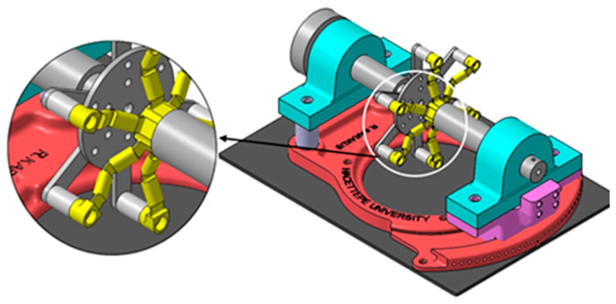
The experimental model is designed to be compatible with additive manufacturing methods, utilizing polypropylene (PP) as the material. It is important to note that the proposed fully compliant universal joint is suitable for manufacturing as a single piece using additive manufacturing techniques. However, the experimental set-up is manufactured in multiple parts to facilitate testing with different combinations. The model incorporates three cascades of fully compliant four-bar mechanisms, resulting in a hexagonal rigid body with six arms. The CAD design of the experimental set-up is presented in
Figure 10.
Increasing the number of arms also increases the torque capacity of the universal joint in a linear fashion. In the designed model, the compliant spherical joint has been eliminated. Removing this joint simplifies the manufacturing process, while the desired motion is achieved through the implementation of a sliding bearing in the test set-up. The angular sliding bearing of the base serves multiple purposes. It allows for adjustment of the bend angle and ensures that the center of rotation coincides with joint
O in
Figure 2. Thus, the degree of freedom (DoF) of the mechanism remains constant at 1. In the produced prototype, the link between
OA was removed to facilitate the ease of manufacturing. Removing this link increases the degree of freedom of the mechanism. However, the bearings that allow the shafts to rotate around the base of the experimental setup fulfill the centering role of the omitted link. Thus, the degree of freedom of the model produced as a prototype remains unchanged, and it does not affect the operation of the mechanism (
Figure 11). In
Figure 11,
SBJ represents the shaft bearings, and
Rb denotes the rotation radius of the output shaft. The amount of rotation is indicated by
β.
When incorporating the rotational capability of the shafts, the overall degree of freedom for the test setup increases to 2. This can be summarized as comprising the bending capability and shaft rotation. Production was carried out using a 3D printer to create the model. The production was performed using the Fused Deposition Modeling (FDM) method with PP material. During production, a speed of 36 mm/s, a nozzle diameter of 0.8 mm, a layer height of 0.3 mm, an extruder temperature of 235 °C, and a print bed temperature of 90 °C were used as the basic settings. Moreover, due to the low tendency of PP material to adhere to the build plate, a specific type of adhesive is employed to enhance the bonding strength between the printed part and the build plate. The total production time for the compliant segment was measured as 4 h and 50 min.
Likewise, the rigid part of the joint (output side) is manufactured using the FDM technique with ABS material. The fundamental parameter settings include a maximum printing speed of 45 mm/s, a layer height of 0.5 mm, a printing temperature of 245 °C, and a build plate temperature of 80 °C. The total elapsed time for production was recorded as 2 h and 20 min.
In this study, the fundamental mechanical properties of PP material were used as a basis while sizing the design and performing stress calculations. However, the experimental setup was produced using a 3D printer. Particularly, the fundamental mechanical properties of the material differ from the filament used in FDM-type printers. Additionally, various parameters such as manufacturing methodology, the specifications of the machine used for production, production parameters, environmental conditions, and production orientation significantly impact the characteristics of the produced part. In this respect, it is important to note that the produced prototype does not indicate an industrial application.
It should also be noted that both sides of the joint were manufactured within a closed enclosure to minimize the impact of the ambient conditions.
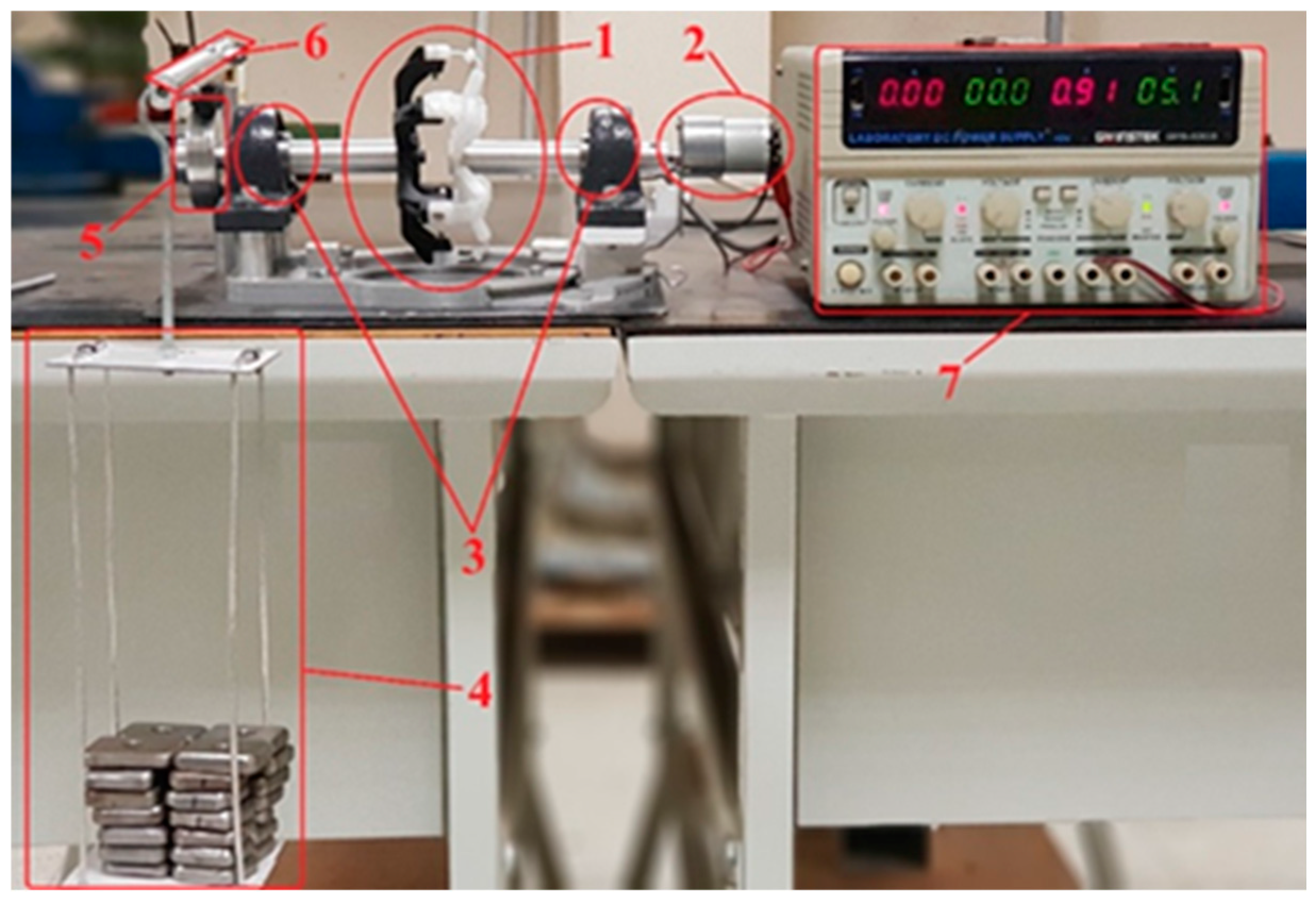
The experimental test setup is presented in
Figure 12. It consists of seven main parts:
Four-bar based compliant universal joint body with six arms;
Input torque generator by geared DC motor;
Input–output shaft bearings;
Known weight;
Resistive torque generator by brake pad and disc;
Braking lever;
Power supply.
Initially, the compliant hinges were examined at the maximum bend angle. In this process, the input shaft of the test setup was bent up to its maximum design limit and then slightly rotated. It was observed that the proposed mechanism operated as expected under these conditions, demonstrating its ability to perform effectively at the specified bend angle. Test set up is captured during operation and a video is presented as
Supplementary Materials.
In the next of the phase of prototype testing, the bend angle was adjusted to 0 degrees, and a 28.5 N force was applied to the brake lever, resulting in a resistive torque of 4100 Nmm at the output shaft. Once the resistive torque was set, the power supply was adjusted to a constant voltage, and the current was gradually increased. At a relatively high current, the input side of the joint began to rotate. The flexible hinges underwent elastic deformation just before the motion was transferred from the input to the output shaft, and the motion continued to be transferred thereafter.
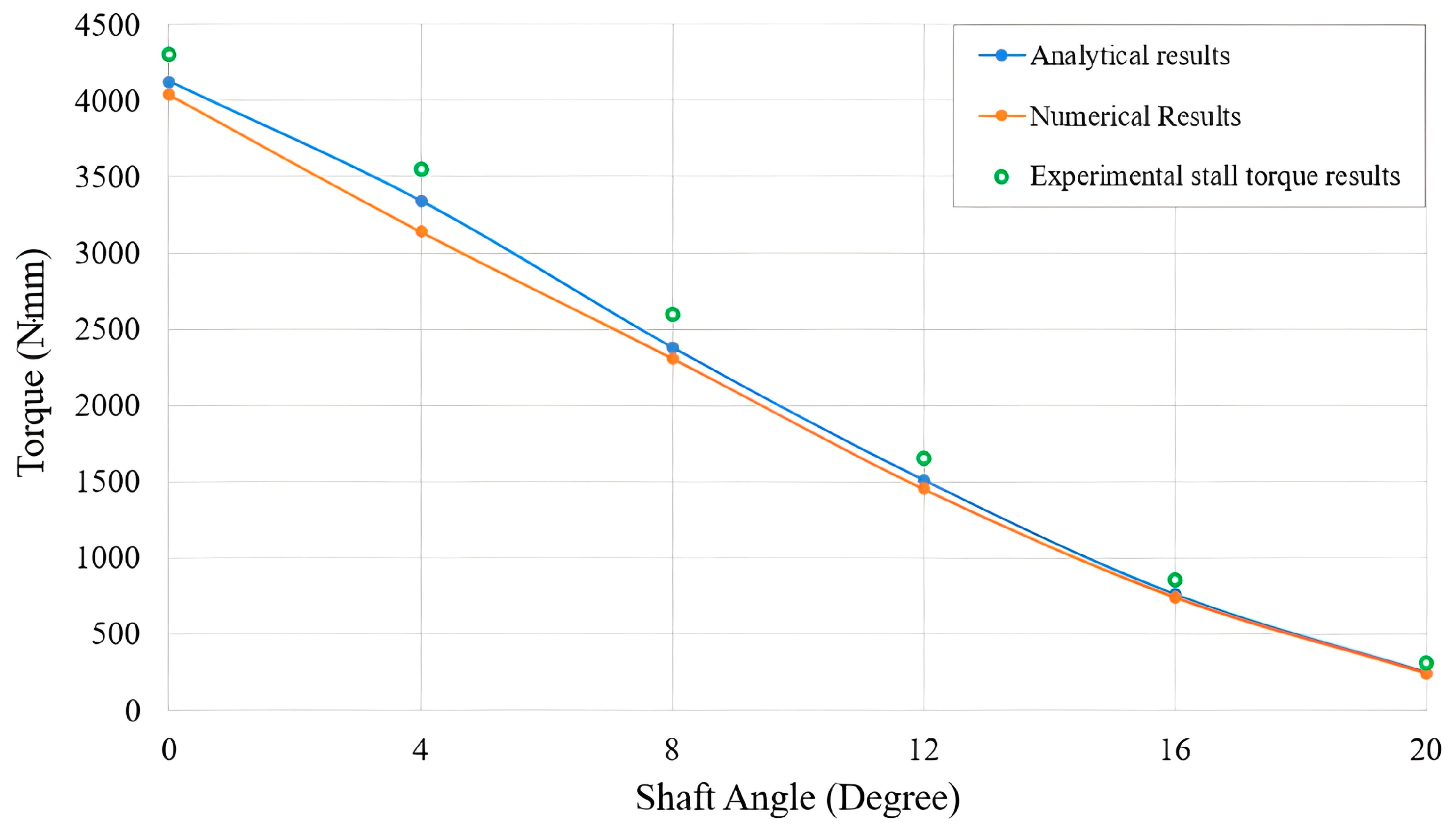
Although the system successfully transmitted the expected torque at a 0-degree bend angle, it was crucial to observe the upper limits of the mechanism for different bend angles. The resistive torque was continuously increased until the mechanism deformed, and the maximum value was noted as the stall torque limit of the mechanism. Furthermore, the stall torque limits of the mechanism were recorded for intermediate bend angles using 4-degree increments. The results are used as a comparison parameter alongside the analytical results and finite element analysis results, and are presented in
Figure 13.
According to
Figure 13, it is observed that the analytical methods and finite element analyses follow a similar trend. In nearly every angular position, the stall torques of the mechanism are slightly above the design torques as expected. The reason deviations are neither a fixed percentage nor a consistent difference is believed to be due to variations in manufacturing tolerances, manufacturing errors, or measurement errors.
Smooth operation is a crucial criterion in mechanism design. To assess the smoothness of the proposed joint under working conditions, the current drawn by the input motor was measured in real-time. Due to the insufficient refresh rate of the power supply’s current display, an oscilloscope was incorporated into the experimental setup to ensure precise data capture. The current at different bend angles was graphically observed from the oscilloscope at a frequency of 20 Hz. A variation of less than 10% in the current indicates that the input motor does not need to exert significantly greater torque at different angular positions. Consequently, the mechanism can be considered to operate smoothly.
As a final test, the proposed joint was also subjected to a slightly higher resistive torque (4250 Nmm) to achieve results similar to the accelerated life cycle tests. The joint was left in operation for 2 h at 200 rpm. After the 2-h test, the hinges were carefully examined, and no damage was observed.
It should be noted that the experiments were conducted at average room temperature. However, the tensile stress-strain behavior of this material is influenced by both strain rate and temperature. At lower temperatures, although the tensile strength is enhanced, the material exhibits a reduction in failure strain. Additionally, an increase in strain rate leads to higher flow stress [
32]. In industrial applications, it is important to consider these characteristics of the material.
The experiments conducted on the prototype have demonstrated both the functionality of the proposed design under real-world conditions and the validity of the applied design methodology.
7. Conclusions
This study introduces a novel compliant four-bar-based universal joint, which, to our knowledge, has not been investigated in the existing literature. It allows for easy adaptation by adjusting the width, thickness, and number of flexible segments to meet specific requirements for bend angles and output torque values. The prototype can be fabricated using either 3D printing techniques or injection molding techniques. An additional significant advantage is the scalability of compliant mechanisms, allowing them to be adjusted to various requirements by scaling up or down.
This study can be divided into four main steps. Firstly, a kinematic design method for the joint is presented. Next, the investigation of the flexible hinges is conducted to determine the stress induced by elastic deformation and resistive torque. Subsequently, the proposed joint is modeled, and the obtained results are validated through FEA. A comparison is made between the analytically obtained results and the FEA analysis results, revealing a good agreement. The experimental study forms a crucial part of this research, as it not only verifies the limits of the hinges but also ensures the smooth operation of the proposed four-bar based joint without any problem.
Upon conducting further investigations on the calculations, it can be concluded that the width of the hinges has a minimal impact on the stress experienced by the hinge as a result of the shaft bend angle. However, widening the hinge leads to a nonlinear increase in the torque capacity of the joint. Moreover, increasing the number of arms exhibits a linear increase in the torque capacity of the joint.
Another significant finding of this study is derived from the experimental setup. Although the velocity characteristics of the joint were not specifically investigated, it was observed that there is no angular speed variation between the input and output shafts. This observation can be attributed to the fixed locations of the flexible hinges relative to the output side of the joint. Therefore, it is expected that a constant velocity relationship exists between the input and output shafts.
8. Patents
The universal joint designed in this study is patent pending by the Turkish Patent Institute (TPE).


