Abstract
Cell micromanipulation is an important technique in the field of biomedical engineering. Microgrippers play a crucial role in connecting macroscopic and microscopic objects in micromanipulation systems. However, since the operated biological cells are deformable, vulnerable, and typically distributed in sizes ranging from micrometers to millimeters, it poses a huge challenge to microgripper performance. To solve this problem, this paper develops a dual-driven piezoelectric microgripper with a high displacement amplification ratio, large stroke, and parallel gripping. By adopting modular configuration, three kinds of flexure-based mechanisms, including the lever mechanism, Scott–Russell mechanism, and parallelogram mechanism are connected in series to realize three-stage amplification, which effectively makes up for the shortage of small output displacement of the piezoelectric actuator. At the same time, the use of the parallelogram mechanism also isolates the parasitic rotation movement, and realizes the parallel movement of the gripping jaws. In addition, the kinematics, statics, and dynamics models of the microgripper are established by using the pseudo-rigid body and Lagrange methods, and the key geometric parameters are also optimized. Finite element simulation and experimental tests verify the effectiveness of the developed microgripper. The results show that the developed microgripper allows an amplification ratio of 46.4, a clamping stroke of 2180 m, and a natural frequency of 203.1 Hz. Based on the developed microgripper, the nondestructive micromanipulation of zebrafish embryos is successfully realized.
1. Introduction
With the rapid development of biomedical engineering and the deepening of modern biology, many cell-level micromanipulations such as cell capture, cutting, separation, and injection have become research hotspots [1,2,3,4]. Due to the extremely small sizes of biological cells (ranging from 1 m to 1 mm) [5], it has exceeded the limit of manual operation. Although human beings can realize a series of cell operations with the help of microscopes, there still exist some unavoidable problems, such as poor repeatability of manual operations, difficulty in training professional operators, and low efficiency. Therefore, it is of great significance to develop a high performance cell micromanipulation robot system [6]. As a key component connecting macroscopic and microscopic systems, high-performance end-effectors play a vital role in the application of cell precision manipulation, and have attracted more and more attention from researchers [7,8].
As one of the popular end-effectors in robotic micromanipulation systems, microgrippers are used to clamp, hold, and release tiny objects without any damage, and have been widely applied in many high-precision fields such as optical fiber assembly [9,10] and microelectronics fabrication [11,12]. Because the task workspace is often limited, and the operated objects are cross-scale in size and irregular in shape, the microgripper needs to have a compact structure, large stroke, and high accuracy. So far, various types of microgrippers have been developed based on different actuations, such as electrostatic, shape memory alloy actuated, piezoelectric, and electromagnetic microgrippers [13]. Among these types, piezoelectric actuators (PEAs) are prevalent because of their advantages of fast response speed, high resolution, and large output force. However, the output motion of PEAs is relatively small, usually only tens of microns [14,15]. To overcome this problem, displacement amplification mechanisms (DAMs) are widely used to increase actuator output displacement [16]. In addition, closed-loop control schemes can be combined to eliminate the inherent hysteresis and creep behaviors of PEAs and to further improve the positioning accuracy [17,18,19,20,21].
In recent years, lots of piezo-driven microgrippers have been designed and developed using different types of DAMs. Wu et al. [22] designed an asymmetrical under-actuated microgripper that could perform twisting and gripping operations to the target simultaneously actuated by a single PEA. Sun et al. [23] combined the Scott–Russell mechanism and the lever mechanism to design a piezoelectric microgripper with the dimension of mm2, the maximum output displacement of 134 m, and the displacement amplification ratio (DAR) of 15.5. Wang et al. [24] developed a three-stage amplification piezo-driven microgripper through a bridge-type and two lever-type DAMs. The output displacement of the gripping jaws was 190 m, the DAR was 22.8, and the natural frequency was 953 Hz. In addition, considering the advantages of large clamping stroke and dexterous control, Yang et al. [25] proposed a dual-driven piezoelectric microgripper with a combination of lever-type and bridge-type DAMs, and achieved a maximum output displacement of 328.2 m and a DAR of 16.4. Guo et al. [26] designed a piezoelectric microgripper with three working modes with an output displacement of 1103.41 m and DAR of 55.17 by using a reconfigurable structure.
Although most reported microgrippers have obtained successful applications in different micromanipulation tasks, they are still not fully satisfactory in the solutions of large clamping stroke, big DAR, and high natural frequency but small dimensions. In fact, it is very challenging to take into account all these design requirements. The reason lies in that, in many special cases [23], due to the limited operating space, the geometry of the microgripper is also strictly constrained, which in turn affects the output displacement of the microgripper. Nevertheless, in order to break through the above bottleneck and improve the capability of microgripper for multi-scale micromanipulation tasks, a microgripper that allows the advantages of large stroke, big DAR, and high natural frequency has important research significance.
To this end, this paper proposes a dual-driven piezoelectric flexure-based microgripper with high DAR, large clamping stroke, and parallel clamping. With the modular configuration, three kinds of DAMs, including the lever mechanism, Scott–Russell mechanism, and parallelogram mechanism, are integrated in series to achieve three-stage amplification, effectively improving small output displacements of PEAs. Benefiting from the introduction of the parallelogram mechanism, it helps to reduce the parasitic rotation movement, and guarantees the parallel gripping. It needs to be mentioned that, although the three-stage amplification and Scott–Russell mechanism have been widely adopted in the field of compliant mechanisms [24,27,28,29], the proposed design is aimed at different applications, i.e., cell micromanipulation. In this context, it is a more challenging task for performance optimization and experimental tests since the biological cells are normally deformable and breakable. Indeed, to the authors’ knowledge, the abovementioned works have not been applied in this field. Moreover, from the testing results, the overall performance of the developed gripper is better than that of existing works in terms of the DAR, clamping stroke, and natural frequency, which effectively demonstrates that the proposed design is meaningful. Based on this configuration, the kinematics, statics, and dynamics models of the designed microgripper are established with the pseudo-rigid body and Lagrange methods, and the key geometric parameters are also optimized. Subsequently, finite element simulation and experimental tests are performed to validate the performance, and the actual gripping operation demonstrates its considerable potential in nondestructive cell micromanipulation applications. Thus, the main contribution of this work lies in the first attempt to adopt the dual-driven piezo microgripper with three-stage amplification to the cell micromanipulation, and fully validate the gripper’s efficacy by a series of experiments on zebrafish embryos.
The remainder of this paper is organized as follows. The microgripper configuration design is introduced in Section 2. The kinematics, statics, dynamics modeling, and parameter optimization are carried out in Section 3. The finite element simulation and experimental tests are presented in Section 4 and Section 5, respectively. Conclusions are drawn in Section 6.
2. Structural Design of the Microgripper
The new microgripper is designed as shown in Figure 1. It mainly consists of two PEAs, three types of motion amplification mechanisms, two gripping jaws, and a base. The motion amplification mechanisms comprise a lever mechanism, a Scott–Russell mechanism, and a parallelogram mechanism. Two preload screws are used to adjust the preload force between the PEAs and the compliant mechanism. The gripping jaws are directly connected to the fixed base through the parallelogram mechanism to isolate the parasitic deflection motions and ensure that their outputs are pure translation motions. The lever mechanism, the Scott–Russell mechanism, and the connection between the two mechanisms all adopt double-notched straight circular flexure hinges (SCFH). The parallelogram mechanism adopts single-notched SCFHs. The PEAs are embedded in the DAM to make the microgripper compact. The whole structure of the microgripper is symmetrical and each gripping jaw provides independent movement under the actuation of two PEAs, leading to the property of independent control. Compared with the traditional single-driven configuration, more dexterous clamping and releasing operations can be achieved by dual actuators. Moreover, in the proposed gripper, the horizontal direction motion is mainly considered to achieve the cell clamping and releasing operations. Although the coupling motion generated by the lever amplification mechanism is unavoidable in the vertical direction, it can be negligible for application in cell micromanipulation.

Figure 1.
Schematic diagram of the developed dual-driven piezoelectric microgripper.
The microgripper can implement the clamping and releasing operations through the extension and retraction motions of the PEAs, respectively. By applying a voltage to the PEA, a corresponding driving displacement is generated at the input end of the microgripper. The input displacement is amplified in the first stage by the lever mechanism. Then, the second amplification is carried out by the Scott–Russell mechanism. Finally, the parallelogram mechanism ensures that the microgripper output is pure translation while performing the third stage amplification. By combining the above three amplification mechanisms, the three-stage displacement amplification of the microgripper is realized.
3. Modeling and Parameter Optimization
3.1. Kinematics Modeling
According to the principle of the pseudo-rigid body model method [30], flexure hinges can be equivalent to ideal revolute joints with torsional springs, and the links connected by flexure hinges are regarded as rigid rods. Since the developed microgripper has a symmetrically distributed structure, only half of it is selected for analysis, as shown in Figure 2. In the figure, A, B, …, K represent the center of rotation of the flexure hinges; a, b, …, k represent the geometric parameters of the microgripper. Figure 3 describes the motion vectors of three amplification mechanisms of the microgripper. In the figure, the second-stage Scott–Russell mechanism has the property that the links CD, DF, and DE have the same length [31], i.e., . Moreover, the changes in displacements and angles of the microgripper are depicted in Figure 4, where and represent the input and output displacements of the microgripper, respectively, and their relationship can be expressed by
with the DAR . To obtain the amplification ratio of the microgripper, it needs to derive the amplification ratios of three motion mechanisms.

Figure 2.
(a) Distribution of the flexure hinges in the microgripper. (b) Equivalent model of half of the microgripper and its geometric parameters.

Figure 3.
Motion vector diagram of three amplification mechanisms.

Figure 4.
Diagram of changes in displacements and angles of the microgripper.
Firstly, for the first-stage lever mechanism, it can be found from Figure 3 that the instantaneous velocities of points B and C satisfy
where is the angular velocity of the link AC, , and denotes the lengths of links AB and AC, respectively. Therefore, the DAR of the lever mechanism obtained by Equations (2) and (3) is
Similarly, for the second-stage Scott–Russell mechanism, the instantaneous velocities of points C and F are given as follows:
where is the angular velocity of the link CF around the instantaneous rotation center O1, , and denotes the distances from O1 to C and F, respectively. Therefore, the DAR of the Scott–Russell mechanism obtained by the Equations (5) and (6) is
Moreover, for the third-stage parallelogram mechanism, the instantaneous velocities of points F, G, and I are given as follows:
where is the angular velocity of the link GF around the instantaneous rotation center O2, is the angular velocity of the link GH, , denotes the distances from O2 to F and G, , and denotes the lengths of links GH and HI, respectively. Therefore, the DAR of the parallelogram mechanism obtained by integrating Equations (8)–(10) is
Accordingly, the total DAR of the designed microgripper can be obtained by synthesizing Equations (4), (7) and (11) as
In addition, according to Figure 4, when the PEA produces an output displacement , the angular increment of the links AC, DE, CF, HI, and FG, and the corresponding rotation angles of the flexure hinges A, C, ⋯, K can be derived as follows:
where the included angle between the links GH and HI is calculated by . Here, denotes the radius of the hinge G, and denotes the thickness of the hinge H.
3.2. Statics Modeling
The static modeling of the microgripper is to describe the relationship between force and rotation of flexure hinges by using a pseudo-rigid body model. In this paper, two kinds of flexure hinges are used in the microgripper, i.e., double-notch straight circular flexure hinges (e.g., A, C, D, E, F, G), and single-notch straight circular flexure hinges (e.g., H, I, J, K). According to the previous results [32], these two kinds of hinges satisfy the following relations:
where is the stiffness of flexure hinges, E represents the elastic modulus of the material, and n, , and represent the width, thickness, and radius of the flexure hinge, respectively.
According to the virtual work principle, the relationship between the input force , the input displacement , the output force , and the output displacement can be expressed as
where denotes the total virtual work of the system, and and indicate the virtual work generated by the input and output forces, respectively. denotes the virtual work caused by the torques on the flexure hinges, where the torque generated by the i-th hinge is calculated by
Moreover, the input force and the input displacement also satisfy the following equation:
where is the input stiffness of the microgripper.
Let , and combine Equations (13)–(19) and (21), the following equation can be obtained:
with the constant coefficient
During the micromanipulation of biological cells, the movements of the microgripper consist of two stages, i.e., the approaching stage and the grasping stage. In the approaching stage, the gripping jaws are open until they contact with the cell, and the output force is zero, so the input stiffness can be obtained from Equations (23) and (24) as
When the microgripper works in the grasping stage, the gripping jaws are closed, and contact with the cell. The input and output displacements are almost no longer changed and nearly to be a fixed value. According to Equations (23) and (24), the input and output force relationship can be derived:
It is seen that the output force keeps in a linear relationship with the input force , and the larger the DAR of the microgripper, the smaller the output force . Moreover, it also implies that the input stiffness becomes larger when working in the grasping stage.
In order to analyze the stress condition of each flexure hinge, it is necessary to determine their reaction forces and torques. The force analysis of the designed microgripper is shown in Figure 5. The static equilibrium analysis is performed on each rigid link, and the following equations are finally derived:
where and represent the force of flexure hinges in the x and y directions, and represents the torque of flexure hinges obtained by Equation (22), respectively.
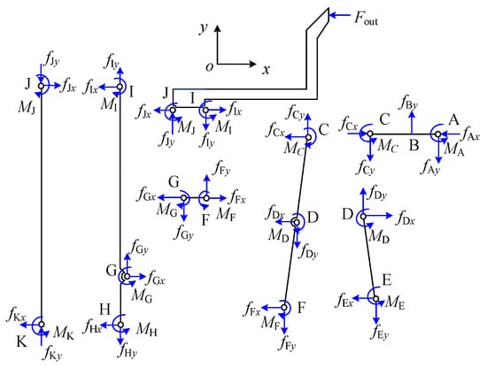
Figure 5.
Static analysis of the microgripper.
Generally, the maximum stress occurs at the thinnest region of the flexure hinge, and is produced by the combined action of bending and tension. According to Equations (13)–(19) and (28)–(36), the maximum stress of each hinge adopted in the microgripper can be predicted by
The maximum stress of the flexure hinge should be less than the allowable stress, i.e.,
where is the yield strength of the material, and is the safety factor.
3.3. Dynamics Modeling
Benefitting from flexure hinges, there exists no friction in the microgripper, so the system can be considered to be undamped [33]. In this paper, the Lagrange equation is used to establish the dynamics model of the microgripper and can be expressed as
with the Lagrange function
where T is the kinetic energy of all moving links of the microgripper, and can be expressed as
where , , , , and represent the moment of inertia of links AC, DE, CF, FG and HI, respectively. is the mass of the output end (i.e., gripping jaw) of the microgripper. V is the potential energy of all hinges in the microgripper, and can be represented as
According to the Equation (39), the dynamic equation of the system are finally obtained by combining Equations (13)–(19), (25) and (40)–(42) as
where M, K, F represent the equivalent mass, stiffness, and generalized force of the microgripper, respectively, which are given by
Thus, the natural frequency of the system is calculated by
3.4. Parameter Optimization
Since the flexure hinges play an important role in the movement transmission, the selection of parameters greatly affects the performance of the microgripper. In this regard, parameters of flexure hinges (i.e., the thickness t and radius r) are selected as the design variables to optimize the natural frequency of the microgripper. As for other structural parameters, they have been designed and listed in Table 1 for simplification of the analysis. Further, considering the overall configuration and manufacturing conditions of the microgripper, the natural frequency should be optimized as high as possible under the constraints of the specified parameter ranges, which is beneficial to improve the dynamic performance of the microgripper. It is worth noting that since the structure of the microgripper is symmetrical, half of it is optimized. Once the optimal parameters are obtained, the other half will use the same parameters.

Table 1.
Structure parameters for the designed microgripper.
The optimization design process of the microgripper can be described as follows:
- Set as a vector to be optimized, where the variables and correspond to the radius and thickness of double-notched SCFHs (i.e., A, C, D, E, F, G); and correspond to the radius and thickness of single-notched SCFHs (i.e., H, I, J, K).
- The optimization goal is to maximize the first-order natural frequency, i.e., .
- The following kinds of constraints are prescribed:
- (a)
- Size constraints: , .
- (b)
- Stiffness constraint: , where is the stiffness of PEAs. Too large input stiffness will decrease the output displacement of PEA, leading to the reduction of motion range of the microgripper.
- (c)
- Strength constraint: the maximum stress during the movement of the microgripper should be less than the maximum allowable stress, i.e., .
In this paper, the MATLAB optimization toolbox is adopted to optimize the parameters. The material of the microgripper uses the Aluminum alloy (type: Al-7075-T6) with the main properties [34]: the density is 2810 kg/m3, Young’s modulus is 71.7 GPa, Poisson’s ratio is 0.33, and yield strength is 503 MPa. The safety factor chooses . The initial value of is set as , and the final optimization results are obtained by: mm, mm, mm. According to the optimized results and designed parameters in Table 1, the first-order natural frequency can be calculated from Equation (47) as Hz.
4. Finite Element Simulation Analysis
To validate the optimized parameters and performance of the microgripper, the finite element simulation is conducted with Ansys software in version R19.0. The static structural analysis module in Ansys Workbench is used to evaluate the static performance of the microgripper, whereas the modal analysis module is employed to assess the dynamic performance.
Firstly, considering the fact that the PEAs used in the proposed microgripper can not provide the ideal maximum output displacement of 60 m under variable loads, an input displacement of 10 m is thus applied to the half of the microgripper to verify the amplification ratio. The static simulation results are shown in Figure 6. It is found from Figure 6a that the output displacement of the gripping jaw in the horizontal direction is 548.11 m, which achieves a large amplification ratio of 54.8. According to Equation (12), the theoretical amplification ratio can also be calculated as 55.5. By contrast, there only is an error of 1.28%, clearly showing the effectiveness of the designed parameters in Table 1. Moreover, from Figure 6b, it is also found that the parasitic motion of the gripping jaw in the vertical direction is 4.9 m. Therefore, the cross-coupling ratio is only 0.89%, which can ensure a firm translational clamping operation on a wide range of micro-objects.
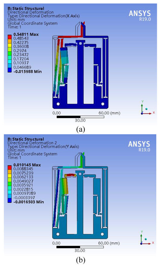
Figure 6.
Static analysis results: (a) X-direction deformation; (b) Y-direction deformation.
Secondly, to test the structural strength of the microgripper, a couple of input displacements of 10 m are applied to the microgripper simultaneously. Through the static structural analysis, the stress distribution of the microgripper is depicted in Figure 7. It is observed that the stress concentration mainly occurs at the flexure hinge A. The maximum stress is 221.43 MPa, which is less than the allowable stress of 335.33 MPa.
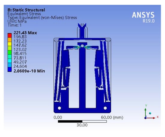
Figure 7.
Stress distribution of the microgripper.
Finally, in order to examine the dynamic performance of the microgripper, the modal analysis is carried out, and the corresponding first six natural frequencies are shown in Figure 8. It can be seen that the first two modal frequencies of the microgripper reflect the opening and closing motions of the left and right gripping jaws, respectively, which are consistent with the clamping movement of the microgripper. According to the previous result, the first-order natural frequency calculated by the theoretical model is 228.69 Hz; thus, the relative error is less than 2.3% compared with the results of finite element analysis, which indicates the validity of the theoretical dynamic model.
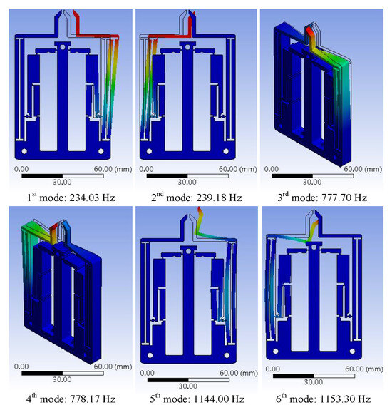
Figure 8.
Finite element analysis results for first six modes of the microgripper.
5. Experimental Verification
5.1. Experimental Setup
The experimental setup is shown in Figure 9a for validating the performance of the developed microgripper on cell microgripping. The mechanical structure of the microgripper is fabricated through wire electrical discharge machining with the aluminum alloy material of Al-7075-T6. Two PEAs (type: PSt150/5/60 VS10, Core-Tomorrow Co., Harbin, China) are adopted to actuate the microgripper, which can provide a nominal output displacement of 60 m at the maximum driving voltage of 150 V. They are pre-tightened by screws on the microgripper and actuated by two voltage amplifier (model: E53.A from the Core-Tomorrow Co.). The total weight of the developed microgripper is finally about 123.8 g. The laser displacement sensor (model: LK-H022 from Keyence, Inc., Wauwatosa, WI, USA) is used to measure the output displacement of the microgripper, and its output voltage signal is first passed through the sensor conditioner (model: LK-G5001 from Keyence, Inc.), and then acquired by the A/D channel of a data acquisition card (model: PCI-6229 with 16-bit A/D and D/A converters from NI Co., Tokyo, Japan). The control voltage signals are generated by the D/A channel and then amplified 15 times by voltage amplifiers to drive the PEAs to achieve the movement of the microgripper. Control algorithms are developed with MATLAB/Simulink software in version R2021a on the Desktop Real-Time environment. In order to reduce external vibration interference, the whole experimental setup is fixed on a vibration isolation table.
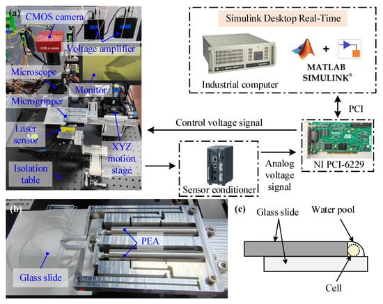
Figure 9.
(a) Experimental setup for cell microgripping. (b) Structure of the developed microgripper. (c) Schematic diagram of cell immobilization.
Moreover, a vision imaging system consisting of an optical microscope, a CMOS camera, and a monitor is also utilized to capture the microgripper’s motions. An XYZ motion stage driven by three DC stepping motors with embedded encoders is introduced to adjust the relative distance between the microgripper and the cells, as shown in Figure 9b. Each axis has a motion range of 30 mm and an accuracy of 0.25 m. Cells are placed and immobilized on the glass slides by the means in Figure 9c.
5.2. Open-Loop Tests of the Microgripper
To verify the performance of the microgripper at the free movement state, the open-loop tests are first conducted. Since the microgripper design is symmetric, one PEA is driven with a sinusoidal signal of 0.1 Hz and an amplitude of 150 V. The output displacements of the input and output ends of the microgripper are obtained as shown in Figure 10. The open-loop experimental results show that the output end of the microgripper can reach a maximum output displacement of about 1090 m when the input end provides a maximum displacement of 23.5 m. Thus, it implies that the microgripper makes it possible to achieve a total clamping stroke of 2180 m, and a DAR of 46.4. Compared with the FEA and theoretical amplification ratios, the deviations of the experimental result are 15.3% and 16.4%, respectively. The main reason lies in that the theoretical calculation only considers the bending deformation of the flexure hinges, and does not consider other deformations. The experimental result is lower than the FEA result, mainly due to the manufacturing accuracy of the circular flexure hinges, and the assembly error from the offset or incline of inputs. It is worth mentioning that the maximum displacement of the input end is much smaller than the nominal output displacement 60 m of PEA, which is caused by the input stiffness of the microgripper.
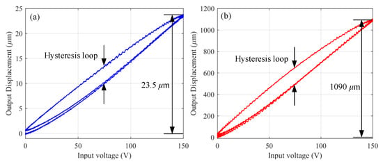
Figure 10.
Output displacement responses of the microgripper with the applied voltage. (a) The input end. (b) The output end.
Furthermore, it is also obviously found from Figure 10 that the nonlinear hysteresis effect resulting from the PEA appears when depicting the output displacements with respect to the input voltage in the open-loop experimental tests. Such strongly nonlinear behavior severely degrades the motion accuracy of the microgripper unless it is compensated effectively.
In addition, a swept voltage signal with a frequency varying from 1 to 300 Hz and an amplitude of 0.3 V is used to obtain the natural frequency. Figure 11 shows the frequency analysis results of the microgripper. It is found that the first-order natural frequency of the microgripper is approximately 203.1 Hz, which is 11.2% smaller than the theoretical value and 13.2% smaller than the FEA value. The difference mainly results from the fact that both the theoretical calculation and the FEA simulation ignore the mass of PEAs.

Figure 11.
Frequency response of the developed microgripper.
5.3. Closed-Loop Tests of the Microgripper
The above open-loop testing results in Figure 10 disclose that there exists severe hysteresis nonlinearity in the microgripper. In view of this, the closed-loop experiments are next conducted to verify the performance of the developed microgripper on the hysteresis compensation.
The tracking performance of the microgripper is tested with a closed-loop proportional-integral (PI) feedback control method, and the corresponding controller gains are set as , and . Without loss of generality, two kinds of step and sinusoidal signals are selected for example. The step response of the microgripper is firstly investigated with a duration of 5 s and an amplitude of 750 m, as shown in Figure 12a, and the corresponding control voltage is given in Figure 12b. It is obviously found that the designed microgripper can track the reference command fast under the PI controller, and takes the settling time of 0.23 s to converge within 3.14 m. Furthermore, to evaluate the tracking performance in response to the sinusoidal signal, a 1 mm amplitude and 1-Hz frequency desired displacement is selected. The experimental results are shown in Figure 12c,d. Similarly, the microgripper also performs well with the root-mean-square error of 8.43 m and the maximum percentage error of 2.47% relative to the movement stroke. The above results fully illustrate the fast convergence and stable motion-tracking performance of the designed microgripper.
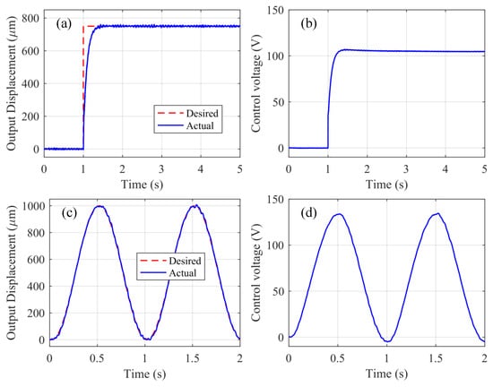
Figure 12.
Closed-loop tracking results of the microgripper. (a,b) Step signal tracking results. (c,d) 1-Hz sinusoidal signal tracking results.
5.4. Applications to Cell Micromanipulation
In order to evaluate the gripping ability of the developed microgripper, applications to cell micromanipulation for zebrafish embryos are also tested. As a class of widely used cell models in biomedical fields, zebrafish embryos are introduced here due to their advantages of transparent and large embryos (radii about 450–500 m). To guarantee the consistency of the experimental objects, 100 zebrafish embryos at the pharyngula stage with radii of about 500 m are collected as samples.
Figure 13 provides a microscopic observation of the cell gripping process, including the non-gripping state and the gripping state, where the gripper tracks the step signal in Figure 12. As shown in this figure, the gripping jaws of the developed microgripper are parallel before and after gripping the cell, which demonstrates that the gripping jaws guarantee parallel movement. Moreover, under the action of the closed-loop PI control, the cell can be clamped and released carefully without mechanical damage. To further validate the control bandwidth and the cell grasping performance, sinusoidal tracking signals with different frequencies are tested as shown in Figure 14. It is found from Figure 14a that the closed-loop microgripper provides a control bandwidth of about 23.1 Hz. Accordingly, the cell grasping experiments are also conducted under different frequencies, and the corresponding statistic results are given in Figure 14b. To demonstrate the consistency of performance, each frequency is repeatedly tested ten times. It is clearly observed that the developed microgripper can guarantee firm and successful grasping at the bandwidth of about 20 Hz. But when the input frequency increases, the success rate goes down. Once the frequency exceeds 40 Hz, the gripper can not grasp the cell successfully due to the attenuation of the output displacement amplitude. Nevertheless, it still validates the effectiveness of the designed microgripper on cell micromanipulation at the bandwidth of about 20 Hz, which is sufficient for most cell micromanipulation applications. In view of the successful gripping operation, the microgripper has considerable potential for the applications of biomedical engineering in handling micro-objects.

Figure 13.
Microscopic images of cell micromanipulation by the developed microgripper. (a) Before gripping the cell. (b) After gripping the cell. (c) Releasing the cell. From the figure, it is observed that the gripper can clamp and release the cell successfully without mechanical damage.
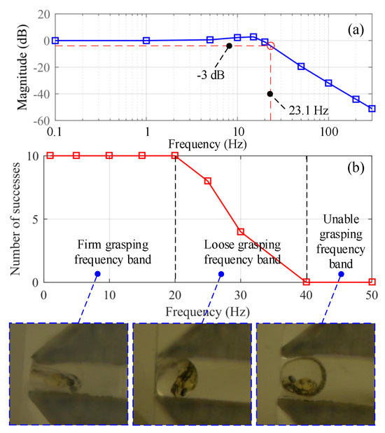
Figure 14.
(a) Closed -loop control bandwidth of the developed microgripper, where the red dashed lines represent that the bandwidth is 23.1 Hz under the magnitude of −3 dB. (b) Statistical results of cell grasping experiments under different frequencies, where each frequency is repeatedly tested for ten times.
5.5. Discussion
According to the above experimental results, the superiority of the proposed microgripper is significant in terms of the dexterity and applicability of cell micromanipulation. However, there also exist several issues to be solved to improve the applicability of this microgripper system. The first issue is that the process of cell micromanipulation only considers the output displacement rather than the gripping force of the microgripper. But to achieve better precise cell operation, the force control and force protection mechanism are also very important and have been taken into account in other reported microgrippers [35,36]. Therefore, force sensors and constant force mechanisms will be added in the future to achieve hybrid force and position control. The second issue lies in that the relative position between the cells and the microgripper is adjusted by the XYZ motion stage under the guidance of the operator. This operation method is time-consuming and laborious. To achieve automatic and batched cell micromanipulation, in future work, a visual positioning method for zebrafish embryos and microgrippers will be a positive research direction to implement automatic gripping and increase operational efficiency. Moreover, since the biological cells are adhesive objects, the adhesive effect will be obvious and lead to a challenge for the pick–place process. Therefore, the gripper tips should have some special treatments for a wider class of cell micromanipulation. The last but not least issue is the limitation of control performance of the PI controller. It is clearly found from Figure 11 and Figure 14 that the control bandwidth of the closed-loop microgripper is much smaller than the natural frequency. It results from the fact that the hysteresis nonlinearity gets worse with the increase of input frequencies, which is difficult for the PI control to solve effectively. Therefore, a robust adaptive controller will also be presented to suppress the high-frequency hysteresis nonlinearity in future work.
6. Conclusions
This paper has proposed a new type of dual-driven piezoelectric microgripper with high DAR, large clamping stroke, and parallel movement for cell micromanipulation. The high amplification ratio has been achieved through a three-stage flexure-based amplification mechanism, effectively overcoming the shortcomings of small strokes of PEAs. By using the parallelogram mechanism, the parallel movement of the gripping jaws has been guaranteed. Based on the PRBM and Lagrange approaches, the kinematics, statics, and dynamics models of the microgripper have been established, and the amplification ratio, input stiffness, and natural frequency of the microgripper have been also analyzed, respectively. The crucial microgripper parameters have been determined by optimization design with the first-order mode frequency as the objective function. The static and dynamic characteristics of the microgripper have been analyzed using FEA and experiments to verify the performance. The experimental results show that the proposed microgripper provides an amplification ratio of 46.4, a clamping stroke of 2180 m, and a natural frequency of 203.1 Hz. Moreover, to suppress the nonlinear hysteresis behavior induced by PEAs, the closed-loop PI feedback control has been integrated to improve motion accuracy. Benefiting from the superior performance, the developed microgripper has been successfully utilized to grip the biological cells. Future work will focus on the realization of the hybrid control of the microgripper with the feedback of the gripping force and the tip displacement.
Author Contributions
Conceptualization, B.L. and S.K.; Methodology, S.K.; Software, L.Z.; Validation, D.H., C.Y. and Z.Z.; Formal Analysis, B.L.; Investigation, L.Z.; Resources, S.K.; Data Curation, Z.Z.; Writing—Original Draft Preparation, B.L.; Writing—Review and Editing, S.K.; Visualization, D.H.; Supervision, S.K.; Project Administration, S.K.; Funding Acquisition, S.K. All authors have read and agreed to the published version of the manuscript.
Funding
This work was supported by the National Natural Science Foundation of China under Grant 52405117, the Natural Science Foundation of Jiangsu Province under Grant BK20220449, the Startup Foundation for Introducing Talent of NUIST under Grant 2022r092, and the NUIST Students’ Platform for Innovation and Entrepreneurship Training Program under Grant 202310300069Z.
Data Availability Statement
The original contributions presented in the study are included in the article, further inquiries can be directed to the corresponding author.
Acknowledgments
The authors would like to thank the Editor and the anonymous reviewers for their valuable comments and kind suggestions to improve the quality of this paper.
Conflicts of Interest
The authors declare no conflicts of interest.
References
- Kodera, S.; Watanabe, T.; Yokoyama, Y.; Hayakawa, T. Microgripper using soft microactuators for manipulation of living cells. Micromachines 2022, 13, 794. [Google Scholar] [CrossRef] [PubMed]
- Kang, S.; Song, Z.; Yang, X.; Li, Y.; Wu, H.; Li, T. A rate-dependent cell microinjection model based on membrane theory. J. Biomech. Eng. 2023, 145, 091007. [Google Scholar] [CrossRef] [PubMed]
- Dai, C.; Zhuang, S.; Shan, G.; Liu, H.; Wang, Y.; Ru, C.; Sun, Y. Automated piezo-assisted sperm immobilization. IEEE Trans. Autom. Sci. Eng. 2023, 21, 3. [Google Scholar] [CrossRef]
- Shan, G.; Dai, C.; Liu, H.; Wang, X.; Dou, W.; Ru, C.; Sun, Y. Robotic blastocyst biopsy. IEEE/ASME Trans. Mechatronics 2022, 28, 1372–1383. [Google Scholar] [CrossRef]
- Guo, X.; Zhang, Y.; Jin, D.; Zhou, M. A review of single-cell pose adjustment and puncture. Adv. Intell. Syst. 2022, 4, 2200096. [Google Scholar] [CrossRef]
- Zhang, Z.; Wang, X.; Liu, J.; Dai, C.; Sun, Y. Robotic micromanipulation: Fundamentals and applications. Annu. Rev. Control Robot. Auton. Syst. 2019, 2, 181–203. [Google Scholar] [CrossRef]
- Shakoor, A.; Gao, W.; Zhao, L.; Jiang, Z.; Sun, D. Advanced tools and methods for single-cell surgery. Microsyst. Nanoeng. 2022, 8, 47. [Google Scholar] [CrossRef]
- Kang, S.; Yang, X.; Li, Y.; Wu, H.; Li, T. A fractional viscoelastic mechanical model for speed optimization of robotic cell microinjection. IEEE/ASME Trans. Mechatronics, 2024; early access. [Google Scholar]
- Zhang, J.; Lu, K.; Chen, W.; Jiang, J.; Chen, W. Monolithically integrated two-axis microgripper for polarization maintaining in optical fiber assembly. Rev. Sci. Instruments 2015, 86, 025105. [Google Scholar] [CrossRef]
- Lyu, Z.; Xu, Q. Design of a new bio-inspired dual-axis compliant micromanipulator with millimeter strokes. IEEE Trans. Robot. 2022, 39, 470–484. [Google Scholar] [CrossRef]
- Komati, B.; Clévy, C.; Lutz, P. High bandwidth microgripper with integrated force sensors and position estimation for the grasp of multistiffness microcomponents. IEEE/ASME Trans. Mechatronics 2016, 21, 2039–2049. [Google Scholar] [CrossRef]
- Shi, Q.; Yu, Z.; Wang, H.; Sun, T.; Huang, Q.; Fukuda, T. Development of a highly compact microgripper capable of online calibration for multisized microobject manipulation. IEEE Trans. Nanotechnol. 2018, 17, 657–661. [Google Scholar] [CrossRef]
- Verotti, M.; Dochshanov, A.; Belfiore, N.P. A comprehensive survey on microgrippers design: Mechanical structure. J. Mech. Des. 2017, 139, 060801. [Google Scholar] [CrossRef]
- Sabarian, D.V.; Karthikeyan, P.; Muthuramalingam, T. A review on control strategies for compensation of hysteresis and creep on piezoelectric actuators based micro systems. Mech. Syst. Signal Process. 2020, 140, 106634. [Google Scholar] [CrossRef]
- Kang, S.; Wu, H.; Li, Y.; Yang, X.; Yao, J. A fractional-order normalized bouc–wen model for piezoelectric hysteresis nonlinearity. IEEE/ASME Trans. Mechatronics 2022, 27, 126–136. [Google Scholar] [CrossRef]
- Ding, B.; Li, X.; Li, C.; Li, Y.; Chen, S.C. A survey on the mechanical design for piezo-actuated compliant micro-positioning stages. Rev. Sci. Instruments 2023, 94, 101502. [Google Scholar] [CrossRef] [PubMed]
- Dinh, T.X.; Ahn, K.K. Adaptive-gain fast nonsingular terminal sliding mode for position control of a piezo positioning stage. J. Syst. Control Eng. 2018, 232, 994–1014. [Google Scholar] [CrossRef]
- Kang, S.; Wu, H.; Yang, X.; Li, Y.; Chen, B.; Yao, J. Nonlinearities compensation of a parallel piezostage using discrete-time sliding mode predictive control with decoupling and damping properties. Mech. Syst. Signal Process. 2023, 192, 110206. [Google Scholar] [CrossRef]
- Kang, S.; Wu, H.; Yang, X.; Li, Y.; Pan, L.; Chen, B. Fractional robust adaptive decoupled control for attenuating creep, hysteresis and cross coupling in a parallel piezostage. Mech. Syst. Signal Process. 2021, 159, 107764. [Google Scholar] [CrossRef]
- Li, L.; Kang, S.; Bai, D.; Wu, H.; Yu, J. Robust high-precision tracking control for a class of nonlinear piezoelectric micropositioning systems with time-varying uncertainties. Meas. Control 2023, 56, 1396–1409. [Google Scholar] [CrossRef]
- Yu, S.; Ma, J.; Wu, H.; Kang, S. Robust precision motion control of piezoelectric actuators using fast nonsingular terminal sliding mode with time delay estimation. Meas. Control 2019, 52, 11–19. [Google Scholar] [CrossRef]
- Wu, Z.; Wang, Y.; Chen, M.; Ding, B. Design, analysis, and experimental investigations of an asymmetrical under-actuated micro-gripper. J. Intell. Mater. Syst. Struct. 2024, 35, 960–970. [Google Scholar] [CrossRef]
- Sun, X.; Chen, W.; Tian, Y.; Fatikow, S.; Zhou, R.; Zhang, J.; Mikczinski, M. A novel flexure-based microgripper with double amplification mechanisms for micro/nano manipulation. Rev. Sci. Instruments 2013, 84, 085002. [Google Scholar] [CrossRef] [PubMed]
- Wang, F.; Liang, C.; Tian, Y.; Zhao, X.; Zhang, D. Design of a piezoelectric-actuated microgripper with a three-stage flexure-based amplification. IEEE/ASME Trans. Mechatronics 2014, 20, 2205–2213. [Google Scholar] [CrossRef]
- Yang, Y.L.; Wei, Y.D.; Lou, J.Q.; Xie, F.R.; Fu, L. Development and precision position/force control of a new flexure-based microgripper. J. Micromech. Microeng. 2015, 26, 015005. [Google Scholar] [CrossRef]
- Guo, Z.; Lyu, Z.; Xu, Q. Design of a piezoelectric-driven microgripper with three working modes. IEEE/ASME Trans. Mechatronics 2023, 29, 260–270. [Google Scholar] [CrossRef]
- Hong, Y.; Wu, Y.; Jin, S.; Liu, D.; Chi, B. Design and analysis of a microgripper with three-stage amplification mechanism for micromanipulation. Micromachines 2022, 13, 366. [Google Scholar] [CrossRef]
- Tang, H.; Li, J.; Jia, Y.; Gao, J.; Li, Y. Development and testing of a large-stroke nanopositioning stage with linear active disturbance rejection controller. IEEE Trans. Autom. Sci. Eng. 2021, 19, 2461–2470. [Google Scholar] [CrossRef]
- Liang, C.; Wang, F.; Shi, B.; Huo, Z.; Zhou, K.; Tian, Y.; Zhang, D. Design and control of a novel asymmetrical piezoelectric actuated microgripper for micromanipulation. Sens. Actuators Phys. 2018, 269, 227–237. [Google Scholar] [CrossRef]
- Verotti, M. A pseudo-rigid body model based on finite displacements and strain energy. Mech. Mach. Theory 2020, 149, 103811. [Google Scholar] [CrossRef]
- Wu, H.; Lai, L.; Zhang, L.; Zhu, L. A novel compliant XY micro-positioning stage using bridge-type displacement amplifier embedded with Scott–Russell mechanism. Precis. Eng. 2022, 73, 284–295. [Google Scholar] [CrossRef]
- Ling, M.; Howell, L.L.; Cao, J.; Chen, G. Kinetostatic and dynamic modeling of flexure-based compliant mechanisms: A survey. Appl. Mech. Rev. 2020, 72, 030802. [Google Scholar] [CrossRef]
- Ling, M.; Zhang, X. Coupled dynamic modeling of piezo-actuated compliant mechanisms subjected to external loads. Mech. Mach. Theory 2021, 160, 104283. [Google Scholar] [CrossRef]
- Das, T.K.; Shirinzadeh, B.; Al-Jodah, A.; Ghafarian, M.; Pinskier, J. Computational parametric analysis and experimental investigations of a compact flexure-based microgripper. Precis. Eng. 2020, 66, 363–373. [Google Scholar] [CrossRef]
- Wei, Y.; Xu, Q. Design and testing of a new force-sensing cell microinjector based on small-stiffness compliant mechanism. IEEE/ASME Trans. Mechatronics 2020, 26, 818–829. [Google Scholar] [CrossRef]
- Shan, Y.; Ding, B.; Zhong, J.; Li, Y. Design and optimization of a decoupled serial constant force microgripper for force sensitive objects manipulation. Robotica 2023, 41, 2064–2078. [Google Scholar] [CrossRef]
Disclaimer/Publisher’s Note: The statements, opinions and data contained in all publications are solely those of the individual author(s) and contributor(s) and not of MDPI and/or the editor(s). MDPI and/or the editor(s) disclaim responsibility for any injury to people or property resulting from any ideas, methods, instructions or products referred to in the content. |
© 2024 by the authors. Licensee MDPI, Basel, Switzerland. This article is an open access article distributed under the terms and conditions of the Creative Commons Attribution (CC BY) license (https://creativecommons.org/licenses/by/4.0/).