Article

Design, Testing, and Optimization of a Filling-Type Silage Crushing, Shredding, and Baling Integrated Machine

1
College of Mechano-Electronic Engineering, Gansu Agricultural University, Lanzhou 730070, China
2
Department of Mechanical Engineering, College of Engineering, Texas A&M University, Corpus Christi Campus, Corpus Christi, TX 78412, USA
*
Author to whom correspondence should be addressed.
Machines 2025, 13(3), 228; https://doi.org/10.3390/machines13030228
Submission received: 6 February 2025 / Revised: 8 March 2025 / Accepted: 10 March 2025 / Published: 12 March 2025
(This article belongs to the Section Machine Design and Theory)

Abstract

To address the limitations of large silage machines in hilly and small-scale farming regions and the inefficiencies of existing small-scale crushing and baling machines, in this study, we developed an integrated silage crushing, shredding, and baling machine. Using discrete element software (EDEM 2022.3), the baling process of shredded straw was simulated, achieving a baled grass density of 140.067 kg/m3, meeting practical requirements. A three-factor, three-level experiment was conducted to evaluate the effects of the hammer blade quantity, blade length, and hammer angle on machine productivity and straw shredding rate. Performance data were analyzed using Design-Expert 10.0.7 software to develop regression models and assess the significance of each factor. The results indicated that productivity was most influenced by hammer blade quantity, followed by blade length and hammer angle, while the shredding rate was primarily affected by blade length, then hammer blade quantity, and hammer angle. The optimal configuration was identified as 32 hammer blades, a blade length of 99 mm, and a hammer angle of 14°. Validation experiments demonstrated a productivity of 2815.29 kg/h, a straw shredding rate of 94.28%, and a baled grass density of 124.52 kg/m3, closely aligning with the predicted values and confirming the reliability of the optimization.

1. Introduction

China has extensive and abundant crop resources, with rice, wheat, and corn being the most widely distributed and cultivated crops, producing over 800 million tons of crop straw annually [1]. However, only about 33% of this straw is effectively utilized, such as for silage feed, while the rest is either burned or discarded in fields, leading to environmental pollution and resource waste [2].
As China’s animal husbandry sector grows rapidly, converting straw into feed offers an effective solution for the shortage of raw materials for livestock production. The crushing and shredding of straw are essential stages in the integrated utilization of these resources. This process transforms silage straw feed into soft, fluffy, filament-like fragments, which expose nutrients and increase the contact area with livestock digestive systems. The resulting feed is rich in nutrition and highly digestible and has a higher storage capability, making it a crucial dietary component for ruminants such as cattle and sheep [3,4].
Large farms and ranches are prevalent abroad, where large-scale silage processing machines are well developed and come in a wide variety of models. Self-propelled forage harvesters typically operate in conjunction with transport vehicles. Representative models include the 9000 series from John Deere (Moline, IL, USA) [5], the FR series from New Holland (New Holland, PA, USA) [6], the JAGUAR series from CLAAS (Harsewinkel, Germany), the BiG X series from KRONE (Duisburg, Germany) [7], and the RSM series from Rostselmash (Rostov-on-don, Russia) [8].
In China, recent research has focused on small-scale silage crushing, shredding, and baling machinery. Numerous new models have been introduced, such as the 9RS-3 straw shredder [9], the 9RC-200 household double-sided straw slicer [10], the 9FH-40 corn straw shredder [11], and the 9LRC-60 vertical straw rubbing machine [12]. The high moisture content of silage straw, which increases its toughness, makes existing baling machines exhibit low crushing efficiency and poor shredding quality [13]. Additionally, known small shredders are unable to perform integrated baling and filling operations [14,15,16,17,18].
To address challenges such as the unsuitability of large silage processing machines for small-scale farming, low crushing efficiency, poor shredding quality, labor-intensive manual filling, and inadequate sealing performance of small silage processing machines [19], this study focused on whole green maize as the processing target. A filling-type silage crushing, shredding, and baling integrated machine was designed. By coordinating the processes of crushing, shredding, and baling, along with the manual bagging and sealed storage of silage bags, the integrated filling of silage feed was achieved. This design improves production efficiency and provides technical support for advancing silage processing technologies in hilly and small-scale farming areas [20].

2. Materials and Methods

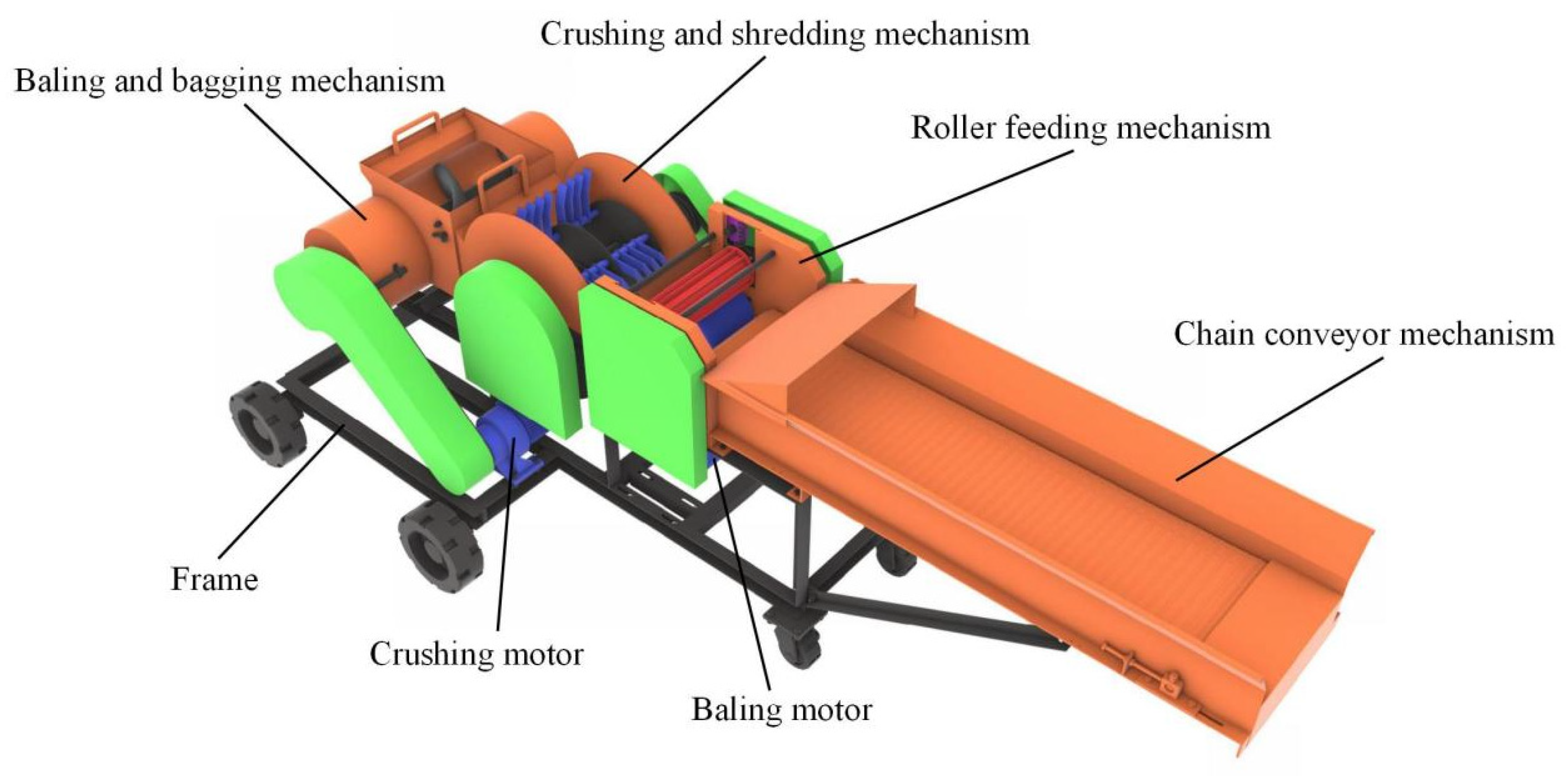
2.1. Overall Structure

Based on the requirements for silage feed processing and storage, the overall structure of the machine is shown in Figure 1. The machine primarily comprises a chain conveyor mechanism, a roller feeding mechanism, a crushing and shredding mechanism, a baling and bagging mechanism, a frame, a crushing motor, and a baling motor. The coordinated operation of these components ensures the functionality of the entire system.

2.2. Working Principle

During operation, whole green maize is manually transported to the chain conveyor mechanism and fed into the roller feeding mechanism. The flattening roller moves up and down based on the amount of straw being fed, automatically adjusting the feed opening to ensure continuous and uniform feeding. The wire-stripping roller and flattening roller clamp the silage straw, ensuring consistent lengths of material as it enters the crushing and shredding mechanism. At this stage, the material undergoes breaking, wire-stripping, and flattening.
The silage feed is then transported into the crushing and shredding chamber, where high-speed rotating serrated curved hammer blades, along with inner wall nails and jaw tooth plates, chop, collide with, tear, compress, and repeatedly rub the material, shredding it into a filamentous form. Filamentous material of the appropriate length is propelled into the baling and bagging mechanism via airflow and the centrifugal force generated by the high-speed rotor.
Within the baling mechanism, the material is further conveyed by a helical blade. The combined effects of the blade’s thrust, external forces at the cylinder’s end, friction from the inner wall, and counterforces from the cylinder wall compact the material, compressing it into cylindrical bales. The bales, with a diameter of 300 mm and a width of 500 mm, are discharged from the outlet. Finally, the bales are manually bagged and sealed in silage bags for storage, completing the integrated filling process.

2.3. Transmission System

The machine employs two independent power transmission systems, each driven by its own electric motor. The shredding motor drives the chain conveyor mechanism, roller feeding mechanism, and the crushing and shredding mechanism, while the baling motor powers the baling and bagging mechanism. The entire transmission consists of pulleys, gears, sprockets, shafts, and fasteners. The transmission modes include belt, gear, and chain transmissions, as shown in Figure 2. The shredding motor setup utilized a three-phase asynchronous motor (Model: YE132S-4, Manufacturer: Lanzhou Tezhong Electromechanical Equipment Co., Ltd., Lanzhou, China), which provided a rated power of 5.5 kW and a rotational speed of 1440 rpm. The baling motor is a three-phase asynchronous motor (Model: YE3-132M-6, Manufacturer: Fangli Holdings Co., Ltd., Shenzhen, China), which provided a rated power of 5.5 kW and a rotational speed of 964 rpm.

2.4. Main Mechanism Designs and Force Analyses

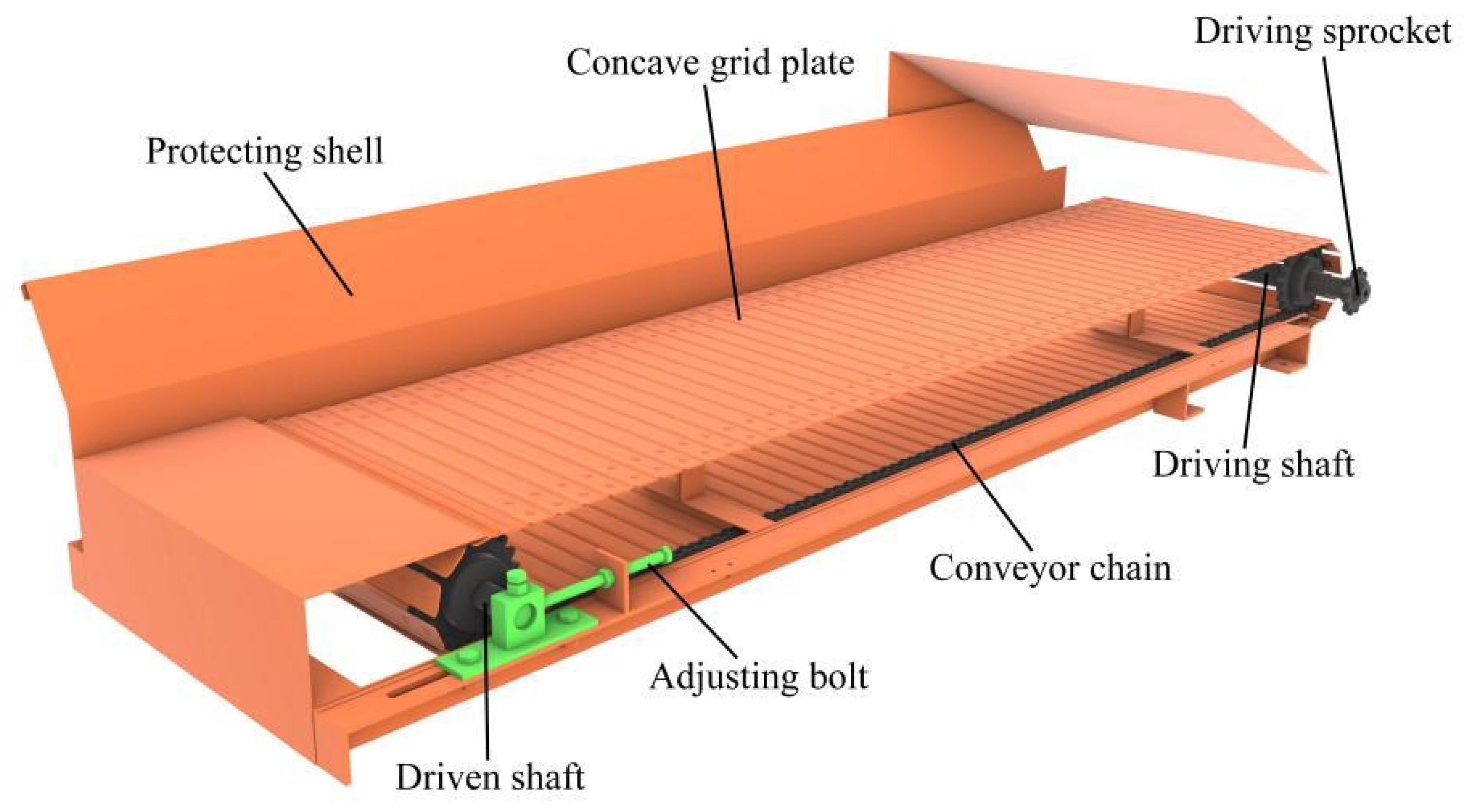
2.4.1. Straw Conveying Mechanism

The chain conveyor mechanism consists of a concave grate plate, a driving sprocket, a driving shaft, conveyor chains, positioning bolts, a driven shaft, and protective plates (as shown in Figure 3). The mechanism is based on two perforated side-plate conveyor chains, with the concave grate plate riveted onto the chains. Positioning bolts are used to limit the displacement of the driven shaft and achieve tensioning, ensuring uniform and orderly straw conveyance. To ensure safety in terms of conveying distance and feed volume, the transmission components employ a specially designed double-side-plate perforated 12A-1 roller chain. The conveying distance is designed to be 1000 mm, with a concave grate plate length of 260 mm and a spacing of 200 mm between the two conveyor chains [21].
Considering the designed production capacity and feed inlet of the machine, along with the physical characteristics and slip rate of the silage, the conveyor chain speed is set at 0.6 m/s. The main shaft speed of the conveyor chain is then calculated using the following formula [22]:
n L = 60 × 1000 v L π d L
where n L is the rotational speed of the conveyor chain’s main shaft in rpm; vL represents the conveyor chain speed in m/s; and dL represents the revolving diameter of the conveyor chain in mm. The meanings of the symbols used in this article are provided in the Appendix A, and the same applies hereafter.
According to the assembly relationship, the rotation diameter of the conveyor chain should be larger than the pitch circle diameter of the driving sprocket, with a measured value of dL = 140 mm. Substituting into the calculation, the main shaft rotational speed of the conveyor chain is 82 rpm.

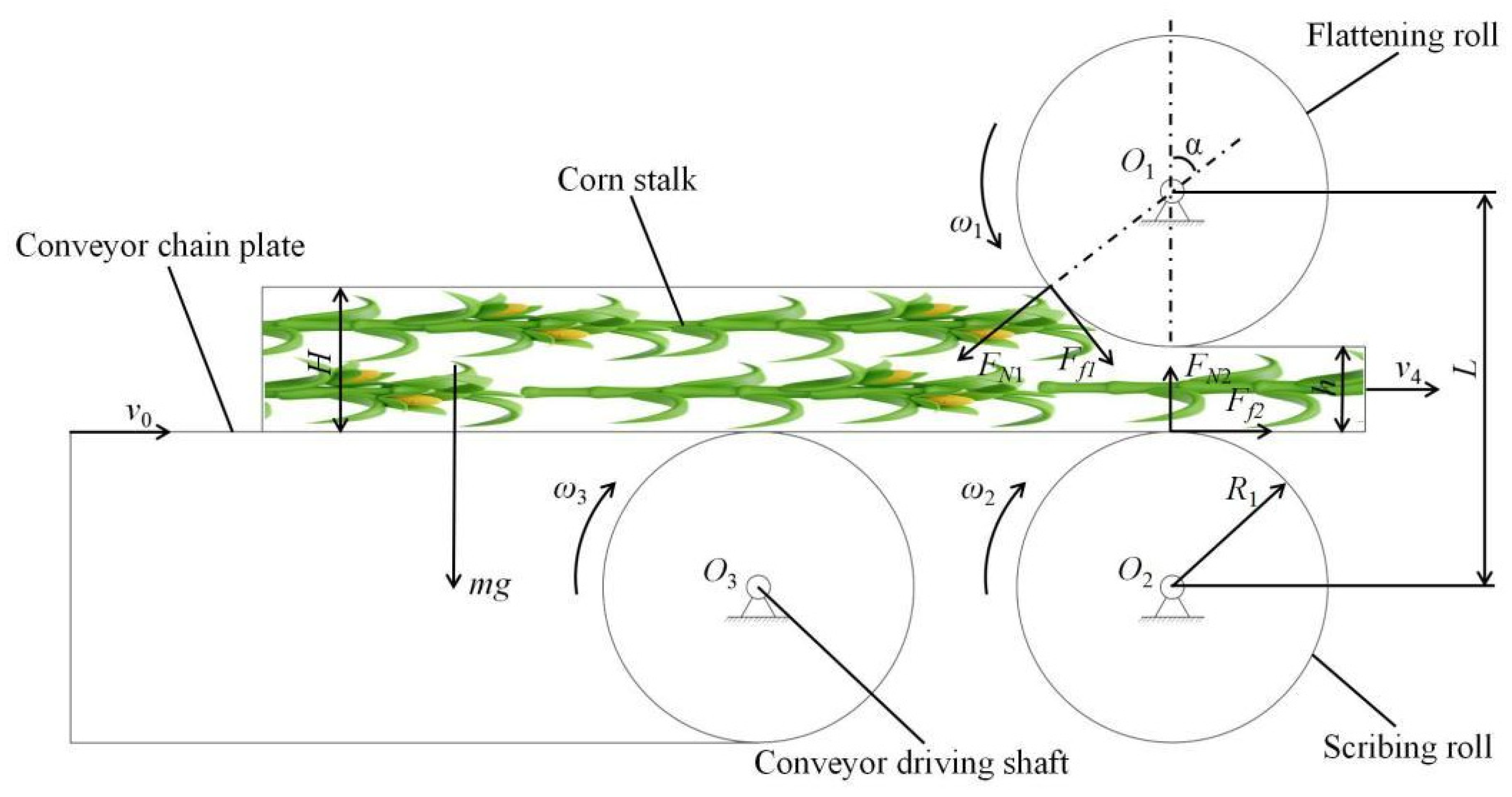
2.4.2. Straw Roller Feeding Mechanism

The straw feeding process is a critical component of the straw crushing and kneading machine. Its stability and continuity directly affect the efficiency of subsequent operations, including crushing, kneading quality, and baling density. The roller feeding mechanism primarily consists of a guard plate, a flattening roller, a spring, a scribing roller, a pulley, the main shaft of the conveying mechanism, a driving gear, and a driven gear (see Figure 4). During operation, the flattening and scribing rollers rotate in opposite directions at different speeds. The linear speed of the flattening roller is 1.2 times that of the scribing roller, enabling the effective grabbing, flattening, and scribing of straw.
The flattening roller features a floating spring design, allowing it to automatically adjust the feeding port opening based on the amount of straw fed. This ensures continuous and uniform feeding, precise chopping lengths, and reduced feed blockages.
The roller feeding mechanism measures 300 mm in length, 350 mm in width, and 360 mm in height, with a feeding port measuring 260 mm wide and 140 mm high. Both the flattening and scribing rollers are 280 mm long, with diameters of 120 mm. The scribing roller rotates at 120 r/min, while the flattening roller rotates at 143 r/min.
The flattening roller is a smooth cylindrical roller modified to have a 5 mm diameter, with 280 mm long round steel rods evenly distributed along its tangential direction, creating a deep-groove roller with excellent gripping and flattening capabilities. Similarly, the scribing roller is a smooth cylindrical roller modified with 5 mm high and 5 mm wide saw teeth evenly distributed circumferentially, providing excellent scribing ability [23].
To ensure the smooth feeding of straw, the frictional force generated by the rotation of the flattening roller and the scribing roller on the corn straw must exceed the horizontal component of the normal force [24,25]. Both rollers are made of the same material, and the friction coefficient between the straw and the rollers is identical. Figure 5 illustrates the force and motion analysis of the feeding process, where the friction forces and normal forces are calculated with the following formulae:
F f 1 cos α + F f 2 F N 1 sin α 0 F N 2 = F N 1 cos α + F f 1 + m g F f 1 = μ 1 F N 1 F f 2 = μ 1 F N 2 μ 1 = tan β
In Equation (2), μ1 represents the friction coefficient between the straw and the flattening roller and scoring roller; α represents the angle between the normal force and the vertical direction (degree); β represents the angle of friction for straw (degree); FN1 represents the normal force exerted by the flattening roller on the straw (N); FN2 represents the support force exerted by the scoring roller on the straw (N); Ff1 represents the friction force exerted by the flattening roller on the straw (N); Ff2 represents the friction force exerted by the scoring roller on the straw (N); m represents the mass of the straw (kg); and g represents gravitational acceleration (m/s2).
According to Equation (2), when 2tanβ ≥ tanα, the friction angle β of the straw generally ranges from 17° to 27°, the angle α ranges from 32° to 46°, ensuring that the flattening roller can smoothly complete the feeding process [26].
The radii of the flattening roller and scoring roller satisfy the following equations:
L = 2 R 1 + h = R 1 1 + cos α + H R 1 H h 1 cos α
where R1 represents the radius of the flattening roller and scoring roller (mm); H represents the thickness of the fed straw flow (mm); h represents the gap between the flattening roller and the scoring roller (mm); and L represents the center distance between the two rollers (mm).

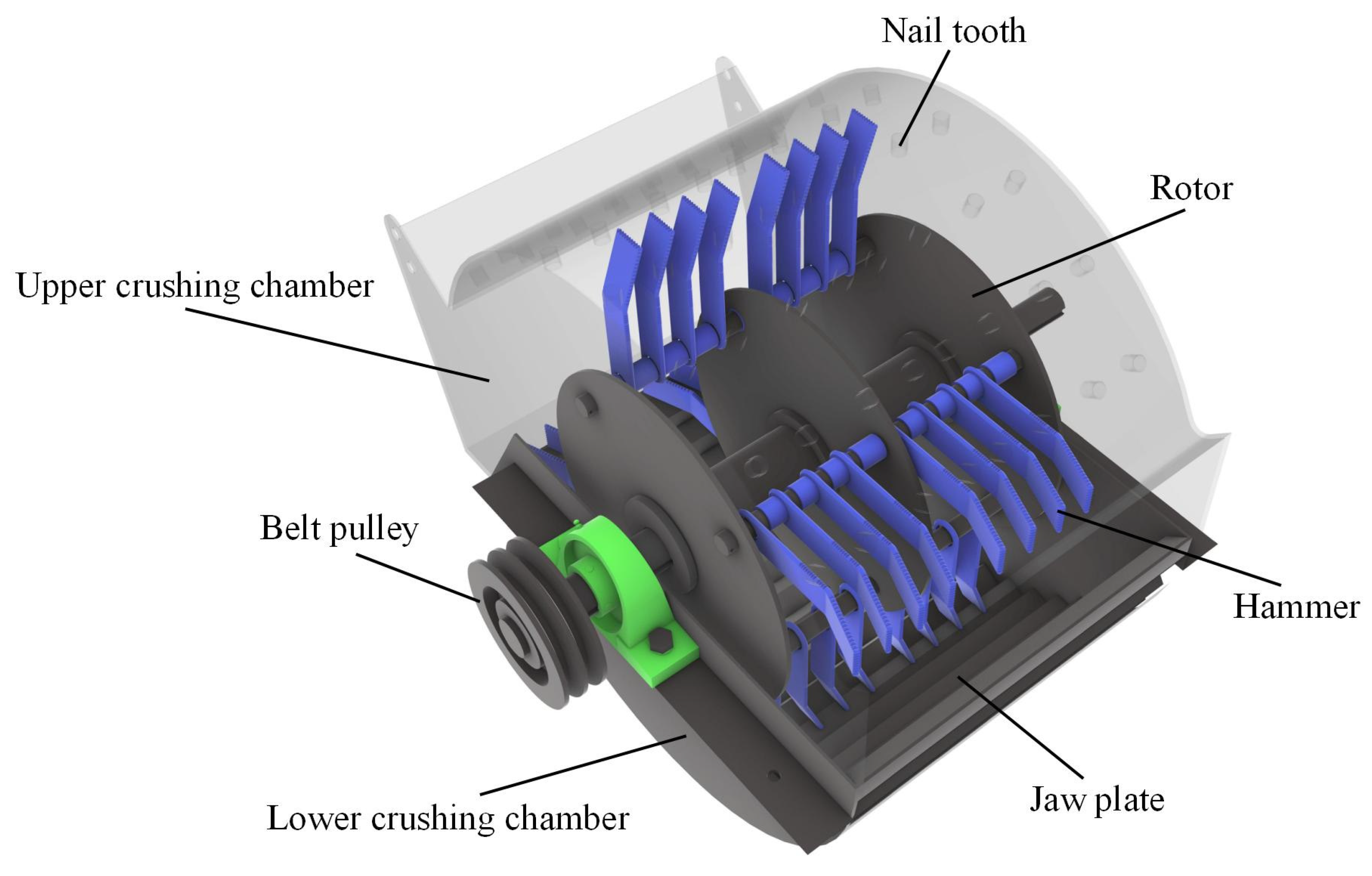
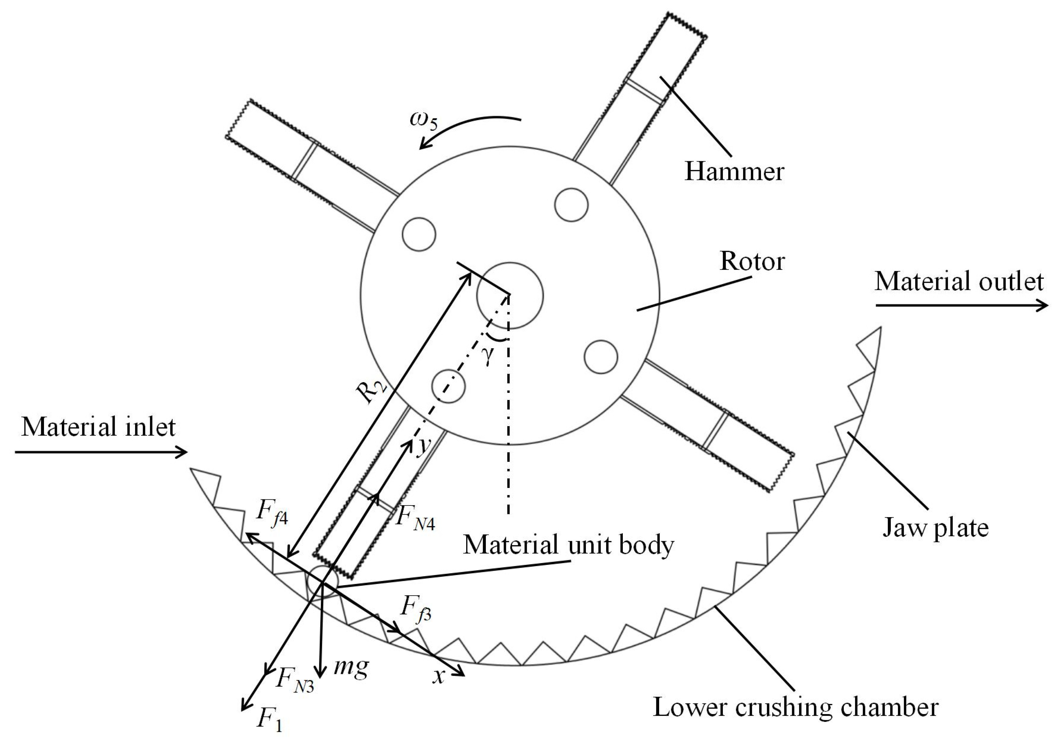
2.4.3. Straw Crushing and Kneading Mechanism

The crushing and kneading mechanism is a key component of silage processing machinery, as the straw processing primarily occurs during this stage, directly affecting the processing quality [27,28]. This mechanism mainly consists of the upper crushing chamber, nail teeth, rotor, curved hammer blades, jaw plate, and lower crushing chamber (as shown in Figure 6). When straw enters the crushing chamber, it is acted upon by high-speed rotating curved hammer blades. Under the combined action of these blades, the jaw plate, and the nail teeth, the straw is repeatedly chopped, torn, compressed, and kneaded until it is crushed into fine material and ejected from the chamber [29].
The machine is designed with nail teeth and a jaw plate installed in the upper and lower kneading chambers, respectively. This arrangement alters the motion path of the straw within the kneading chamber, increasing its fluctuations and the number of impacts, thereby enhancing the fiberization effect.
The machine is equipped with serrated curved hammer blades made of 65Mn steel. These blades cover more crushing and kneading space during operation, increasing the contact area between the straw and the blades, which improves the kneading quality and striking density [30]. The hammer blades are arranged in a symmetrical, staggered pattern, with a total of 32 blades. Each blade has a thickness of 4 mm and a width of 50 mm.
The rotor of the machine has a diameter of 230 mm and a width of 290 mm, with a maximum rotational diameter of 470 mm. The nail teeth have a maximum height of 24 mm, while the jaw plate has a maximum height of 23 mm.
Figure 7 illustrates the force and motion analysis of the straw crushing and kneading process, based on the hammering and kneading forces observed during straw fiberization. At the moment of straw kneading and crushing, the following conditions are satisfied [31,32]:
F x = F f 3 + m g sin γ F f 4 = 0 F y = F 1 + F N 3 + m g cos γ F N 4 = 0
F 1 = m ω 5 2 R 2
F f 3 = μ 2 F N 3
F f 4 = μ 3 F N 4
where ω5 is the angular velocity of the hammer blade (rad/s); γ is the angle between the line connecting the straw section and the rotor spindle axis and the vertical direction (degree); F1 represents the centrifugal force of the straw segment (N); FN3 represents the support force of the hammer blade on the straw segment (N); FN4 represents the support force of the lower kneading chamber on the straw segment (N); Ff3 represents the frictional force of the hammer blade on the straw segment (N); Ff4 represents the frictional force of the lower kneading chamber on the straw segment (N); R2 represents the rotational radius of the straw segment (mm); μ2 represents the friction coefficient between the straw segment and the hammer blade; and μ3 represents the friction coefficient between the straw segment and the lower kneading chamber.

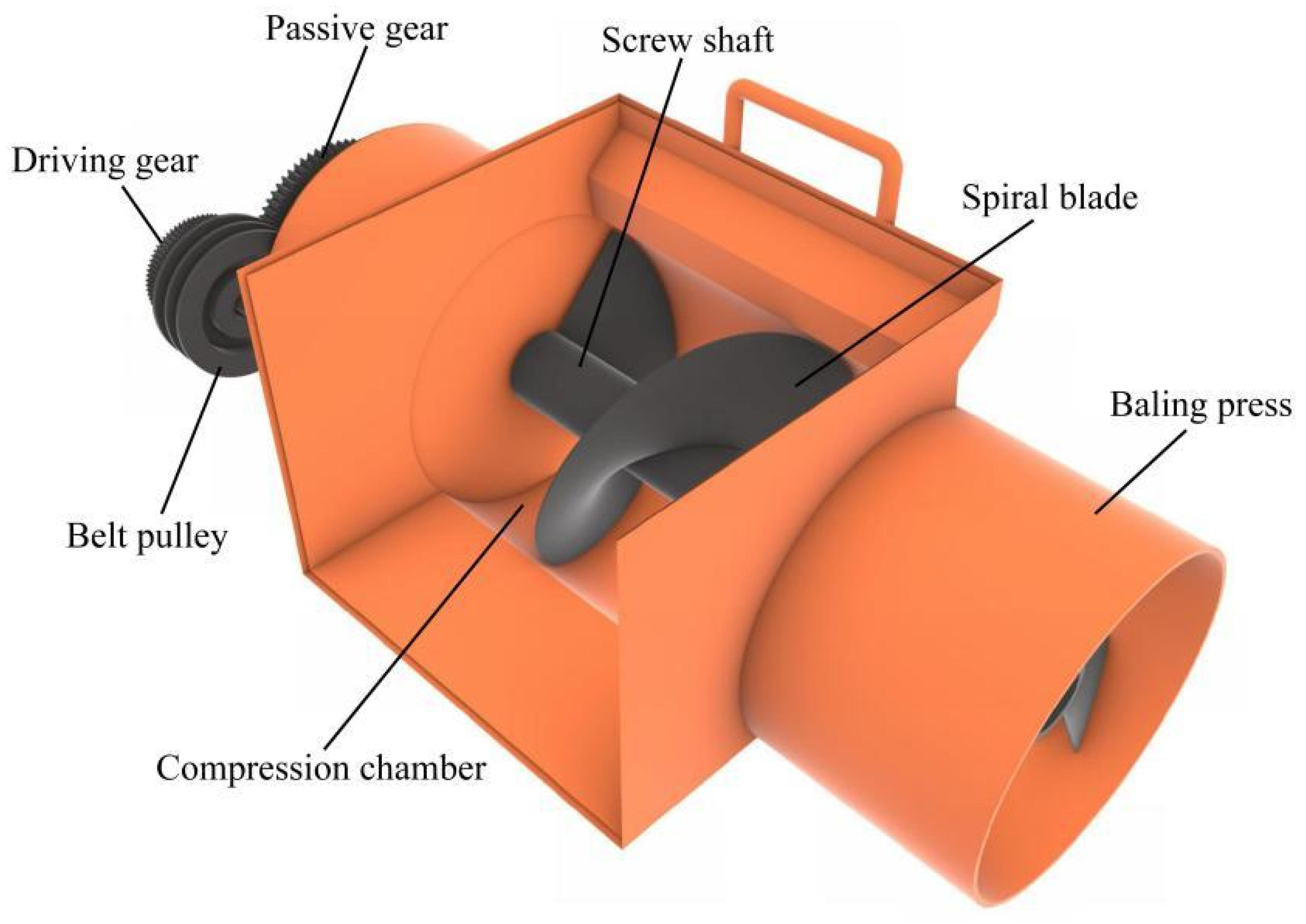
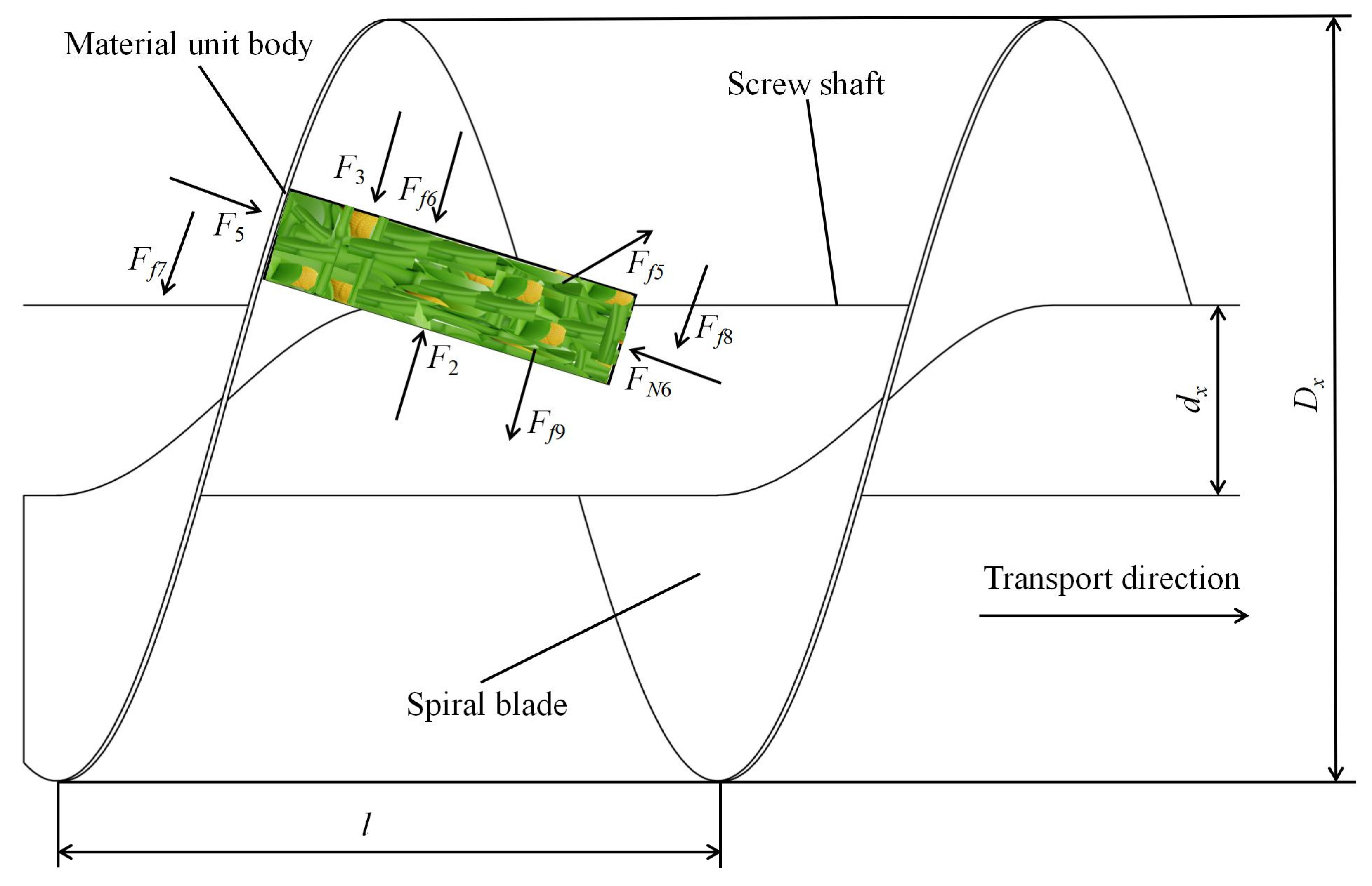
2.4.4. Straw Baling and Bagging Mechanism

The baling and bagging mechanism is based on a screw conveyor, designed with a compression chamber without spiral blades and a circular baling cylinder for manual bagging [33,34]. The mechanism mainly includes a screw shaft, spiral blades, pulleys, a baling cylinder, and a compression chamber (as shown in Figure 8). During operation, shredded straw material is fed into the screw conveyor, where the baling motor drives the spiral blades to rotate, moving the material slowly toward the outlet. As material accumulates between the blades, it starts to pile up, and when the material inside the wall reaches a certain weight, the friction force of the inner wall increases, causing the compression density to gradually increase from the outlet to the screw’s end. Simultaneously, as the screw shaft rotates, the phase angle of the spiral blades changes, causing the blades to grip the material and move it past the feed inlet into the baling cylinder. The material is compressed and transported by the pressure exerted by the blades, the main shaft, and the inner wall. As the spiral rotates, the material is conveyed into the compression chamber at the end of the spiral blades. In the compression chamber, the material accumulates and takes shape. When the accumulation reaches a certain quantity, it is subjected to the combined action of external force, thrust from the end of the spiral, and friction from the cylinder’s inner wall. The material is compressed into cylindrical bales [35], extruded from the molding outlet, and manually bagged, sealed, and packed into silage bags, completing the integrated bagging process for silage feed.
The force analysis of the infinitesimal volume of shredded straw material is shown in Figure 9, and it satisfies the following relationship [36]:
F 2 = P l d h
F 3 = P + P z d z l d h
F f 5 = f 1 P l d z + ρ d z l d h a n
F f 6 = f 3 P l d z
F N 5 = P d h d z + F 4
F f 1 = f 2 P d h d z + F 4
F N 6 = P d h d z
F f 8 = f 2 P d h d z
F f 9 = f 3 P l d z
F 4 = F N 5 F N 6
where F2 represents the pushing force exerted on the infinitesimal volume by the following material (N); F3 represents the resistance exerted on the infinitesimal unit by the material ahead (N); Ff5 represents the frictional force on the surface of the baling cylinder (N); Ff6 represents the frictional force of the material above the infinitesimal element (N); FN5 represents the normal pressure on the pressure surface of the spiral blade (N); Ff7 represents the frictional force on the bearing surface of the spiral blade (N); FN6 represents the normal pressure on the back surface of the spiral blade (N); Ff8 represents the frictional force on the reverse side of the spiral blade (N); Ff9 represents the frictional force of the material below the infinitesimal element (N); F4 represents the normal pushing force exerted on the infinitesimal unit by the advancing face (N); P represents the pressure acting on the infinitesimal element (Pa); h represents the height of the material (mm); z represents the transportation length of the material (mm); ρ represents the density of the material (kg/m3); an represents the acceleration of the material (m/s2); f1 represents the friction coefficient between the material and the baling cylinder; f2 represents the friction coefficient between the material and the spiral blade and spiral shaft; and f3 represents the internal friction coefficient between the materials.
The baling drum of the machine is designed with an inner diameter of 300 mm, a compression chamber length of 600 mm, and a feeding port size of 310 mm in length and 220 mm in width. The conveying and compaction capabilities of the baling and bagging mechanism are primarily influenced by the rotational speed of the helical shaft, the pitch, and the diameter of the helical blade. The main parameter relationships satisfy the following [37]:
Q = 47 D x 2 λ l γ n x ε
D x φ Q λ ε ρ d 2.5
d x = 0.2 ~ 0.35 D x
n < n m a x = k D x
l = 0.5 ~ 2.2 D x
In the above equations, Dx represents the external diameter of the spiral blade (mm); dx represents the diameter of the spiral shaft (mm); l represents the screw pitch (mm); Q represents the conveying capacity (kg/h); nx represents the rotational speed of the spiral shaft (rpm); λ represents the filling coefficient, set to 0.4; γ represents the material characteristic coefficient [38]; ρ d represents the bulk density of the material (kg/m3); ε represents the inclined conveying coefficient, with a value of 1 for horizontal conveying; k represents the comprehensive characteristic coefficient of the material; φ represents the comprehensive characteristic coefficient of the silk-like corn stalks.
Silage density is a critical factor affecting nutrient retention, with a higher compaction density significantly reducing losses in bagged storage [39]. To further determine the feasibility of the bale packaging mechanism and to verify the quality of the screw conveyor in transporting shredded straw material and compacting it into a bale, a simulation of the bale packaging process was carried out using the discrete element method (DEM), providing a theoretical basis for parameters such as the screw conveyor rotation speed and feeding rate.
The shredded corn stalks have complex and diverse shapes. To reduce the complexity of the simulation calculations, the shapes and sizes of shredded corn stalks were simplified as shown in Figure 10. In the discrete element software EDEM 2022.3 (Altair Engineering Inc., Troy, MI, USA), the actual material of 12.5 mm × 2.0 mm × 2.0 mm [40] with a moisture content of 60% was selected. The bale packaging unit was modeled using SolidWorks 2022 (Dassault Systèmes, Vélizy-Villacoublay, France), then it was simplified and converted to STEP format to be imported into EDEM software. The simulation time was set to 6 s, with the feeding rate of shredded material matching the machine’s production capacity of 2500 kg/h. The time step for the DEM simulations was set to 4.12 × 10⁻⁶ s, which is approximately 20% of the Rayleigh time step, ensuring numerical stability while maintaining computational efficiency. The particle generation rate was calculated as 0.694 kg/s, and the initial velocity of particles entering the bale packaging mechanism was set to 5 m/s. The rotational speed of the screw shaft was 228 r/min. The Hertz–Mindlin no-slip contact model was used for the simulation particles, and the material property and contact parameters are listed in Table 1 and Table 2 [40,41]. To accurately capture the behavior of granular materials, rolling friction was incorporated into the model using the Standard Rolling Friction model in EDEM. This model is based on a linear rolling resistance formulation, where the rolling friction torque T r is calculated as follows [42]:
T r = μ r R r F r ω r
where μ r is the coefficient of rolling friction, R r is the particle radius (mm), F r is the normal force (N), and ω r is the unit angular velocity vector of the object at the contact point.
The DEM simulations were carried out on a workstation equipped with 32 CPU cores and 32 GB of memory. The total simulation time reached approximately 96 h, underscoring the computationally intensive nature of DEM. To validate the accuracy of the discrete element simulation model for silk-like straw materials, this study conducted both simulation and physical experiments using the cylinder lifting method to measure the angle of repose. The experiments were repeated five times, with the average angle of repose from the simulation being 36.63° and from the physical test being 35.19°, resulting in a relative error of 4.09%. These results demonstrate that the discrete element model for filamentous straw materials is highly accurate and reliable, effectively simulating the mechanical behavior of the actual material.

2.5. Equipment Performance Test Design

To verify the working performance of the canning-type silage feed crushing, raking, and bundling integrated machine and determine the optimal working parameter combination, performance tests were conducted at the Engineering Training Center of Gansu Agricultural University. The test conditions are shown in Figure 11. The test material comprised whole maize stalks placed in their natural state for about 15 days after harvesting and bundling. The average length of the stalks was 2400 mm, with an average moisture content of 60%. The root diameter ranged from 15 to 36 mm, the middle diameter from 10 to 29 mm, and the top diameter from 5 to 12 mm. The maximum diameter of the maize ears was 60 mm. The test instruments included silage bags, tape measures, vernier calipers, stopwatches, and electronic scales.
Based on the “NY/T 509-2015 Technical Specifications for Quality Evaluation of Straw Raking Machines” and “DG/T 053-2019 Hay Shredding Machines” [43,44], productivity Y1 and raking rate Y2 were chosen as evaluation indices. A three-factor, three-level experiment was designed using Box–Behnken central composite design theory, with the number of hammer blades X1, hammer blade length X2, and hammer head tilt angle X3 as the experimental factors. The factor coding is shown in Table 3.
The calculation of productivity Y1 is shown as follows:
Y 1 = S T
where S represents the amount of material processes during the operation time (kg) and T represents the duration of the operation (h).
The filamentation rate Y2 is calculated using the following formula:
Y 2 = W a W b × 100 %
where Wa represents the mass of filamented straw in the sample (g) and Wb represents the mass of the sample (g).

3. Results and Discussion

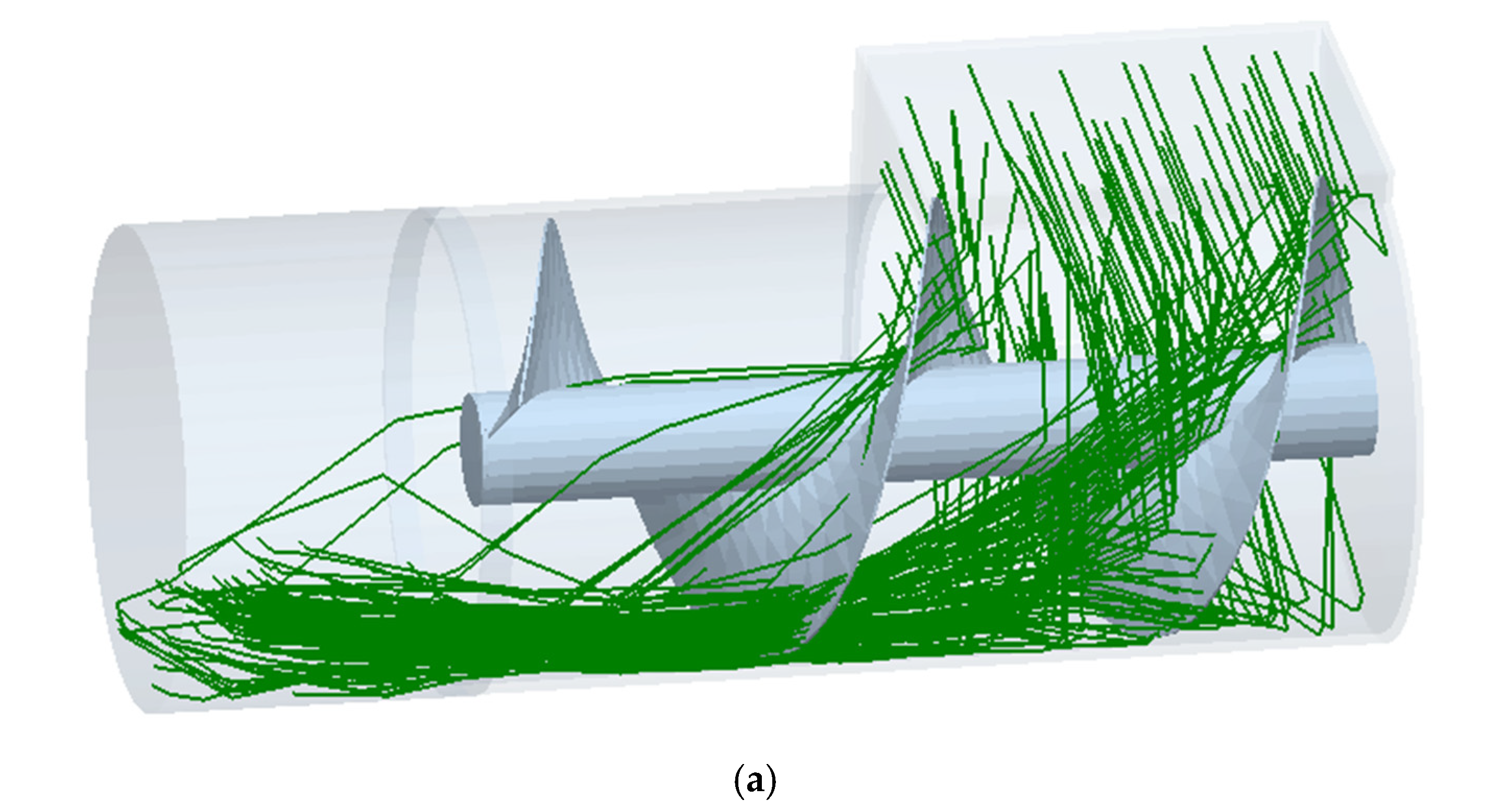
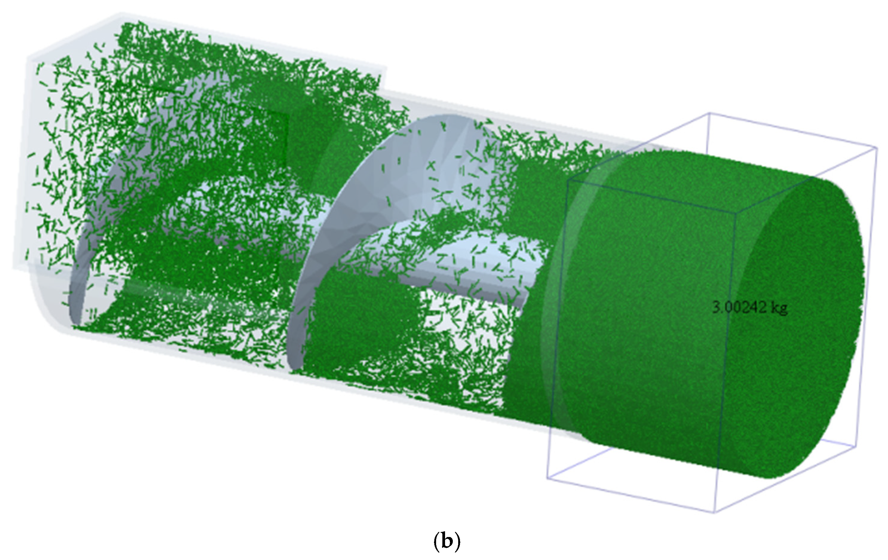
3.1. Simulation Process of Bale Packaging and Results Analysis

To evaluate the compaction and forming effect of the silaged material, the Setup Selections function in the post-processing module of EDEM software was utilized to create a Grid Bin Group monitoring area. The actual mass of the compacted silage material within the model was monitored, and the data were extracted and converted to density to determine the density of the formed bale. The test results were compared with the “DG/T 043-2024 Baler” standard [45].
The density of the bale is calculated as
m d = m q 1 G 1 0.2 V q = 1 4 π d q 2 h q ρ q = m d V q
where md represents the equivalent mass of the bale (kg); mq represents the actual measured mass of the bale (kg); G represents the moisture content of the straw (%); ρq represents the compaction density of the bale (kg/m3); Vq represents the volume of the bale (m3); dq represents the diameter of the silage bag (mm); and hq represents the height of the silage bag (mm).
The simulation process of baling and bagging filamentous straw materials is illustrated in Figure 12. Figure 12a shows the linear flow of particles at 2 s, where initial particle accumulation in the silage bag is observed. Figure 12b shows the bale formation at 6 s of the simulation. According to the DEM simulation, the actual mass of the bale in the monitoring area reaches 3.00242 kg. By substituting into Equation (26), the bale density is calculated as 140.067 kg/m3. The bale density meets operational requirements, demonstrating that the mechanism can compress filamentous straw into cylindrical bales, successfully completing the baling process.

3.2. Equipment Performance Test

3.2.1. Results and Analysis

The test results for straw productivity Y1 and the filamentation rate Y2 are presented in Table 4.
The data in Table 4 were analyzed using quadratic regression equations and linear fitting to obtain the quadratic polynomial regression model for productivity Y1 and silking rate Y2 concerning the hammer quantity X1, hammer blade length X2, and hammerhead inclination angle X3. Significance tests and variance analysis were conducted on the test factors to further identify the key factors affecting performance. The variance analysis results for productivity Y1 and silking rate Y2 are shown in Table 5.
As shown in Table 5, the regression model for productivity Y1 is extremely significant. The coefficient of determination R2 is 0.9247, indicating that the regression model can explain 92.47% of the response value variation. The lack-of-fit term is not significant, suggesting small experimental error and good fitting of the regression equation. X1, X2, X1X2, X22, and X32 have extremely significant effects on productivity Y1. X3, X1X3, and X2X3 have significant effects, while other factors have no significant effects. The order of influence of the test factors on productivity Y1 is hammer quantity X1, hammer blade length X2, and hammerhead inclination angle X3. After excluding insignificant terms without losing fit, the final multivariate quadratic regression equation for productivity Y1 is obtained, as follows:
Y 1 = 2686.55 + 99.36 X 1 + 98.44 X 2 + 43.06 X 3 + 83.54 X 1 X 2 51.30 X 1 2 98.51 X 2 2 102.75 X 3 2
From Table 5, it can be concluded that the regression model for the fiberization rate Y2 is highly significant; the R2 value of the model is 0.8458, indicating that the regression model can account for 84.58% of the variation in the response variable. The lack of fit is not significant, indicating small experimental errors and a good fitting of the regression equation. X2, X1, and X32 significantly affect Y2, while X3, X22, and X1X3 have a significant effect. Other factors do not significantly influence the fiberization rate. The order of influence on Y2 is hammer blade length X2, hammer number X1, and hammer head tilt angle X3. After eliminating the insignificant terms, the final multiple quadratic regression equation for Y2 is as follows:
Y 2 = 92.28 + 0.99 X 1 + 1.72 X 2 + 0.83 X 3 0.92 X 1 X 3 1.20 X 2 2 1.10 X 3 2

3.2.2. Parameter Optimization and Experimental Verification

To achieve the optimal parameter combination for the best operational performance, the multi-objective optimization algorithm in Design-Expert 10 (Stat-Ease Inc., Minneapolis, MN, USA) was employed. The optimization objectives were to maximize machine throughput and the straw fiberization rate. A mathematical model for optimization was established through analysis, identifying the optimal working parameters for the canning-style silage feed crushing, fiberization, and bundling machine as follows: 31.45 hammer blades, a hammer blade length of 99.16 mm, and a hammer head tilt angle of 14.12°. With these parameters, the machine achieved a throughput of 2806.05 kg/h and a fiberization rate of 93.62%.
To verify the reliability of the optimization results, the hammer blade number was adjusted to 32, the hammer blade length was rounded to 99 mm, and the hammer head tilt angle was rounded to 14°. The optimization results were validated through tests repeated five times. The average value of the five test results was taken as the actual value for the evaluation indicators under these conditions.
The compacted density of the straw bundles is primarily influenced by the friction coefficient of the compression chamber’s inner wall and the compression chamber length. For testing, the machine was configured with an inner wall friction coefficient of 0.5 and a compression chamber length of 600 mm. Performance tests were conducted based on the straw density testing method, with the results presented in Table 6.
The verification test results indicate that, under the optimized parameter combination, the test outcomes align closely with the optimization results, confirming the reliability of the optimization process. Both the productivity and fiberization rate meet practical work requirements, suggesting that the optimized parameters represent the best working conditions for the silage feed crushing, fiberization, and baling integrated machine. During testing, the machine operated smoothly without significant feed blockages or jamming, and the noise level complied with the required standards.

4. Conclusions

To address the issues of clogging, labor-intensive manual loading, and poor sealing in existing small-scale pulverizing and fiberizing machines and balers used in hilly areas and small-scale planting regions, a canned silage feed crushing, fiberizing, and baling integrated machine was developed. This machine combines the functions of crushing, fiberizing, and baling into a single system.
The process begins with silage feed being transported and broken down by a chain conveyor and roll feeding mechanism. The feed is then flattened and fiberized in a pulverizing and fiberizing chamber before being compressed and bagged into silage bags by the baling mechanism. This integration improves the filling efficiency and automates the entire process.
Key components of the machine were systematically designed. Force and motion analyses were conducted for the feeding, fiberizing, and compression processes, leading to the determination of the structure and working parameters for the chain conveyor, roll feeding mechanism, pulverizing and fiberizing mechanism, and baling mechanism. Simulation tests of straw material compression and bagging showed that after six seconds of operation, the bale density reached 140.067 kg/m3, meeting the requirements for integrated filling operations.
Experimental tests were conducted to evaluate factors such as the number of hammers, hammer blade length, and hammer head angle, using productivity and fiberization rate as performance indicators. Variance analysis revealed the following influences:
For productivity, the number of hammers had the greatest impact, followed by hammer blade length and hammer head angle.
For the fiberization rate, hammer blade length was the most influential, followed by the number of hammers and hammer head angle.
The optimal parameters were found to be 32 hammers, a hammer blade length of 99 mm, and a hammer head angle of 14°. Under these conditions, the machine achieved a productivity of 2815.29 kg/h, a fiberization rate of 94.28%, and a bale density of 124.52 kg/m3. The machine operated smoothly, delivering high fiberization quality with no feed blockages, successfully meeting practical operational requirements.

Author Contributions

Methodology, T.D., W.S. and D.Z.; investigation, T.D., W.S. and D.Z.; software, T.D. and W.S.; formal analysis, T.D. and D.Z.; resources, W.S.; writing—original draft, T.D.; writing—review and editing, W.S. and P.A.S.; funding acquisition, W.S. All authors have read and agreed to the published version of the manuscript.

Funding

This research was funded by the Gansu Provincial University Industry Support Plan, grant number 2022CYZC-42 and the Gansu Provincial Department of Agriculture and Rural Affairs-Agricultural Machinery Equipment Research and Development Project, grant number njyf2024-03-1.

Data Availability Statement

The original contributions presented in the study are included in the article; further inquiries can be directed to the corresponding author.

Acknowledgments

The authors would like to thank Petru A. Simionescu from the Department of Mechanical Engineering, College of Engineering, Texas A&M University, for his valuable reviewing and editing of the paper.

Conflicts of Interest

The author declares no conflicts of interest.

Appendix A

Table A1. List of mathematical symbols.
SymbolDefinition DescriptionUnit
F1Centrifugal force of the straw segmentN
F2Pushing force exerted on the infinitesimal volume by the following materialN
F3Resistance exerted on the infinitesimal unit by the material aheadN
F4Normal pushing force exerted on the infinitesimal unit by the advancing faceN
F r Normal forceN
FN1Normal force exerted by the flattening roller on the strawN
FN2Support force exerted by the scoring roller on the strawN
FN3Support force of the hammer blade on the straw segmentN
FN4Support force of the lower kneading chamber on the straw segmentN
FN5Normal pressure on the pressure surface of the spiral bladeN
FN6Normal pressure on the back surface of the spiral bladeN
Ff1Friction force exerted by the flattening roller on the strawN
Ff2Friction force exerted by the scoring roller on the strawN
Ff3Frictional force of the hammer blade on the straw segmentN
Ff4Frictional force of the lower kneading chamber on the straw segmentN
Ff5Frictional force on the surface of the baling cylinderN
Ff6Frictional force of the material above the infinitesimal elementN
Ff7Frictional force on the bearing surface of the spiral bladeN
Ff8Frictional force on the reverse side of the spiral bladeN
Ff9Frictional force of the material below the infinitesimal elementN
αAngle between the normal force and the vertical directiondegree
βAngle of friction for strawdegree
γAngle between the line connecting the straw section and the rotor spindle axis and the vertical directiondegree
vLConveyor chain speedm/s
nLRotational speed of the conveyor chain’s main shaftrpm
nxRotational speed of the spiral shaftrpm
ω5Angular velocity of the hammer bladerad/s
dLRevolving diameter of the conveyor chainmm
HThickness of the fed straw flowmm
hGap between the flattening roller and scoring rollermm
LCenter distance between the two rollersmm
R1Radius of the flattening roller and scoring rollermm
R2Rotational radius of the straw segmentmm
R r Particle radiusmm
hHeight of the materialmm
zTransportation length of the materialmm
DxExternal diameter of the spiral blademm
dxDiameter of the spiral shaftmm
lScrew pitchmm
dqDiameter of the silage bagmm
hqHeight of the silage bagmm
mMass of the strawkg
mdEquivalent mass of the balekg
mqActual measured mass of the balekg
SAmount of material processeskg
WaMass of filamented straw in the sampleg
WbMass of the sampleg
ρ Density of the materialkg/m3
ρ d Bulk density of the materialkg/m3
ρ qCompaction density of the balekg/m3
T r Rolling friction torqueN·m
PPressure acting on the infinitesimal elementPa
gGravitational accelerationm/s2
anAcceleration of the materialm/s2
QConveying capacitykg/h
GMoisture content of the straw%
VqVolume of the balem3
TDuration of operationh
μ1Friction coefficient between the straw and the flattening roller and scoring roller-
μ2Friction coefficient between the straw segment and the hammer blade-
μ3Friction coefficient between the straw segment and the lower kneading chamber-
μ r Coefficient of rolling friction
f1Friction coefficient between the material and the baling cylinder-
f2Friction coefficient between the material and the spiral blade and spiral shaft-
f3Internal friction coefficient between the materials-
λFilling coefficient-
εInclined conveying coefficient-
kComprehensive characteristic coefficient of the material-
φ Comprehensive characteristic coefficient of the silk-like corn stalks-
ω r Unit angular velocity vector of the object at the contact point-

References

  1. Tan, R.H. Research on Thermal Characteristics of Main Crop Straw in Northwest China. Master’s Thesis, Northwest Agricultural and Forestry University, Yangling, China, 2017. (In Chinese). [Google Scholar]
  2. Wang, Y. The current situation and suggestions for the utilization of crop straw resources in China. Agric. Mach. Using Maint. 2016, 44–45. (In Chinese) [Google Scholar]
  3. Ferraretto, L.F.; Shaver, R.D.; Luck, B.D. Silage review: Recent advances and future technologies for whole-plant and fractionated corn silage harvesting. J. Dairy Sci. 2018, 101, 3937–3951. [Google Scholar] [CrossRef] [PubMed]
  4. Wu, K.; Song, Y.P. Research progress analysis of crop stalk cutting theory and method. Trans. Chin. Soc. Agric. Mach. 2022, 53, 1–20. (In Chinese) [Google Scholar]
  5. John, D. Forage Harvesters. John Deere Official Website. Available online: https://www.deere.com/en/hay-forage/harvesting/self-propelled-forage-harvesters/ (accessed on 11 March 2025).
  6. Schweier, J.; Becker, G. New holland forage harvester’s productivity in short rotation coppice: Evaluation of field studies from a German perspective. Int. J. For. Eng. 2012, 23, 82–88. [Google Scholar] [CrossRef]
  7. Krzyżaniak, K.; Kowalik, I.; Rybacki, P. Evaluation of the Operating Parameters of Self-Propelled Forage Harvesters During Maize Silage Harvest. Agric. Eng. 2023, 27, 229–239. [Google Scholar] [CrossRef]
  8. Golovkov, A.; Boiko, A.; Chaava, M. Justification of the choice of the type of forage harvester for farms. E3S Web Conf. 2019, 126, 00053. [Google Scholar] [CrossRef]
  9. Zhang, W. 9RS-3 Straw Kneading Machine Design and Performance Test. Master’s Thesis, Shanxi Agricultural University, Jinzhong, China, 2016. (In Chinese). [Google Scholar]
  10. Zhao, Z.G. The Experimental Study on the Performance of 9R-40 Model Rubbing Crusher. Master’s Thesis, Inner Mongolia Agricultural University, Hohhot, China, 2011. (In Chinese). [Google Scholar]
  11. Song, X.F.; Zhang, F.W.; Dai, F.; Zhao, W.Y. Design and experiment of 9FH-40 type of corn straw kneading machine. J. Agric. Mech. Res. 2024, 46, 60–65. (In Chinese) [Google Scholar]
  12. Su, H.Y.; Dai, F.; Dai, Z.G.; Yang, G.J.; Shi, L.R.; Feng, Y.Z.; Zhang, F.W. Design and experiment on 9LRC-60 type vertical straw kneading machine. J. Gansu Agric. Univ. 2013, 48, 151–156. (In Chinese) [Google Scholar]
  13. Tang, Z.; Li, Y.M.; Cheng, C. Development of multi-functional combine harvester with grain harvesting and straw baling. Span. J. Agric. Res. 2017, 15, e0202. [Google Scholar] [CrossRef]
  14. Zhang, D.Z.; Sun, W.; Liu, X.L.; Zhang, H.; Zhang, R.; Zhang, W. Design and research of the combined cutting and kneading silage corn crusher. J. Chin. Agric. Mech. 2019, 40, 93–100. (In Chinese) [Google Scholar]
  15. You, H.; Wang, H.D.; Huan, X.L.; Wang, D.C.; Kang, C.C.; Ye, B.N. Design and experiment of roller crushing device of king grass harvester. Trans. Chin. Soc. Agric. Mach. 2021, 52, 134–142. (In Chinese) [Google Scholar]
  16. Tang, Z.; Zhang, B.; Liu, X.; Ren, H.; Li, X.Y.; Li, Y.M. Structural model and bundling capacity of crawler picking and baling machine for straw wasted in field. Comput. Electron. Agric. 2020, 175, 105622. [Google Scholar] [CrossRef]
  17. Zhao, Y.; Zhai, Z.; Gao, B.; Lan, Y. Numerical prediction and optimization of aerodynamic noise of straw crushers by considering the straw-crushing process. Phys. Fluids 2024, 36, 043330. [Google Scholar] [CrossRef]
  18. Hartati, S.; Musabbikhah, M.; Suryono, E. Multifunction hammer mill machine design and assembling to destroy an agricultural wastes. In Proceedings of the International Conference on Applied Science and Engineering (ICASE 2018), Sukoharjo, Indonesia, 6–7 October 2018; pp. 101–104. [Google Scholar]
  19. Zhang, J.; Feng, B.; Yu, X.Z.; Zhao, C.; Li, H.; Kan, Z. Experimental study on the crushing properties of corn stalks in square bales. Processes 2022, 10, 168. [Google Scholar] [CrossRef]
  20. Li, W.Q.; Lu, J.; Wang, Z.G.; Yu, Z. Forage bag silage technology. Feed Ind. 2019, 40, 58–61. (In Chinese) [Google Scholar]
  21. Chinese Academy of Agricultural Machinery Sciences. Agricultural Machinery Design Manual; China Agricultural Science and Technology Press: Beijing, China, 2007. (In Chinese) [Google Scholar]
  22. Du, J.Q.; Su, H.; Qian, S.Z.; De, X.H. Design optimization and performance evaluation of corn straw crushing and rubbing filament machine. BioResources 2024, 19, 2286. [Google Scholar] [CrossRef]
  23. Wang, Z.; Song, Z.H.; Liu, P.; Yan, Y.F.; Li, Y.; Ren, L.L.; Song, Y.P. Development and experiment of crop feeding angle parameter model in chopping roll of hay cutter. Trans. Chin. Soc. Agric. Mach. 2024, 55, 200–211. (In Chinese) [Google Scholar]
  24. Hahn, F.; Poblano, E.; Pérez, R.; Jenkins, T. Design and evaluation of geared rollers for a roselle harvester. Trans. ASABE 2016, 59, 777–785. [Google Scholar]
  25. Sun, N.N.; Wang, X.Y.; Li, H.W.; He, J.; Wang, Q.J.; Wang, J.; Liu, Z.D.; Wang, Y.B. Design and experiment of differential sawing rice straw chopper for turning to field. Trans. Chin. Soc. Agric. Eng. 2019, 35, 267–276. (In Chinese) [Google Scholar]
  26. Wang, T.J.; Wang, T.L.; Cui, H.G.; Gong, Y.J.; Tian, S.B.; Wang, R.L. Design and experiment of adjustable feeding straw bale-breaking and rubbing filament machine. Trans. Chin. Soc. Agric. Mach. 2021, 52, 148–158. (In Chinese) [Google Scholar]
  27. Chen, L.Q.; Zhang, J.Q.; Kong, X.L. Genetic optimal design of straw crusher based on ADAMS. Adv. Mater. Res. 2010, 139–141, 929–932. [Google Scholar] [CrossRef]
  28. Orisaleye, J.I.; Jekayinfa, S.O.; Ogundare, A.A.; Adefuye, O.A.; Bamido, E. Effect of screen size on particle size distribution and performance of a small-scale design for a combined chopping and milling machine. Clean. Eng. Technol. 2022, 7, 100426. [Google Scholar] [CrossRef]
  29. Zastempowski, M.; Bochat, A. Research issues in the process of cutting straw into pieces. Sustainability 2020, 12, 6167. [Google Scholar] [CrossRef]
  30. Jankauskas, V.; Abrutis, R.; Žunda, A. Wear and damage study of straw chopper knives in combine harvesters. Machines 2024, 12, 789. [Google Scholar] [CrossRef]
  31. Tian, H.Q.; Wang, H.Q.; Huang, T.; Wang, D.; Liu, F.; Han, B.S. Design of combination sieve for hammer feed mill to improve crushing performance. Trans. Chin. Soc. Agric. Eng. 2018, 34, 45–52. (In Chinese) [Google Scholar]
  32. Chen, T.; Yi, S.J.; Li, Y.F.; Tao, G.X.; Mao, X.; Qu, S.M. Design and test of cutting and crushing cooperative silk kneading machine. Trans. Chin. Soc. Agric. Mach. 2024, 55, 149–159. (In Chinese) [Google Scholar]
  33. Zhao, Y. Design and Research of Compression Baling Device for Silage Corn. Master’s Thesis, Yunnan Agricultural University, Kunming, China, 2022. (In Chinese). [Google Scholar]
  34. Ma, P.B.; Li, L.Q.; Wen, B.Q.; Xue, Y.H.; Kan, Z.; Li, J.B. Design and parameter optimization of spiral-dragon type straw chopping test rig. Int. J. Agric. Biol. Eng. 2020, 13, 47–56. [Google Scholar] [CrossRef]
  35. Li, L.Q.; Wang, D.F.; Yang, X. Study on round rice straw bale wrapping silage technology and facilities. Int. J. Agric. Biol. Eng. 2018, 11, 67–75. [Google Scholar] [CrossRef]
  36. Wang, W.Z.; Liu, W.R.; Yuan, L.H.; Qu, Z.; He, X.; Lu, Y.L. Simulation and experiment of single longitudinal axial material movement and establishment of wheat plants model. Trans. Chin. Soc. Agric. Mach. 2020, 51, 170–180. (In Chinese) [Google Scholar]
  37. Fan, Z.P. EDEM-based Screw Delivery Mechanism for Crushed Maize Straw. Master’s Thesis, Inner Mongolia Agricultural University, Hohhot, China, 2023. (In Chinese). [Google Scholar]
  38. Jia, C.B.; Cheng, H. Research on Parametric Study Method of Screw Conveyor. Mach. Des. Manuf. 2015, 4, 206–208+213. (In Chinese) [Google Scholar]
  39. Persson, T.; Bakken, A.K. A Review of the Effects of Density and Silo Type on Silage Fermentation, Nutritive Quality and Losses During Storage; NIBIO Rapport; NIBIO: Oslo, Norway, 2024. [Google Scholar]
  40. Song, X.F.; Dai, F.; Zhang, X.K.; Xie, J.H.; Yang, J.; Zhang, F.W. Numerical simulation and experiment of materials movement based on CFD-DEM coupling method in the discharging device of kneading machine. J. China Agric. Univ. 2017, 22, 99–107. (In Chinese) [Google Scholar]
  41. Zhang, R.Y. Research on the Compression Mechanism and Optimisation of Compression Processing Parameters of Chopped Corn Stalk Based on the Discrete Element Method. Master’s Thesis, Jilin University, Changchun, China, 2023. (In Chinese). [Google Scholar]
  42. DEM Solutions Ltd. EDEM User Manual; Version 2022.3; DEM Solutions Ltd.: Edinburgh, UK, 2022. [Google Scholar]
  43. NY/T 509-2015; Technical Specification for Quality Evaluation of Straw Ripping Machine. Ministry of Agriculture and Rural Affairs of the People’s Republic of China: Beijing, China, 2015. (In Chinese)
  44. DG/T 053-2019; Forage Crusher. Ministry of Agriculture and Rural Affairs of the People’s Republic of China: Beijing, China, 2019. (In Chinese)
  45. DG/T 043-2024; Baling (Pressing) Machine. Ministry of Agriculture and Rural Affairs of the People’s Republic of China: Beijing, China, 2024. (In Chinese)
Figure 1. CAD model of the crushing, shredding, and baling machine.
Machines 13 00228 g001
Figure 2. Transmission diagram of the machine.
Machines 13 00228 g002
Figure 3. CAD model of the chain conveyor.
Machines 13 00228 g003
Figure 4. Structure diagram of roller feeding mechanism.
Machines 13 00228 g004
Figure 5. Force and movement analysis during the straw feeding process.
Machines 13 00228 g005
Figure 6. Structure diagram of crushing and kneading mechanism.
Machines 13 00228 g006
Figure 7. Analysis diagram of force and movement of straw powder during kneading process.
Machines 13 00228 g007
Figure 8. CAD model of the baling and bagging mechanism.
Machines 13 00228 g008
Figure 9. Force analysis for an infinitesimal volume of shredded straw material inside the conveyor.
Machines 13 00228 g009
Figure 10. Silk-like fibrous DEM model of the corn stalks.
Machines 13 00228 g010
Figure 11. Performance testing of the crushing, shredding, and baling machine prototype.
Machines 13 00228 g011
Figure 12. Simulation process of baling and bagging mechanism. (a) Linear flow process of filamentous particles at 2 s of simulation time. (b) Hay bale formation at 6 s of simulation time.
Machines 13 00228 g012aMachines 13 00228 g012b
Table 1. Material property parameters.
AttributePoisson’s Ratio Shear Modulus/(Pa)Density/(kg/m3)
Stalk material0.41.1 × 107420
Baling and bagging device0.37 × 10107800
Table 2. Material contact parameters.
Contact FormRestitution CoefficientCoefficient of Static FrictionCoefficient of Rolling Friction
Stalk material—stalk material0.20.70.01
Stalk material—baling
and bagging device
0.20.40.01
Table 3. Test factors and levels.
Factor LevelTest Factor
Number of Hammers X1/(piece)Hammer Blade Length X2/(mm)Hammer Head Tilt Angle X3/(°)
−124500
0288015
13211025
Table 4. Test indicator results.
Test NumberX1X2X3Y1/(kg/h)Y2/%
1−1−102453.2188.92
21−102425.4891.10
3−1102489.9192.63
41102796.3492.98
5−10−12340.1688.16
610−12624.2292.35
7−1012398.3191.91
81012604.4591.67
90−1−12366.5387.32
1001−12532.4391.56
110−112320.6087.93
120112558.7491.65
130002664.5592.19
140002695.9491.28
150002739.2692.74
160002711.8293.28
170002643.6992.52
Table 5. Variance analysis.
IndicatorSource of VarianceSum of SquaresDegrees of FreedomMean SquareFp
Y1Model345,000938,311.6522.850.0002 ***
X174,821.22174,821.2244.620.0003 ***
X273,443.29173,443.2943.80.0003 ***
X317,632.69117,632.6910.520.0142 **
X1X227,915.73127,915.7316.650.0047 ***
X1X31517.8811517.880.910.3731
X2X31304.6511304.650.780.407
X1211,082.31111,082.316.610.037 **
X2240,862.78140,862.7824.370.0017 ***
X3292,181.88192,181.8854.970.0001 ***
Residual11,738.3171676.90
Lack of Fit6013.5832004.531.400.3651
Pure Error5724.7341431.18
Cor Total357,00016
Y2Model53.3695.9310.750.0025 ***
X17.517.5013.60.0078 ***
X222.3122.3040.450.0004 ***
X36.616.6011.980.0105 **
X1X20.8410.841.520.2576
X1X34.9114.918.90.0204 **
X2X30.06810.0680.120.7365
X120.1810.180.330.5861
X226.0716.0711.020.0128 **
X3210.59110.5919.210.0032 ***
Residual3.8670.55
Lack of Fit1.6630.5510.4781
Pure Error2.240.55
Cor Total57.2116
Note: *** indicates extremely significant effect (p ≤ 0.01); ** indicates significant effect (0.01 < p ≤ 0.05).
Table 6. Performance comparison table.
IndicatorTest MeanTechnical Requirement
Straw Fiberization Rate/%94.28≥90
Hay Bale Compression Density/(kg/m3)124.52≥100
Total Machine Productivity/(kg/h)2815.29 ≥2500
Disclaimer/Publisher’s Note: The statements, opinions and data contained in all publications are solely those of the individual author(s) and contributor(s) and not of MDPI and/or the editor(s). MDPI and/or the editor(s) disclaim responsibility for any injury to people or property resulting from any ideas, methods, instructions or products referred to in the content.

