1. Introduction
The forging operation machine is a critical auxiliary apparatus in the forging workshop, essential for the production of large forgings. Its primary role involves clamping forgings and coordinating synchronized presses, making it indispensable for manufacturing large-scale forgings [
1,
2]. However, the forging process is susceptible to instability within the clamping mechanism. The significant plastic deformation occurring during forging, combined with internal resistance within the forgings, generates immense pressure on the machine, often leading to unintentional detachment of the forging, posing serious safety hazards [
3]. In response to these challenges, there is a pressing need for the development of fully active control methods to achieve precision forging [
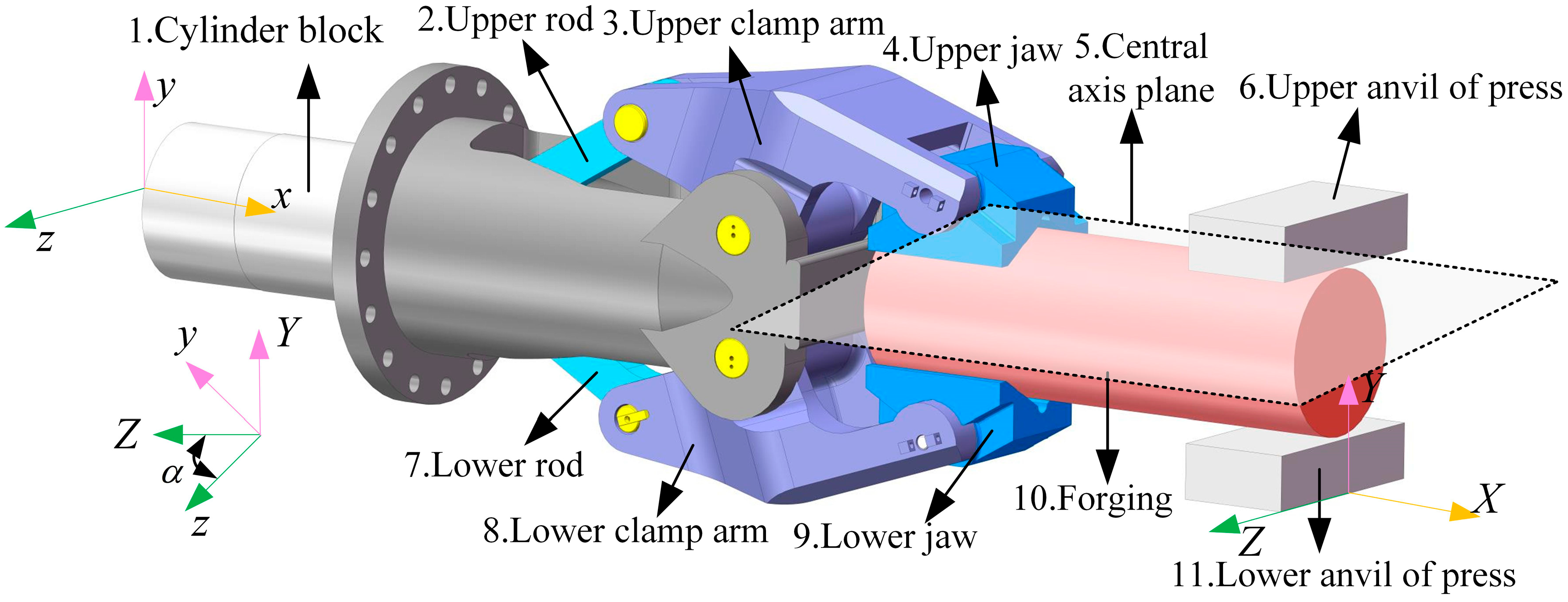
4]. A crucial aspect of this development is the need for an instantaneous and highly accurate method of sensing forging load forces, particularly under the demanding conditions of high temperatures and complex operational environments. The core issue lies in effectively sensing the internal forces exerted by the forging piece. Given that the clamping mechanism drives the jaws to open and close and is positioned closest to the high-temperature forging, it inherently offers a unique advantage in force sensing. Therefore, this study outlines the behavior of the clamping mechanism under forging conditions and establishes a comprehensive force sensing model.
The clamping mechanism of the manipulator is a critical component in the forging process, playing a vital role in bearing the forces exerted on the forging [
5]. This mechanism, which directly contacts the forging, primarily utilizes pin joints, with all motion pairs rigidly connected, ensuring accurate transmission of mechanical information. Consequently, the clamping mechanism can be employed for indirect sensing of the forces on the forging. Numerous researchers have conducted in-depth studies on clamping force models and force transmission ratios in clamping mechanisms [
6,
7,
8]. For example, Yan et al. examined the motion characteristics of clamps and modeled the plastic deformation of forgings during the forging process [
9]. They also proposed a method for modeling the stiffness of robotic arms and calculated the resistance applied to the clamps [
10]. Yang et al. derived expressions for force transmission ratios in clamping mechanisms based on their characteristics, calculated forces in clamping states at different horizontal and vertical positions, and developed formulas for clamping force at various rotational angles [
11,
12]. Dai et al. used Pro/Engineer’s static analysis function to establish a clamping mechanism model, calculating clamping force, link force, and clamping arm force, revealing the relationships between these forces, the diameter of the forging, and the clamping angle [
13]. Li et al. employed Lagrange equations to build a dynamic model of the manipulator clamping mechanism, predicting the forces acting on the clamping mechanism [
3]. These studies underscore the extensive research on force transmission ratios, clamping force models, and the dynamic and static characteristics of clamping mechanisms, providing a solid theoretical foundation for further development of mechanical models for clamping mechanisms and forgings, as well as for exploring their force transmission mechanisms.
At its core, force sensing research focuses on the precise detection and characterization of both the magnitude and direction of applied forces [
14]. Force sensing measurement methods are generally classified into two categories: direct and indirect. Direct methods involve enhancing the design and strategically placing force sensing devices within the targeted mechanical component, allowing for the direct capture of force-related data at specific detection points [
15,
16]. However, the challenging environment of forging operations, characterized by harsh conditions, complicates this approach. Placing force sensing devices directly at the end of the clamping mechanism is highly susceptible to adverse factors such as high temperatures, heavy loads, and impacts, making the direct method unsuitable for force sensing analyses in forging operations.
The indirect method of force sensing arises from the limitations of direct force measurement [
17]. In this approach, force sensing equipment is strategically placed along the force transmission path within the mechanical system [
18]. By collecting data from these designated points, the force information at the mechanism’s terminus can be inferred, achieving the desired force sensing objective. For instance, Lei investigated force feedback in an arm-wrestling robot, determining the optimal placement of strain gauges at the wrist and elbow. By collecting and processing force data from these locations, the external force at the robot’s end was indirectly determined [
19,
20]. Similarly, Wei et al. developed a mapping relationship between the force states of high-speed train wheels and wheel-rail forces by collecting and analyzing indirect physical quantities such as strain, displacement, and acceleration. This facilitated the indirect identification and sensing of wheel-rail forces [
21]. In surgical robotics, Yang et al. proposed the development of virtual work and force feedback models for flexible rod mechanisms. Through a detailed examination of structural and material properties, they achieved indirect force sensing at the robotic arm’s end [
22]. Zhao et al. innovatively used the current values of drive motors at joint points to estimate forces at the mechanism’s terminus [
23]. Furthermore, Li et al. conducted comprehensive studies on cable-driven mechanisms within surgical robot systems, addressing the challenge of estimating clamping forces for surgical instruments by analyzing various designs and employing Gaussian process regression filters [
24]. Additionally, Chen et al. implemented pin sensors at pivotal hinge points of excavator buckets, enabling the sensing and identification of excavation forces through force data collected at these hinge points within the force transfer model [
25].
Evidently, the indirect method relies on mechanical models as intermediary frameworks. By extrapolating force data from detection points along the mechanism, insights into the force dynamics at the mechanism’s terminus can be derived. Given the challenging conditions of high temperatures and heavy loads in forging operations, exploring indirect force sensing methods is particularly relevant for this study. During forging processes, the generated force signals typically manifest as complex, multidimensional datasets, necessitating the integration of advanced data mining and machine learning techniques for real-time monitoring and analysis. The BP algorithm-based neural network has demonstrated exceptional performance in function approximation and pattern recognition. Many researchers have made significant advancements in developing and applying neural networks [
26,
27,
28]. As an indispensable tool across various fields, it offers a viable solution for improving force perception accuracy in this study.
For example, Lai et al. optimized BP neural network hyperparameters to establish a predictive model for mining pressure in working faces using IAPSO-BP techniques [
29]. Wang et al. employed numerical simulation results as training datasets to construct a BP neural network model for predicting void sizes and load positions, effectively leveraging simulation outcomes for model development [
30]. Li et al. addressed the complex coupling of deformation information in AI-LI alloy under varying conditions such as temperature, humidity, and pH levels by developing a predictive model for the alloy’s mechanical properties using a BP neural network framework [
31]. Similarly, Ma et al. constructed a prediction model for the ultimate displacement ratio of concrete columns using BP neural networks, effectively addressing the challenge of shear destruction influenced by multiple coupled factors [
32]. Ma et al. also emphasized the BP neural network’s exceptional accuracy in predictions, highlighting its effectiveness in addressing complex structural phenomena.
Given the demanding operational environment of forging machines, characterized by harsh conditions, dynamic load fluctuations, and multi-axis force coupling, traditional force measurement methods often fail to meet the high precision and load sensing demands. These conventional techniques typically struggle with the complexities of measuring forces in such environments, requiring more advanced solutions. To overcome these limitations, this study introduces a novel approach based on a BP neural network, aiming to enhance force sensing capabilities in clamping mechanisms under forging conditions.
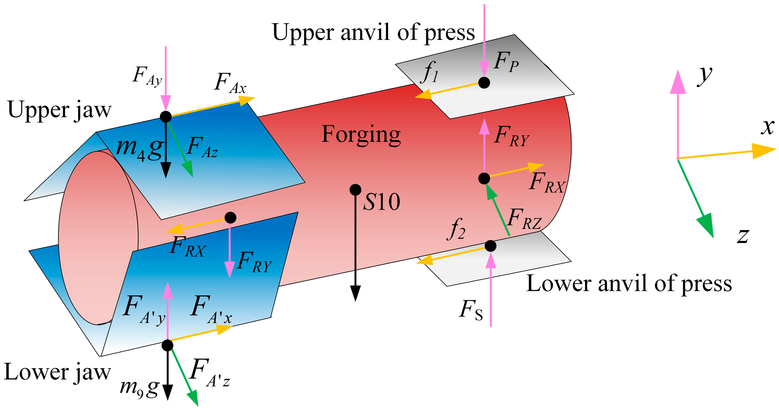
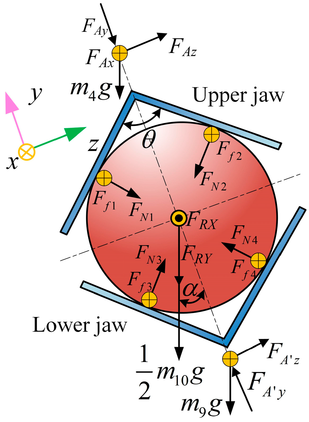
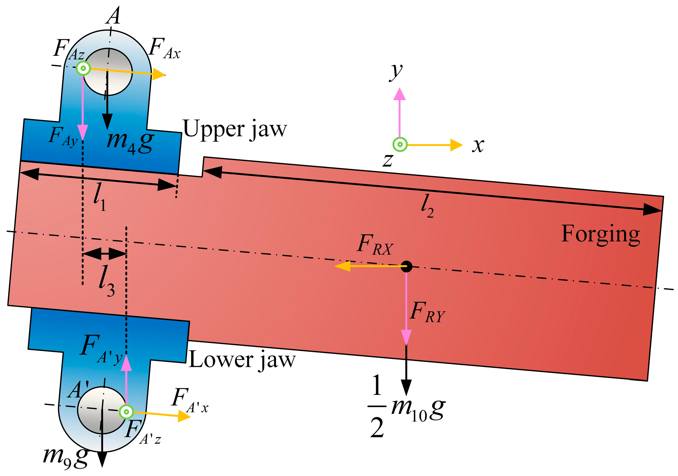
This paper focuses on the mechanical modeling of the clamping mechanism under forging conditions, exploring the force flow transmission and sensing characteristics inherent to the mechanism. By analyzing the force state of each forging, the deformation resistance of high-temperature forgings is indirectly sensed. Additionally, an indirect force sensing model is developed using the BP neural network, facilitating research into the decoupling of deformation resistance under forging conditions. Concurrently, analogous tests of the clamping mechanism are conducted to validate the accuracy of the force sensing model. The goal of this paper is to elucidate the force transmission laws of the clamping mechanism in operational machines under forging conditions, thereby providing a foundation for active compliance control.
3. Results and Discussion
3.1. Hinge Point Force Law and Hinge Point Sensitivity Analysis
When the clamping mechanism rotates clockwise by 45°, with FRX and FRY varying between −105 N and 105 N, the mapping relationship between the hinge point forces of the clamping mechanism and the horizontal and vertical deformation resistance of the forging is analyzed.
Figure 7 illustrates the correlation between the forces exerted at each hinge point of the clamping mechanism in the local coordinates
x,
y, and
z, and the deformation resistances
FRX and
FRY. It is evident from
Figure 7 that the relationship between each hinge point force and
FRX and
FRY exhibits a linear trend.
As illustrated in
Figure 7a–c, the forces at hinge points B and C show considerable overlap, which is due to their role as action points on the rods. The two-force rod properties of these points result in consistent force conditions. Additionally, each hinge point is significantly more sensitive to forces in the
x direction compared to the
y and
z directions, with hinge points A and O demonstrating the highest sensitivity in this regard. Therefore, the force characteristic curves of
FAX and
FOX are particularly useful for determining the horizontal deformation resistance
FRX.
Similarly,
Figure 7d–f indicate that the sensitivity of each hinge point to forces in the
x and
y directions is relatively high. Notably, points A’ and O’ show superior sensitivity to
y-direction forces compared to other hinge points. Thus, the force characteristic curves of
FA′Y and
FO′Y are valuable for identifying the vertical deformation resistance
FRY.
A comprehensive comparison of
Figure 7a–f shows that the force characteristic curves of points A, A’, O, and O’ are preferable for recognizing the forging deformation resistances
FRX and
FRY. Given the potential ambiguity in direction and magnitude when relying on a single hinge point, using the force data from double hinge points A and O enhances the accuracy of the deformation resistance identification.
3.2. Experimental Design and Data Samples
3.2.1. Test Bench and Principle
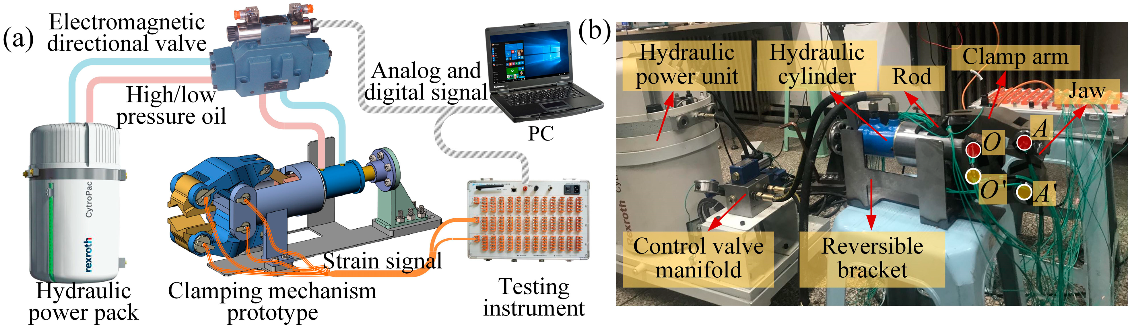
The clamping mechanism’s test prototype has been scaled down proportionally based on similarity theory. To assess the force state at the A and O hinge points in the test prototype, a stress–strain detection method is employed, as illustrated in
Figure 8.
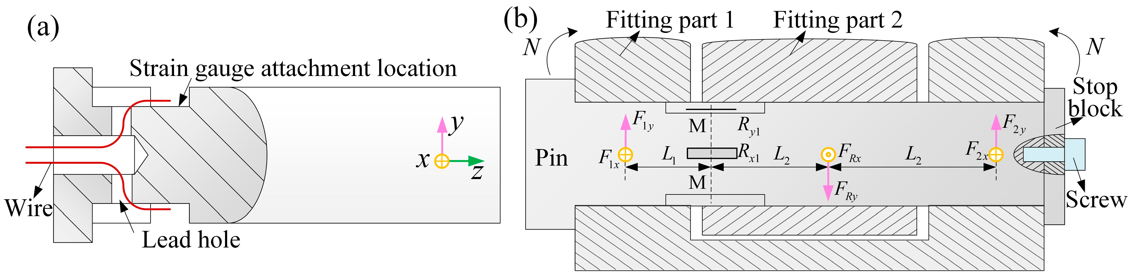
The chosen strain gauge model is BX120-0.5AA, which features a gauge factor of 2.08 ± 1% and a resistance value of 120 ± 0.2 Ω. To facilitate the attachment of the strain gauge, the pin form was modified by machining a groove and lead holes necessary for strain gauge installation. Adjustments were made to the pin design based on the dimensions at different hinge points to accommodate the strain gauge and routing of its leads, as shown in
Figure 9a. The wires are routed through the lead holes into the groove where the strain gauge is attached. For accurate measurements in the confined space, a 1/4-bridge circuit was constructed in both the
x and
y directions, with a common temperature compensation gauge integrated into the main circuit. The layout and installation plan for the strain gauges are depicted in
Figure 9b.
Considering the potential fluctuations in hinge force caused by voltage variations and hydraulic output instability during testing, each experiment was repeated 10 times. Statistical analysis was then performed to obtain the average value, minimizing the impact of these fluctuations on the results. During repeated experiments, all sensors were pre-calibrated using a standard force calibration device before testing to ensure measurement accuracy. After the experiments, the calibration process was repeated to verify that no significant sensor drift had occurred. Additionally, the strain gauges were carefully inspected before each test to ensure they remained securely attached and positioned correctly.
The pin is installed between fitting part 1 and fitting part 2, acting as a connecting element. It is secured with a stopper and a screw to ensure a fixed connection between the pin and fitting part 1, preventing relative rotation. The pin can rotate relative to fitting part 2, forming a rotational pair. In this setup, the axial tensile force and torque acting on the pin are considered negligible. Consequently, the primary stress on the pin arises from the bending moment
N induced by the force transmission through the mechanism, leading to bending strain on the pin. A 1/4 bridge circuit with temperature compensation is employed for measurement accuracy. Strain gauges
R1x and
R1y are used to measure the bending strain in the
x and
y directions, respectively. The relationship between strain and resistance change of the strain gauge is given by Equation (11), while the corresponding voltage change output is described by Equation (12).
Based on the force relationship of the pin, the force scenario can be simplified to a mid-span load with fixed constraints at both ends. Specifically, fitting part 1 provides fixed constraints at both ends of the pin, while the pin bears the load from fitting part 2. The forces at three positions are orthogonally decomposed; the forces at the two ends of fitting part 1 are decomposed into
F1x,
F1y,
F2x, and
F2y. The force exerted by fitting part 2 on the pin is decomposed into
FRx and
FRy, with the assumed directions depicted in
Figure 9. The strain gauges are positioned at the M-M cross-section, located in the gap between the two fitting parts on the pin. Thus, the strain measured by the gauges corresponds to the strain at the M-M cross-section. According to the principles of material mechanics, the bending moment
N at the M-M cross-section can be determined using Equation (13).
where
E represents the material’s elastic modulus, and
Wz is the section modulus of the pin (mm
3) for resisting bending.
FRx and
FRy are the reaction forces at the hinge point that need to be determined. The method of sections and equilibrium equations are applied to analyze the forces acting on the pin in the x direction, leading to the expression shown in Equation (14). Similarly, a force analysis on the pin in the y direction results in the expression for the forces in that direction, as shown in Equation (15).
3.2.2. Data Samples
To comprehensively assess the performance of the clamping mechanism, deformation resistance data are collected under three distinct working conditions: vertical clamping, 45° tilting clamping, and horizontal clamping.
The deformation resistance of the forging, FRX and FRY, varies from −1000 N to 1000 N, with data collection points spaced at 200 N intervals, resulting in a total of 363 sets of network learning data, Xd, obtained through orthogonal matching. Under the same conditions, but with a data collection point intervals of 500 N, 27 sets of test data, Td, are acquired. To ensure the accuracy of the neural network testing, the collected values are cross-checked, and any overlapping data are excluded. As a result, 24 groups of actual test data, Td, are retained for rigorous testing and validation of the neural network model.
The BP neural network was trained on a workstation equipped with an Intel Core i7-10700 K processor, 32 GB of RAM, a 1 TB SSD for storage, and an NVIDIA GTX 1660 graphics card. The software environment included Windows 10 as the operating system, TensorFlow 2.0 as the primary framework for neural network training, and additional tools such as Python 3.8 and MATLAB R2017b for data preprocessing and analysis. The training time varied depending on the network complexity and dataset size. For the BP neural network model used in this study, training on a dataset of 100,000 samples typically required approximately 3 to 5 h on the specified hardware configuration. More complex network architectures and larger datasets may necessitate additional computational time, depending on hyperparameter tuning and experimental settings.
3.3. Number of Hidden Nodes in BP Neural Network
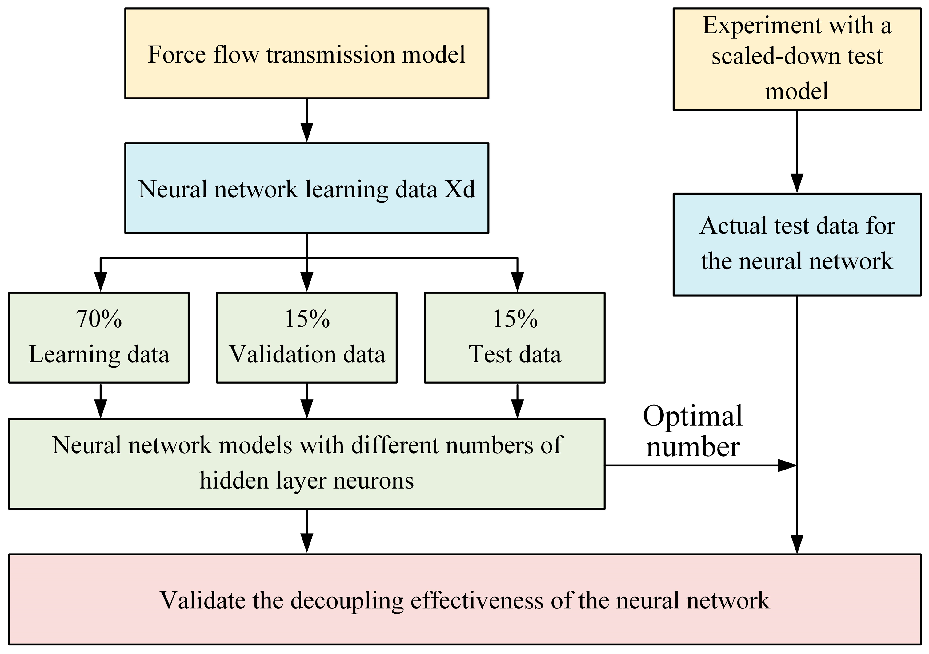
The decoupling approach in this study is illustrated in
Figure 10. First, the learning data are divided into three sets: 70% for training, 15% for validation, and the remaining 15% for testing. Based on the established neural network decoupling model, different numbers of hidden layer neurons are selected, and simulation analysis and validation are performed using the learning data to determine the optimal number of neurons that achieve the best decoupling performance. Finally, actual test data collected from experiments, which include error fluctuations, are used to verify the effectiveness of the neural network-based decoupling approach.
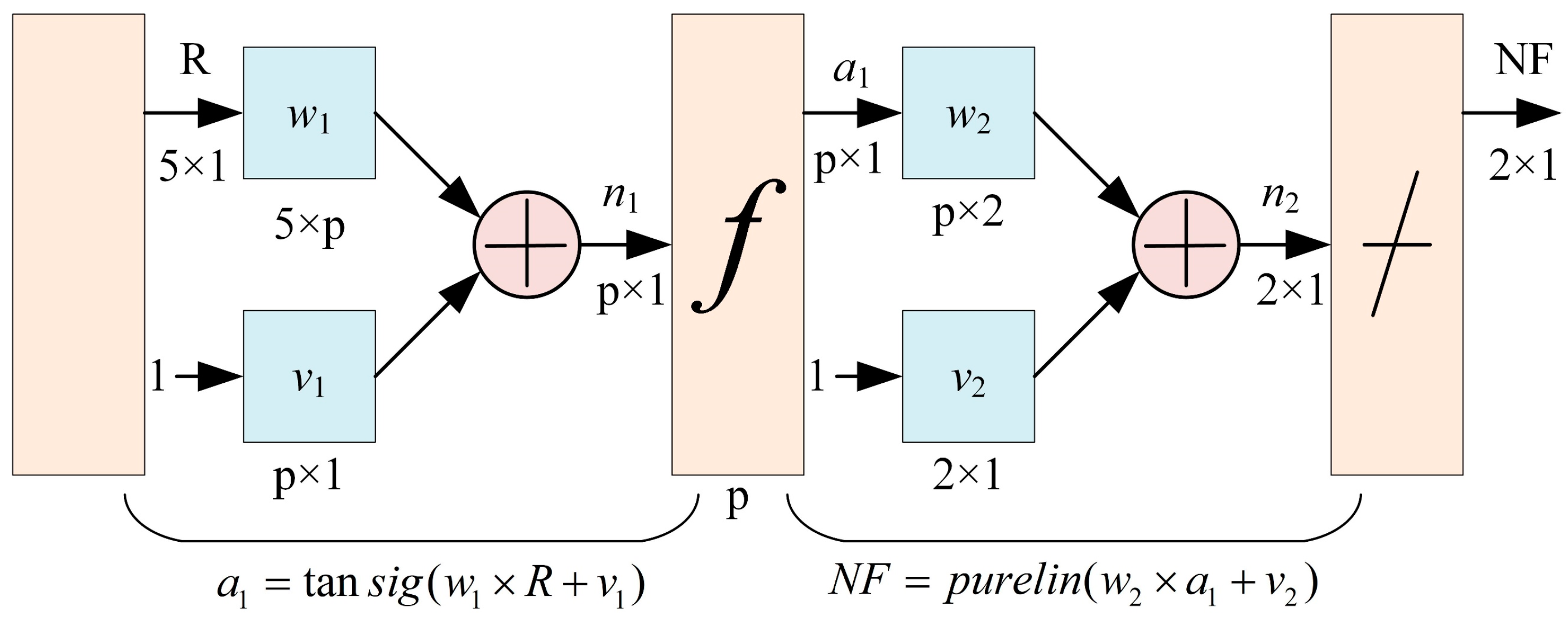
The number of neurons in the hidden layer of the BP neural network is a crucial hyperparameter, as it significantly affects the training process, including learning time, error rate, fault tolerance, and generalization ability. An inadequate or excessive number of hidden neurons can negatively impact the network’s performance. Therefore, the effect of different hidden neuron counts on the training outcomes was explored. In practical applications, the selection of the number of hidden neurons is typically based on empirical knowledge and multiple experiments, as there is no universally ideal mathematical formula for its determination. However, an empirical formula, given by , can be used to estimate the range of possible hidden neurons, where p represents the number of hidden layer neurons, i is the number of input layer neurons, d is the number of output layer neurons, and a is an integer between 1 and 10. Based on this guideline, experiments were conducted with different hidden layer neuron counts ranging from 4 to 13 to train the force sensing model of the clamping mechanism. The optimal number of hidden neurons was determined based on the training performance of the neural network.
Based on the learning data X
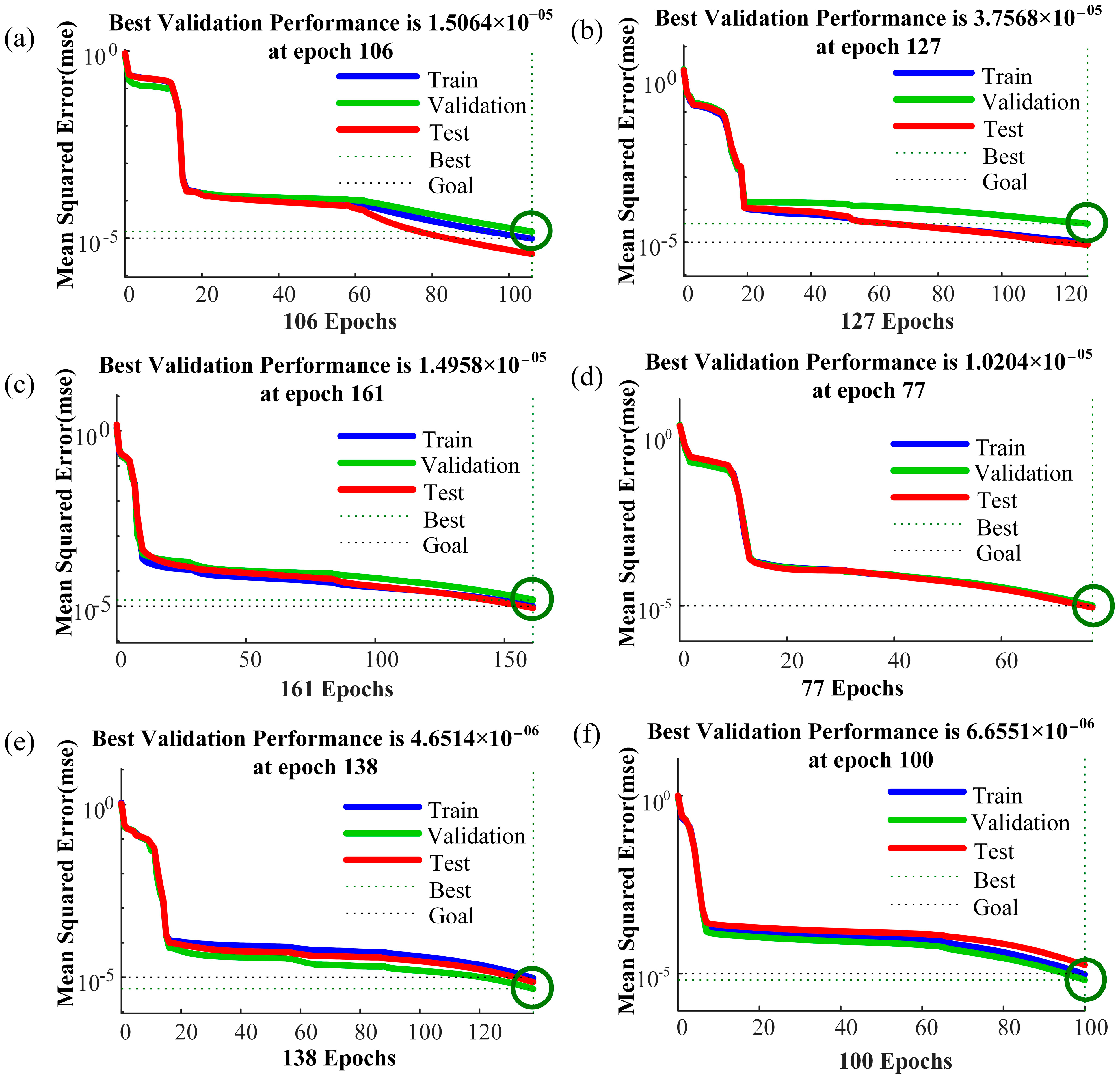
d, the neural network of the force sensing model for the clamping mechanism is trained using varying numbers of hidden layer units, ranging from 4 to 13. Throughout the training process, the target means square error (MSE) is set to 0.00001, with a learning rate of 0.01. The maximum number of training iterations is capped at 1000, utilizing the Levenberg–Marquardt algorithm as the training function. Given the regularity of training outcomes, to conserve space, the training results for neural networks with hidden layer unit numbers 5, 7, 9, 11, 12, and 13 are presented and illustrated in
Figure 11. As the number of hidden layer nodes increases, the mean square error of the neural network’s training results gradually decreases. Interestingly, when the number of hidden layer nodes reaches 11, the training line (Train), validation line (Validation), and test line (Test) of the neural network converge closely. This convergence occurs around the 77th training iteration, indicating effective force decoupling. Subsequently, as the number of hidden layer nodes continues to increase, the mean square error of the training results further decreases to the 10-6 level. However, beyond this point, the three lines representing the training results begin to diverge, diminishing the convergence effect and, consequently, the decoupling effectiveness. Therefore, the optimal number of nodes in the hidden layer of the neural network decoupling model is determined to be 11, as it achieves the desired force decoupling with optimal convergence and effectiveness.
3.4. Decoupled Analysis of Force Sensing Model for Clamping Mechanism
Upon determining the optimal number of hidden layer nodes as 11, the actual test data (Td) were incorporated into the neural network model to evaluate its decoupling effectiveness on error-containing fluctuation data.
Figure 12a shows a comparison between the experimental and theoretical data for horizontal deformation resistance. The maximum relative error is 11.2%, with the majority of test points exhibiting a relative error within 10%, and the average relative error calculated at 6.1%.
Figure 12b presents a comparison for vertical deformation resistance, where the maximum relative decoupling error is 16.8%, and the average relative error is 9.5%. The decoupling results in the horizontal direction demonstrate better accuracy compared to the vertical direction.
The hinge point forces measured in the experiment fluctuate within a certain range. In addition to voltage fluctuations in the stress–strain testing system, the primary cause of these fluctuations is the continuous variation in the output force of the driving hydraulic cylinder, leading to small fluctuations in the hinge point forces. Given that the pin diameters at hinge points A and O are relatively large, resulting in a larger bending section modulus for these two pins, the hinge point forces at these locations are more sensitive to system fluctuations. This sensitivity results in more noticeable fluctuations, as observed from the strain measurements.
Overall, the experimental and theoretical data exhibit consistent trends, with the average error remaining within 10%. Therefore, the indirect sensing method proposed in this study is deemed effective in detecting both the direction and magnitude of the workpiece’s deformation resistance.
4. Conclusions
During operation in the forging workshop, the forging manipulator clamps the workpiece and coordinates with the press to perform movements such as parallel lifting, feeding, side shifting, tilting, and other actions. However, in actual forging production, the clamping mechanism can experience instability during the forging process. When the high-temperature workpiece undergoes plastic deformation under the impact force of the press, significant deformation resistance is generated within the workpiece. The immense deformation resistance applied to the manipulator can cause the clamping mechanism to lose its grip on the workpiece, resulting in the workpiece falling off and potentially causing safety hazards.
To address the challenge of measuring and perceiving the load deformation resistance force in the forging operation, this paper focuses on the clamping mechanism. It investigates the force flow transfer dynamics between each hinge point of the clamping mechanism and the deformation resistance of the forging. Through sensitivity analysis of the forces acting at each hinge point, characteristic hinge points with heightened force awareness are identified. The paper then utilizes a BP neural network for decoupling analysis of the forces perceived at these characteristic hinge points under deformation resistance conditions.
In comparison to traditional force sensing methods, which often struggle with dynamic fluctuations and multi-axis force coupling in forging operations, the proposed BP neural network-based methodology offers significant advancements. Unlike conventional techniques that rely on direct force measurements, our approach decouples internal forging forces at multiple hinge points, enabling more accurate and reliable force sensing.
The key conclusions of this study are as follows:
The force sensing model established for the clamping mechanism under various clamping states reveals a consistent trend in the forces at the upper and lower hinge points, which exhibit linearity with respect to FRX and FRY. The hinge points, particularly A and O, show heightened sensitivity to forces in the x and y directions.
The BP neural network decoupling model, based on the force sensing model, demonstrates that due to the sagging phenomenon of the forging during testing, force fluctuations in the x direction at hinge points are smaller compared to those in the y direction. This results in superior decoupling effectiveness for horizontal deformation resistance compared to vertical resistance. The average relative error in forging deformation resistance decoupling remains within 10%, confirming the neural network’s efficacy in accurately perceiving both the direction and magnitude of forging deformation resistance.
While this study has made positive contributions to force sensing modeling and decoupling analysis for the clamping mechanism of forging machines, several limitations remain. For instance, although BP neural networks were used for decoupling analysis, future research will further refine the details of the neural network, such as optimizing the number of hidden layers based on relevant literature and experimental validation [
33]. Additionally, we will explore the application of generative machine learning (ML) techniques to reduce the reliance on labeled data in supervised learning.

