Article

Design and Analysis of a Portable Robot for Venous Blood Sampling

1
Changchun Institute of Optics, Fine Mechanics and Physics, Chinese Academy of Sciences, 3888 Dong Nanhu Road, Changchun 130033, China
2
University of Chinese Academy of Sciences, 19A Yuquan Road, Beijing 100049, China
*
Author to whom correspondence should be addressed.
Machines 2025, 13(3), 203; https://doi.org/10.3390/machines13030203
Submission received: 23 January 2025 / Revised: 19 February 2025 / Accepted: 20 February 2025 / Published: 28 February 2025
(This article belongs to the Section Robotics, Mechatronics and Intelligent Machines)

Abstract

:
Venous blood sampling is a common procedure in medical diagnosis and treatment. However, the stationary manual blood sampling method in current use not only requires human resources but also is inconvenient for elderly persons and patients with limited mobility. To address this issue, this paper proposes a portable robot for venous blood sampling that features a 6-P-RR-R-RR horizontal parallel mechanism in its main structure. This design is better adapted to the shape of the human arm than previous robots, with an offset RR-hinge structure to increase the mechanism’s workspace. The introduction of offset hinge variables makes the kinematic solution more complex than that for conventional parallel mechanisms. This paper uses the kinematic constraint characteristics of the offset hinge to establish a kinematic model of the parallel mechanism, and the Newton–Raphson numerical iterative method is used to perform the computation. The kinematic model and its solutions are verified using kinematics simulation. The robot’s workspace is validated through special pose calculations and simulations to ensure that it meets the required specifications. A test system was built, and the accuracy of the parallel mechanism’s motion was verified.

1. Introduction

Blood sampling is often necessary for medical diagnosis and treatment. The purpose of this procedure is to enable analysis of the blood components by collecting venous blood specimens, with the aim of assisting with clinical diagnosis and treatments. The most important step in the blood sampling process is the venous puncture, particularly in routine blood tests at the elbow vein [1]. At present, it is only possible to rely on medical staff to collect blood manually. The skill of the medical staff and the location and size of the patient’s blood vessels can cause fluctuations in the success rate of venipuncture. Specific cases, including patients who are obese or have a deeper complexion, elderly people, and children, can present major challenges to the physical and mental strength of medical staff [2]. The current venous blood sampling examination mode is to have patients report to a hospital or a designated blood sampling station for a blood sampling examination. Elderly persons and patients with severe illnesses attend blood sampling examinations very frequently. This may be inconvenient for elderly people and patients who cannot go to the hospital or a specific blood sampling site alone. As the average age of the population continues to increase, medical resources will be under more pressure, which will undoubtedly worsen the problems above [3]. Therefore, the demand for automation, miniaturization, and increased portability of blood sampling equipment has been strengthening.
The automation of venous blood sampling largely involves three main technologies, namely, venous imaging technology, puncture sensing technology, and robotics technology. Venous imaging technology can provide information for puncture point decisions. At present, venous imaging technology is mature, with techniques that include near-infrared (NIR) light imaging [4], ultrasonic (US) imaging [5], and vascular positioning technology based on temperature differences [6]. Puncture sensing technology is used to determine whether the blood sampling needle has entered successfully and to ensure that it did not penetrate the remote wall of the vein. At this stage, the main techniques are puncture force sensing [7] and electrical impedance sensing [8].
With the ongoing advancements in robotics technology, venous blood sampling robots equipped with venous imaging and puncture sensing equipment have gradually emerged, and they are gradually being applied in clinical medicine. For example, the VeeBot was developed using an industrial robot arm equipped with imaging and puncture systems [9]. The device uses an EPSON robotic arm to provide six degrees of freedom (6-DOF) of pose for the puncture needle, combined with a dual-arm dexterous robot with 17-DOF that is used to guide needle insertion. ugh the robotic arm has more freedom and flexibility, its large size, weight, and high cost greatly reduce the clinical availability of this equipment. In 2019, MagicNurse announced the development of the world’s first automatic unmanned blood sampling equipment [10] that can be applied in clinical use. Its robot has been piloted in some hospitals in Beijing and can achieve a fully automatic venous blood sampling process without the need for assistance from additional medical staff. However, the machine has a total of 21 axes, causing a highly complex structure and control system, high cost, and significant physical volume. It is impossible to sample blood portably. Chen et al. [11,12] developed a compact venous injection robot called VeniBot in 2021. The device is equipped with an NIR camera and an ultrasonic probe to provide vein location and depth information. Because of the series configuration of VeniBot, errors accumulate on the end effector, and its accuracy is difficult to guarantee. Although the physical volume of the blood sampling robot is less than that in the previous example, it is still quite far away from being portable.
When compared with series robots, parallel robots have advantages that include high precision, compact structures, good rigidity, and fast response speeds [13]. These robots can reach resolutions on the micron level or even the nanoscale and, thus, are finding increasing numbers of applications in the field of medical devices in recent years. Shoham et al. [14] proposed a micro-parallel robot to assist with spinal trauma surgery that can perform accurate positioning and adjust the position of the drill or needle during an operation. Nakano et al. [15] developed a parallel robot for vitreous retinal surgery that can provide micron-scale resolution and micron-level positioning accuracy, and it has demonstrated good operability. Among the multiple configurations of parallel robots, the Gough–Steward 6-DOF parallel platform [16,17] has a unique structure and forms a good fit with the shapes of human limbs, and it has also been used in limb bone traction and fixation equipment. Wendlandt et al. [18] developed an intelligent external bone fixator that can effectively improve the accuracy and stability of bone movement through computer-aided planning, thereby both promoting bone healing and improving the patient’s safety and comfort. Ding’s research team [19] also developed an ankle-foot rehabilitation assist device based on the Stewart platform that can help a patient’s ankle to achieve rehabilitation in six directions with reduced errors to within 0.5 mm.
Conventional parallel robots mostly use spherical hinges or Hooke hinges as their motion joints. These parallel robots often have shortcomings that include small working spaces and large manufacturing and installation errors. The application of offset hinges as motion joints can help to avoid these shortcomings. Grossmann and Kauschinger [20] studied three different forms of offset hinges and discussed the feasibility of using these hinges to replace traditional Hooke hinges. Li et al. [21] analyzed the workspace for a class of offset hinges and verified that the parallel robot with the offset hinges had a larger workspace than the parallel robot using spherical hinges and Hooke hinges. However, because there is a certain distance between the two rotation axles of the offset hinge, new offset parameters were introduced, and thus, the kinematics of the parallel mechanisms with offset hinges became quite complex. Hu and Lu [22] proposed an offset 3-UPU parallel mechanism and provided its inverse kinematics and forward kinematics equations. Ji and Wu [23] studied a 3-RRPRR parallel mechanism and analyzed the kinematics, singularity, and workspace of the mechanism. However, when the degrees of freedom for parallel robots with offset hinges increase to six, the kinematic mathematical model becomes more complex. Because its structure does not satisfy the condition of the analytical solution [24], its kinematics can only be solved by numerical solution. Dalvand and Shirinzadeh [25] used Newton–Raphson iterative method to solve the forward kinematics of a parallel mechanism with 6-RRCRR configuration. Zhang et al. [26] used the Denavit–Hartenberg (D-H) method to analyze the kinematics of a 6-P-RR-RR parallel robot. Morell et al. [27] used machine learning methods to solve for the forward kinematics of a 6-RRCRR parallel robot with offset hinges.
Based on the analysis above, this study aims to design a portable robot for venous blood sampling. To adapt to the shape of the human arms, the robot’s main structure uses a 6-P-RR-R-RR horizontal parallel configuration. Compared with conventional serial-structured venous blood sampling robots, the parallel structure provides significant advantages, including higher stiffness, greater accuracy, a lower self-weight-to-load ratio, and a more compact structure. However, the main disadvantage of the conventional parallel mechanism lies in its limited workspace. To address this issue, the robot’s motion joints are designed as offset RR-hinges, which can greatly increase the workspace for the parallel mechanism. However, the introduction of these offset RR-hinges also brings new variables that make the kinematic solution more complex when compared with conventional parallel mechanisms. In this study, a kinematic model of the parallel mechanism is established by using the kinematic constraint characteristics of the offset hinges, and the Newton–Raphson numerical iterative method is used for the computation. Subsequently, kinematics simulation is used to validate the correctness of the kinematic model and its solution. The robot’s workspace is verified through calculations and simulations at specific poses. Finally, the construction of the test system and the test methods for the parallel mechanism are introduced, and results for step accuracies are presented.

2. Structure Design

2.1. Robot Workflow Analysis and Module Division

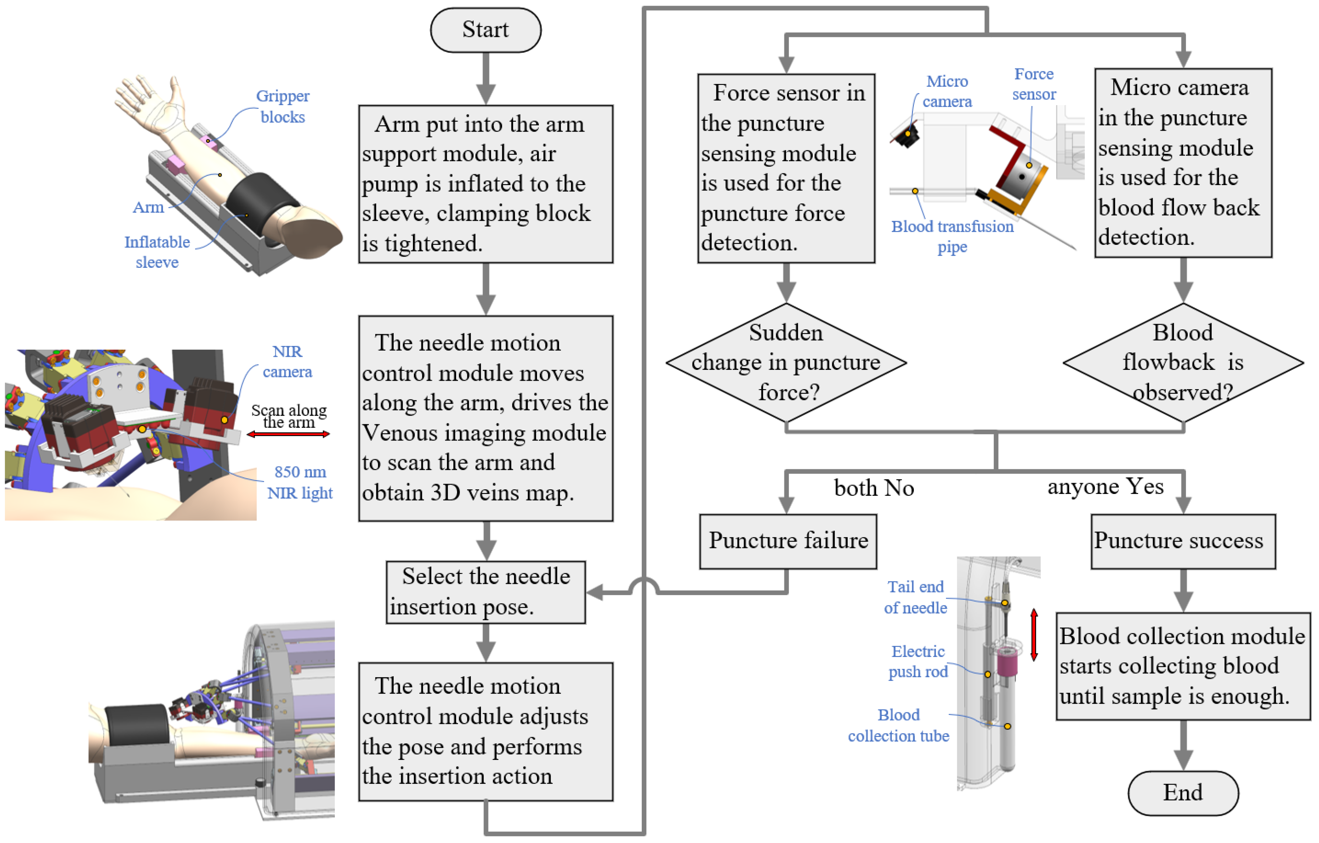
Before the specific design is produced, research and a detailed analysis of the project must be conducted to ensure the feasibility of the venous blood sampling robot design scheme. First, by observing and investigating the operating process for artificial blood sampling performed by medical staff [28,29] in combination with the current technological developments in the robotics field, the workflow for venous blood sampling robots was abstracted, as shown in Figure 1.
Analysis of the action flow has shown that to complete the automatic blood sampling function, the complete robot has many functional requirements, which makes it difficult to achieve the required function through a design process. Therefore, the core functions of the robot must be analyzed. The core function is to insert the needle into the target insertion point and withdraw the needle after completing the blood sampling procedure. The core functions mainly rely on the design of a 6-DOF motion control mechanism to perform the required actions. Because of individual differences, the best insertion position and direction are different, and thus, the end effector with the needle requires a certain dexterous workspace range. At the same time, to meet the portability requirements of the robot, the size of the entire machine must be limited to within a certain range. The first phase of the research is to design a robot that meets the above functions and requirements.
Subsequently, based on the modular design concept, the complete venous blood sampling robot is decomposed into the following five functional modules:
1.
Needle motion control module, which enables the blood sampling needle to perform venipuncture actions at the specified position and direction;
2.
Arm support module, which provides pneumatic pressure for the vein and secures the arm to minimize movement, thereby increasing the venipuncture success rate;
3.
Venous imaging module, which performs imaging of the elbow veins and uses the venous image information to guide the motion control module and position the blood collection needle accurately at the puncture site;
4.
Puncture sensing module, which uses sensors to detect the penetration status of the vascular wall and determine whether the blood collection needle has successfully entered the venous vessel;
5.
Blood collection module, which collects the patient’s blood into the blood collection tube.

2.2. Structural Design of Complete Machine and Modules

By analyzing the robot’s workflow and its functional modules, the overall structure of the robot was designed. The three-dimensional model and the structural layout of the complete machine are shown in Figure 2. Figure 2a shows the structural design of the complete machine.
The structural design of each function module is described as follows.

2.2.1. Needle Motion Control Module

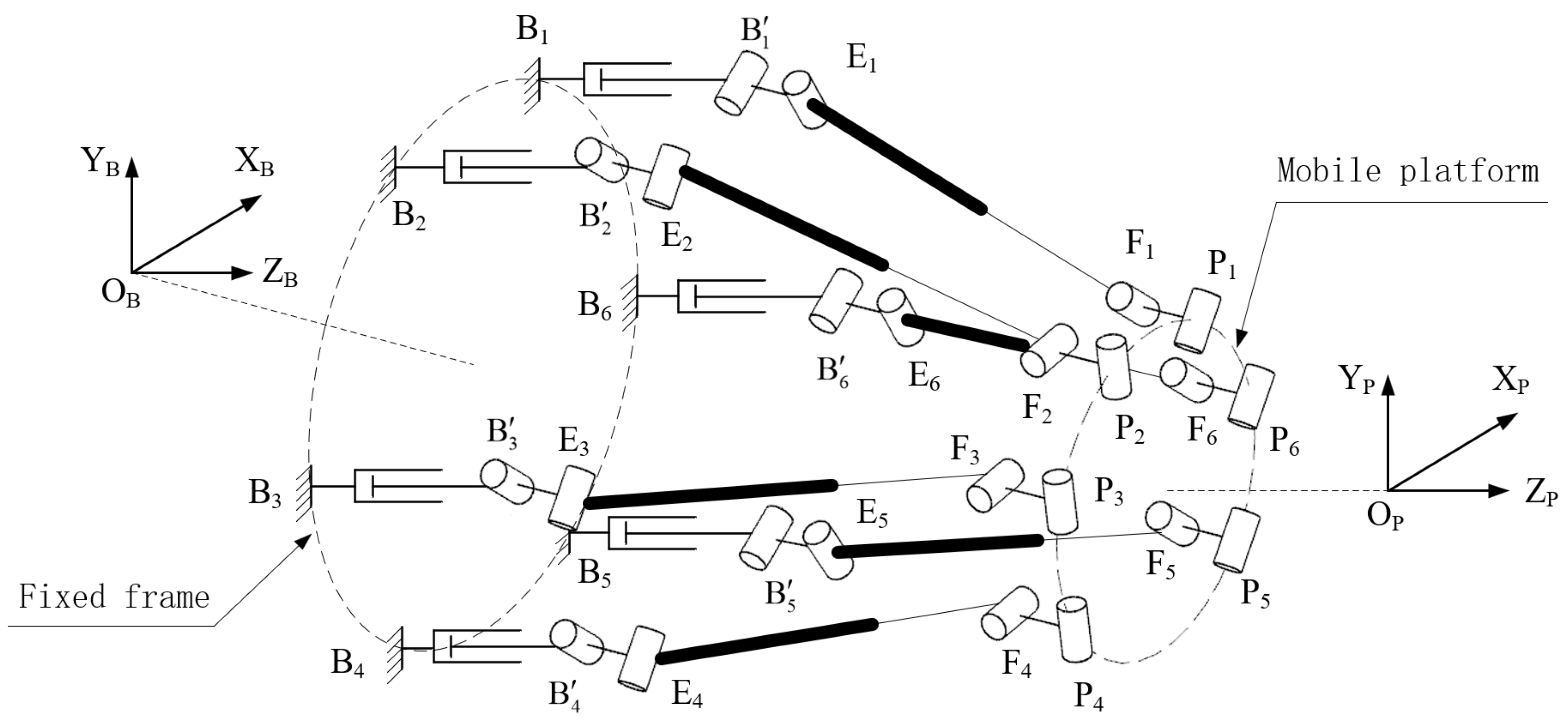
This module serves as the core functional component of the robot and is responsible for controlling the needle to be inserted into the target vein with the specified position and direction. A 6-DOF motion control mechanism must be designed to meet the performance criteria established in the analysis earlier. By referring to the classic Gough–Stewart platform configuration, the mechanism is modified into a 6-P-RR-R-RR horizontal parallel mechanism, as illustrated in Figure 3.
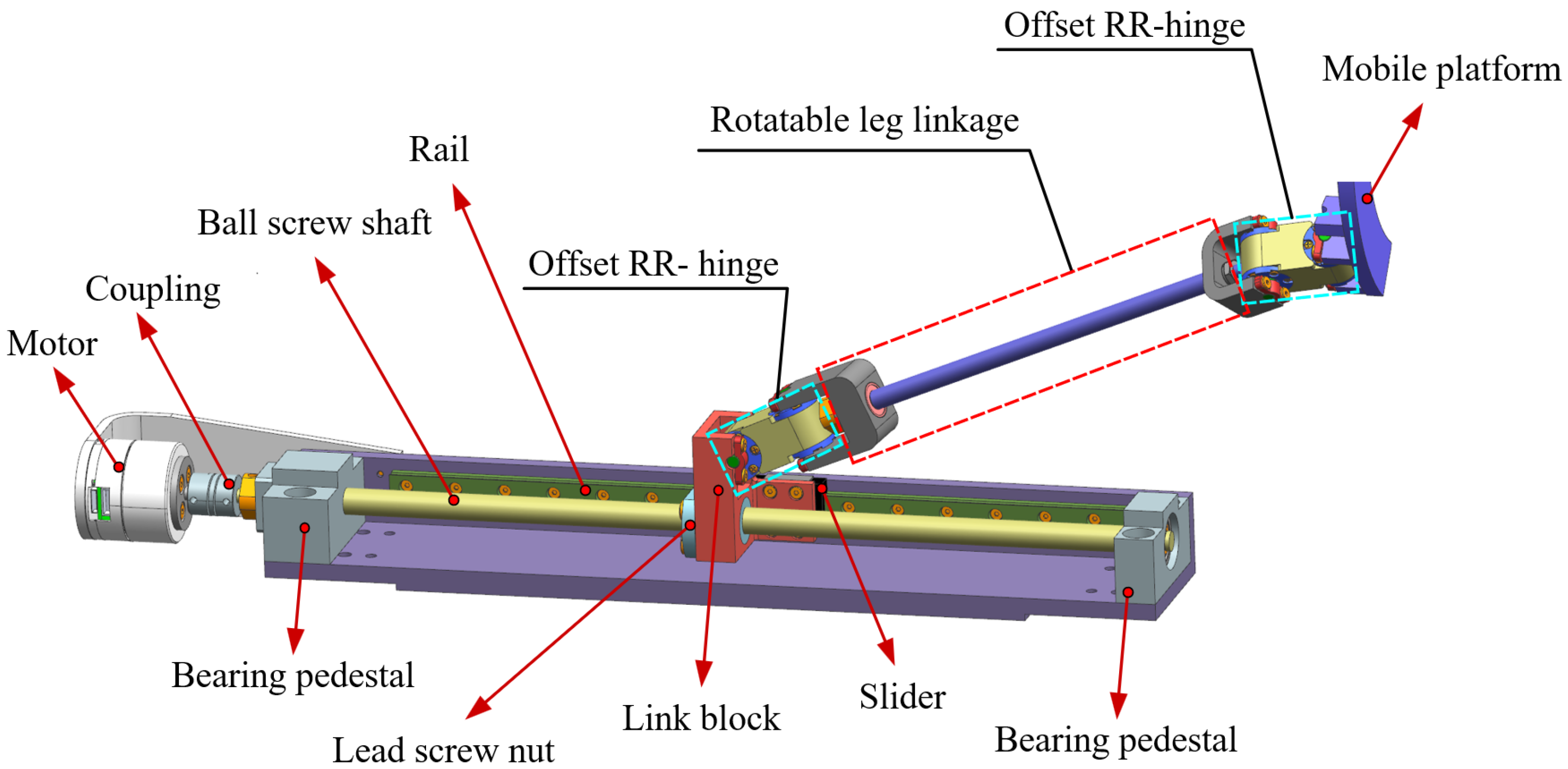
Based on this configuration, the structural design of the needle motion control module is developed, as shown in Figure 2b. The module consists of six P-RR-R-RR kinematic chains that act as support legs, with the structure of each leg shown in detail in Figure 4. Notably, the motion joint uses an offset RR-hinge configuration, where the two hinge axes are mutually perpendicular but do not intersect in space, thus creating an offset between the hinge axes. When compared with spherical hinges and Hooke hinges, this design provides a larger workspace. The mobile platform is semi-annular in shape, thus ensuring a high degree of suitability with the human’s arm. The motor provides the driving force for the ball screw shaft, thus moving the lead screw nut, the link block, and the slider along the guide rail in a linear motion and forming the P-prismatic pair. The offset hinge serves as a motion joint and connects the rotatable leg linkage with the link block and the moving platform, which constitute the RR-revolute pair. The rotatable leg linkage forms the R-revolute pair.

2.2.2. Blood Collection Module

The structure of the blood collection module is shown in Figure 2c. The module uses an electric push rod to insert the tail end of the needle into a blood collection tube and then retracts the needle when the desired blood volume has been collected. This module is integrated into the outer casing of the robot, thus effectively reducing the overall size of the robot and enhancing its portability.

2.2.3. Arm Support Module

The structure of the arm support module is shown in Figure 2d. This module is equipped with pressure and pneumatic sensors that enable both arm fixation and pneumatic pressure while preventing potential injury from being caused by the application of excessive clamping force or overpressure. Additionally, the arm support has sliding grooves on both sides that are aligned with the base, thus allowing the support to be retracted into the robot’s body when not in use, which further enhances the robot’s portability.

2.2.4. Venous Imaging Module

The venous imaging module uses a binocular near-infrared (NIR) imaging scheme that consists primarily of an 850 nm NIR light panel and two NIR cameras. This module is integrated into the end effector, as illustrated in Figure 2e. The working principle of the module is to use the 850 nm NIR light panel as an illumination source to irradiate the patient’s arm; because of the varying NIR light absorption rates of biological tissues, differences in the reflected or transmitted NIR light allow distinctions to be made between blood vessels and the other tissues. The reflected NIR light is captured using the two NIR cameras. By applying the principle of binocular disparity, depth information is computed for each pixel included in the venous imaging data, and a 3D point cloud map is generated.

2.2.5. Puncture Sensing Module

The puncture sensing module uses a combined detection scheme that involves puncture force sensing and blood flow back detection. The primary components of the module include a one-dimensional force sensor and a micro camera. This module is integrated into the end effector, as illustrated in Figure 2f. The puncture force detection uses a one-dimensional force sensor to monitor the sudden reduction in puncture force that occurs when the needle tip penetrates the vascular wall, thus indicating successful wall penetration. The blood flow back detection relies on the phenomenon where, upon the needle piercing the inner wall of the vein, the intravascular pressure causes blood to flow back into the tube because it is higher than the infusion tube pressure. Machine vision algorithms are then used to determine whether the needle has successfully entered the vein.
The interaction and workflow between each module are shown in Figure 5.

3. Kinematic Analysis of Needle Motion Control Module

The fundamental task of robotic motion analysis is position analysis, which involves resolving the positional relationship between the input and output components of the robot. This analysis serves as a foundation for the subsequent workspace analysis. As the robot’s core functional module, the needle motion control module must undergo a kinematic analysis to ensure precise needle control during robotic operation.

3.1. Parameters of Mechanism

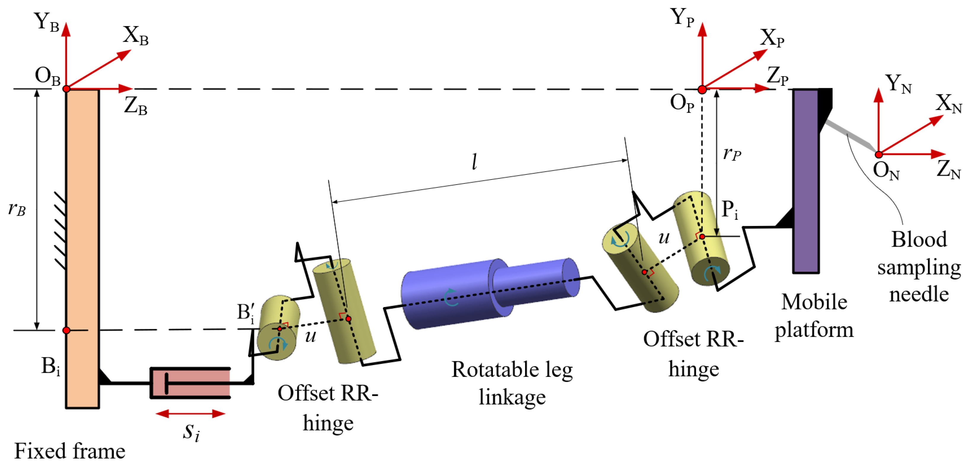
Per the analysis earlier, the primary structure of this module is a 6-P-RR-R-RR horizontal parallel mechanism, where each leg in the parallel mechanism has a P-RR-R-RR kinematic chain. Therefore, a schematic of the leg kinematic chain has been established, as shown in Figure 6, along with the corresponding coordinate systems built to define the parameters of the 6-P-RR-R-RR parallel mechanism.
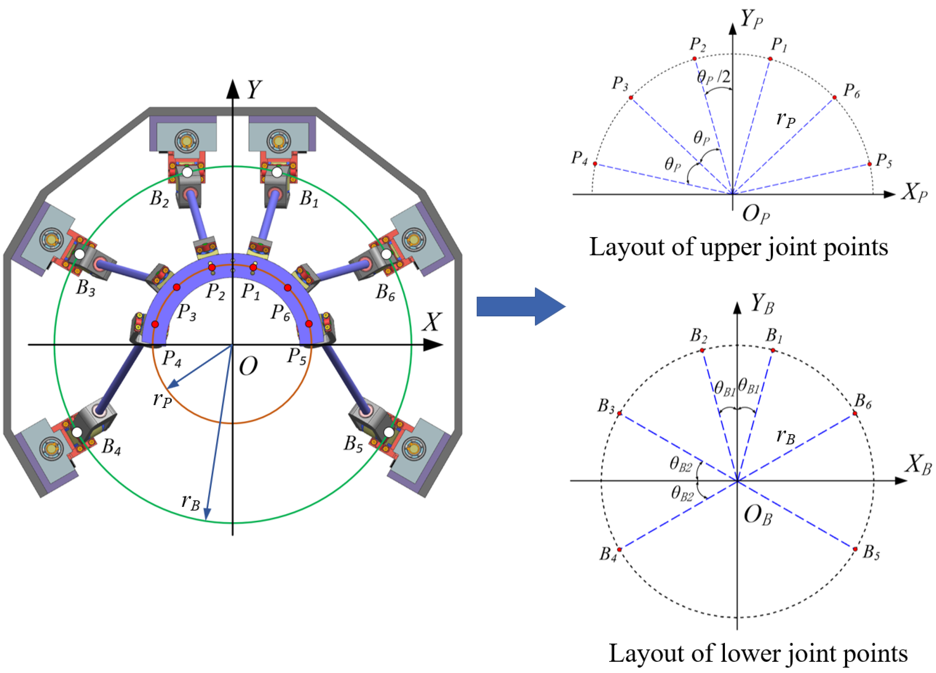
As shown in Figure 6, B i represents the center point of the hinge axis connected to the link block (which are hereinafter referred to as the “lower joint points”). B i represents the projection of B i on the fixed frame’s end plane. O B is the center of the distribution circle of B i . P i represents the center point of the hinge axis connected to the mobile platform (which are hereinafter referred to as the “upper joint points”). O P is the center of the distribution circle of P i . The distributions of the upper and lower joint points are shown in Figure 7.
A global coordinate system O B X B Y B Z B is established, with O B as the origin. A local coordinate system O P X P Y P Z P of the mobile platform is established at O P . The blood sampling needle is fixed to the mobile platform, and a local coordinate system O N X N Y N Z N of the needle that is parallel to O P X P Y P Z P is established at the needle tip O N . The radius of the upper joint points distribution circle is r P , and the angle between any two adjacent joint points is θ P . The radius of the lower joint points distribution circle is r B , which is determined primarily by the parameters θ B 1 and θ B 2 . The hinge offset is denoted by u, the length of the rotatable leg linkage is l, and s i represents the slider displacement along the guide rail direction (i.e., the Z B -axis). The coordinates of the needle tip O N in the coordinate system O P X P Y P Z P are ( x N , y N , z N ) . The configuration parameters for the parallel mechanism are listed in Table 1.
Because the blood sampling needle is connected in a fixed manner to the mobile platform and the local coordinate system O N X N Y N Z N is parallel to the local coordinate system O P X P Y P Z P , the transformation matrix T O N O P from O N X N Y N Z N to O P X P Y P Z P is given by
T O N O P = 1 0 0 x N 0 1 0 y N 0 0 1 z N 0 0 0 1
The local coordinate system O N X N Y N Z N in the global coordinate system O B X B Y B Z B is determined using a six-dimensional vector x , y , z , α , β , γ T . Here, x , y , z T and α , β , γ T represent the position vector and the attitude vector of the needle’s local coordinate system O N X N Y N Z N in the global coordinate system O B X B Y B Z B , respectively. During rotation, the mobile platform initially rotates about the X B -axis by the angle α , then rotates about the rotated Y B -axis by the angle β , and finally rotates about the twice-rotated Z B axis by the angle γ . Based on this sequence, the transformation matrix T O N O B from O N X N Y N Z N to O B X B Y B Z B is given as follows ( for convenience, sin ( · ) is abbreviated as s ( · ) and cos ( · ) is abbreviated as c ( · ) ; this convention is used throughout this document):
T O N O B = c β c γ c β s γ s β x c α s γ + s α s β c γ c α c γ s α s β s γ s α c β y s α s γ c α s β c γ s α c γ + c α s β s γ c α c β z 0 0 0 1

3.2. Definition of the Local Coordinate Systems for the Joint Points

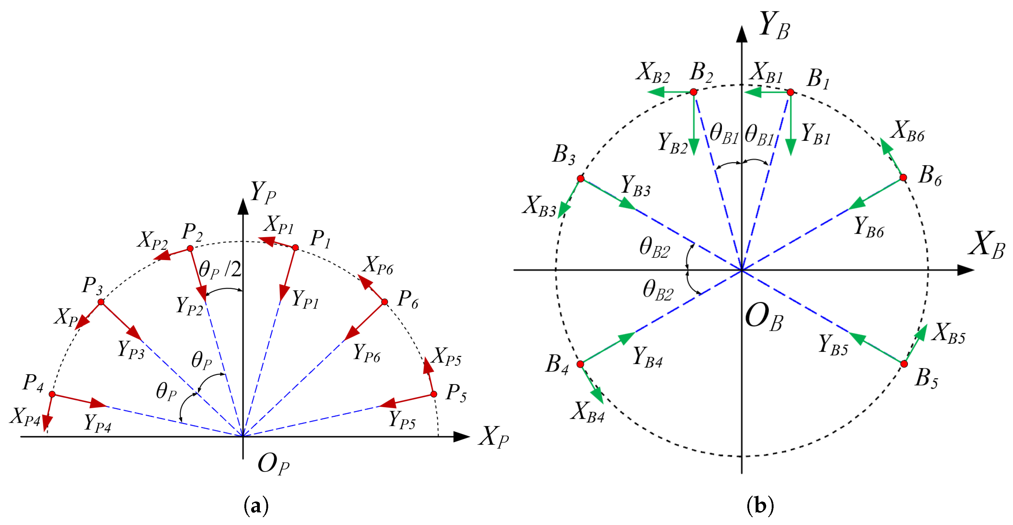
Because of the presence of the offset hinges, each leg introduces two additional hinge variables. To describe the motion of the mechanism more effectively, three sets of local coordinate systems are established, as illustrated in Figure 8. It is worth noting that for ease of assembly, the hinge axis at B 1 and B 2 are arranged in a direction parallel to X B . Based on the global coordinate system O B X B Y B Z B , in the local coordinate system B i X B i Y B i Z B i , ( i = 1 , , 6 ) , X B i is defined at the position of the lower joint point B i . The X B i -axis aligns with the hinge axis, while the Z B i -axis is parallel to the global Z B -axis. Another local coordinate system B i X B i Y B i Z B i , ( i = 1 , , 6 ) is established at projection point B i . This coordinate system is generated by translating B i X B i Y B i Z B i along the Z B direction. A local coordinate system P i X P i Y P i Z P i , ( i = 1 , , 6 ) is then established at the upper joint point P i , with the X P i axis being aligned along the hinge axis and the Z P i axis being parallel to the global Z B axis.
Based on the definition of the local coordinate systems, the position of the origin of the lower joint point local coordinate system B i can be expressed in the global coordinate system O B X B Y B Z B as
B i O B = r B c θ B i r B s θ B i s i T
where θ B i = π 2 + ( 1 ) i · θ B 1 ( i = 1 , 2 ) ; θ B i = π + ( 1 ) i · θ B 2 ( i = 3 , 4 ) ; and θ B i = ( 1 ) i · θ B 2 ( i = 5 , 6 ) .
In addition, in the coordinate system O P X P Y P Z P , the position of the origin of the local coordinate system P i can be expressed as
P i O P = r P c θ P i r P s θ P i 0 T
where θ P i = π 2 + ( 2 i 3 ) · θ B 2 ( i = 1 , 2 , 3 , 4 ) and θ P i = ( 2 i 9 ) · θ B 2 ( i = 5 , 6 ) .
Rotating the global coordinate system O B X B Y B Z B counterclockwise around the Z B -axis by an angle η B i causes it to align with the orientation of the local coordinate system B i X B i Y B i Z B i . Therefore, the transformation matrix T B i O B from the global coordinate system O B X B Y B Z B to the local coordinate system B i X B i Y B i Z B i can be given as
T B i O B = c η B i s η B i 0 r B c θ B i s η B i c η B i 0 r B s θ B i 0 0 1 s i 0 0 0 1
where η B i = π ( i = 1 , 2 ) ; η B i = π 2 + ( 1 ) i · θ B 2 ( i = 3 , 4 ) and η B i = π 2 + ( 1 ) i · θ B 2 ( i = 5 , 6 ) .

3.3. Analysis of Inverse Kinematics

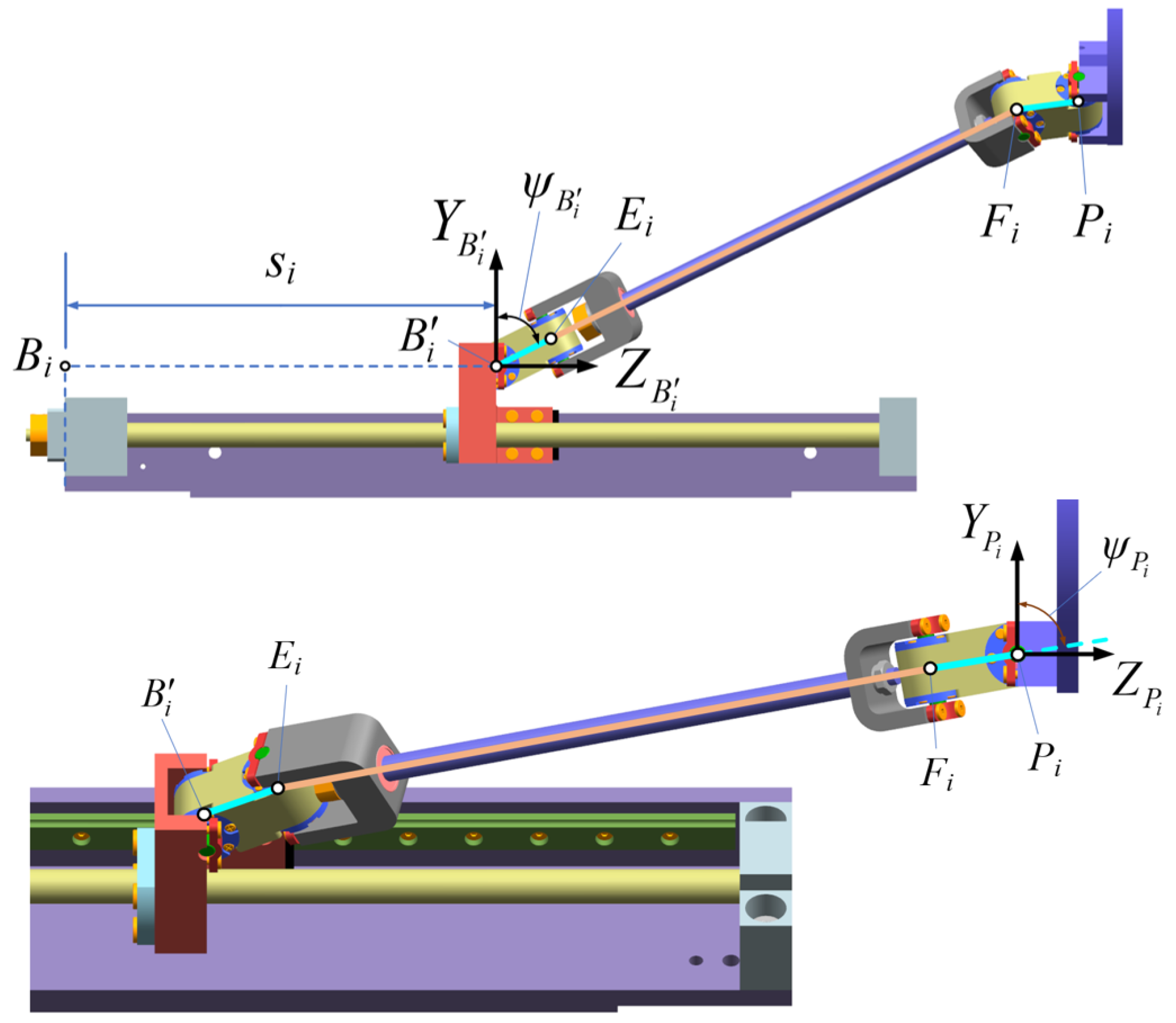
The inverse kinematic analysis of the parallel mechanism is the process of giving the spatial pose x , y , z , α , β , γ of the needle’s local coordinate system O N X N Y N Z N within the global coordinate system O B X B Y B Z B and then solving for the displacements of the six sliders s i . Because of the introduction of the hinge offset, new constraint equations need to be established based on the kinematic constraints of the hinges. As shown in Figure 9, point E i is the center of the connecting axis between the lower hinge and the linkage, while point F i is the center of the connecting axis between the upper hinge and the linkage. The angle ψ B i denotes the angle between the axis Y B i and the line B i E i , and ψ P i denotes the angle between the axis Y P i and the line P i F i . These angles ψ B i and ψ P i represent the two additional hinge variables introduced by use of the offset hinges.
Based on the structural properties of the offset hinge, the coordinate vector of E i in the coordinate system B i X B i Y B i Z B i can be expressed as
E i B i = 0 u · c ψ B i u · s ψ B i 1 T
Similarly, the coordinate vector of F i in the coordinate system P i X P i Y P i Z P i is expressed as
F i P i = 0 u · c ψ P i u · s ψ P i 1 T
Therefore, the length of the rotatable leg linkage can be expressed using the coordinate vectors of E i and F i . Because the linkage length, which is denoted by E i F i B i , is known to be l, the following equation can then be established:
E i F i B i T · E i F i B i l 2 = 0
Furthermore, it is important to note that within the coordinate system B i X B i Y B i Z B i , the projections of the lines B i E i and E i F i on the Y B i Z B i plane are collinear. This implies that the angle between B i E i and the Y B i -axis is always equal to the angle between E i F i and the Y B i -axis within the Y B i Z B i plane. Similarly, within the coordinate frame P i X P i Y P i Z P i , the angle between E i F i and the Y P i -axis is equal to the angle between E i P i and the Y P i -axis. Consequently, the following two equations can be established:
tan ψ B i = Z E i F i B i Y E i F i B i
tan ψ P i = Z E i F i P i Y E i F i P i
where Z E i F i B i and Y E i F i B i represent the components of the vector E i F i B i along the Z B i and Y B i directions, respectively. Similarly, Z E i F i P i and Y E i F i P i denote the components of the vector E i F i P i along the Z P i and Y P i directions, respectively.
The vectors E i F i B i and E i F i P i can be expressed as
E i F i B i = F i B i E i B i = T B i 1 O B · T O N O B · T O N 1 O P · T P i O P · F i P i E i B i
E i F i P i = F i P i E i P i = F i P i T P i 1 O P · T O N O P · T O N 1 O B · T B i O B · E i B i
Because Z E i F i B i , Y E i F i B i , Z E i F i P i , and Y E i F i P i can all be expressed in terms of ψ B i , ψ P i , and s i , Equations (9) and (10) can then be rewritten as
sin ψ B i cos ( ψ B i ) = a 1 · sin ( ψ P i ) + a 2 · sin ( ψ B i ) + a 3 · s i + a 4 a 5 · cos ( ψ P i ) + a 6 · cos ( ψ B i ) + a 7 · s i + a 8
sin ψ P i cos ( ψ P i ) = b 1 · sin ( ψ P i ) + b 2 · sin ( ψ B i ) + b 3 · s i + b 4 b 5 · cos ( ψ P i ) + b 6 · cos ( ψ B i ) + b 7 · s i + b 8
where a i and b i ( i = 1 , , 8 ) are all known quantities.
Solving the system of equations composed of Equations (8), (13), and (14), the three variables of each leg, s i , ψ B i , and ψ P i , can be obtained. Because this system is nonlinear, the Newton–Raphson numerical iterative method is used to solve. The system of equations can be expressed in the following form:
F i 1 ψ B i , ψ P i , s i = 0 F i 2 ψ B i , ψ P i , s i = 0 F i 3 ψ B i , ψ P i , s i = 0
where F i 1 , F i 2 , and F i 3 represent the left-hand sides of Equations (8), (13), and (14), respectively.
The leg variables ψ B i , ψ P i , and s i in Equation (15) can be solved using the following iterative formulation:
ψ B i ψ P i s i ( n + 1 ) = ψ B i ψ P i s i ( n ) F i 1 ψ B i F i 1 ψ P i F i 1 s i F i 2 ψ B i F i 2 ψ P i F i 2 s i F i 3 ψ B i F i 3 ψ P i F i 3 s i 1 · F i 1 F i 2 F i 3 ( n )
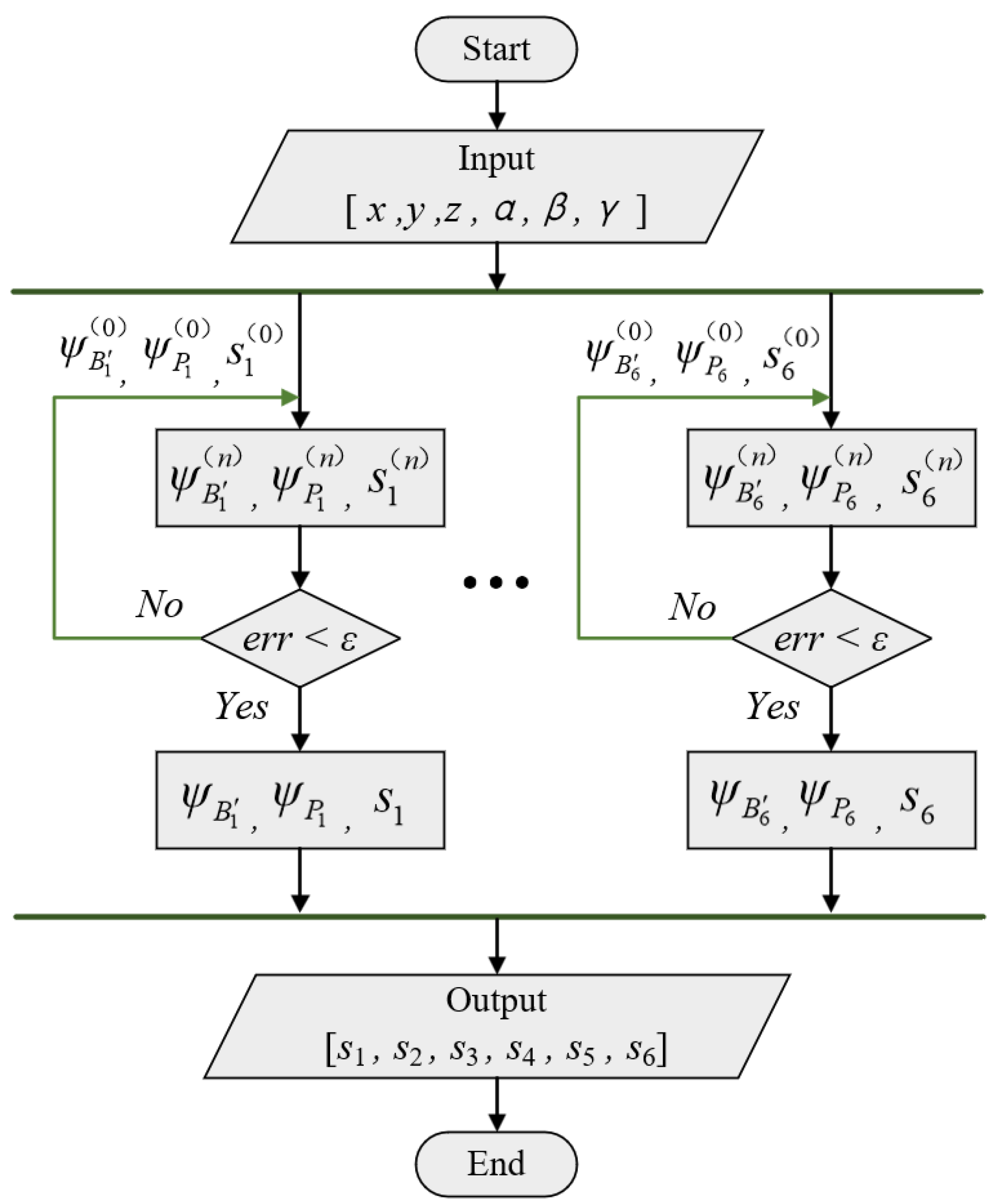
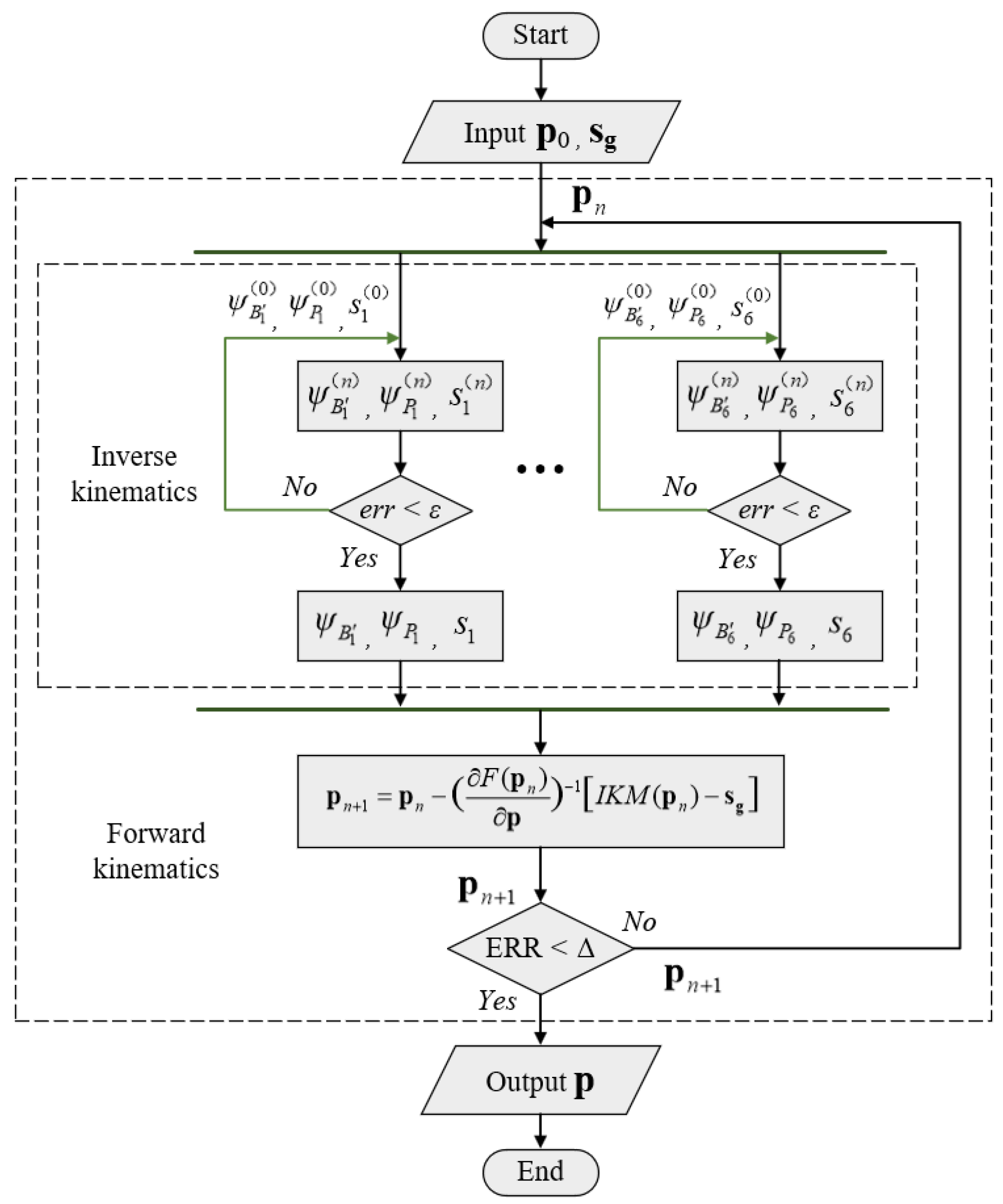
When the initial values are provided and the calculation error tolerance is specified, numerical computations can be performed using the iterative Equation (16). Given the convergence error of ε = 1 × 10 9 , all leg variables in the i-th leg chain can be solved out under the specified error conditions. Consequently, the inverse kinematics solution for the 6-P-RR-R-RR parallel mechanism can be obtained. The numerical iterative solution process for the inverse kinematics of the parallel mechanism is illustrated in Figure 10.

3.4. Analysis of Forward Kinematics

The forward kinematic analysis of the parallel mechanism is the process of giving the displacements of the six leg-driven sliders s i ( i = 1 , , 6 ) and then solving for the pose p = [ x , y , z , α , β , γ ] T of the needle in the local coordinate system. Because the forward kinematic problem of the parallel mechanism lacks an analytical solution and involves solving a system of nonlinear equations, numerical methods are used to provide the solution.
For a given set of slider displacements s g = s g 1 , s g 2 , , s g 6 T , the function F ( p ) is defined as
F ( p ) = I K M ( p ) s g
where I K M ( p ) represents the inverse kinematic solution that corresponds to the needle pose p = [ x , y , z , α , β , γ ] T , thus obtaining the vector for the leg displacements s = [ s 1 , s 2 , , s 6 ] T . If p s is the ideal forward kinematic solution, then I K M ( p s ) is equal to s and, thus, ensures that F ( p S g ) = 0 .
Equation (17) is solved using the Newton–Raphson numerical iterative method, and the numerical iterative formula is given as follows:
p n + 1 = p n F ( p n ) p 1 I K M ( p n ) s g
where
F p = s 1 x s 1 y s 1 z s 1 α s 1 β s 1 γ s 2 x s 2 y s 2 z s 2 α s 2 β s 2 γ s 6 x s 6 y s 6 z s 6 α s 6 β s 6 γ
After an initial value p 0 is specified, the numerical iterative is performed using the iterative formula given in Equation (18). The iteration is considered to be convergent when the error condition p n + 1 p n 1 × 10 9 is met, thus indicating that p n + 1 is the final solution for the forward kinematics analysis. The flowchart for the solution of the forward kinematics analysis for the parallel mechanism is shown in Figure 11.

3.5. Kinematic Simulation Verification

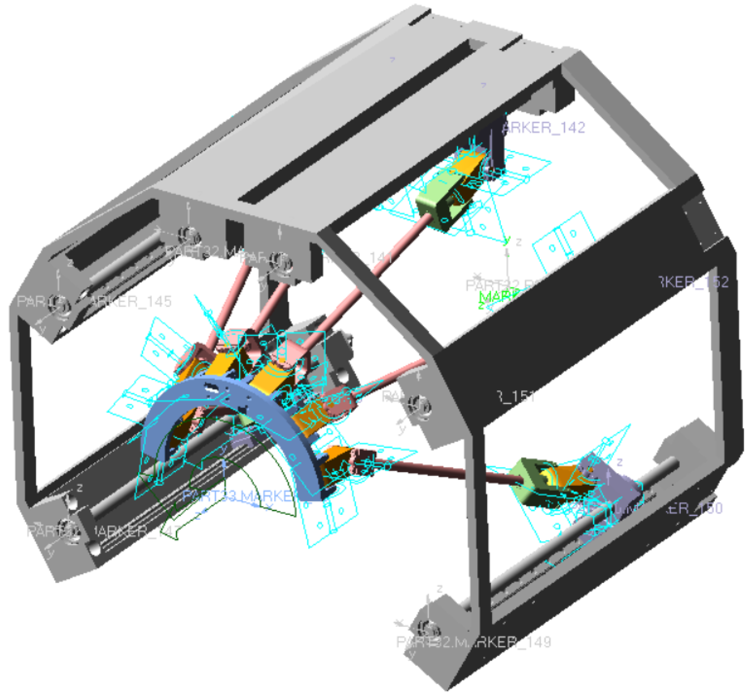
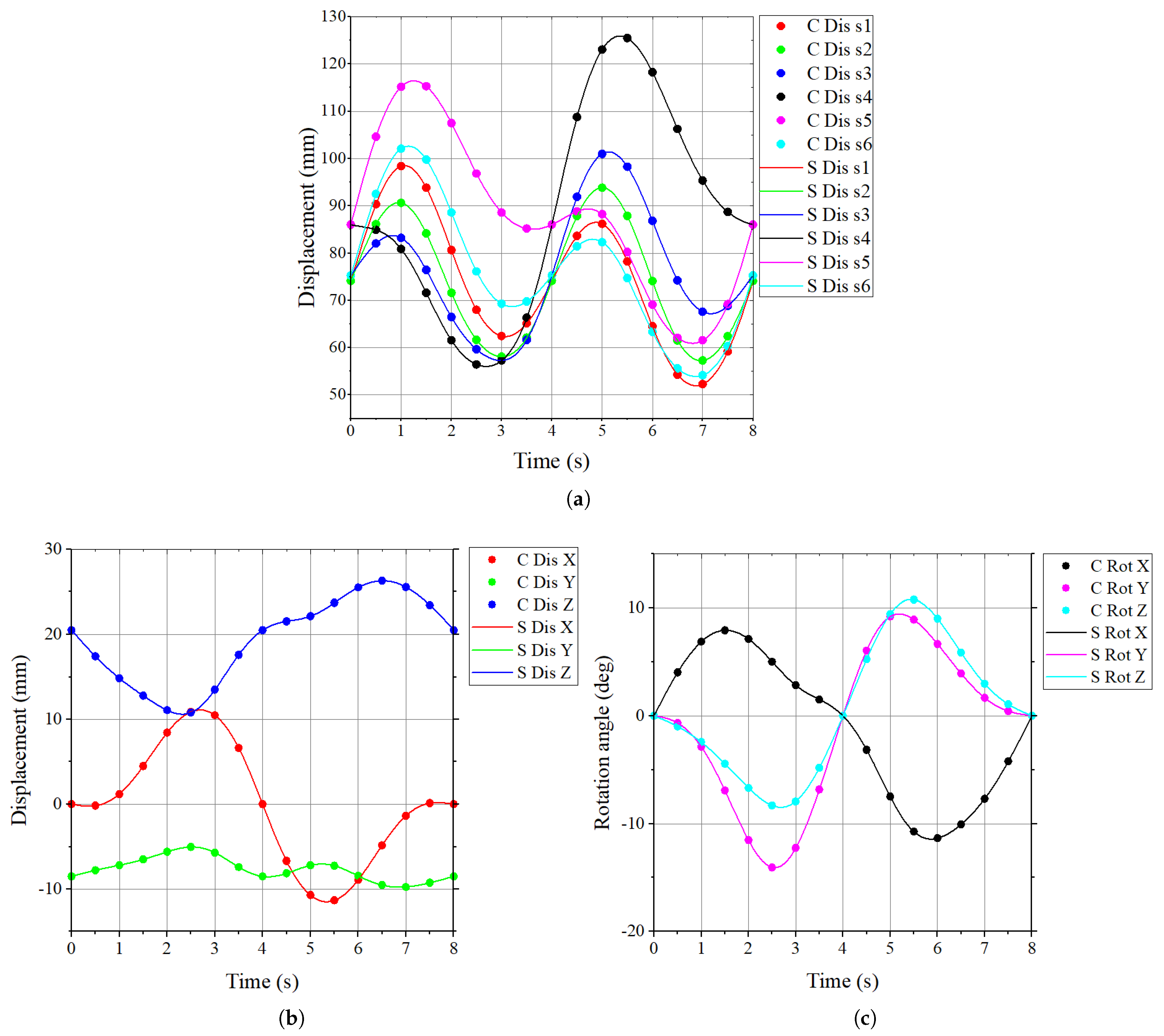
To verify the effectiveness of the proposed kinematic solution method, one example of inverse kinematics and one of forward kinematics is tested, as shown in Table 2. The kinematic theoretical model and the simulation model are compared to verify the correctness of the kinematic model and its solution. Figure 12 illustrates the kinematic simulation model of the needle motion control module, where appropriate motion constraints were added based on the kinematic pair types.
Figure 13 compares the numerical calculation results and the kinematic simulation results obtained for the kinematics examples. As shown in Figure 13, the numerical solutions match the ADAMS simulation results very well, thus validating the correctness of the inverse and forward kinematics algorithms.

4. Workspace Validation

The workspace of a robot is a major factor that affects its working performance. Because of the relatively large number of components involved in a parallel mechanism, the operation of this mechanism is more complex than those of serial robots or other parallel robots with fewer degrees of freedom. Some components may be subject to motion constraints, which lead to varying degrees of restriction on the robot’s workspace. Therefore, it is necessary to verify the workspace of the proposed blood sampling robot to ensure that it can operate without any motion interference while also meeting the operational requirements.

4.1. Factors Influencing the Workspace

To verify the robot’s workspace, it is essential to begin by understanding the key factors that influence it. For the blood sampling robot described in this paper, the three main factors influencing the workspace are given in the following:
1.
Constraint on slider travel. Because of the length limitations of the lead screw and the guide rail, the travel of the slider is constrained. Specifically, the slider displacement s i must satisfy s i m i n s i s i m a x , where s i m i n and s i m a x are the minimum and maximum displacements of the i-th slider, respectively. For the blood sampling robot described in this paper, s i m i n = 40 mm , s i m a x = 240 mm ( i = 1 , , 6 ) .
2.
Constraint on revolute pair angles. The rotation angle of the revolute pair is constrained by the structural limitations of the hinges, and there is a specific range within which the rotation angle can vary. If this range is exceeded, then motion interference may occur between the different components. In the case of the blood sampling robot described in this paper, the hinge points on the moving platform are more compact than those of conventional 6-DOF parallel robots. As a result, this motion interference may arise between adjacent offset hinges. It is difficult to use numerical methods to solve for the angular ranges of the hinges when such interference occurs. Therefore, a special pose simulation verification approach is used to ensure that the robot operates without interference within the required workspace.
3.
Motion interference constraint between components. During the movement of the robot’s active parts (e.g., the moving platform, the linkage, the end effector), interference with other components (e.g., the frame, the arm brackets) may occur. This interference can affect the working space. Like the constraints on the rotational angles, this constraint can also be validated through a special pose simulation verification approach.

4.2. Special Pose Calculation and Simulation Verification

When the range of human arm dimensions and the typical vascular distribution are combined with the structural dimensions of the blood sampling robot, the dexterous workspace required for the insertion of the blood sampling needle is defined as follows:
40 mm x 40 mm 28.5 mm y 8.5 mm 317.5 mm z 387.5 mm 10 α 10 30 β 30 10 γ 10
Additionally, because the blood collection needle must move from the initial position to the insertion point, the defined positional workspace for the needle when its attitude is α , β , γ T = [ 0 , 0 , 0 ] T is given as follows:
40 mm x 40 mm 8.5 mm y 11.5 mm 317.5 mm z 387.5 mm
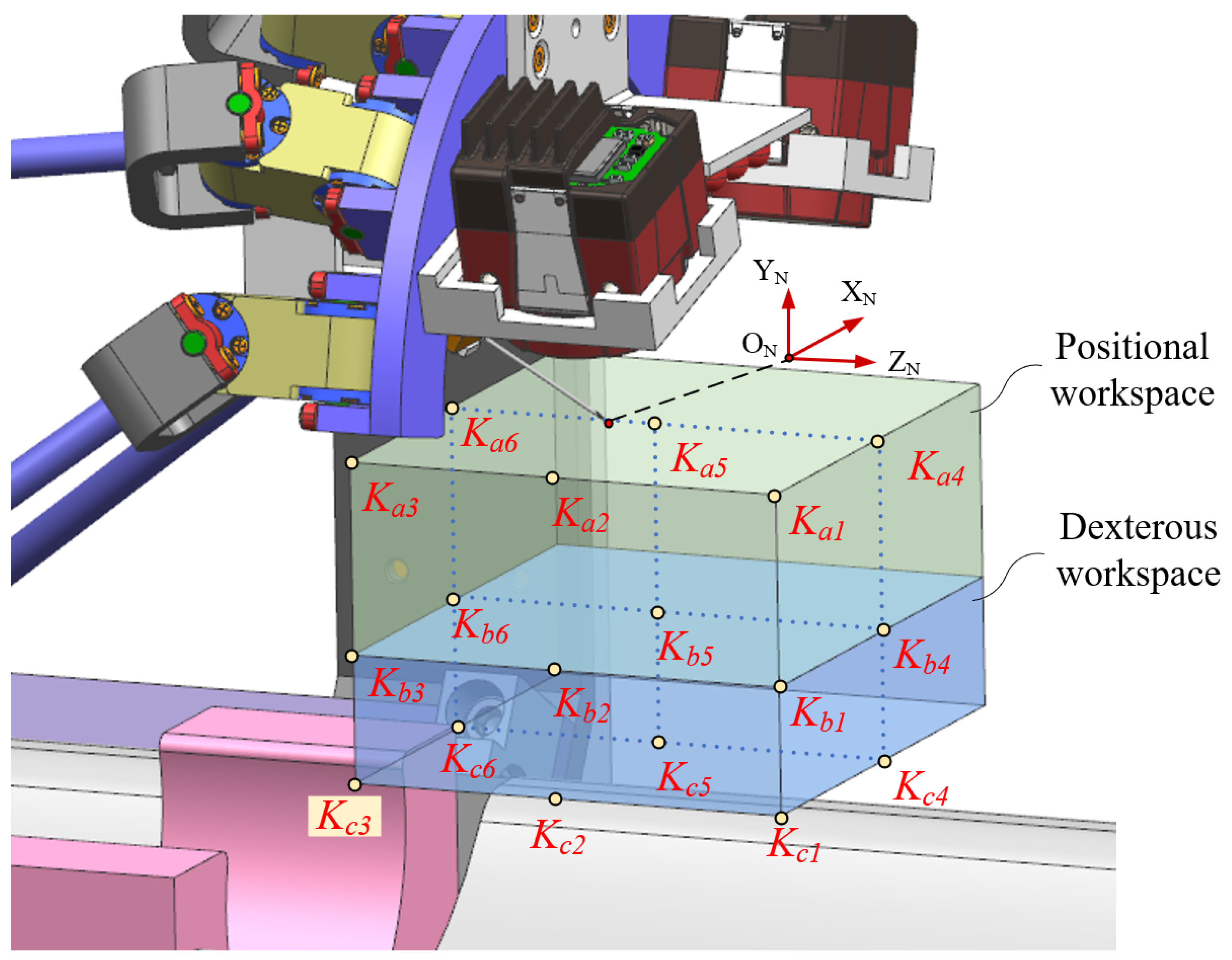
Next, special position points are selected from the workspace above. Because both the blood sampling robot and its workspace are symmetrical with respect to the plane Y B O B Z B , it is sufficient to select special position points from the half-space in which X B 0 , as shown in Table 3.
A schematic diagram of the workspace and the special points is shown in Figure 14.
For the six special position points K a i ( i = 1 , , 6 ) in the positional workspace, the needle tip O N of the blood sampling needle is required to coincide with each of these six points when the needle has the attitude [ α , β , γ ] T = [ 0 , 0 , 0 ] T . Using the inverse kinematic solution, we, therefore, check whether the displacement s i at each of these six postures meets the slider stroke constraints. Then, the clearance analysis is used to verify if any hard interference occurs within the robot when the needle is in these six poses.
For the 12 special position points K b i , K c i ( i = 1 , , 6 ) in the dexterous workspace, the needle tip O N is first aligned with the target special position point. For each position, the robot is then tested for eight extreme attitudes (as shown in Table 4). At each of these poses, the robot’s compliance with the slider stroke constraints and the absence of any hard interference are both verified. This process is conducted for all 12 special position points, with each position being tested at eight extreme attitudes, with a total of 96 poses to be checked as a result.
As an example, for one special pose p c 11 = x , y , z , α , β , γ T = 40 mm , 28.5 mm , 387.5 mm , 10 , 30 , 10 T , the value of s i can be calculated first using inverse kinematics as
s 1 s 2 s 3 s 4 s 5 s 6 = 215.6387357493143 mm 215.5492832574431 mm 199.4526524544910 mm 196.1337613631630 mm 200.3508668919566 mm 213.8296436561934 mm
The calculation results show that the condition s i m i n s i s i m a x is met for this pose. After a clearance analysis, the results indicate that there is no hard interference. The robot model at this posture is illustrated in Figure 15.
Using the same method, the displacement constraints of the sliders and the motion interference analysis are verified for a total of 102 postures within both the dexterous workspace and the positional workspace. The results all met the constraint requirements.

5. Accuracy Test

The accuracy of the robot’s motion is one of the most important indicators for an evaluation of its overall performance. In this work, the translational and rotational motion accuracy characteristics of the needle control module in the blood sampling robot are tested experimentally to provide further validation of the reliability of the robot.

5.1. Test System Construction

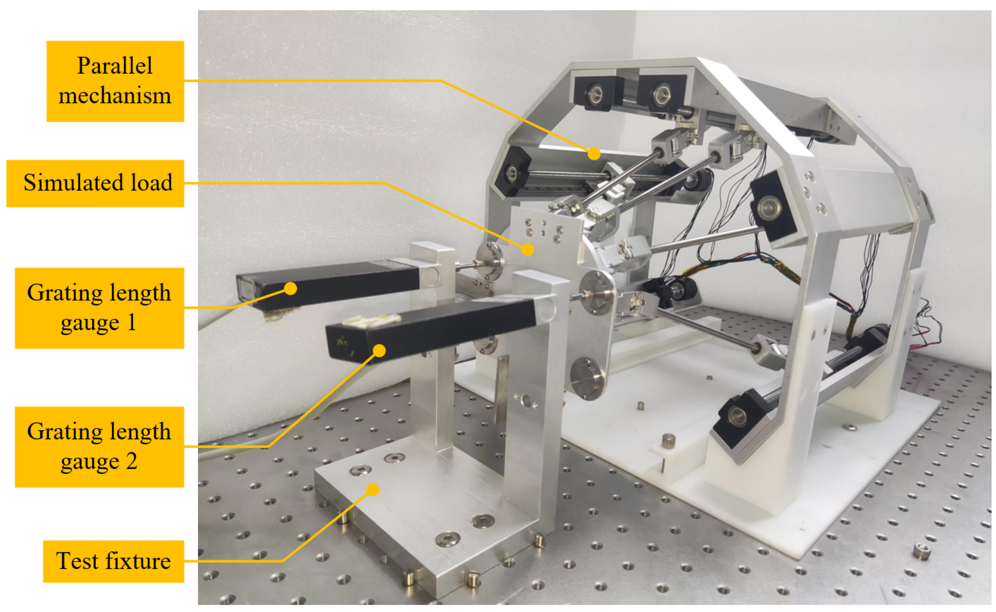
The test system mainly consists of a test fixture, a simulated load, the parallel mechanism under test (i.e., the needle motion control module), and the grating length gauges, as shown in Figure 16. The test zero position is taken to be x , y , z , α , β , γ T = [ 0 mm , 18.5 mm , 352.5 mm , 0 , 0 , 0 ] T , and then the translational motion accuracy is tested along the Z-direction. The rotational motion accuracy is tested around the Y-axis. The schematic diagram of the test is shown in Figure 17. The translational displacement along the Z-axis is defined as T Z , and the length variations of the grating scales 1 and 2 are denoted by l 1 and l 2 , respectively. Therefore, T Z can be expressed as a function of l 1 and l 2 as follows:
T Z = l 1 + l 2 2
The rotational angle around the Y-axis is defined as R Y , and R Y can also be expressed as a function of l 1 and l 2 , as follows:
R Y = arctan l 1 l 2 2 d

5.2. Motion Accuracy Testing

The motion accuracy is measured using a fixed step length and a multi-point cyclic measurement approach [30].
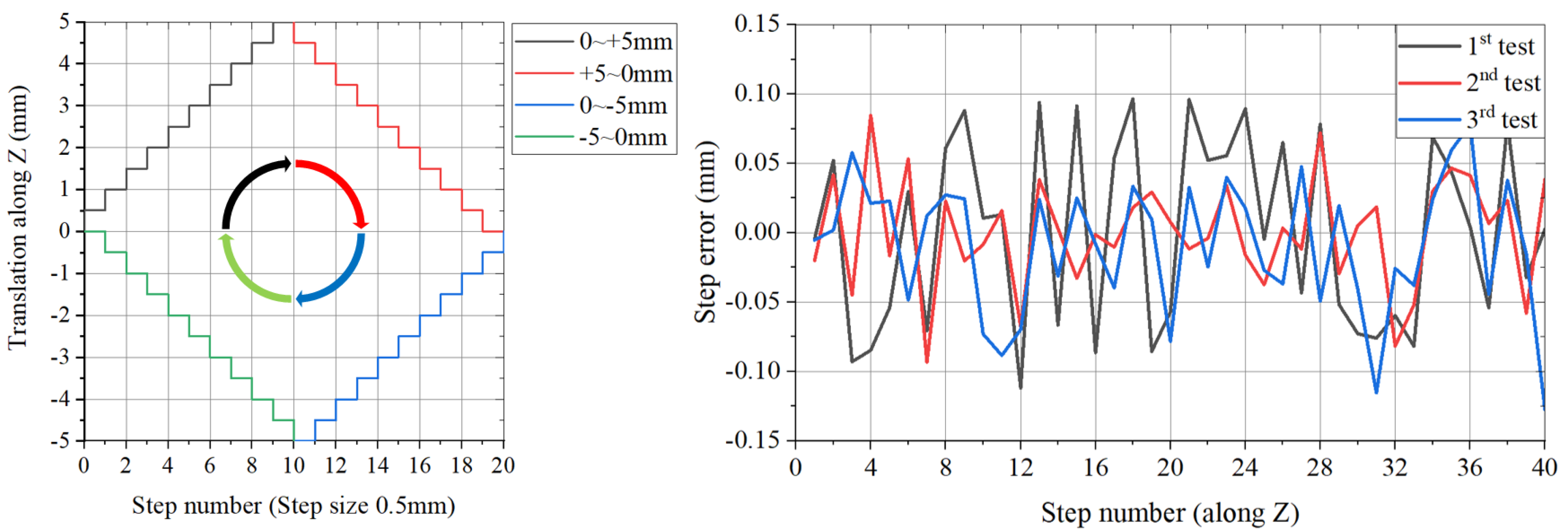
In the translational motion accuracy test, measurements are taken along the Z-axis translation direction within the range from 5 mm to + 5 mm using a step size of 0.5 mm . The test is conducted using the sequence from 0 mm + 5 mm 0 mm 5 mm 0 mm for three cycles. The test results are shown in Figure 18.
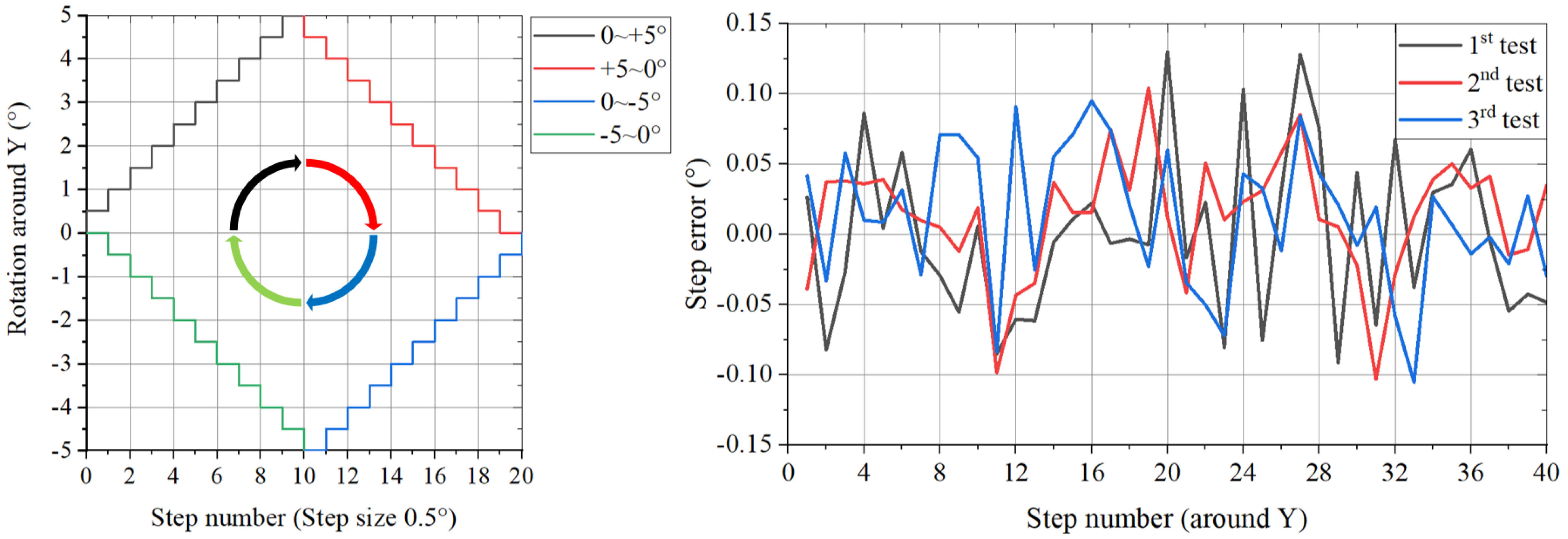
In the rotational accuracy test, the rotation is performed around the Y-axis. The test is conducted within the range from 5 to + 5 using a step size of 0 . 5 , and it follows the sequence 0 + 5 0 5 0 for three cycles. The test results are shown in Figure 19.
After the measured data in Figure 18 and Figure 19 are processed, the step accuracy of the translational along the Z-direction is 0.05172 mm, and the step accuracy of the rotational around the Y-axis is 0 . 05099 .

6. Conclusions and Future Work

This paper presents the design for a kind of portable robot for venous blood sampling and conducts kinematics and workspace analyses and verifications. First, based on the manual blood sampling process and modular design concepts, the structural design of the entire robot and its individual modules was completed. To address the problem of the limited workspace for the parallel mechanism, an offset RR-hinge structure was introduced into the needle control module. Next, a kinematic analysis of the 6-P-RR-R-RR horizontal parallel mechanism used for the needle control module was conducted. Because of the introduction of new offset parameters, the kinematics of the mechanism is more complex than that of conventional 6-DOF parallel mechanisms. The work in this paper used the kinematic constraint characteristics of the offset hinge to establish the kinematic mathematical model of the mechanism. The nonlinear equations derived in this kinematic model were solved via the Newton–Raphson numerical iterative method. Subsequently, comparing numerical calculation results with simulation results were performed to validate the correctness of the kinematic model and the solutions obtained. To prove the robot’s workspace meets the requirements for blood sampling, special poses within the given workspace were computed and verified through simulations. Finally, a test system was constructed for the 6-P-RR-R-RR horizontal parallel mechanism, and the translational and rotational step accuracies of the mechanism were tested.
Compared with existing blood sampling robots, the blood sampling robot designed in this paper greatly reduces the size of the equipment, making it easier to carry, and its accuracy meets the requirements required for blood sampling. Table 5 selects three kinds of existing blood sampling robots to compare with the blood sampling robot designed in this paper.
For future work, the next phase will design and verify the vein recognition algorithm of the venous imaging module and the puncture sensing algorithm of the puncture sensing module and add the puncture point decision algorithm. The third phase will carry out a comprehensive design of other subsystems of the robot, including a disinfection subsystem, needle replacement subsystem, human–computer interaction subsystem, hemostatic subsystem, and safety protection subsystem. In the final stage, more real human experiments will be conducted to obtain more detailed experimental data to verify and improve the reliability of the blood sampling robot.

Author Contributions

Conceptualization, H.X. and H.H.; methodology, H.X. and H.H.; software, H.X., G.M. and P.Y.; validation, H.X. and H.H.; formal analysis, H.X.; investigation, H.X. and Z.F.; resources, H.H. and Z.X.; data curation, H.X. and Z.F.; writing—original draft preparation, H.X.; writing—review and editing, H.X. and H.H.; visualization, H.X.; supervision, H.X.; project administration, H.X. and H.H.; funding acquisition, H.H. All authors have read and agreed to the published version of the manuscript.

Funding

This work was supported by the Youth Innovation Promotion Association, Chinese Academy of Sciences [Grant No. 2022215], and the National Natural Science Foundation of China [Grant No. 62235018].

Data Availability Statement

Data are contained within the article.

Conflicts of Interest

The authors declare no conflicts of interest.

References

  1. Kidd, B.A.; Hoffman, G.; Zimmerman, N.; Li, L.; Morgan, J.W.; Glowe, P.K.; Botwin, G.J.; Parekh, S.; Babic, N.; Doust, M.W.; et al. Evaluation of direct-to-consumer low-volume lab tests in healthy adults. J. Clin. Investig. 2016, 126, 2773. [Google Scholar] [CrossRef]
  2. Lillis, K.A.; Jaffe, D.M. Prehospital intravenous access in children. Ann. Emerg. Med. 1992, 21, 1430–1434. [Google Scholar] [CrossRef] [PubMed]
  3. Fu, X.; Jiang, H. Current situation of medical resource allocation and service utilization in Chinese hospitals based on structural change analysis. Mod. Hosp. 2024, 24, 664–669+673. [Google Scholar]
  4. Katsogridakis, Y.L.; Seshadri, R.; Sullivan, C.; Waltzman, M.L. Veinlite transillumination in the pediatric emergency department—A therapeutic interventional trial. Pediatr. Emerg. Care 2008, 24, 83–88. [Google Scholar] [CrossRef]
  5. Xiong, X.; Xiong, Y.L.; Liu, G.F. Systematic review and meta-analysis: Safety of ultrasound-guided peripheral venipuncture and catheterization. Ann. Pallliat. Med. 2021, 10, 11721–11732. [Google Scholar] [CrossRef]
  6. Dreyer, J.; Huenges, K.; Cremer, J.; Haneya, A. A new device for vein localization and effect of application of disinfectant spray on its efficiency. Curr. Dir. Biomed. Eng. 2017, 3, 127–130. [Google Scholar] [CrossRef]
  7. Zivanovic, A.; Davies, B.L. A robotic system for blood sampling. IEEE Trans. Inf. Technol. Biomed. 2000, 4, 8–14. [Google Scholar] [CrossRef] [PubMed]
  8. Kudashov, I.; Shchukin, S.; Al-harosh, M.; Shcherbachev, A. Smart Bio-Impedance-Based Sensor for Guiding Standard Needle Insertion. Sensors 2022, 22, 665. [Google Scholar] [CrossRef]
  9. Perry, T.S. Profile: Veebot drawing blood faster and more safely than a human can. IEEE Spectr. 2013, 50, 23. [Google Scholar] [CrossRef]
  10. Fang, X. MagicNurse: “AI+ Medical” to create a fully automatic intelligent blood collection Magic Nurse. Robot Ind. 2021, 2, 56–60. [Google Scholar]
  11. Kim, S.; Choi, S.; Yeom, K. Design and development of robotic system for precise vascular access and autonomous venipuncture. Electron. Lett. 2024, 60, e13121. [Google Scholar] [CrossRef]
  12. Choi, S.; Kim, S.; Yeom, K. An injection-point determination algorithm for intelligent injection robot systems. IEICE Electron. Express 2024, 21, 20230283. [Google Scholar] [CrossRef]
  13. Uchiyama, M. Structures and characteristics of parallel manipulators. Adv. Robot. 1994, 8, 545–557. [Google Scholar] [CrossRef]
  14. Shoham, M.; Burman, M.; Joskowicz, L.; Batkilin, E.; Kunicher, Y. Bone-mounted miniature robot for surgical procedures: Concept and clinical applications. IEEE Trans. Robot. Autom. 2013, 19, 893–901. [Google Scholar] [CrossRef]
  15. Nakano, T.; Sugita, N.; Ueta, T.; Tamaki, Y.; Mitsuishi, M. A parallel robot to assist vitreoretinal surgery. Int. J. Comput. Assist. Radiol. Surg. 2009, 4, 517–526. [Google Scholar] [CrossRef]
  16. Gough, V.E. Contribution to discussion to papers on research in automobile stability and control and in tire performance. Proc. Automot. Div. Inst. Mech. Eng. 1957, 180, 392–394. [Google Scholar]
  17. Stewart, D. A platform with six degrees of freedom. Proc. Inst. Mech. Eng. C. J. Mech. Eng. Sci. 1965, 180, 371–386. [Google Scholar] [CrossRef]
  18. Seide, K.; Wolter, D.; Kortmann, H.R. Fracture reduction and deformity correction with the hexapod Ilizarov fixator. Clin. Orthop. Relat. Res. 1999, 10, 186–195. [Google Scholar] [CrossRef]
  19. Takemura, H.; Onodera, T.; Ming, D.; Mizoguchi, H. Design and Control of a Wearable Stewart Platform-Type Ankle-Foot Assistive Device Regular Paper. Int. J. Adv. Robot. Syst. 2012, 9, 202–208. [Google Scholar] [CrossRef]
  20. Grossmann, K.; Kauschinger, B. Eccentric universal joints for parallel kinematic machine tools: Variants and kinematic transformations. Prod. Eng.-Res. Dev. 2012, 6, 521–529. [Google Scholar] [CrossRef]
  21. Hu, B.; Lu, Y. Analyses of kinematics, statics, and workspace of a 3-RR(P)under-barRR parallel manipulator and its three isomeric mechanisms. Proc. Inst. Mech. Eng. Part C-J. Eng. Mech. Eng. Sci. 2008, 222, 1829–1837. [Google Scholar] [CrossRef]
  22. Li, P.Y.; Han, H.; Liu, C.L.; Ren, B.; Wu, Q.W.; Xu, Z.B. Workspace analysis of axial offset joint based on parameterization. Robotica 2023, 41, 2882–2906. [Google Scholar] [CrossRef]
  23. Ji, P.; Wu, H.T. Kinematics analysis of an offset 3-UPU translational parallel robotic manipulator. Robot. Auton. Syst. 2023, 42, 117–123. [Google Scholar] [CrossRef]
  24. Cai, Z.X.; Xie, B. Robotics, 3rd ed.; Tsinghua University Press: Beijing, China, 2015; pp. 45–46. [Google Scholar]
  25. Dalvand, M.M.; Shirinzadeh, B. Kinematics analysis of 6-DOF parallel micro-manipulators with offset U-joints: A case study. Int. J. Intell. Mechatron. Robot. 2012, 2, 28–40. [Google Scholar] [CrossRef]
  26. Zhang, Y.; Han, H.; Xu, Z.B.; Han, C.Y.; Yu, Y.; Mao, A.L.; Wu, Q.W. Kinematics analysis and performance testing of 6-RR-RP-RR parallel platform with offset RR-hinges based on Denavit-Hartenberg parameter method. Proc. Inst. Mech. Eng. Part C-J. Eng. Mech. Eng. Sci. 2021, 235, 3519–3533. [Google Scholar] [CrossRef]
  27. Morell, A.; Tarokh, M.; Acosta, L. Solving the forward kinematics problem in parallel robots using Support Vector Regression. Eng. Appl. Artif. Intell. 2013, 26, 1698–1706. [Google Scholar] [CrossRef]
  28. Ogden-Grable, H.; Gill, G.W. Phlebotomy puncture juncture—Preventing phlebotomy errors—Potential for harming your patients. Lab. Med. 2005, 36, 430–433. [Google Scholar] [CrossRef]
  29. China NHCotPsRo. Guidelines of venous blood specimen collection. Chin. Pract. J. Rural. Dr. 2020, 27, 7–11. [Google Scholar]
  30. GB/T12642; Industrial Robots—Performance Criteria and Related Test Methods. AQSIQ, SAC: Beijing, China, 2013.
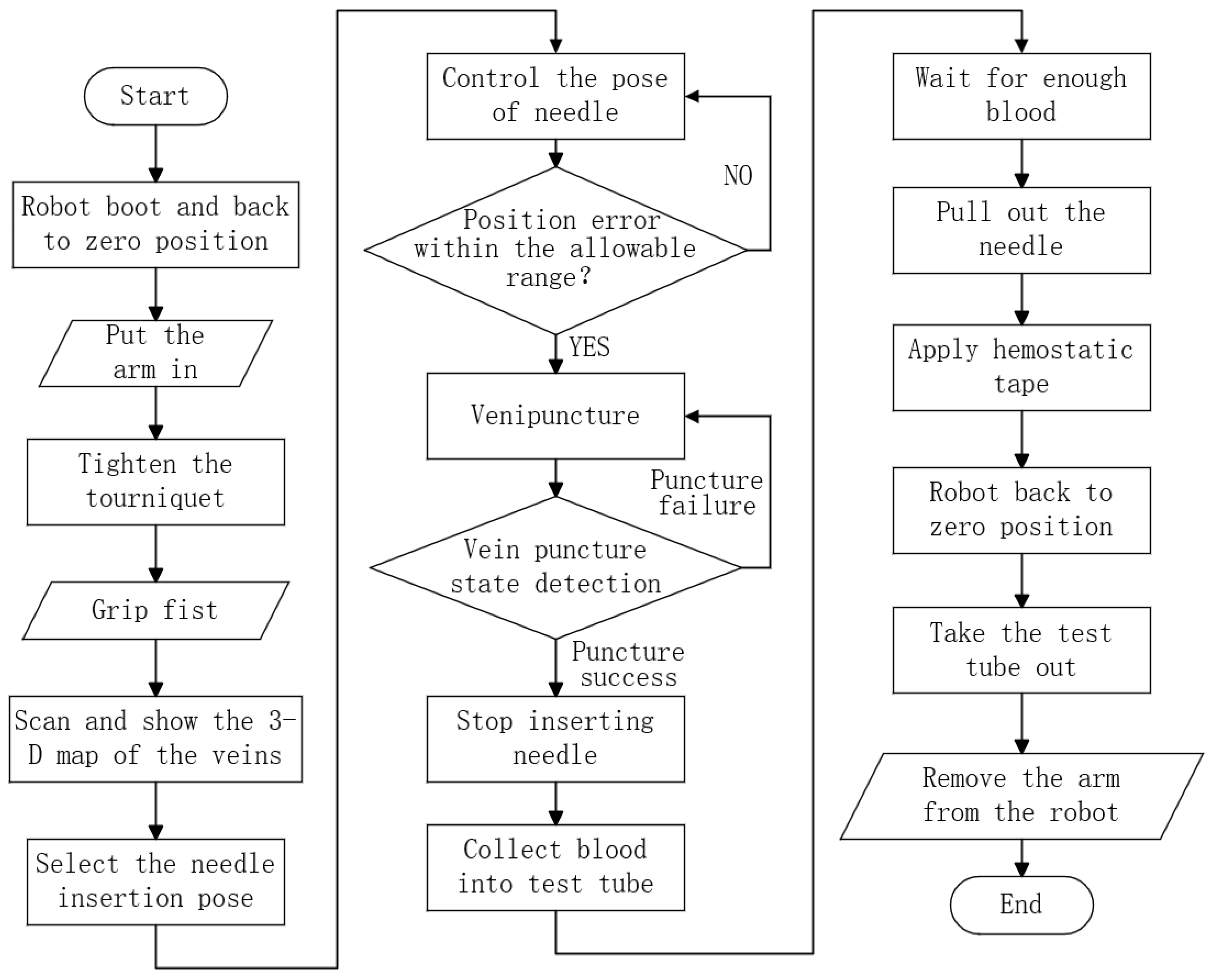
Figure 1. Venous blood sampling robot workflow.
Machines 13 00203 g001
Figure 2. Three-dimensional model of complete machine and each function module: (a) complete machine, (b) needle motion control module, (c) blood collection module, (d) arm support module, (e) venous imaging module, and (f) puncture sensing module.
Machines 13 00203 g002
Figure 3. 6-P-RR-R-RR horizontal parallel mechanism schematic.
Machines 13 00203 g003
Figure 4. Leg structure.
Machines 13 00203 g004
Figure 5. Interaction and workflow between each module.
Machines 13 00203 g005
Figure 6. P-RR-R-RR legs kinematic chain.
Machines 13 00203 g006
Figure 7. Upper and lower joint point distributions.
Machines 13 00203 g007
Figure 8. The upper and lower joint point conjoined coordinate system: (a) local coordinate system of upper joint point and (b) local coordinate system of lower joint point.
Machines 13 00203 g008
Figure 9. Kinematic constraints of the offset hinge.
Machines 13 00203 g009
Figure 10. Inverse kinematics solution flowchart.
Machines 13 00203 g010
Figure 11. Forward kinematics solution flowchart.
Machines 13 00203 g011
Figure 12. Kinematic simulation model.
Machines 13 00203 g012
Figure 13. Comparison of kinematic numerical calculation and simulation results (C—numerical calculation results, S—simulation results, Dis—translational displacement, Rot—rotational angle): (a) inverse kinematics result, (b) forward kinematic displacement result, and (c) forward kinematic rotation angle result.
Machines 13 00203 g013
Figure 14. Workspace and the special points.
Machines 13 00203 g014
Figure 15. Schematic of the model at pose p c 11 .
Machines 13 00203 g015
Figure 16. Test system configuration.
Machines 13 00203 g016
Figure 17. Schematic diagram of the test.
Machines 13 00203 g017
Figure 18. Translation accuracy test results measured along the Z-axis.
Machines 13 00203 g018
Figure 19. Rotational accuracy test results around the Y-axis.
Machines 13 00203 g019
Table 1. Parallel mechanism structural parameters.
r P / mm r B / mm θ P / θ B 1 / θ B 2 / u / mm l / mm ( x N , y N , z N ) / mm
5512531153020170(0, 8.5 , 20.5)
Table 2. Inverse and forward kinematics simulation examples.
Prescribed Motion of the Needle
(for Inverse Kinematics)
Prescribed Motion of the Sliders
(for Forward Kinematics)
x N = 15 · sin ( 0.25 π t ) ( mm ) s 1 = 74.0946 + 2 · sin ( 0.25 π t ) ( mm )
y N = 8.5 10 · sin ( 0.25 π t ) ( mm ) s 2 = 74.0946 + 1.5 · sin ( 0.25 π t ) cos ( 0.25 π t ) ( mm )
z N = 292.5 + 8 · sin ( 0.25 π t ) · cos ( 0.25 π t ) ( mm ) s 3 = 75.2689 + 0.4 · sin ( 0.25 π t ) ( mm )
α = 0.5 · sin ( 0.25 π t ) · cos ( 0.25 π t ) ( ) s 4 = 86.0282 + sin ( 0.25 π t ) · cos ( 0.25 π t ) ( mm )
β = 0.5 · sin ( 0.25 π t ) ( ) s 5 = 86.0282 + 0.3 · sin ( 0.25 π t ) ( mm )
γ = 0.25 · sin ( 0.25 π t ) ( ) s 6 = 75.2689 + sin ( 0.25 π t ) · cos ( 0.25 π t ) ( mm )
0 t 8 ( s ) 0 t 8 ( s )
Table 3. Special position point coordinates (mm).
K ai ( i = 1 , , 6 ) K bi ( i = 1 , , 6 ) K ci ( i = 1 , , 6 )
K a 1 ( 40 , 11.5 , 387.5 ) K b 1 ( 40 , 8.5 , 387.5 ) K c 1 ( 40 , 28.5 , 387.5 )
K a 2 ( 40 , 11.5 , 352.5 ) K b 2 ( 40 , 8.5 , 352.5 ) K c 2 ( 40 , 28.5 , 352.5 )
K a 3 ( 40 , 11.5 , 317.5 ) K b 3 ( 40 , 8.5 , 317.5 ) K c 3 ( 40 , 28.5 , 317.5 )
K a 4 ( 40 , 28.5 , 387.5 ) K b 4 ( 0 , 8.5 , 387.5 ) K c 4 ( 0 , 28.5 , 387.5 )
K a 5 ( 40 , 28.5 , 352.5 ) K b 5 ( 0 , 8.5 , 352.5 ) K c 5 ( 0 , 28.5 , 352.5 )
K a 6 ( 40 , 28.5 , 317.5 ) K b 6 ( 0 , 8.5 , 317.5 ) K c 6 ( 0 , 28.5 , 317.5 )
Table 4. Eight extreme attitudes [ α , β , γ ] .
  α > 0 , β > 0 α > 0 , β < 0 α < 0 , β > 0 α < 0 , β < 0
γ > 0 [ 10 , 30 , 10 ] [ 10 , 30 , 10 ] [ 10 , 30 , 10 ] [ 10 , 30 , 10 ]
γ < 0 [ 10 , 30 , 10 ] [ 10 , 30 , 10 ] [ 10 , 30 , 10 ] [ 10 , 30 , 10 ]
Table 5. Blood sampling robots comparison.
RobotVeebotMagicNurseVeniBotThis Paper
Structure typeSeriesSeriesSeriesParallel
  Monocular NIR imagingMonocular NIR imagingBinocular NIR imaging
Sense scheme+US imaging+US imaging+Puncture force detection
    +Blood flow back detection
Size (mm)AboutAboutAbout390 × 378 × 325
 1500 × 1000 × 10001500 × 1500 × 1500600 × 600 × 600 
Portability××
AccuracyHighHighLowMedium
Disclaimer/Publisher’s Note: The statements, opinions and data contained in all publications are solely those of the individual author(s) and contributor(s) and not of MDPI and/or the editor(s). MDPI and/or the editor(s) disclaim responsibility for any injury to people or property resulting from any ideas, methods, instructions or products referred to in the content.