1. Introduction
Through a long history of natural selection, organisms have evolved a wide variety of efficient locomotion strategies [
1,
2]. These locomoting mechanisms endow organisms with essential survival behaviors such as foraging, escaping, and navigating. Autonomous locomotion, the behavior that most dictates the morphological and physiological evolution, enables organisms to survive in and adapt to complex, severe environments [
3,
4]. The efficiency and elegance of animal motion have inspired scientists and engineers to design advanced materials [
5,
6,
7], innovative structures [
8,
9,
10], and functional devices [
11,
12,
13]. Among all evolutionary forms of locomotion, fish swimming represents one of the most refined outcomes. Their highly efficient, adaptable, and maneuverable movements provide exceptional insights for the design of bionic robotic systems [
14].
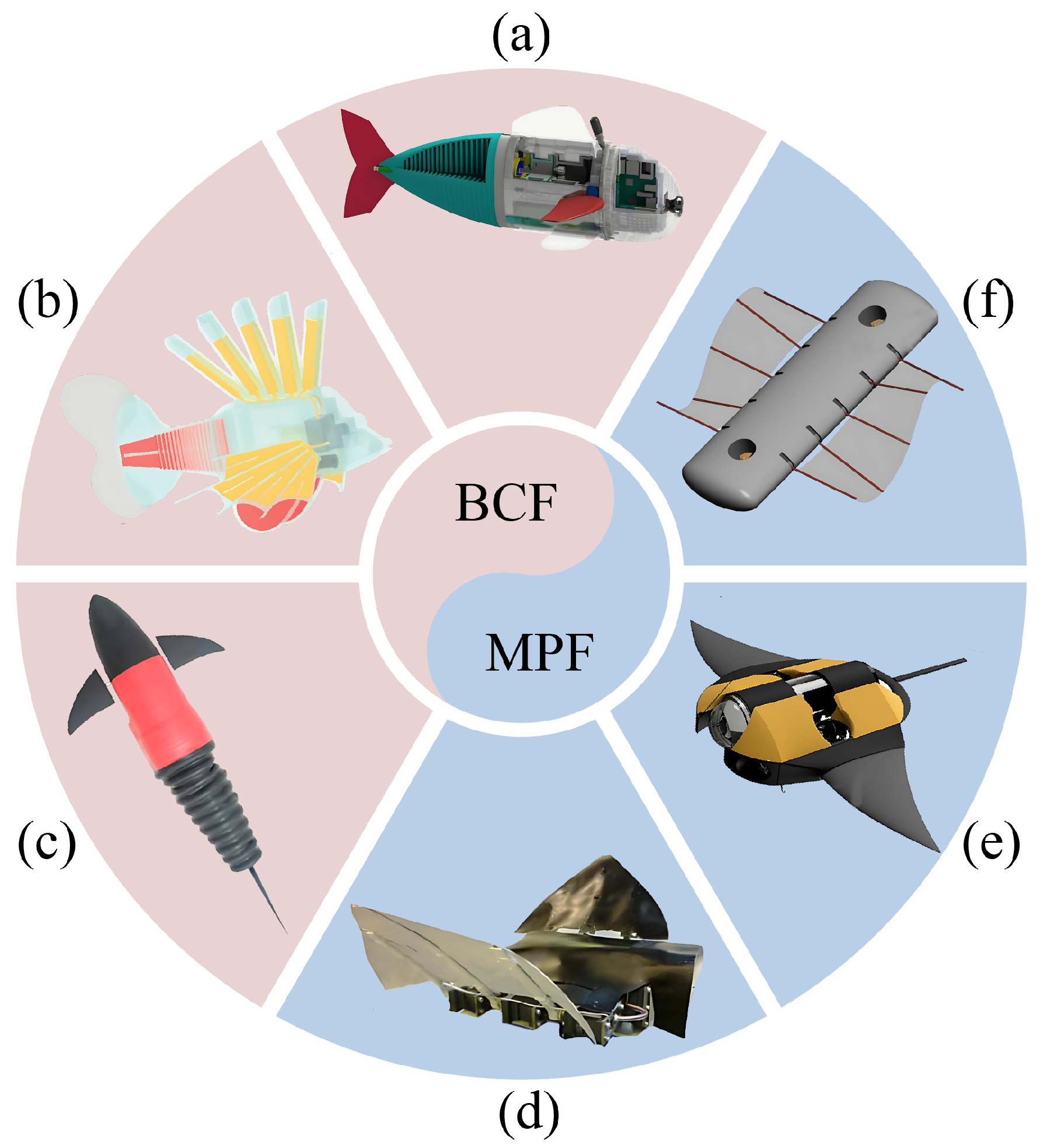
Based on the propulsive mechanism, the locomotion of fish can be classified into two main categories: body and/or caudal fin (BCF) propulsion, and median and/or paired fin (MPF) propulsion [
15,
16]. In BCF swimming, thrust is generated through the asymmetrical interaction between the undulatory or oscillatory body and the surrounding water (
Figure 1a–c). This propulsion mechanism is especially advantageous for high-speed and long-distance swimming, which is adopted by species, e.g., tunas and sharks [
17]. However, it usually exhibits reduced efficiency at low speeds and offers limited maneuverability [
18]. In contrast, MPF propulsion relies mainly on the undulatory or oscillatory motion of the pectoral or median fins (
Figure 1d–f). This strategy, adopted by such as stingrays, skates, and many reef fish, is characterized by precise control, high stability, and efficient movement at low to moderate speeds [
19]. It is also effective in complex and confined underwater environments [
20].
The advantages of MPF propulsion, including high efficiency, superb stealthiness, and excellent maneuverability, make it suitable for robotic applications that require long-term operation [
27,
28]. By adopting a kind of soft electrohydraulic actuator, a manta ray-inspired robotic fish was developed [
29]. The underwater flapping motion of the two pectoral fins enabled the robot to realize fast and stable MPF propulsion. Based on the virtue of the modular and reconfigurable design concept, an undulatory fin propulsion prototype was developed [
30]. Swimming tests showed that the robotic stingray can achieve a maximum speed of 0.46 m/s with an undulatory frequency of 1.67 Hz. However, most existing designs require multiple actuators and complex mechanical systems with numerous gears or linkages to reproduce the undulatory fin motion. Such complexity not only increases the body weight, fabrication cost, and energy consumption, but also reduces the reliability and endurance of the robotic fish.
Structural instability is ubiquitous in living systems, manifesting in diverse forms across nano [
31,
32], micro [
33], meso [
34,
35], and macro scales [
36,
37]. These instability-induced morphological evolutions of biological structures have inspired the design of high-performance systems such as soft robots [
38,
39] and energy harvesting devices [
40,
41,
42,
43]. Based on the local snap-through buckling of a ring, a rolling soft robot was developed [
44]. This robot exhibits high locomotion speed and low energy loss owing to its almost unchanged configuration during rolling. By harnessing the snapping-induced flapping and rotation of multistable flexible wings, a soft flapping-wing swimmer was developed, which can achieve high-speed, efficient, and maneuverable swimming [
45]. However, the pneumatic actuation mechanism makes these robots bulky and heavy, which limits their practical applications. More recently, based on the periodic, reversible mechanical deformation of flexible rods and films, Zhao et al. [
46] designed an untethered, soft robotic ray driven by a dynamoelectric motor. While the structure of the robot is simplified and its energy consumption is reduced, the swimming speed remains relatively low and the maneuverability is limited due to the single-actuator design.
In this paper, inspired by the elegant swimming gait of
Potamotrygon motoro, we develop a soft robotic fish driven by two dynamoelectric motors, which can realize highly efficient, controllable directional propulsion and excellent underwater maneuverability through the undulatory motion of the pectoral fins. The snap-through instability of elastic curved rods is utilized in the robot to generate the undulatory fin motion. This paper is organized as follows.
Section 2 presents the details of the design scheme, numerical simulation, theoretical prediction, and experimental measurement. In
Section 3, we analyze the buckling morphology of the torsional rod, the propulsion performance, and the maneuverability of the robotic fish. In
Section 4, the swimming capability and the potential application of the robotic fish are discussed. Finally, the main conclusions are summarized in
Section 5.
2. Materials and Methods
This section begins with an introduction to the robotic fish structure. Subsequently, numerical simulation and experimental measurement are combined to analyze the morphological evolution of a torsional rod. Due to the structural symmetry, only one elastic rod is examined. Then, a theoretical model is established to predict the propulsive force of the robot. Finally, the swimming tests for propulsion and maneuverability evaluations are presented.
2.1. Design and Fabrication
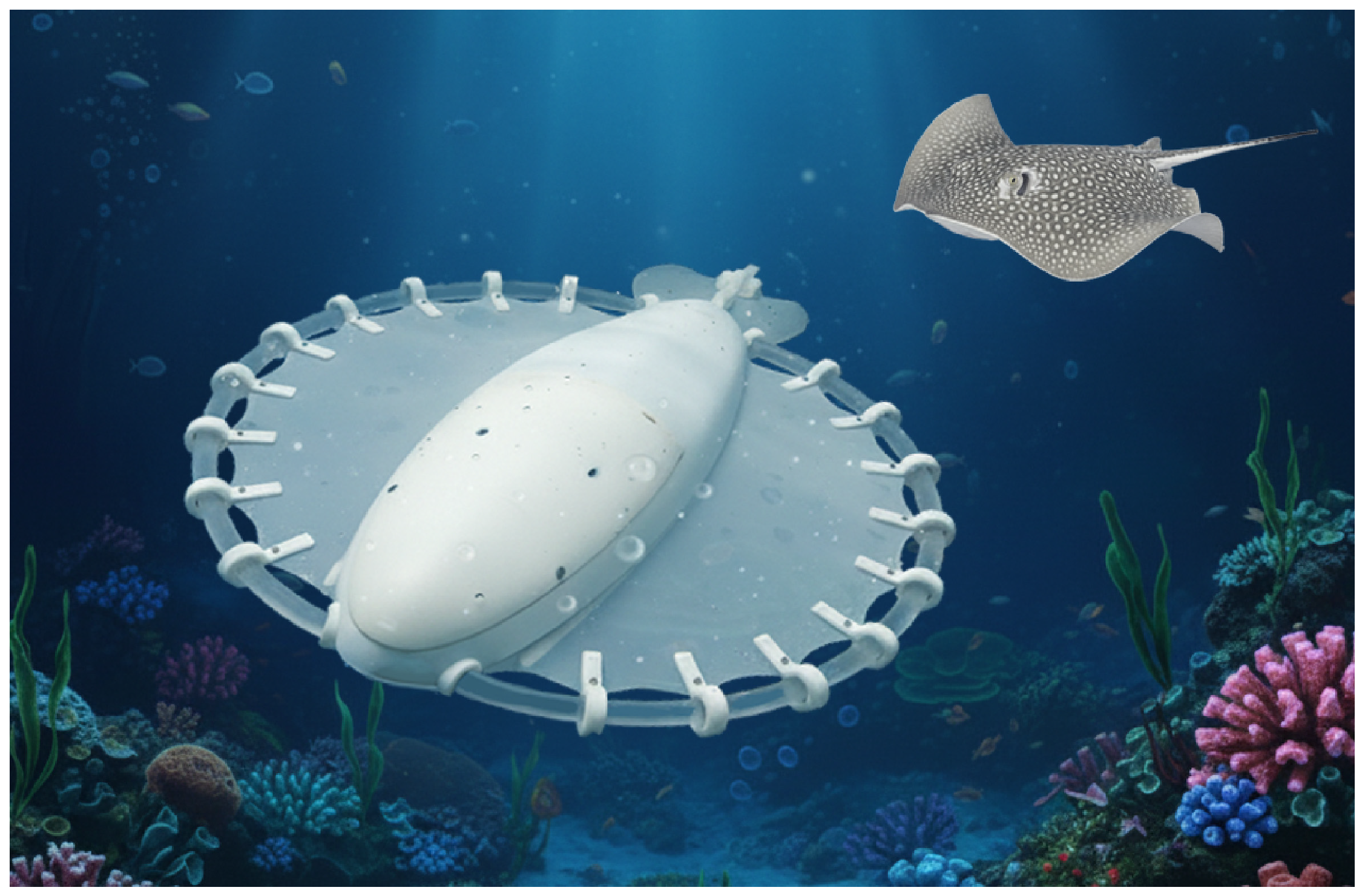
As illustrated in
Figure 2, the fin disk of a swimming
Potamotrygon motoro exhibits a distinctive wave-like rim. Inspired by this graceful swimming stroke, we develop a robotic fish, where the snap-through instability of elastic curved rods is employed to generate the undulatory fin motion.
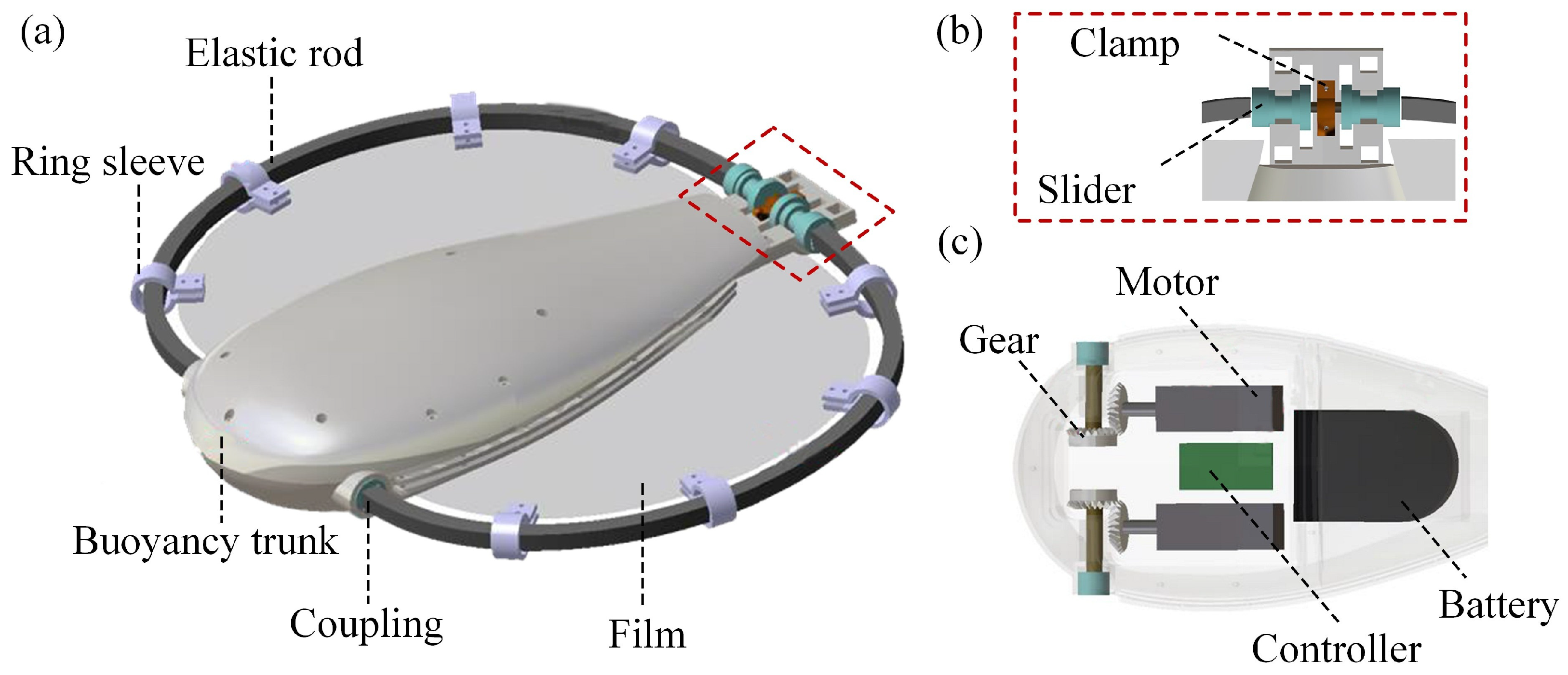
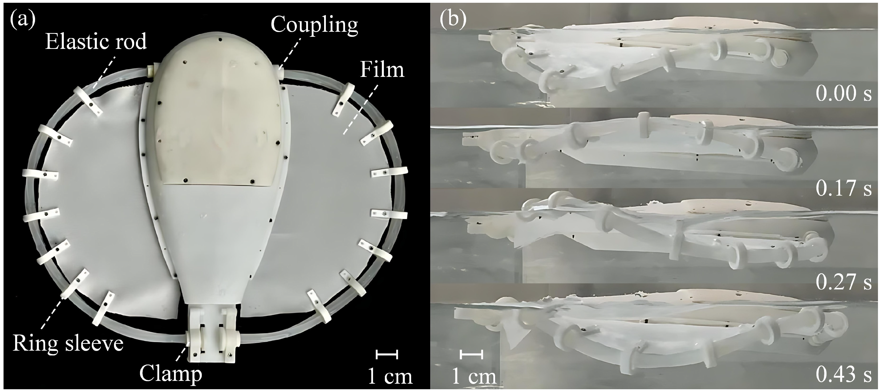
Figure 3a presents the main components of the robot, e.g., a streamlined buoyancy trunk, two elastic rods, two pieces of flexible film, several ring sleeves, and a rigid coupling. One end of the elastic rod is connected to the motor shaft through the coupling and the other end is connected to the slider (
Figure 3b). Ring sleeves are used to connect the rod to the film, which are evenly distributed along the fin rim. The driving devices and controlling circuits are mounted on the trunk (
Figure 3c). The driving devices include the gears and motors (GA12-N20, Shenzhen Xinhaitong Electric Machinery Factory, Shenzhen, China). The controlling circuits consist of a battery (402030, Chuangli New Energy Co., Ltd., Yongzhou, China) and a controller (WY-HW-0007, Wenyuan Electronics Co., Ltd., Shenzhen, China).
As the driving end rotates, the friction between the slider and the clamp gradually increases; beyond a critical value, the releasing end begins to rotate. The elastic strain energy of the rod is stored and released alternately. The swimming motion of the robotic fish is controlled by adjusting the motor speed through a wireless remote-control system. Turning maneuvers are realized by independently controlling the two motors.
The trunk, ring sleeve, slider, and clamp are fabricated using a 3D printer (Raise 3D Pro2 Plus, Raise3D Technologies, Inc., Shanghai, China). The rods are made of silica gel, with a square cross-section. The films are made of waterproof fabric. The overall robotic fish measures approximately 17 cm in length and 20 cm in width. The direct current gear motor is powered by a 200 mAh rechargeable lithium battery. The rated voltage and current of the motor are 3 V and 0.2 A, respectively.
2.2. Numerical Simulation
When subjected to a torsional displacement under specific constraints, the elastic rod may undergo a distinct snap-through instability, followed by spontaneous recovery to its original configuration. The dynamic-implicit solver in Abaqus (Version 2020) is adopted to calculate the morphological evolution of the rod and the pectoral fin.
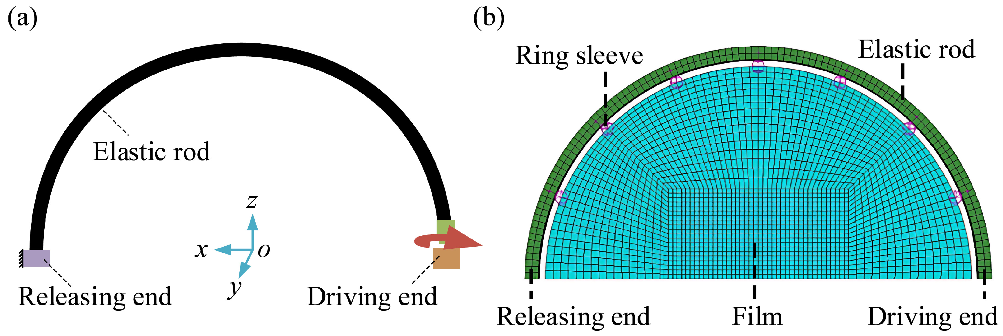
The initial radius of the rod centerline is 70 mm (
Figure 4a). Replacing the bending process from a straight line into a semicircle, a residual stress field is imposed on the rod. The Poisson’s ratio of the material is set as 0.47. The Young’s modulus is determined by the uniaxial tension test, which is set as 3 MPa. The rod is discretized by 3266 C3D8R elements. The geometric nonlinearity is taken into account to analyze the large deformation of the rod. The effect of environmental resistance on the elastic rod is considered by introducing Rayleigh damping. The damping matrix is calculated as
where
and
are the mass matrix and the stiffness matrix of the rod, respectively. The damping parameters are set as
and
.
The snap-through simulation is divided into two steps. First, with the releasing end fixed, the driving end rotates along direction in 0–0.9 s. Second, with the driving end fixed, the stored elastic strain energy of the rod is released by rotating the releasing end along direction in 0.9–1 s. Durations for both steps are derived from experimental measurements.
By connecting the flexible film with the elastic rod through the ring sleeves, a bionic pectoral fin is designed (
Figure 4b). In the numerical model, the fin is modeled as a semicircle with a radius of 65 mm and a thickness of 0.2 mm. The fin is discretized using shell elements and assigned the same Young’s modulus (3 MPa) as the elastic rod. Spring connectors are adopted to characterize the connecting effect between the rod and the film. One end of each spring is attached to the center of the elastic rod, and the other end is attached to the edge of the fin. Seven springs are evenly distributed along the fin rim, of which the spring stiffness is set as 100 N/m.
2.3. Theoretical Prediction
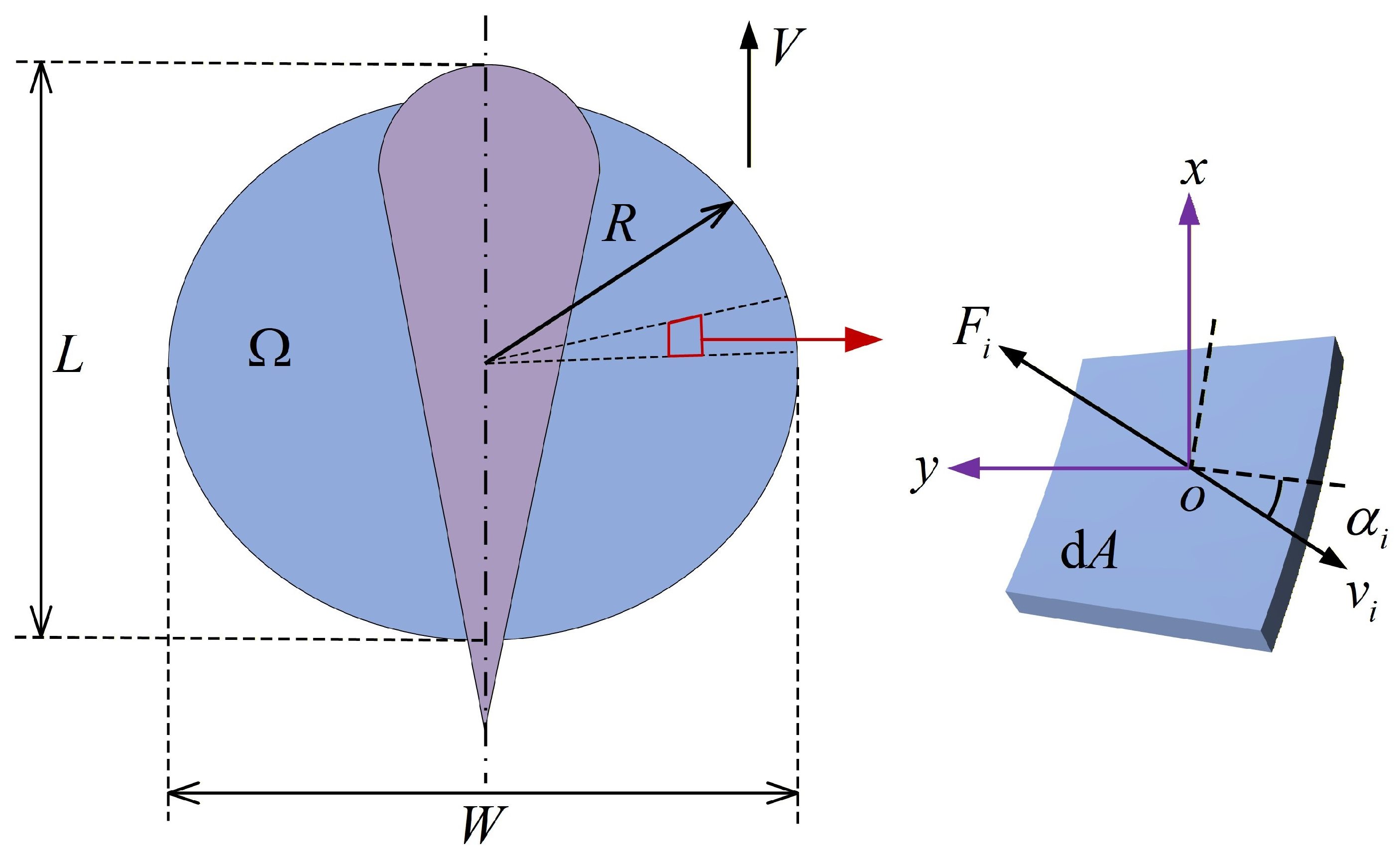
The propulsive force of the robotic fish is determined using a differential element method. In this approach, the oval fin is discretized radially into multiple small elements. As shown in
Figure 5, a right-handed Cartesian coordinate system (
) is introduced, where the origin
positioned at the center of element
, the
axis is along the swimming direction of the fish, and the
axis is along the spanwise direction of the fish.
The velocities of the elements in the fin are obtained from the dynamics analysis introduced in
Section 2.2. The normal and tangential forces that the fluid acts on each element are calculated as [
47,
48].
respectively. The normal force coefficient
, the tangential force coefficient
, and the Reynolds number
.
is the angle between the plane where element
is located and the velocity vector of element
.
is the mass density of the fluid,
the element area,
the velocity of element
,
the radius of the film, and
the kinematic viscosity of the fluid. The total thrust and lift of the fish is expressed as
respectively.
represents the oval fin surface.
and
are the components of the normal and tangential forces along the
axis, respectively.
and
are the components of the normal and tangential forces along the
axis, respectively.
To estimate the drag, the robotic fish is simplified as a cuboid, of which the length
, the width
, and the thickness
. The drag that impedes the propulsion of the fish is calculated as [
49]
where
is the drag coefficient and
is the swimming speed of the fish.
2.4. Experimental Measurement
2.4.1. Uniaxial Tension Test
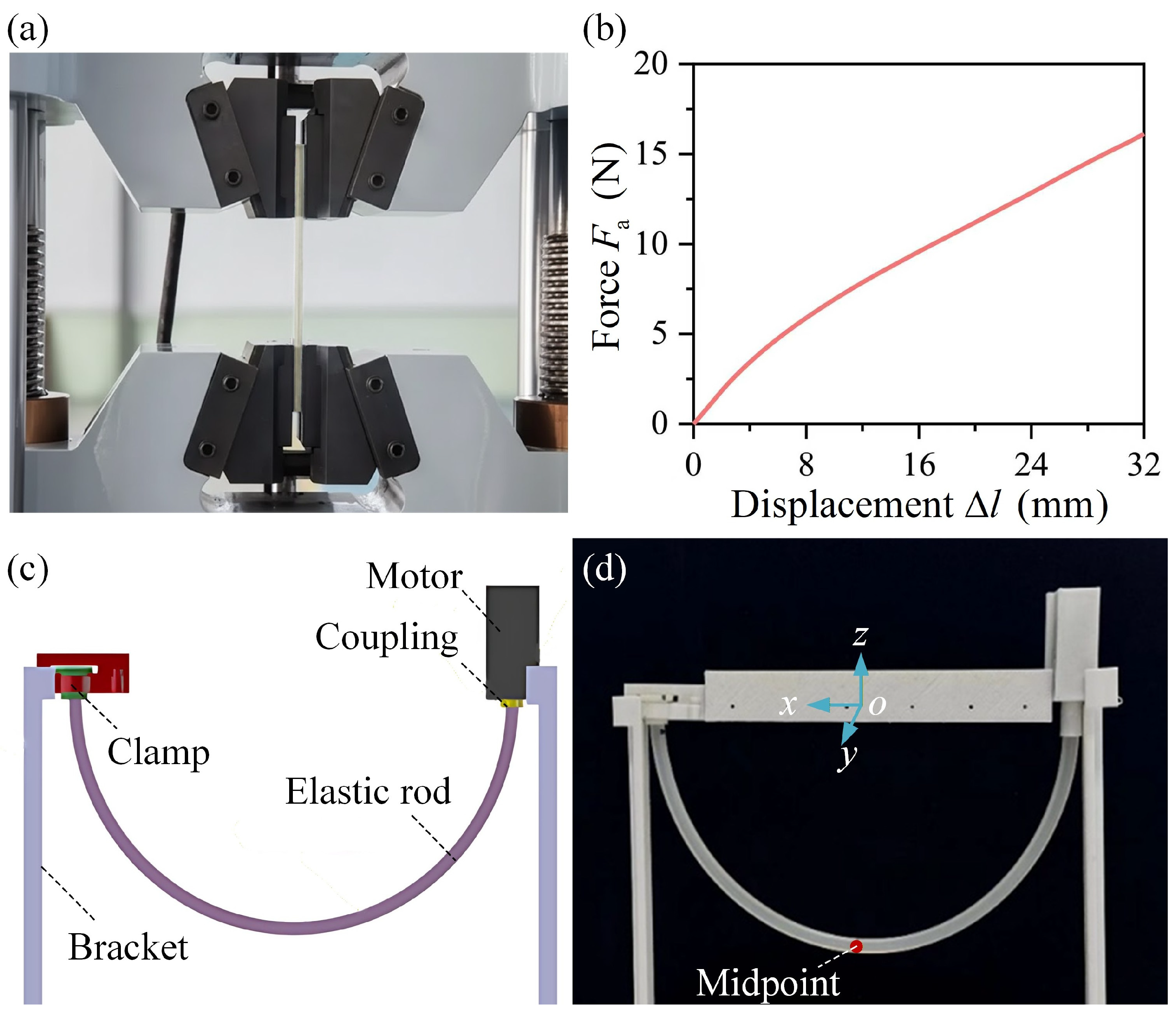
The stiffness of the elastic rod is measured using a universal testing machine (MTS Exceed E43, MTS Industrial Systems Co., Ltd., Shanghai, China). The length of the elastic rod is
. The side length of the square cross-section is
. As shown in
Figure 6a, the two ends of the elastic rod are fixed by the fixture components of the testing machine. The Young’s modulus of the material is calculated as
, where
and
are the axial stress and strain of the rod, respectively.
and
, where
is the axial force and
is the increment in length of the rod.
curve is plotted in
Figure 6b. Based on the experimental results, the Young’s modulus of the rod is set as
.
2.4.2. Torsion Test
The experimental setup for the torsion test of the elastic rod is shown in
Figure 6c, which consists of a bracket, a motor, a coupling, a clamp, and an elastic rod. A camera is used to record the rotational angle of the driving end and the morphological evolution of the rod.
The length of the elastic rod used in the torsion test is set as 22 cm. The rod is first bent into a semicircle with a radius of 7 cm (
Figure 6d). Then the motor at the driving end is activated in 0–0.9 s. The releasing end rotates in 0.9–1 s to release the elastic strain energy of the rod. The midpoint of the elastic rod is marked by a red marker, allowing the measurement of its deviation from its initial position.
2.4.3. Swimming Test
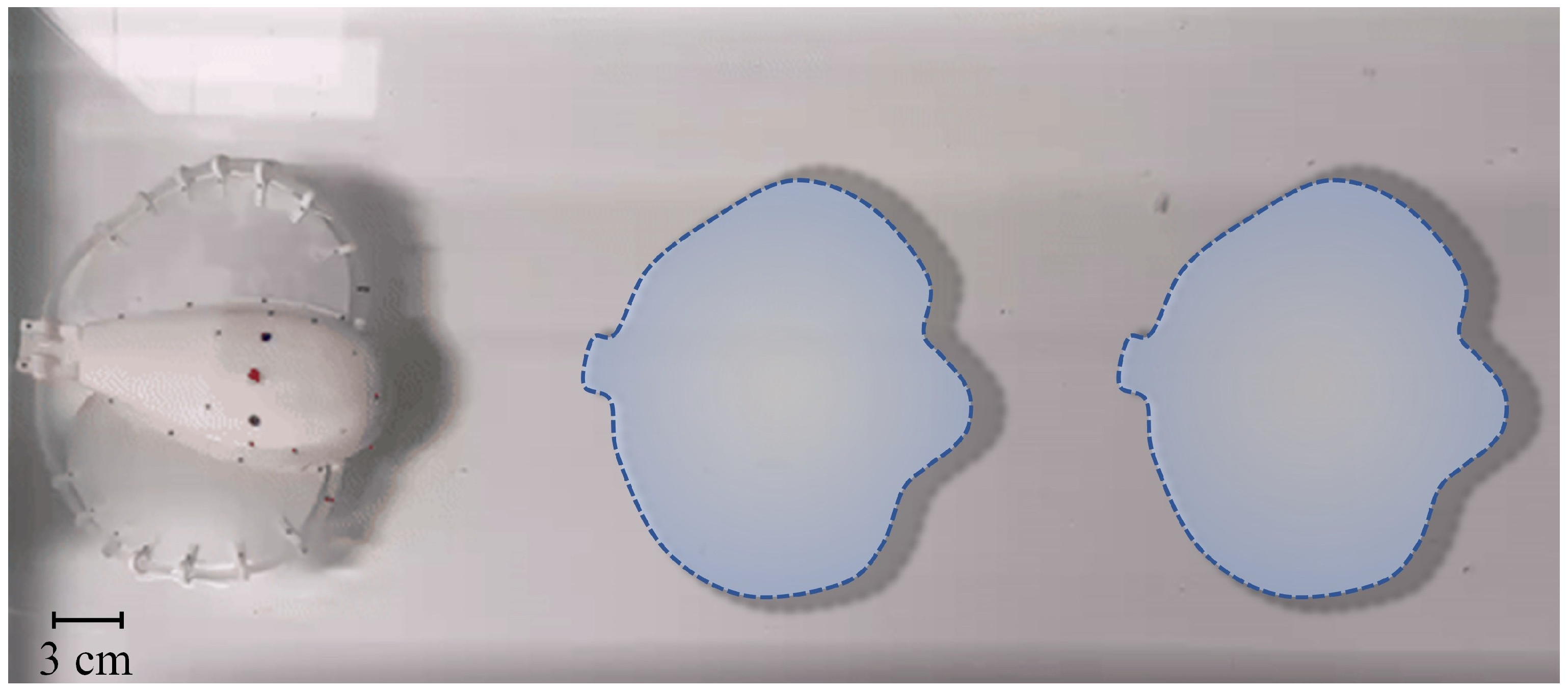
The swimming tests are conducted in a glass tank with the dimensions of
(
Figure 7). The tank is filled with water to a depth of 40 cm. The motion of the robotic fish is recorded by a camera in top view. At the beginning of each test, the robotic fish is positioned at the left of the tank. The two motors are simultaneously activated to drive the pectoral fins to generate undulatory motion. The time cost of the fish swimming from the left to the right end is recorded. The averaged swimming speed of the robotic fish is determined by the ratio of the distance between the two ends and the time taken by the fish passing through the two ends.
3. Results
In this section, we investigate the buckling behavior of the torsional elastic rod and its effect on the swimming performance of the robotic fish. First, the buckled patterns of the elastic rod in various cases are analyzed. Then, it is examined how the initial fin shape, the motor speed, and the friction at the releasing end influence the propulsion performance of the robotic fish. Further, the maneuverability is evaluated through the measurements of the angular speed and turning radius.
3.1. Instability Analysis
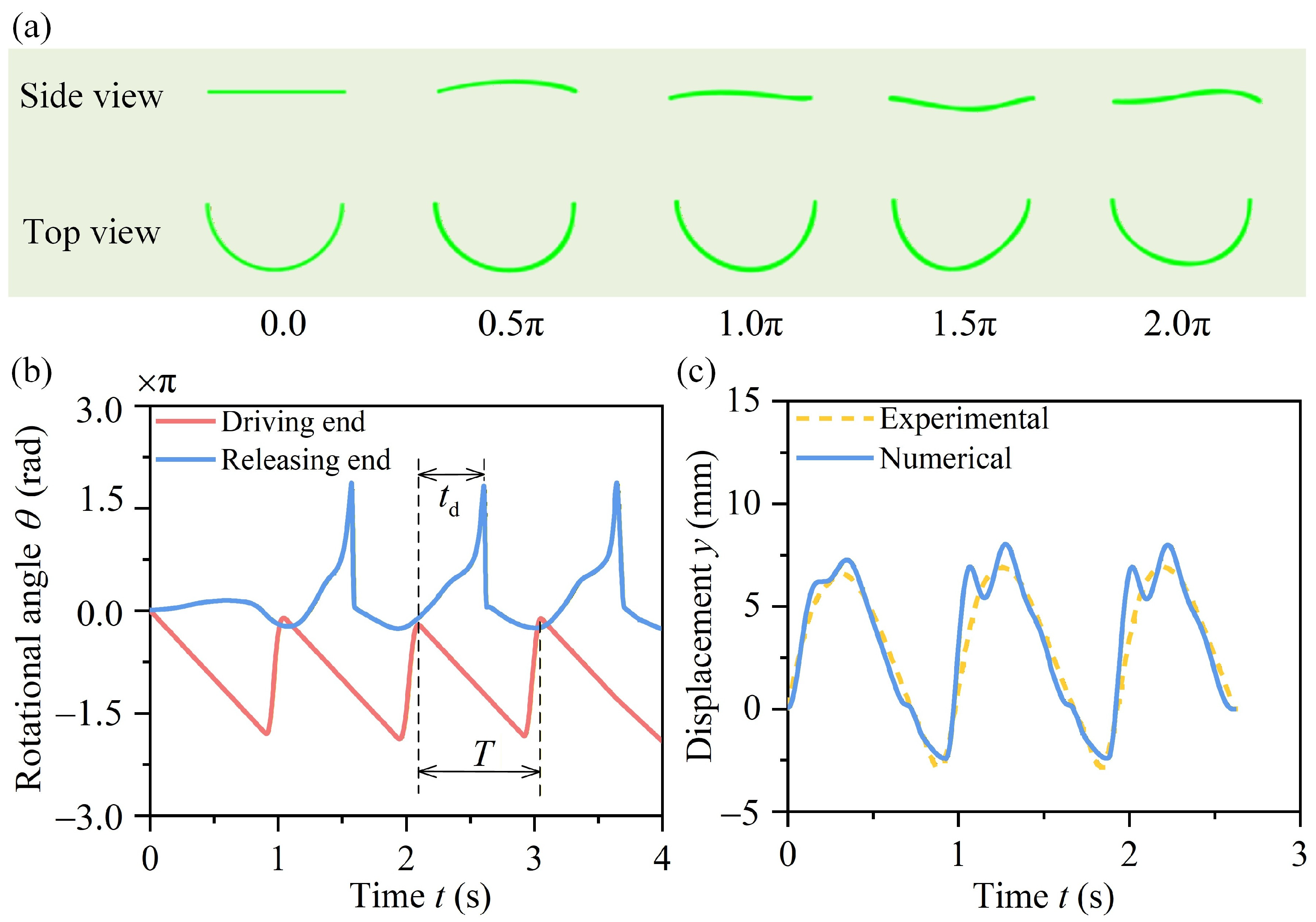
Figure 8a illustrates typical post-buckling configurations of the rod. As the driving end rotates, the rod experiences a spatial deformation, resulting in a wavy shape. The variations of the rotational angles
at the driving and releasing ends with time
are plotted in
Figure 8b. During a deformation period, the rotational angle at the driving end increases stably, while that at the releasing end exhibits an impulse wave. When the rotational angle at the driving end exceeds a critical threshold, the releasing end undergoes an abrupt rotation accompanied by a rapid release of the stored elastic strain energy. The displacement of the midpoint along the
direction is extracted from the numerical results, which is plotted in
Figure 8c. The numerical results are consistent with the experimental ones.
The underlying mechanism of the snap-through instability of elastic curved rods has been revealed through theoretical and experimental efforts in our previous study [
46]. The results indicated that the morphological evolution of the torsional elastic rod can be controlled by selecting different rod materials, tailoring its initial structural geometry, and adjusting the friction at the releasing end. Based on the numerical model shown in
Figure 4a, we have optimized the design of the elastic rod, which is adopted in our bionic fish to improve its swimming performance.
3.2. Propulsion Performance
This section systematically investigates the influence of three key parameters, i.e., the initial fin shape, the motor speed, and the friction at the releasing end, on the swimming performance of the robotic fish. Numerical simulation, theoretical analysis, and experimental measurement are combined to reveal a comprehensive insight into their effects.
A physical prototype was fabricated to validate the swimming performance experimentally (
Figure 9a). The results show that twisting the elastic rod can enable a butterfly stroke, propelling the robotic fish through water (see
Supplementary Movie S1). The morphological evolution of the undulating fins over a swimming cycle is depicted in
Figure 9b. The wave amplitude relative to the body length is comparable to that observed in the swimming motion of
Potamotrygon motoro.
3.2.1. Effect of the Initial Fin Shape
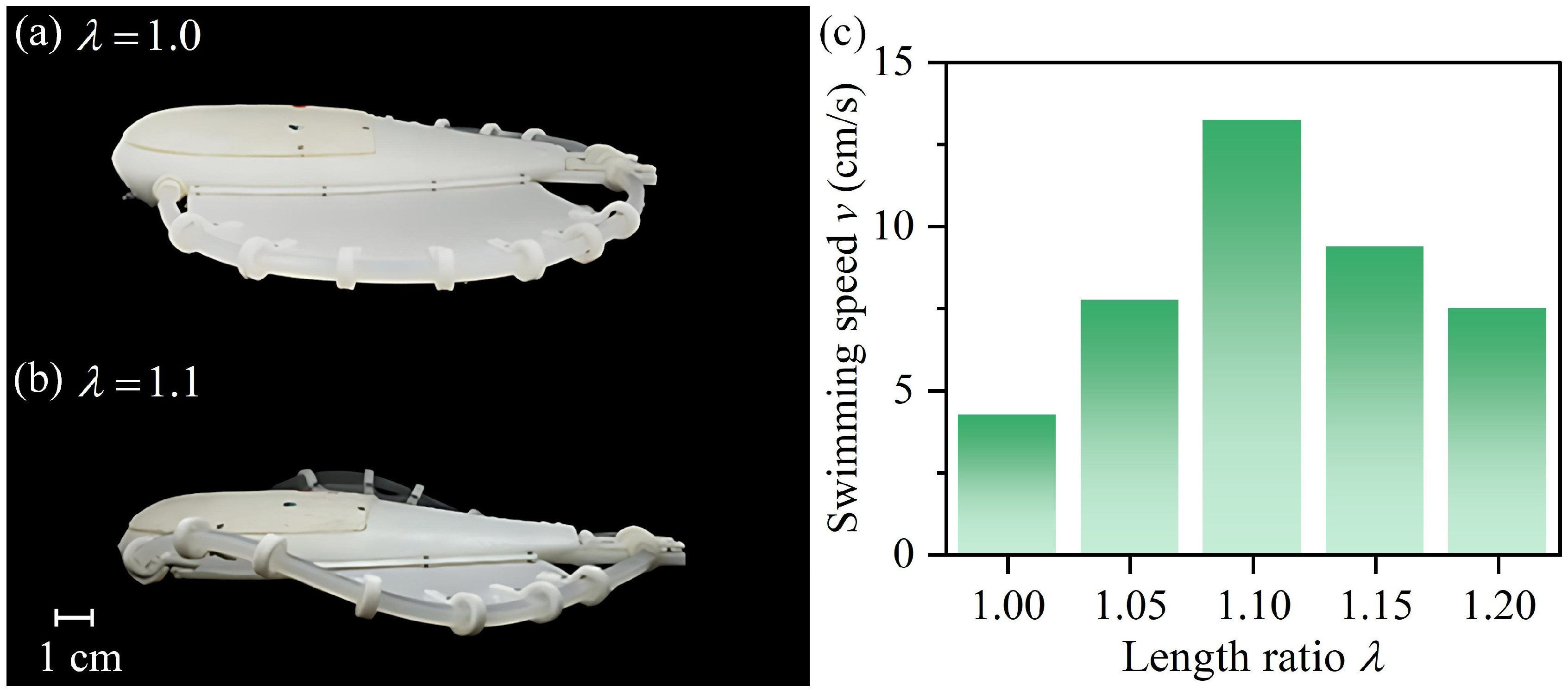
Here, we fabricated five fins with different length ratios of the rod. As shown in
Figure 10a, the elastic rod is initially bent into a semicircular shape. Let
denote the total length of the rod in this case. When the length
of the rod increases, the constraints imposed by the ring sleeves, clamp, and coupling cause the rod to undergo out-of-plane deformation (
Figure 10b). The length ratio is defined as
. The larger the length ratio, the greater the wave amplitude of the fluctuating fin.
The effect of the length ratio ranging from 1.0 to 1.2 on the swimming speed of the robotic fish is shown in
Figure 10c. As the length ratio increases, the swimming speed first increases and then decreases. Let BL represent the body length of the robotic fish. In the case of
, the maximum swimming speed reaches 13 cm/s, i.e., 0.76 BL/s. Compared with that of the fish in the case of
, the swimming speed increases by
when
. These results demonstrate that the initial shape of the fin is crucial for enhancing the swimming performance.
3.2.2. Effect of Motor Speed
The flapping frequency of the pectoral fins is determined by the motor speed, which directly affects the swimming performance of the robotic fish. Using our theoretical model introduced in
Section 2.3, the thrust and lift of the robotic fish are predicted. When the robotic fish swims at a constant speed, the drag acting on the fish is equal to the thrust. Then its swimming speed can be calculated by Equation (6). Theoretical prediction is performed across a motor speed range from
to
. Furthermore, experimental measurements of the swimming speed corresponding to the motor speed range are conducted to verify the theoretical results.
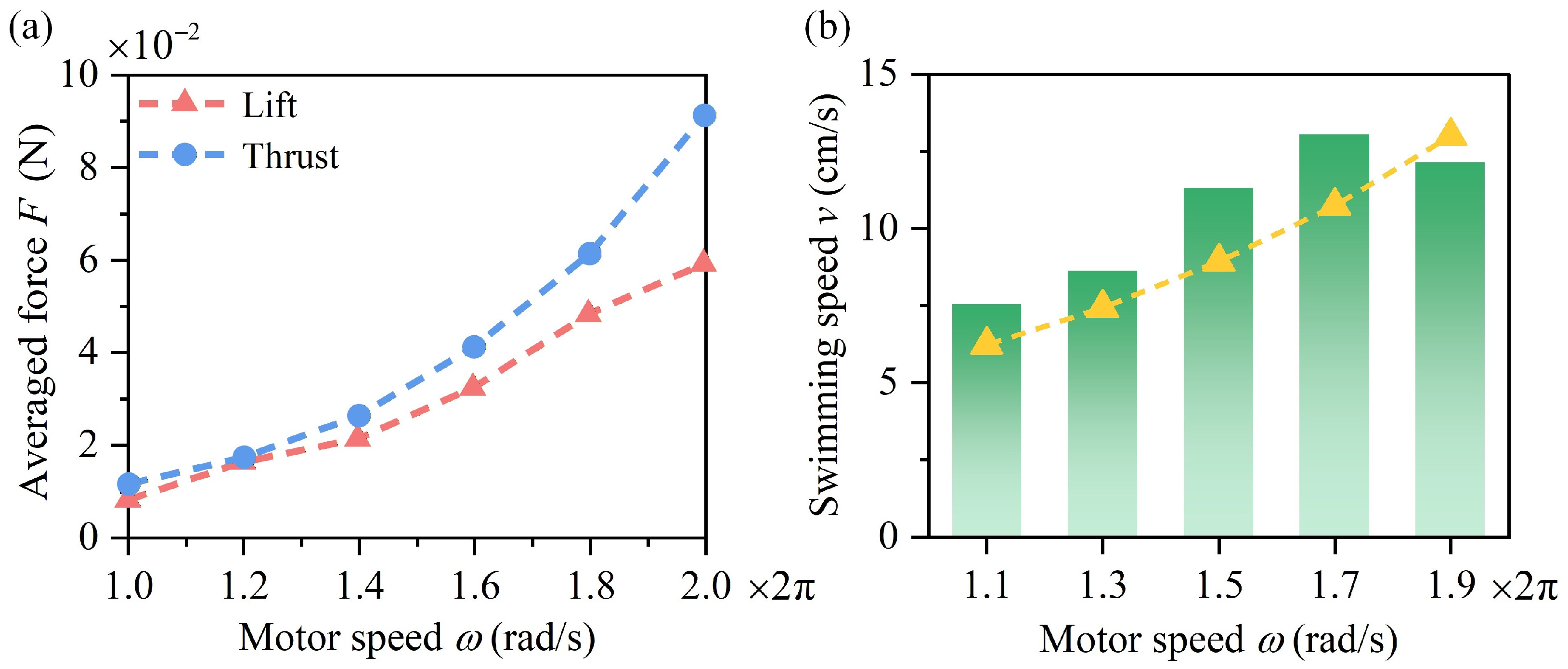
As the motor speed
increases, the thrust and lift both increase (
Figure 11a). The increase in thrust is greater than that in lift.
Figure 11b shows the variation in the swimming speed with
. The theoretical predictions slightly deviate from the experimental results. The interaction between the soft fin and the fluid is neglected in the theoretical model, which may lead to the observed discrepancies. Specifically, the robotic fish is simplified as a cuboid, neglecting its streamlined body shape, which may cause an overestimation of drag. As a result, at low to moderate motor speeds, the theoretical predictions are slightly lower than the experimental measurements. At high motor speeds, the flow becomes increasingly turbulent, which tends to enhance drag and reduce thrust [
50,
51]. Neglecting this turbulent flow behavior may therefore result in an overestimation of the theoretically predicted swimming speed compared with the experimentally measured one. Considering the coupling between the structural snapping dynamics and the fluid dynamics may further improve the accuracy of the theoretical model, which needs further research.
The experimental results show that the swimming speed increases with the motor speed when . However, when , the swimming speed begins to decrease. An excessively high flapping frequency of the pectoral fins can disturb the surrounding water, which may induce turbulence and significantly increase the environmental drag. As a result, at overly high motor speeds, the robotic fish tends to swim more slowly.
3.2.3. Effect of Friction
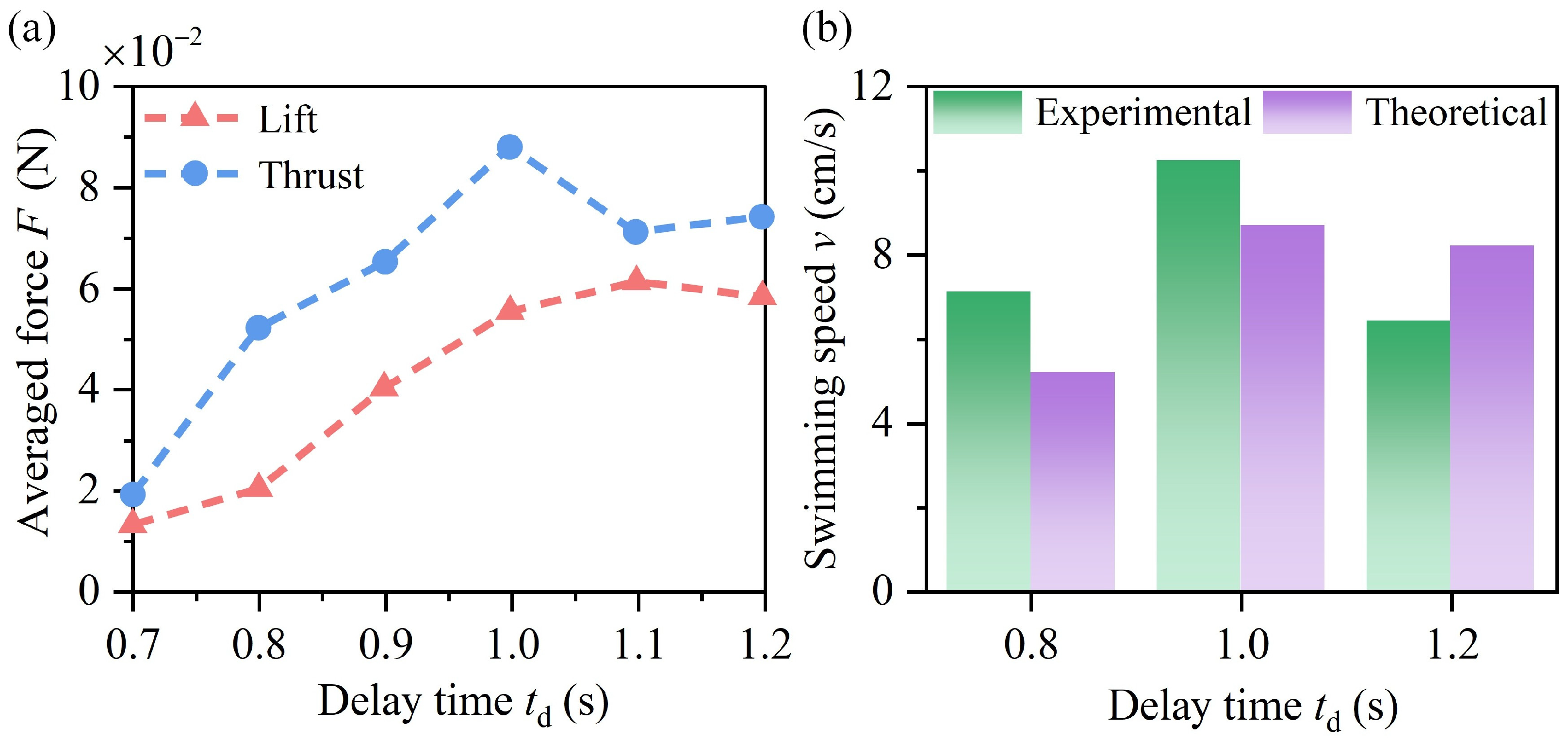
Delay time is adopted to quantify the magnitude of friction at the releasing end, which is defined in
Figure 8b. During a deformation period, the delay time
is defined as the interval between the onset of rotation at the driving end and the moment when the rotational angle at the releasing end reaches its maximum. The longer the delay time, the greater the friction at the releasing end. As
increases, both the thrust and lift of the robotic fish first increase and then decrease (
Figure 12a). The variation of the swimming speed with
is shown in
Figure 12b. The swimming speed follows the same trend as the thrust, increasing first and then decreasing. Therefore, to achieve a higher swimming speed, a moderate level of friction at the releasing end is required. The theoretical predictions show slight deviation from the experimental results (
Figure 12b). In the cases of long delay times, the fin oscillations exhibit higher frequency and larger amplitude, leading to more pronounced turbulence. The mechanism underlying the discrepancies at different delay times is similar to that at different motor speeds. At short delay times, the theoretical model overestimates drag, whereas at long delay times, it overestimates thrust and underestimates drag.
To evaluate the propulsive efficiency of the robotic fish, an important dimensionless quantity is the Strouhal number
[
45,
52], which is defined as
.
is the flapping frequency of the fin,
the wave amplitude of the fin, and
is the forward swimming speed of the fish. The optimal range for high propulsive efficiency is
, which is adopted in biological swimmers [
53]. A comparison of the Strouhal number among the existing soft robotics is shown in
Table 1. The Strouhal number of our design falls within the observed naturally selected narrow range of
. It indicates that our robotic fish can achieve both a high swimming speed (
) and a high propulsive efficiency (
).
Assume that the current input of the motor is a triangular wave with the maximum
[
46]. Then, the averaged power input of one motor can be calculated as
, where
is the rated voltage of the motor. The cost of transport (CoT) is an indicator that reflects the energy consumption of the robot. The smaller the CoT, the lower the energy consumption. The CoT is defined as
[
45], where
is the robotic mass and
the standard acceleration of gravity. The total mass of our robotic fish is
. Its CoT is measured as
. Compared with existing underwater soft robots (
Table 1), our robotic fish is featured by low energy consumption.
3.3. Maneuverability
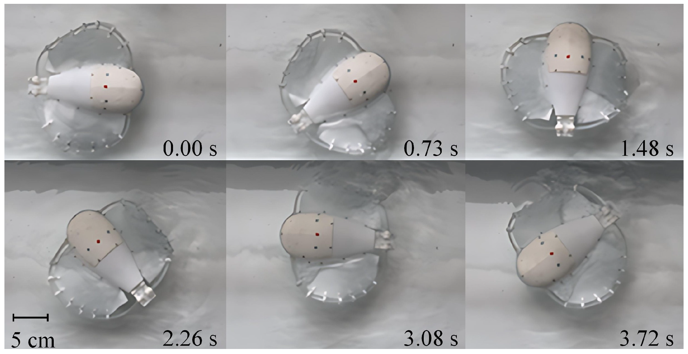
Experiments were conducted to evaluate both the turning angular speed and the turning radius. The robotic fish was placed at the center of the tank, and a single motor was activated to drive the corresponding fin into undulatory motion (
Supplementary Movie S2). The time required to complete a
rotation was recorded, and the averaged turning speed was calculated as the ratio of angular displacement to the measured time. The entire motion process was recorded by a camera in top view (
Figure 13). The turning radius was determined by extracting the trajectory of a red marker on the robot.
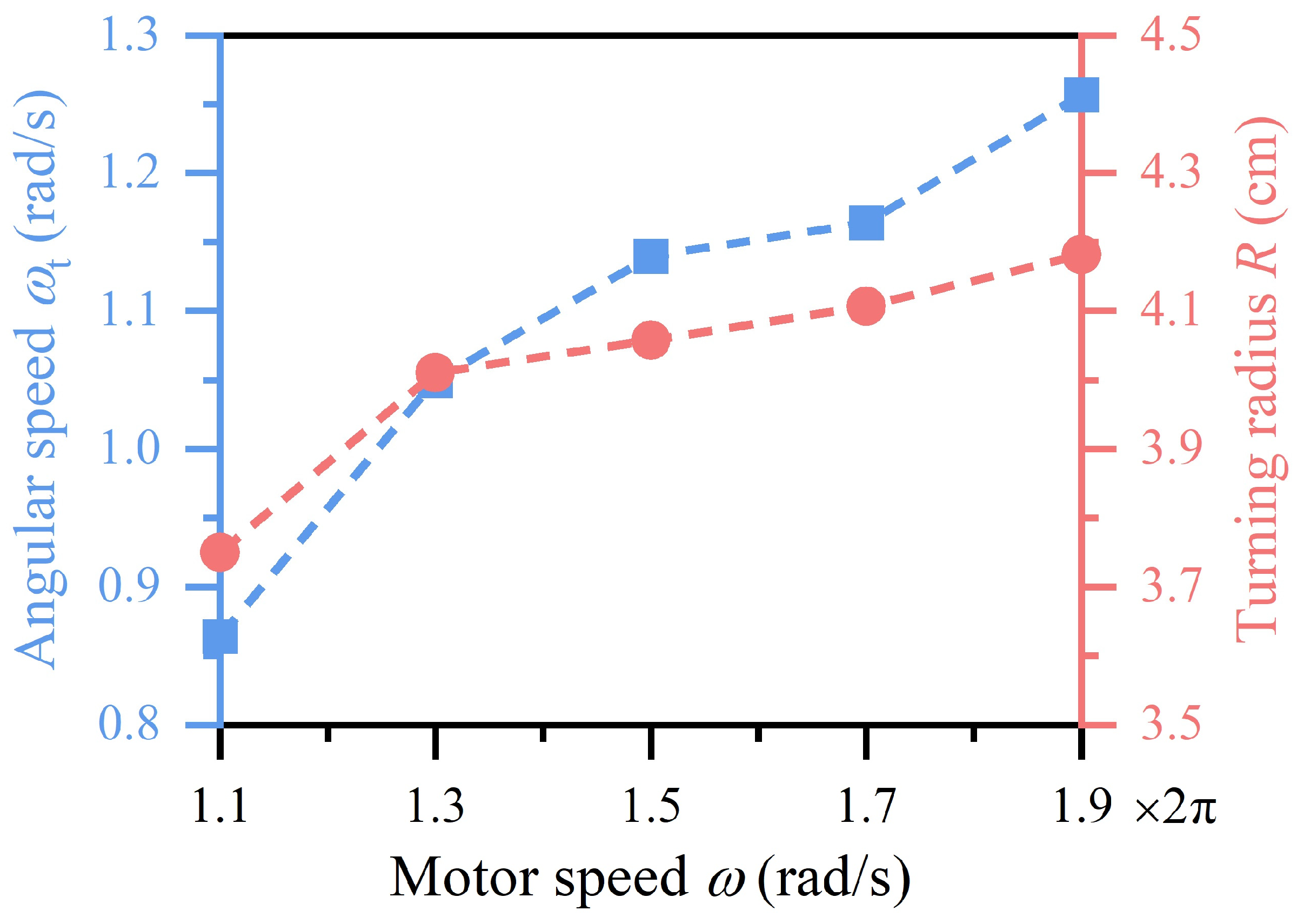
Figure 14 presents the variations of the turning angular speed
and the turning radius
with the motor speed
. As the motor speed increases, the turning angular speed increases. When the motor speed is larger than
, the turning radius varies slightly, remaining appropriately 4 cm. The increase in the turning angular speed enhances the maneuverability and adaptability of the robot in complex aquatic environments. The small turning radius contributes to precise navigation during turning maneuvers.
4. Discussions
In this study, numerical, theoretical, and experimental efforts are combined to evaluate the swimming performance of the robotic fish under various operating conditions. The length ratio of the elastic rod has a significant effect on the swimming speed. Appropriately increasing the rod length could enlarge the amplitude of the undulatory fin motion and thereby enhance the swimming performance of the robotic fish. As the motor speed increases, the flapping frequency of the fins increases accordingly. However, an excessively high frequency may lead to unstable fluid flow, which may reduce the thrust generated through fin–water interaction and thereby decrease the swimming speed of the robotic fish. The effect of friction at the releasing end is non-monotonic, exhibiting an optimal range that balances energy transfer and stability, which is consistent with the previous study [
46]. These results demonstrate that the initial fin shape, the motor speed, and the friction at the releasing end collectively affect the swimming performance of the robotic fish. A combination of an appropriate initial fin shape, moderate motor speed, and balanced friction enables the robotic fish to achieve efficient, stable propulsion.
In contrast to conventional ray-inspired designs that rely on multiple components and complex control systems to replicate manta-like strokes [
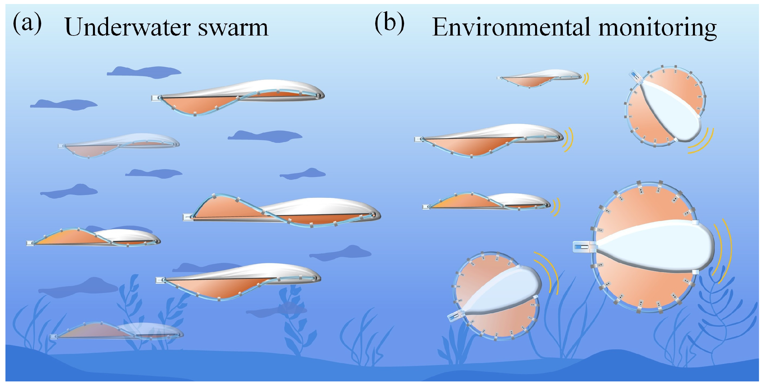
30], our approach achieves comparable biomimetic motion through a simple and efficient structure. By harnessing the elastic instability of a torsional rod, the robotic fish achieves coordinated MPF propulsion using only two actuators. This mechanically intelligent design eliminates the need for complex control algorithms, reduces the energy consumption, and improves the reliability and endurance. The low manufacturing cost also facilitates its scalable fabrication and deployment in practical applications, e.g., underwater swarm (
Figure 15a).
Compared with propeller-based propulsion systems [
55], the proposed mechanism provides distinct advantages, including lowered noise, reduced environmental disturbance, and enhanced safety for marine life, making it applicable for such long-term underwater operations as environmental monitoring (
Figure 15b). By independently controlling the left and right motors through a wireless system, the robot exhibits excellent turning performance. Our robotic fish could achieve an agile turning with a maximum angular speed of 1.25 rad/s. Small-radius turning and stable navigation enable the robot with superb adaptability to complex aquatic environments.
The snap-through dynamics plays a crucial role in enhancing the swimming performance of the proposed robotic fish. Unlike pneumatic or electromagnetic actuation methods, which rely on continuous energy input to sustain deformation [
56,
57], the elastic snap-through of the pre-curved rod stores and releases the mechanical energy in a highly efficient approach. This cyclic energy exchange between elastic strain energy and kinetic energy minimizes the energy dissipation, allowing rapid, large-amplitude fin motion with relatively low actuation power. Compared with pneumatic actuation [
45,
58], which typically requires bulky external compressors and exhibits long response times, the snap-through–driven mechanism achieves faster actuation with compact hardware and improved controllability. In contrast to electromagnetic actuation [
59,
60], which experiences heating and energy loss due to magnetic hysteresis, our design only relies on the mechanical energy conversion, thereby offering better long-term stability and endurance. Electromagnetic actuation involves relatively high cost [
57], whereas that of the proposed robotic fish is low, rendering it more suitable for large-scale underwater swarm applications.
It is seen from
Table 1 that our robotic fish is featured by high swimming speed, superb propulsive efficiency, and low energy consumption. A soft underwater robot, of which the maximum speed reaches 3.74 BL/s, swims much faster than many of the other designs [
45]. However, its CoT is distinctly higher than our robotic fish. Furthermore, its pneumatic actuation mechanism demands a larger workspace than the motor-driven mechanism of our robot. Compared with a manta ray-inspired robot with a variable stiffness fin [
54], our robotic fish exhibits both a higher swimming speed and lower energy consumption. Compared with the existing robotic ray [
46], while the energy consumption of our design is slightly larger than their robot, the maximum swimming speed of our design increases by 250%.
Overall, the presented robotic fish combines high efficiency, low energy consumption, excellent maneuverability, and superior environmental compatibility in a simple mechanical system. The environmentally friendly undulatory propulsion allows seamless integration into natural aquatic environments without harming marine life. Extending this concept to other swimming or crawling soft robots could further advance the development of mechanically intelligent systems.
5. Conclusions
In summary, we have developed a bionic robotic fish by exploiting the snap-through instability of elastic curved rods. The proposed design realizes the continuous and smooth transformation of rotary motion from two motors into controllable wave-like fin deformation. By changing the initial fin shape, motor speed, and friction at the releasing end, the fish achieves a maximum swimming speed of 0.76 BL/s and executes small-radius turns with a maximum angular speed of 1.25 rad/s. Compared with the multi-actuator systems, our design significantly simplifies structural construction, reduces energy consumption, and enables high maneuverability. The robotic fish exhibits smooth and quiet movement, making it suitable for stealthy underwater operations. This work provides new insights into the development of simple, efficient, and robust underwater robotic systems for, e.g., environmental monitoring and aquatic exploration.
We acknowledge the limitations of this study that warrant improvement. The functions of the robotic fish can be extended by mounting control apparatuses and sensing devices such as chips, cameras, and locators. In addition, based on fluid dynamics analysis, the appearance of the robotic fish could be optimized to achieve a higher swimming efficiency, which needs further research.
