1. Introduction
Flywheel energy storage systems, as an efficient and reliable kinetic energy storage technology [
1,
2], impose stringent requirements on drive machines, including high power density, wide speed range, fast torque response, and low-loss operation. The PMSM, with its high power density, high reliability, and excellent dynamic performance [
3,
4], has become an ideal choice for flywheel energy storage applications. Its control performance directly affects the energy conversion efficiency and operational stability of the entire system. As the demands for higher power and speed in aerospace, electric vehicles, and industrial equipment, drive systems face greater challenges. Conventional vector control based on PI regulators suffers from difficulties in parameter tuning and balancing dynamic and steady-state performance under high-speed and high-power conditions. In contrast, DPCC, which utilizes a machine model for feedforward prediction, offers advantages such as fast dynamic response and elimination of parameter tuning, making it more suitable for high-performance applications like flywheel energy storage.
In low-speed high-power and high-speed applications, the carrier ratio—defined as the ratio of the inverter switching frequency to the fundamental frequency of the machine—is often limited due to switching losses, thermal constraints, and system efficiency. A carrier ratio below 15 is typically considered low. Under such conditions, the model error of conventional DPCC increases significantly [
5,
6]. On the one hand, discretization errors and control delays have a more pronounced impact on control accuracy and system stability; on the other hand, the larger electrical angle increment within a single control cycle exacerbates the coupling between torque and flux. Excessively low carrier ratios may even lead to current loop instability [
7,
8].
To address these issues, existing research on low-carrier-ratio machine control has focused mainly on delay compensation, discrete errors, and rotor movement effects [
9]. First, discrete control introduces a zero-order hold effect with a delay of 1
Ts, which reduces control bandwidth and can destabilize dynamic processes. A common compensation method is to add phase lead [
10,
11]; some studies also account for the 0.5
Ts pulse width modulation (PWM) delay [
12], though such approaches often overlook the timeliness of the voltage reference. Second, the discrete nature of the controller also leads to current sampling errors. The
dq-axis currents calculated from sampled values at the current instant may not accurately represent the actual values over the entire control period. In [
13], an open-loop model-based error estimator to compensate for discrete current sampling errors was proposed. Furthermore, discretizing the continuously rotating rotor reference frame inevitably introduces rotor movement effects, causing deviations between the output voltage and reference voltage—especially non-negligible at low carrier ratios. To counteract voltage reference errors due to rotor movement, the average reference voltage based on volt-second equivalence is applied [
12], combined with delay compensation, to match output and reference voltages. Synchronous transformation is avoided via deadbeat control using flux linkage in the stationary frame, albeit at the cost of higher computational burden [
13]. For torque and flux coupling, complex vector decoupling models with zero-pole cancelation are adopted [
14,
15,
16,
17] to reduce dq-axis coupling. This method, however, suffers from limited bandwidth and inadequate dynamic performance. Meanwhile, in [
18] it is demonstrated that the controller zeros designed for a continuous system cannot accurately cancel the poles of the discrete motor model, with the cancelation precision degrading as the carrier ratio decreases. In [
19], an online least squares support vector machine is utilized to construct an inverse system for the PMSM, achieving system linearization and decoupled control; however, this method depends critically on the accuracy and response speed of the flux observer. Furthermore, overcurrent risks and multi-source disturbances also pose critical challenges to high-performance PMSM control. To address these issues, studies have employed methods such as current-constrained sliding mode control to enhance system robustness [
20,
21]. However, these approaches primarily focus on anti-disturbance design for single-loop speed control systems and do not resolve the inherent model inaccuracies and multi-coordinate computational discrepancies in deadbeat predictive current control under low carrier ratio conditions.
The above analysis indicates that as the carrier ratio decreases, control methods based on conventional rotor reference frame models exhibit increasingly prominent limitations. Most existing studies focus on compensation strategies rather than addressing inherent model inaccuracies. In fact, under low carrier ratios, the conventional stator voltage equation in the synchronous rotating frame is no longer applicable, leading to inherent model errors in conventional DPCC. Moreover, the participation of variables from multiple coordinate systems in the prediction process introduces additional computational errors. Therefore, this paper establishes a modified stator voltage equation that accounts for rotor flux orientation error, thereby mitigating dq-axis coupling under low carrier ratios. Furthermore, a multi-coordinate variable synchronization method is proposed to eliminate prediction and voltage reference errors caused by cross-frame calculations, achieving accurate deadbeat predictive current control suitable for both high and low carrier ratio operation of PMSMs.
2. Conventional Non-Sampled Predictive Current Control
2.1. Control Principle
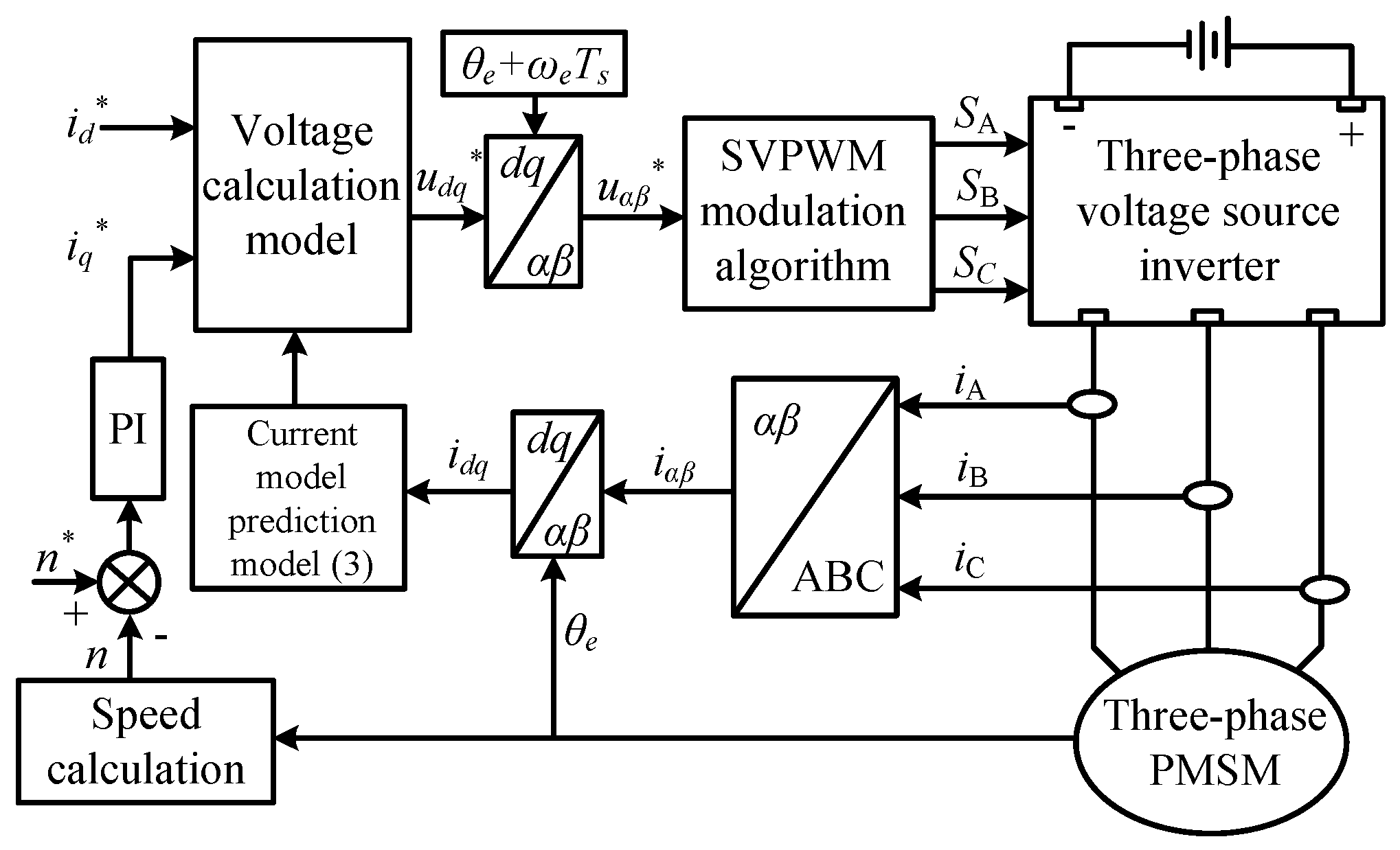
The implementation of conventional DPCC primarily involves current prediction and reference voltage calculation [
22,
23,
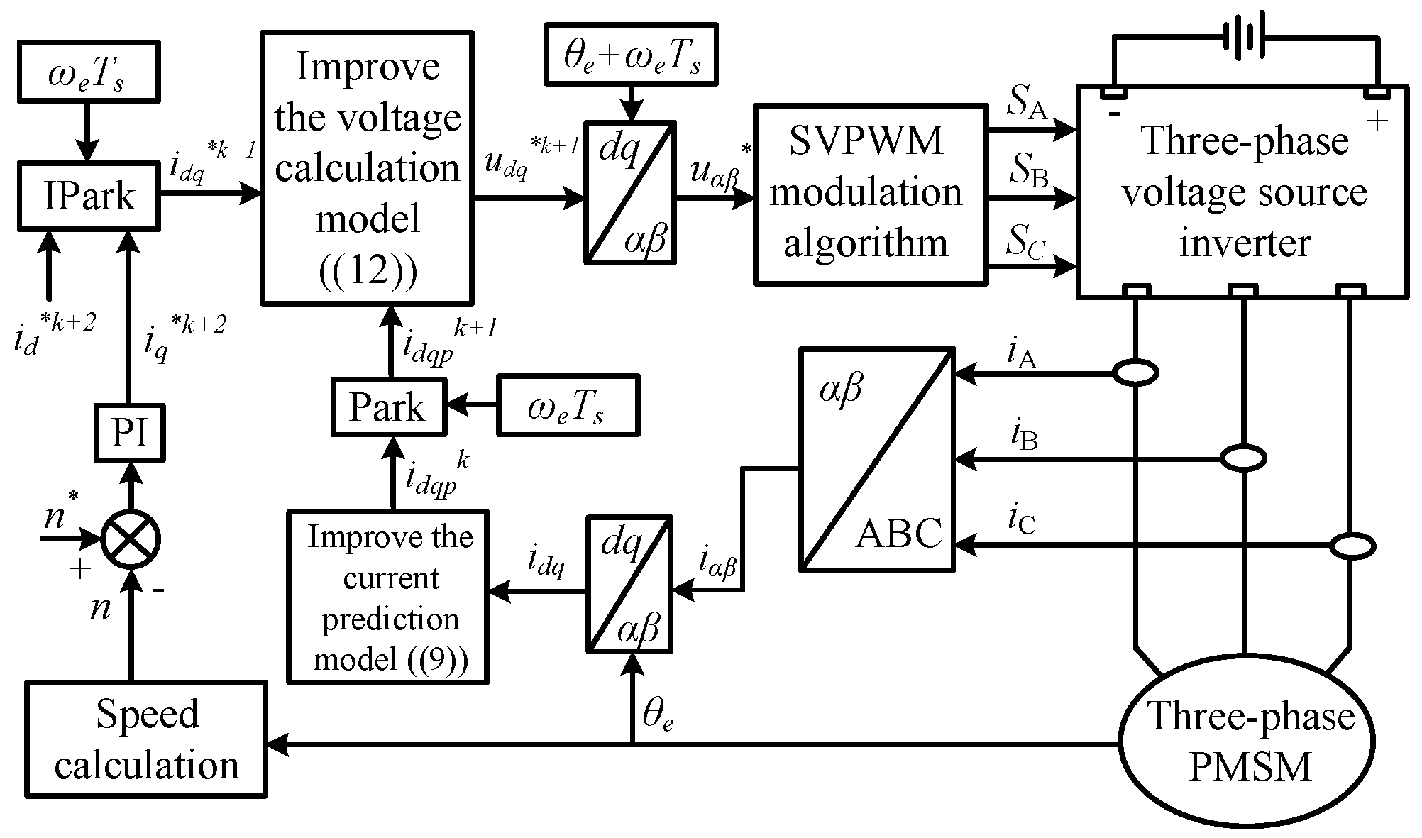
24]. First, the sampled values of the stator currents are substituted into the discrete machine voltage equation to predict the current for the next control cycle. A one-step delay compensation is applied to counteract the inherent one-control-step delay of the digital controller. Subsequently, the reference current values and the predicted current values are substituted into the discrete machine voltage equation to calculate the reference voltage for the next control cycle. The control objective is to force the actual current at the end of the control cycle to equal its reference value, thereby realizing deadbeat predictive current control. A system block diagram of the conventional DPCC strategy is shown in
Figure 1.
In the rotor synchronous rotating reference coordinate, the stator voltage equations of a PMSM are shown as follow:
where
ud,
uq, and
id,
iq are the
d-axis and
q-axis components of the stator voltage and current, respectively;
Rs is the stator phase resistance;
Ld and
Lq are the
d-axis and
q-axis inductances, respectively;
ψf is the PM flux linkage; and
ωe is the electrical angular velocity.
By discretizing Equation (1) using the forward Euler method, the discrete equation for the stator voltage of the machine can be obtained:
where
,
,
,
are, respectively, the command voltage
d and
q-axis components and the predicted current value
d and
q-axis components at (
k + 1)
Ts moment;
and
are, respectively, the
d and
q-axis current components of the given current at (
k + 2)
Ts.
Ts represents the control period.
Rewriting Equation (2) provides the discrete model with one-step delay compensation for the current, the calculation formula for the predicted current, as shown in Equation (3).
where
and
are, respectively, the
d-axis and
q-axis components of the stator current sampling value at the
kTs moment.
To eliminate the controller output delay, compensation for the delayed output angle of the reference voltage is also required. This is because the calculated
d-axis and
q-axis voltages at the current instant will be output at the next instant. Therefore, when transforming the
d-axis and
q-axis reference voltages to the
α-
β plane via the Park transformation, the predicted rotor position angle for the
k + 1 instant should be used. Since the mechanical time constant is much larger than the electrical time constant, the electrical angular velocity
ωe can be assumed constant over one control period. The estimated rotor position for the next cycle can be expressed as
θe +
ωeTs. Thus, the calculation of the reference voltage in the
α-
β plane is:
Deadbeat predictive current control can be accomplished based on Equations (2)–(4). It is important to note that the accuracy of the conventional deadbeat control model relies on the assumption that the d-axis remains perfectly aligned with the rotor flux linkage. However, this premise does not hold in discrete control systems, particularly under low carrier ratio conditions. Violation of this assumption leads to significant model errors.
2.2. Analysis of Control Errors
The primary sources of error in conventional deadbeat predictive current control are machine model inaccuracies caused by discrete control and rotor rotation effects, and calculations involving variables from multiple coordinate systems across different mathematical spaces.
When establishing the stator voltage equation using the conventional method, it is assumed that the d-axis is always aligned with the rotor flux linkage, meaning the dq-coordinate system rotates continuously with the rotor. In reality, within a discrete control system, the position of the d-axis remains fixed at the sampled rotor position value throughout a single control period, effectively making it stationary. Meanwhile, the rotor continues to rotate continuously. Although their directions coincide at the beginning of the cycle, the rotor flux linkage begins to lead the d-axis over time, and this lead angle gradually increases, resulting in a growing rotor field orientation error. Consequently, the conventional assumption of perfect alignment is invalid in discrete control. Therefore, the machine model derived from the conventional method, while accurate and error-free in the continuous domain, exhibits inherent model errors in discrete control. As the carrier ratio decreases, the rotor orientation error increases, exacerbating this model error. This intensifies the coupling between the stator current’s excitation and torque components, leading to control inaccuracies and potentially even system instability under severe conditions.
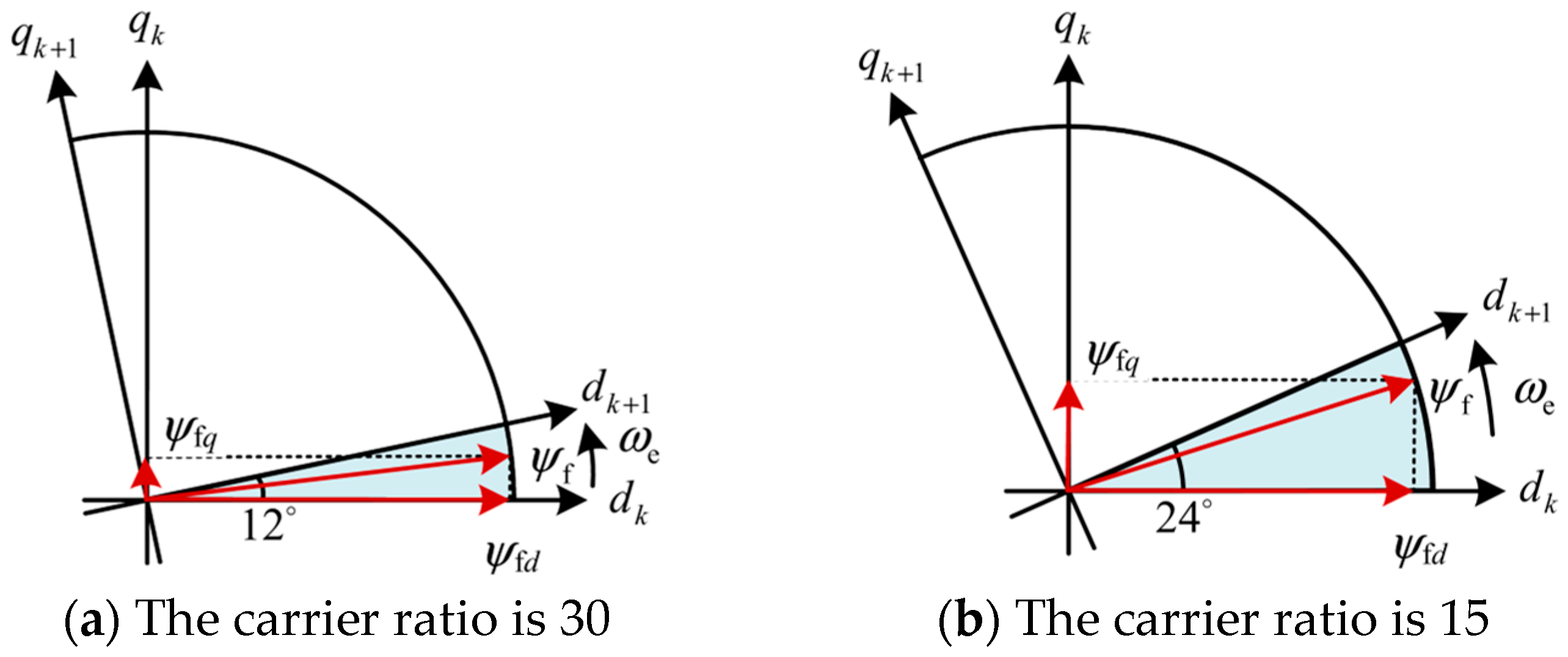
The rotor orientation error within a single control period caused by the rotor rotation effect under carrier ratios of 30 and 15 are shown in
Figure 2, respectively. As shown in
Figure 2, when the carrier ratio is 30, the phase difference between the
d-axis and the rotor flux linkage at the end of the control period is 360°/30 = 12°, resulting in a small component of the PM flux linkage on the
q-axis. When the carrier ratio is 15, the phase difference increases to 360°/15 = 24°, this leads to a significantly larger component of the PM flux linkage on the
q-axis. This indicates that at lower carrier ratios, the rotor rotation effect aggravates the coupling between the machine’s excitation and torque components. Employing conventional deadbeat predictive current control under these conditions will inevitably lead to substantial prediction and control errors, adversely affecting the dynamic and static performance of the machine, and potentially causing system instability.
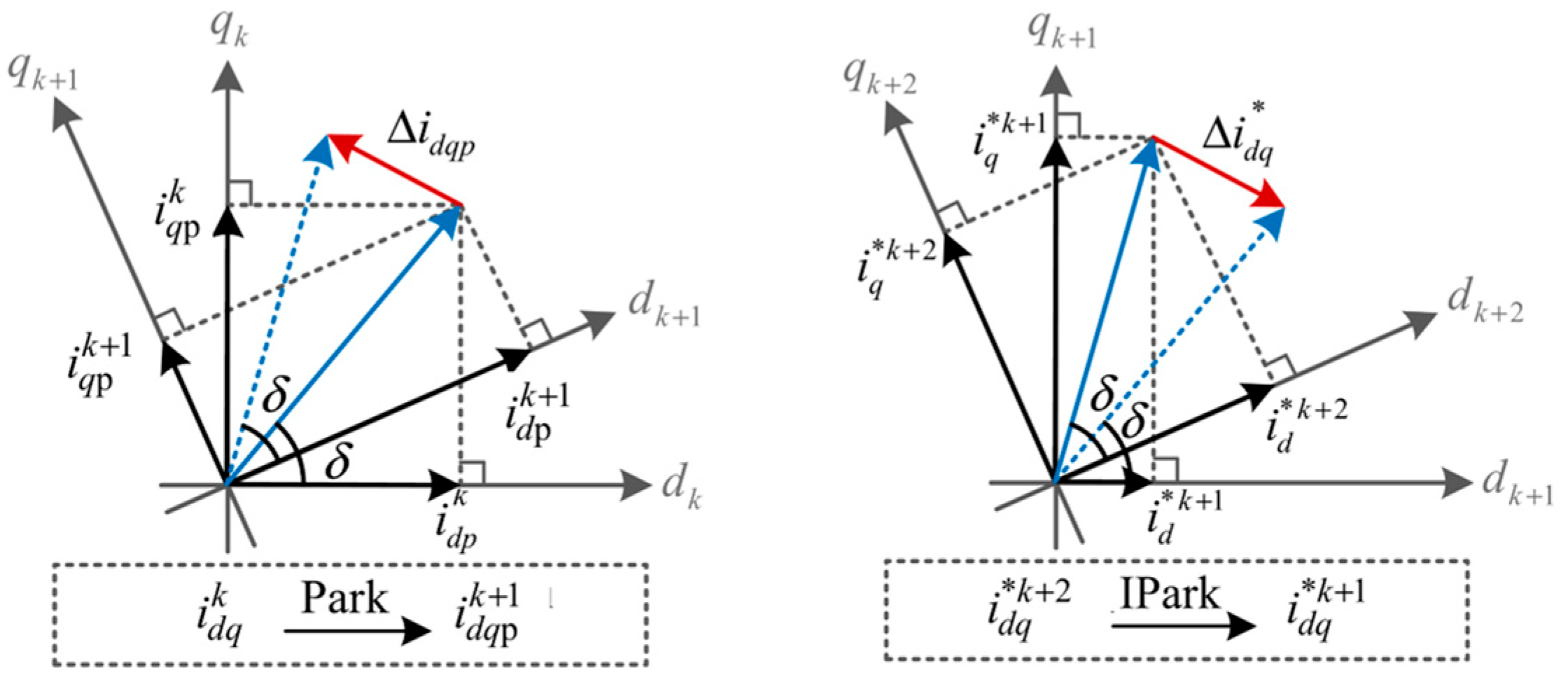
Furthermore, due to the rotor rotation, the spatial position of the synchronous rotating coordinate system differs at each instant, meaning each moment corresponds to a distinct mathematical space. In the prediction process, the reference coordinate system for the sampled current values is the dq-coordinate at time k, the reference coordinate for the predicted current is the dq-coordinate at time k + 1, and the reference coordinate for the current commands is the dq-coordinate at time k + 2. Directly using variables from these three different coordinate systems in calculations across mathematical spaces inevitably introduces errors in both current prediction and reference voltage calculation.
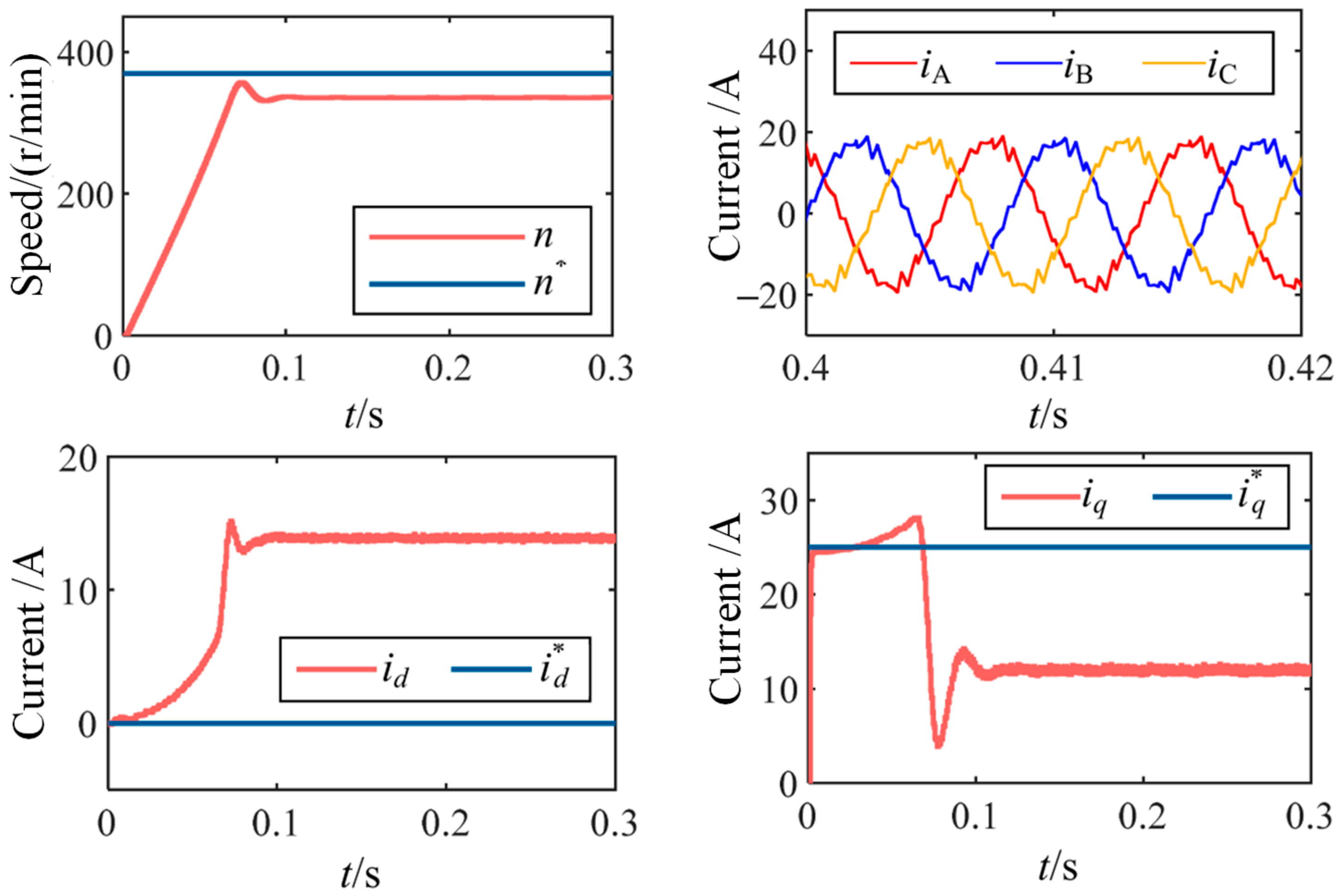
The simulation results using conventional deadbeat control under a carrier ratio of 15 (370 r/min, control frequency 2 kHz) are shown in
Figure 3. The simulation parameters are listed in
Table 1. The results demonstrate that as the speed increases and the carrier ratio decreases, the
d-axis and
q-axis currents gradually deviate from their reference values, and the speed cannot track its reference, exhibiting a steady-state error.
4. Simulated Analysis
A simulation model for PMSM drives was established using the MATLAB/Simulink R2020a platform. The parameters of the target PMSM and the controller are listed in
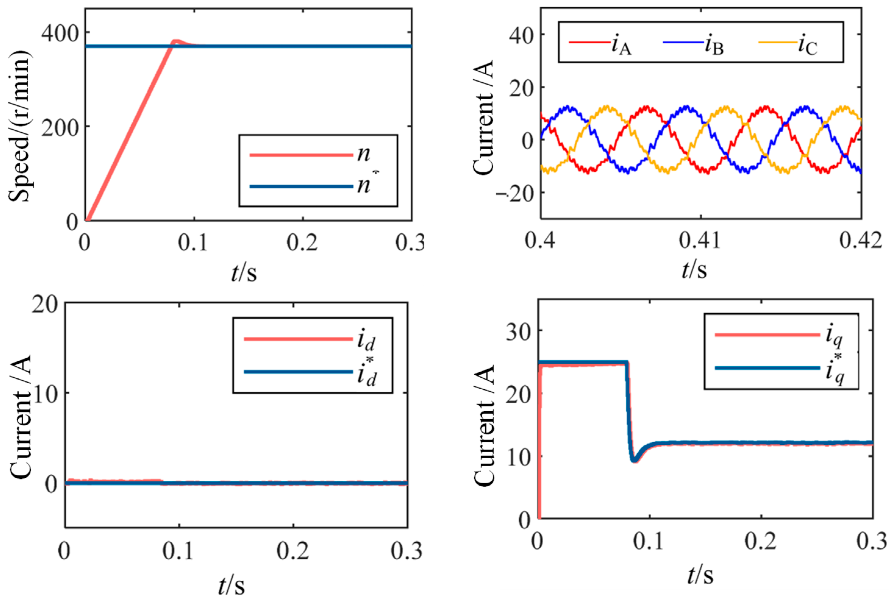
Table 1. The simulation results under improved deadbeat control with a carrier ratio of 15 (370 r/min, control frequency of 2 kHz) are shown in
Figure 6.
Compared with
Figure 3, it can be observed that the improved method achieves better tracking of the
d and
q axis current references and exhibits superior dynamic and steady-state performance in the current loop. Meanwhile, the speed remains stable at 370 r/min without steady-state error. This indicates that the deadbeat control strategy based on the improved voltage model and coordinate system synchronization eliminates the model errors caused by discrete control delay and rotor rotation effects under low carrier ratio conditions, thereby achieving accurate decoupling between
d and
q axis variables.
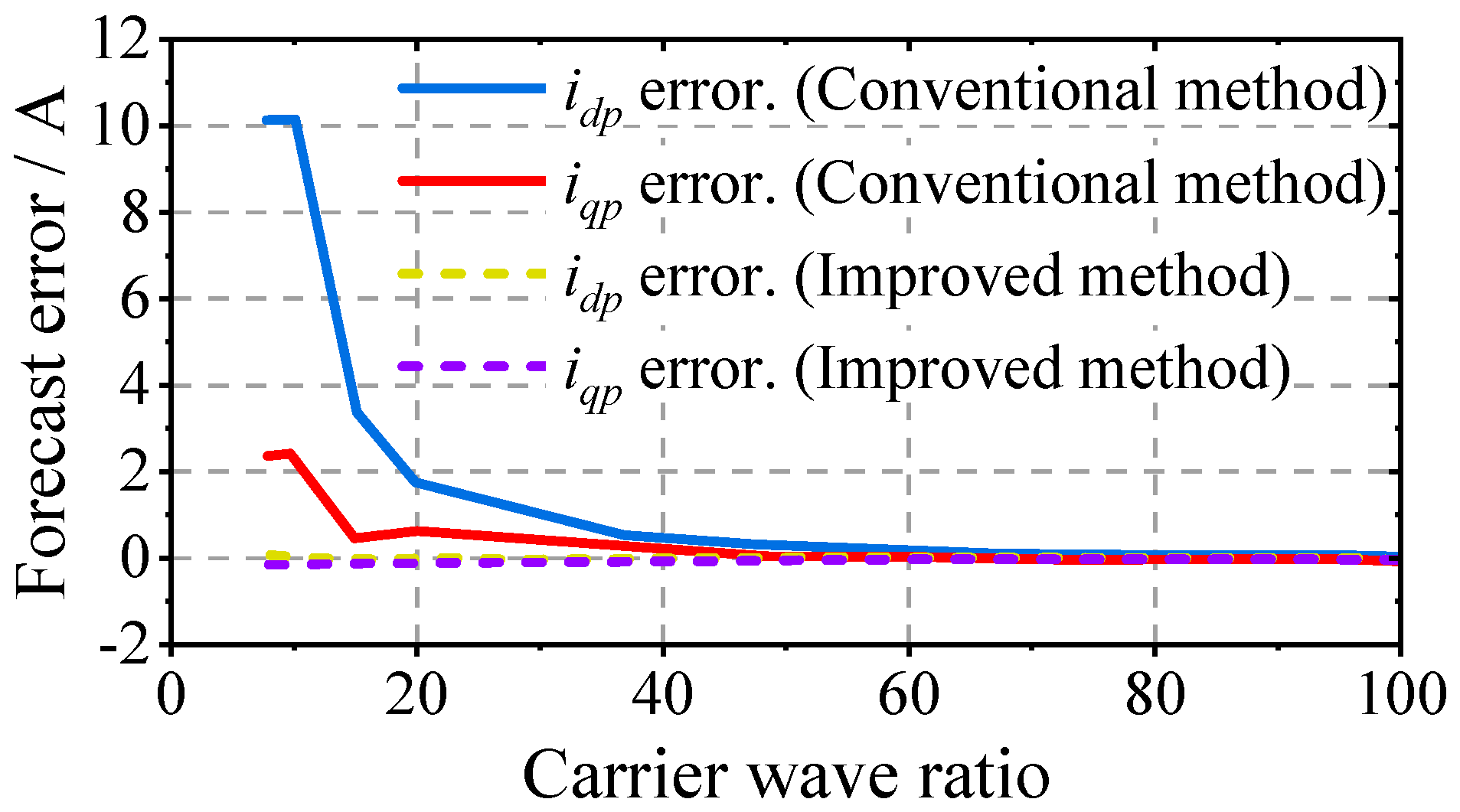
A comparison of the
d and
q axis current prediction errors under two deadbeat predictive current control methods at different carrier ratios is presented in
Figure 7. The prediction error is calculated using the following formula (taking the average value over 1 s in steady state).
When the carrier ratio is above 40, both deadbeat control strategies show similar current prediction accuracy, which remains within an acceptable range. When the carrier ratio is between 15 and 40, the d and q axis current errors of the conventional DPCC strategy gradually increase as the carrier ratio decreases, while the improved DPCC maintains high prediction accuracy. When the carrier ratio falls below 15, the prediction errors of the conventional DPCC increase sharply, making it impossible to maintain stable machine operation. In contrast, the improved DPCC still demonstrates high prediction accuracy and maintains satisfactory control performance.
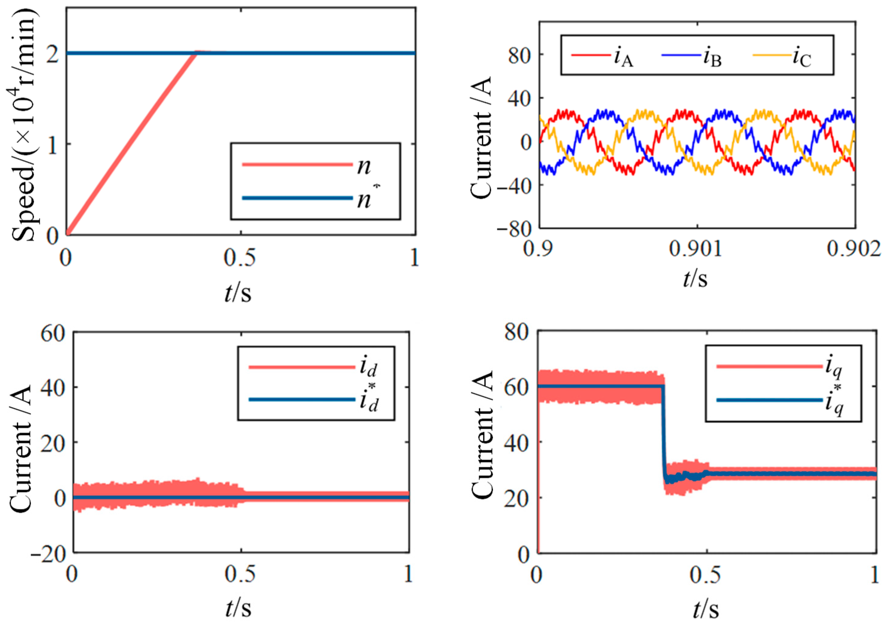
Furthermore, to verify the performance of the proposed method under high-speed and low carrier ratio conditions, simulations were carried out for such scenarios. The simulation results for a high-speed PMSM with 4 pole pairs operating at 20,000 r/min with a control frequency of 20 kHz, corresponding to a carrier ratio of 15, are shown in
Figure 8. The simulation results are consistent with those under low-speed and low carrier ratio conditions, demonstrating the effectiveness of the proposed method in high-speed and low carrier ratio applications.
5. Experimental Result
The experimental validation presented in this section not only verifies the effectiveness of the proposed method but also demonstrates its distinct advantages over existing predictive control strategies. Most notably, the maintained stability at carrier ratios as low as 7.4 represents a significant extension of the practical operating range achievable with DPCC, addressing a critical limitation in high-speed drive applications. To validate the feasibility of the theoretical analysis and the effectiveness of the proposed method, an experimental platform was established as shown in
Figure 9. The platform mainly consists of a drive unit, a three-phase machine, and a load machine. The core of the drive control unit employs a DSP (TMS320F28377D) plus FPGA architecture. The parameters of the target PMSM are listed in
Table 1.
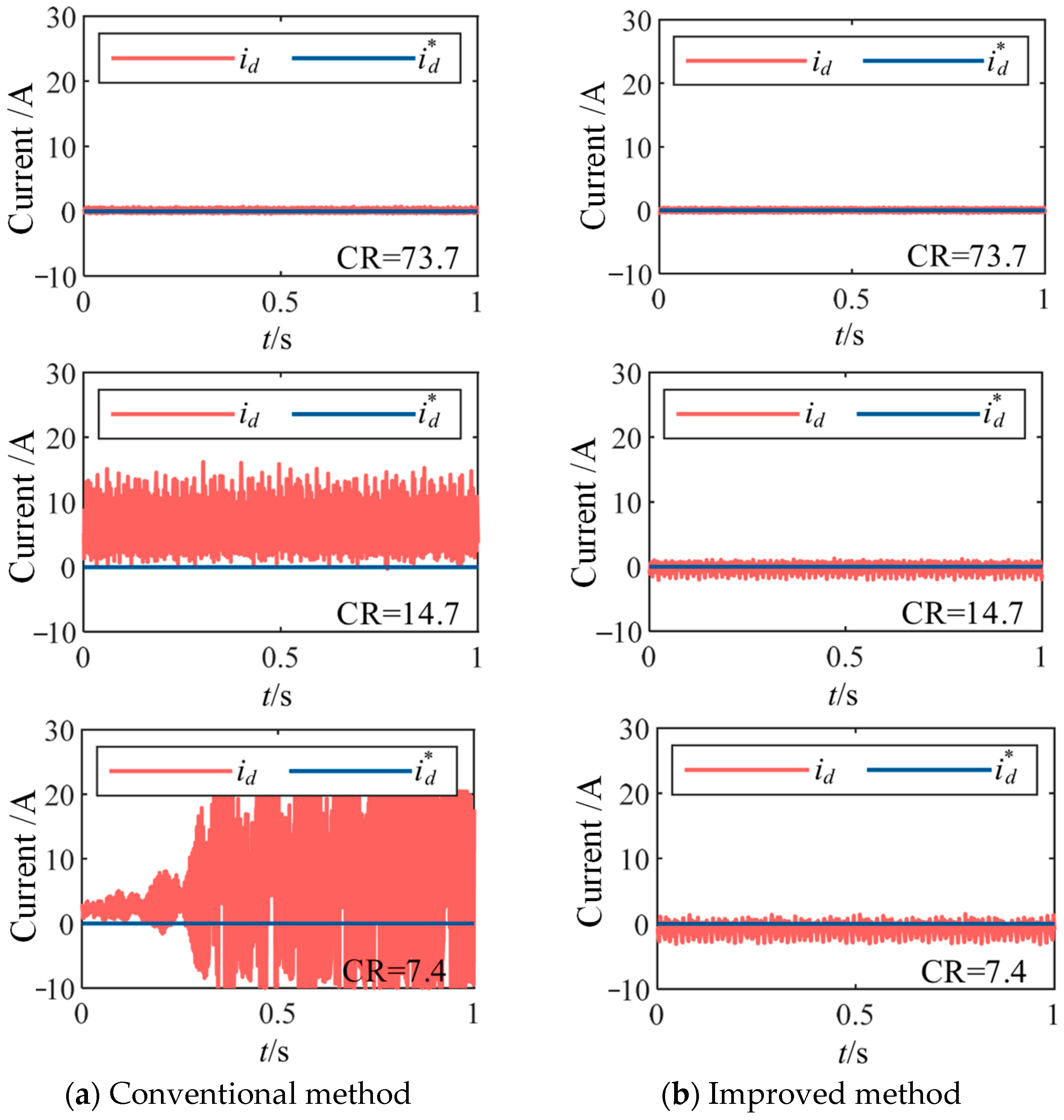
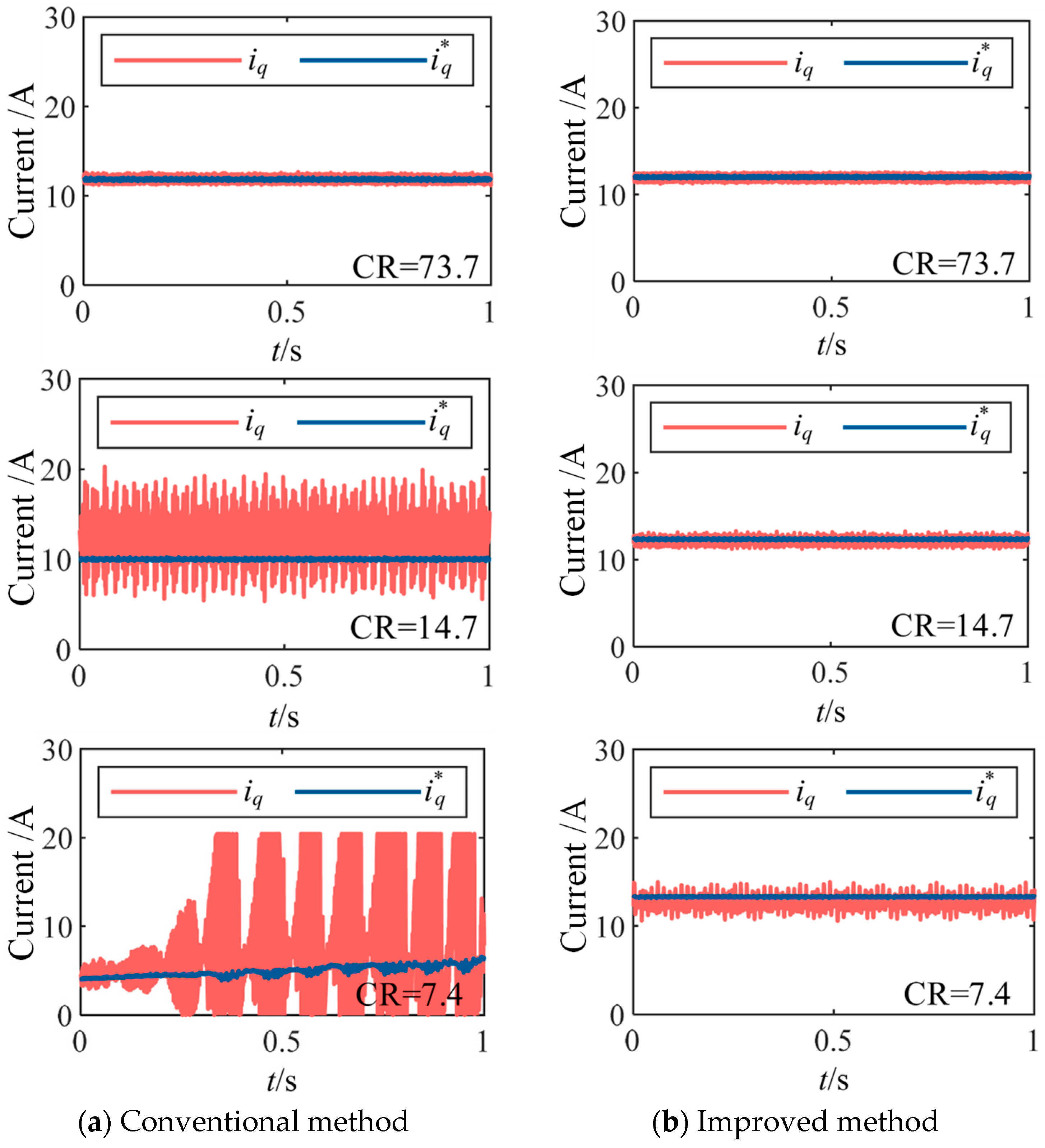
To verify the effectiveness of the proposed algorithm, steady-state experiments under different carrier ratios were conducted using both conventional and the proposed methods. The machine was maintained at the rated speed of 370 r/min, with control frequencies set to 10 kHz, 2 kHz, and 1 kHz, corresponding to carrier ratios (CR) of 73.7, 14.7, and 7.4, respectively. The comparative waveforms of the
d and
q axis currents under conventional DPCC and improved DPCC algorithms are shown in
Figure 10 and
Figure 11, respectively. It can be observed that at higher carrier ratios, both conventional and improved DPCC exhibit satisfactory tracking performance for the
d and
q axis currents. As the carrier ratio decreases, the
d and
q axis currents under the conventional method gradually deviate from the reference values and even oscillate severely, leading to a complete loss of control. In contrast, the proposed method maintains accurate tracking of the reference currents without steady-state error, although the current ripple increases slightly and the pulsation of
d and
q axis currents slightly amplifies as the carrier ratio decreases.
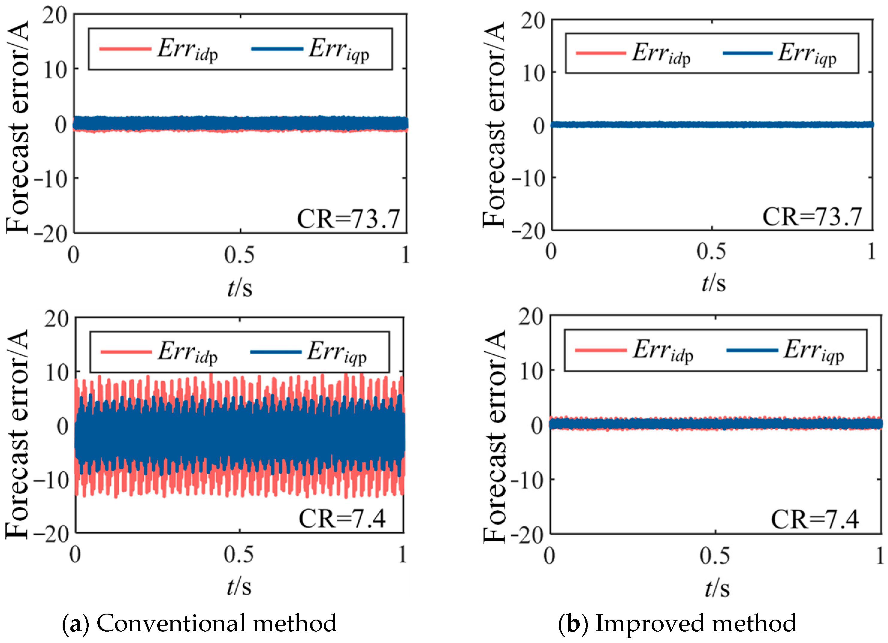
In deadbeat control, both tracking error and prediction error reflect the accuracy of the predictive model. Therefore, based on the tracking error experiments, the prediction errors of the
d and
q axis currents under the two DPCC strategies were further compared at control frequencies of 10 kHz and 2 kHz. The experimental results are shown in
Figure 12. It can be seen that whether at high or low carrier ratios, the proposed method yields smaller prediction errors in the
d and
q axis currents compared to the conventional method, and the errors remain nearly zero.
To separately verify the effectiveness of the stator voltage equation considering rotor magnetic field orientation error and the multi-coordinate synchronization algorithm in the proposed method, the controller first operated with the conventional DPCC algorithm. After the system reached steady state (
t = 2.1 s), the multi-coordinate synchronization algorithm was activated. Then, after 2.5 s (
t = 4.6 s), the current prediction model and command voltage calculation model based on the improved stator voltage equation were enabled, constituting the complete proposed method. The experimental results are shown in
Figure 13.
The results indicate that with the conventional method, both the tracking performance and prediction error of the d and q axis currents are significant. After activating the multi-coordinate synchronization algorithm, the prediction error is greatly reduced, and the fluctuation of the d and q axis currents decreases significantly, approaching the reference values more closely, though steady-state error still exists. After enabling the improved stator voltage equation-based models, the prediction error is further reduced, tracking accuracy is improved, and almost no steady-state error remains.
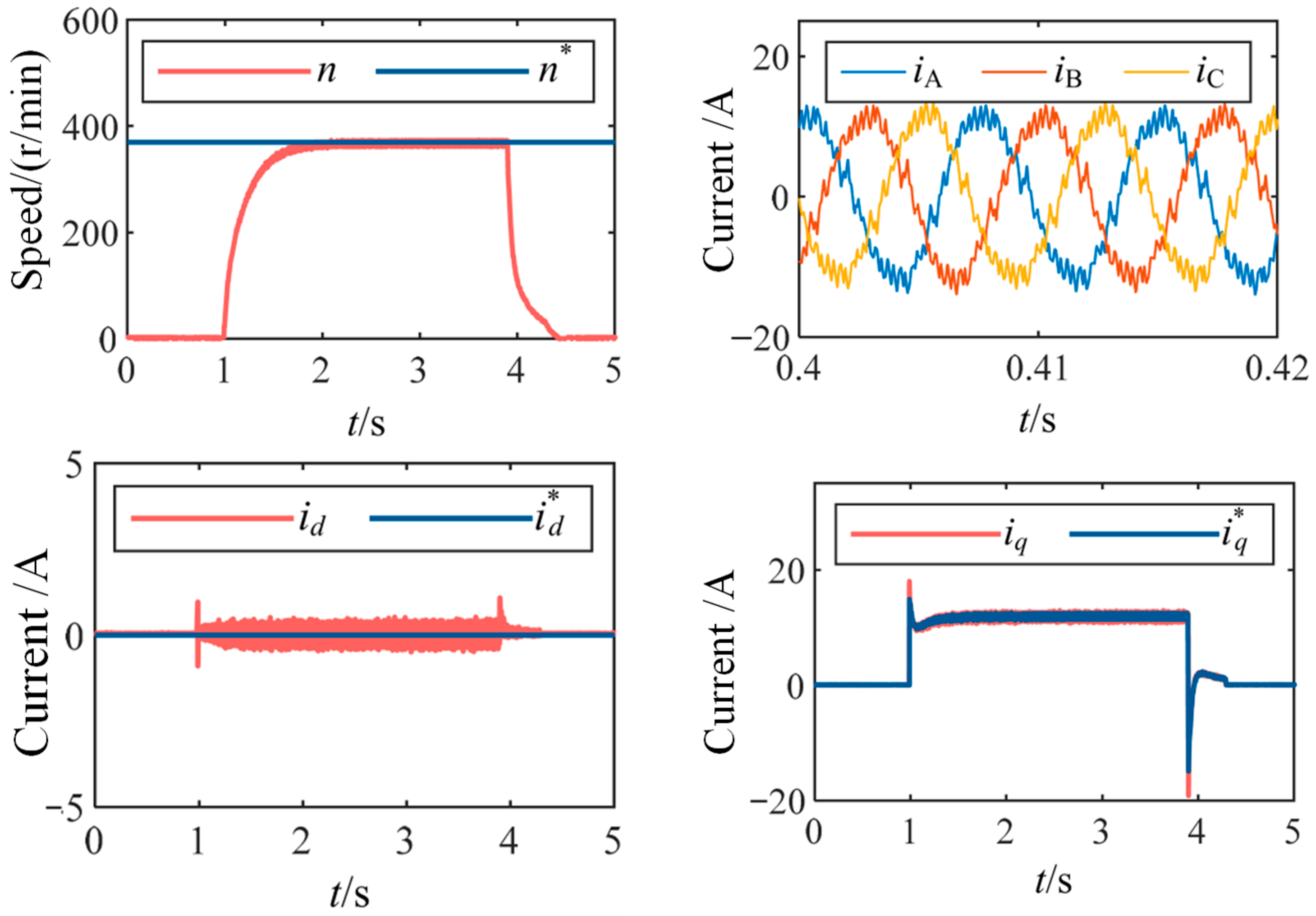
To validate the control precision of the proposed method during dynamic acceleration and deceleration processes, start-stop experiments were conducted under low carrier ratio conditions. The speed, phase current, and
d and
q axis current waveforms during the process in which the machine is started under load, accelerated to the rated speed of 370 r/min, and then decelerated to zero speed, all under a control frequency of 2 kHz, are shown in
Figure 14. The results demonstrate that under low carrier ratio conditions, the proposed method maintains complete decoupling of the
d and
q axis currents during both acceleration and deceleration, with accurate tracking of the reference values, indicating high control precision even during transient processes.
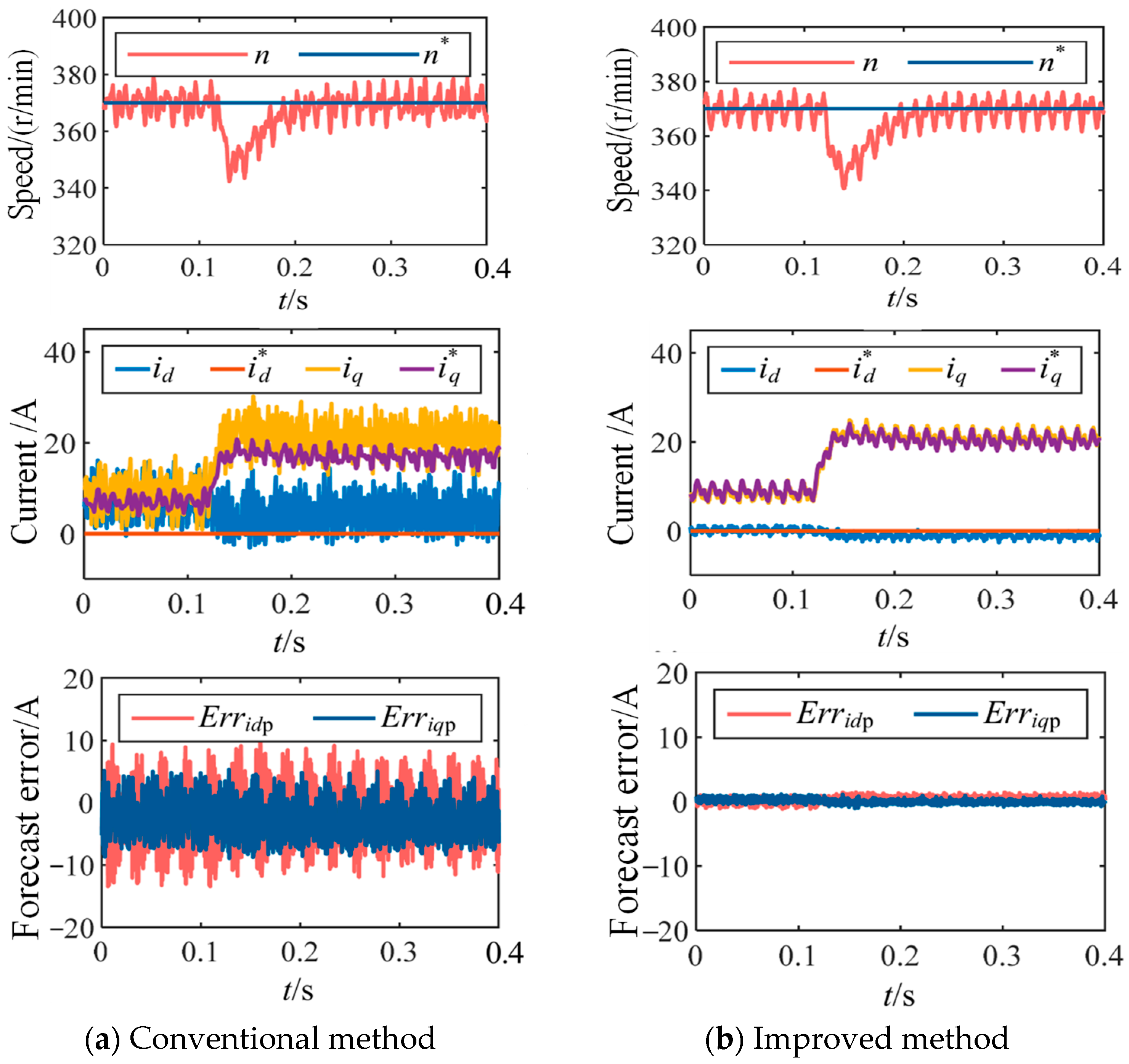
Additionally, to verify the system stability and control performance of the proposed method under load variations, a sudden load increase experiment was conducted under low carrier ratio conditions. When the machine was operating at the rated speed of 370 r/min with a control frequency of 2 kHz, a 150% load step was applied (from 47 N m to 119 N m). The comparative experimental results using the conventional and proposed methods are shown in
Figure 15. The results show that with the conventional method, the tracking performance of the
d and
q axis currents is poor and unstable before and after the load change, indicating that operating conditions significantly affect algorithm performance, and the prediction error is large. In contrast, the improved method maintains nearly zero prediction error before, during, and after the load transient, while preserving high tracking accuracy of the
d and
q axis currents. This confirms that the proposed method maintains high prediction accuracy and good control performance during dynamic processes and under various operating conditions, with minimal influence from load variations.
As demonstrated in the experimental results, the proposed method maintains stable operation and accurate tracking even at extremely low carrier ratios (down to 7.4), where both conventional DPCC and the reference methods exhibit significant performance degradation. Specifically, under CR = 7.4 conditions, our method achieves current THD below 8.2%, outperforming the adaptive method (THD > 12.5%) and the robust control approach (THD > 15.3%). More importantly, the systematic addressing of multi-coordinate computational errors provides inherent advantages in dynamic response characteristics, as evidenced by the superior performance during start-stop transitions and load variations shown in
Figure 14 and
Figure 15.
The comparative analysis confirms that the method not only resolves the specific limitations of conventional DPCC but also offers competitive advantages over other advanced predictive controllers, particularly in the challenging low carrier ratio regime that is critical for high-speed drive applications.
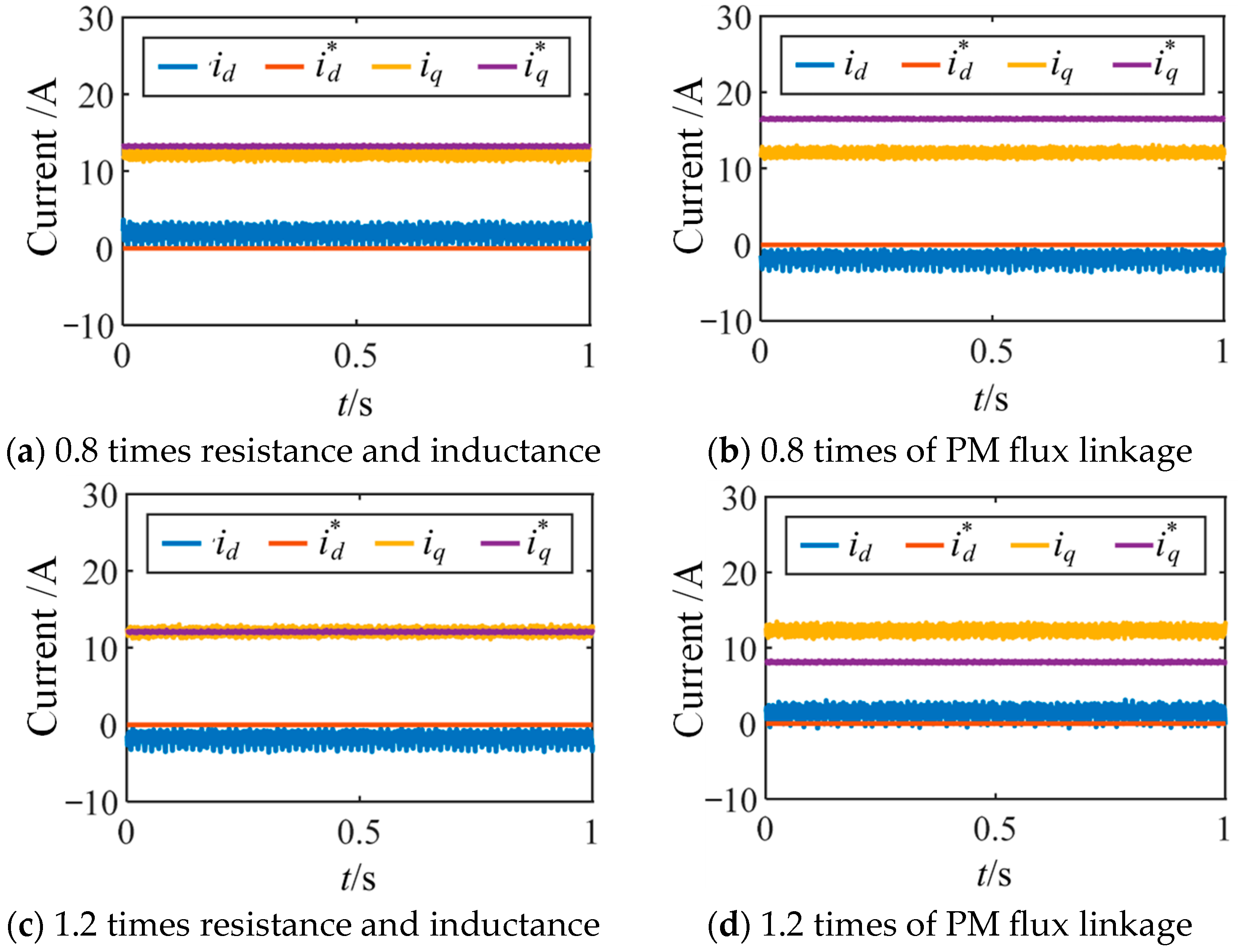
To verify the robustness of the proposed method against discrepancies between actual and nominal machine parameters, experiments were conducted under machine parameter mismatch conditions, including stator resistance and inductance mismatch, as well as rotor permanent magnet flux linkage mismatch. At the rated speed of 370 r/min and a control frequency of 2 kHz, the stator resistance and inductance parameters and the rotor permanent magnet flux linkage parameter in the controller were set to 0.8 and 1.2 times their calibrated values, respectively. The experimental results are shown in
Figure 16. The results indicate that compared to variations in the rotor permanent magnet flux linkage, changes in the stator resistance and inductance parameters have a smaller impact on the performance of the proposed method.
