Article

The Potential of Using Birotor Machines in Modern Transport Means

1
Department of Cars and Carriage Facilities, National Transport University, Kyrylivska Street 9, 04071 Kyiv, Ukraine
2
Department of Mechanics and Machine Design, Ukrainian State University of Railway Transport, 7 Feuerbach Square, 61050 Kharkiv, Ukraine
3
Institute of Automotive Engineering, Faculty of Mechanical Engineering, Brno University of Technology, Technická 2896/2, 616 69 Brno, Czech Republic
*
Author to whom correspondence should be addressed.
Machines 2025, 13(11), 994; https://doi.org/10.3390/machines13110994
Submission received: 26 September 2025 / Revised: 22 October 2025 / Accepted: 27 October 2025 / Published: 29 October 2025
(This article belongs to the Section Machine Design and Theory)

Abstract

The transport sector requires compact, reliable, and energy-efficient power units for modernization of road, rail, maritime, and aerial systems. Conventional piston and rotary machines often face limitations related to vibration, sealing losses, and manufacturing complexity. This study investigates birotor machines (BM), a class of positive-displacement devices combining synchronized rotation of the rotor and housing. This configuration ensures smooth kinematics, near-complete dynamic balance, and simplified design. The working principle enables continuous volumetric transformation with reduced friction and leakage, enhancing efficiency and durability. Using generalized mathematical models (GMM) developed through statistical experimental design, optimal geometric parameters were determined with a root-mean-square error below 3%. A prototype birotor compressor (BC) designed for subway rolling stock achieved equivalent output performance (0.43 m3/min at 0.8 MPa) with 82% efficiency and a mass reduction from 130 kg to 32 kg. Comparative simulations and preliminary testing of BM-based internal combustion engines (BRICE) demonstrated 3–4 times smaller and lighter units with improved reliability and environmental characteristics. The results confirm that BM technology provides a feasible and manufacturable alternative to conventional designs, suitable for integration into next-generation transport and unmanned vehicle systems.

1. Introduction

The transport sector is a fundamental component of the economy. A well-developed infrastructure—including highways, extensive railway networks, airports, air routes, and cargo terminals—provides the necessary conditions to meet user demand and support business development. Maritime and river transport also play a crucial role, enabling the movement of goods and passengers. Sea shipping, in particular, remains central to both international and domestic logistics. Despite its importance, the transport industry often meets only basic quantitative needs, while falling short in service quality and in integration with the trans-European transport network. Existing systems—road, rail, sea, and river—require substantial modernization or even complete replacement. At the same time, there is a pressing need for modular solutions that enable the construction of transport vehicles with improved technical and economic performance, suitable for both civilian and military applications. An analysis of recent studies confirms the need for new structural solutions in both civilian and military applications. Addressing this challenge requires a comprehensive approach that combines advanced design concepts with modern materials capable of meeting demanding operational and long-term performance requirements for transport modules. In particular, the replacement of outdated internal combustion engines and compressors is a pressing priority in the marine and river transport sectors. Modern transport technologies require compact, high-performance units that can substantially improve the technical and economic efficiency of road, rail, maritime, and river systems.
A significant contribution to frequency analysis of non-axisymmetric rotating structures was presented in a study that introduced a computationally efficient method validated on a birotor system [1]. In the field of unmanned aerial vehicles (UAVs), the design of a small UAV with a birotor configuration was reported, combining stability with low structural weight and supported by effective control algorithms [2]. Energy-related issues in railway transport have been investigated through studies on capacitive energy storage [3,4], which demonstrated potential to reduce peak power demand and operational costs. Safety aspects were addressed in the analysis of dynamic loads on tank containers transported by railway ferries [5], while another study explored ways to extend the service life of worn-out railway wagons [6]. The importance of material parameters for operational reliability was highlighted in experiments on the elasticity of steel-cord conveyor belts [7]. Diagnostics of electric drives also form an important research area. The Park’s Vector Method has been successfully applied for rotor condition monitoring [8], and a structural model of an embedded real-time diagnostic system for vehicle drives was developed [9]. A large body of work is dedicated to aerodynamic modelling and optimization of propellers and rotors [10,11,12,13,14,15,16,17,18,19,20,21,22,23,24,25,26,27,28,29]. Examples include an extended blade-element model for contra-rotating configurations [10], the design of rotors for agricultural UAVs [11], studies on acoustic properties of coaxial rotors [13], and optimization of marine propellers to reduce fuel consumption [16,17]. Collectively, these studies demonstrate opportunities to improve efficiency, reduce noise, and enhance propulsion stability. Specific UAV-related contributions include the development of vision-based position control systems [21] and investigations of rotor tilt effects on gust rejection [26], both of which significantly improve manoeuvrability. Aeromechanics of compound helicopters were examined in [27], while ducted and coaxial rotor configurations were analysed in [28,29], providing versatile design methodologies for aviation. The scope of research extends further to statistical modelling of multiphase flow environments [30], optimization of composite launch vehicle structures [31], hybrid communication systems for unmanned surface vessels [32], and integration of renewable energy in maritime transport [33]. Fluid-related studies addressed viscous flow behaviour under boundary variations [25] and calibration methods to improve velocity measurements in turbulent ventilation flows [26]. This review highlights that, despite extensive research on aerodynamics, diagnostics, and energy efficiency, the potential of birotor machines in modern transport remains underexplored. Most existing studies are theoretical or simulation-based, while practical and experimental applications are still limited. This gap hinders the wider adoption of technologies that could significantly contribute to more economical and environmentally sustainable transport systems. Recent studies further demonstrate the progress in hybrid propulsion and intelligent control systems [34,35,36], emphasizing the need for compact and efficient energy devices compatible with unmanned and autonomous platforms.
Additionally, recent developments in multi-unmanned vehicle cooperative encirclement control based on bidirectional long short-term memory and mixed reward functions [37] highlight the growing importance of advanced control architectures, providing context for the integration potential of BM technology.

2. Materials and Methods

2.1. Structural Design of Birotor Machines

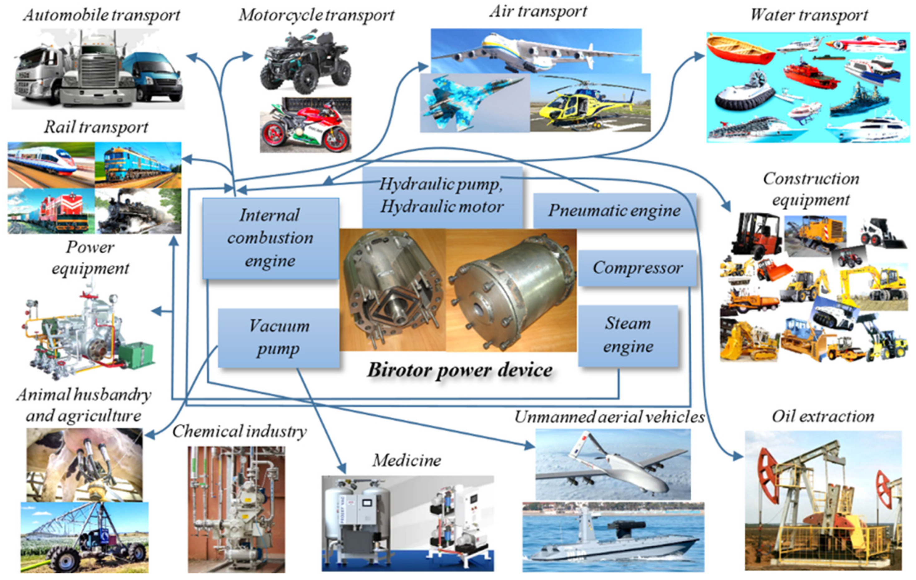
The aim of this article is to highlight promising directions for the application of birotor machines (BM) (Figure 1) as components of technical systems across various sectors of the national economy under modern transport conditions. Scientific and engineering research conducted by the authors in the development of BM has demonstrated [1,2,7,10] that, due to their structural design, these machines combine the advantages of both piston and rotary volumetric machines. These advantages include:
  • reliable sealing of working chambers (ensuring high durability),
  • excellent dynamic balance (resulting in low vibration levels),
  • minimal requirements for material quality,
  • compact size and low weight,
  • ease of manufacturing,
  • low production cost,
  • high maintainability, and
  • no need for additional balancing mechanisms.
A birotor machine (Figure 2) features a mechanism in which an axis with two eccentric journals—offset relative to each other—remains stationary. Each journal serves as the rotational axis for the housing (1) and the rotor (2), respectively. The housing is a cylindrical shell enclosed at both ends with side covers. The rotor, located inside the housing, has flat end faces (3) and parallel grooves (4) on its ends. The cavity between the housing and the rotor is divided into sealed working chambers by shutters (5), which are installed in radial grooves (6) of the housing and connected to the rotor via sliders (7). Torque is extracted from the rotating housing. For the BM to operate, a minimum of two shutters is required, while the maximum number is theoretically unlimited.
Such a birotor machine can be configured to operate as a four-stroke or two-stroke internal combustion engine, a hydraulic supercharger (pump), a hydraulic motor, a high-pressure fuel pump, a pneumatic supercharger (compressor), a pneumatic or steam motor, or a vacuum pump.
Research has demonstrated that birotor machines (BM) can be effectively utilized as hydraulic superchargers (pumps) [5] or hydraulic motors, achieving efficiencies up to 96%. These machines are suitable for integration into hydraulic drive systems across a wide range of applications, including water, sea, and river transport; road and railway vehicles; construction and lifting equipment; agricultural machinery; ground vehicle transmissions; and hydraulic systems in aircraft and rotorcraft.
Currently, axial-piston and radial-piston devices are commonly used as hydraulic pumps and motors. However, these conventional systems are highly complex, heavy, bulky, expensive, and difficult to repair. For instance, the axial-piston hydraulic machine MH-250/100 (M+S Hydraulic PLC, Kazanlak, Bulgaria), used in diesel locomotives to drive radiator cooling fans, weighs 79 kg and has dimensions of 470 × 220 × 152 mm (volume: 0.16 m3). In contrast, a rotary hydraulic machine with equivalent performance weighs only 21 kg and measures 190 × 190 × 186 mm (volume: 0.067 m3).
Moreover, axial-piston machines cannot be repaired in standard depot conditions and require specialized aircraft repair facilities. In comparison, BM-type hydraulic machines are significantly easier to maintain and can be serviced directly within the depot, offering a practical and cost-effective alternative.
The integration of birotor machines (BM) as components of vehicle hydraulic transmissions—specifically as hydraulic pumps and motors—eliminates the need for complex and costly mechanical systems such as clutches, gearboxes, differentials, and cardan shafts. Hydraulic systems allow for flexible placement of the power unit with a hydraulic pump anywhere within the vehicle, transmitting torque to hydraulic motors or motor-wheels via fluid through pipelines and hoses. Due to their compact size and low weight, BM-based hydraulic transmission systems represent a highly promising direction for future development.
The use of BM as compressors [14,15,16,17,18,19], in place of conventional piston compressors commonly used in vehicles, offers significant advantages. These include a 3–5-fold reduction in weight and dimensions, and a 2–3-fold decrease in cost. Research conducted by the authors has shown that piston compressors suffer from several drawbacks: large mass and volume, high vibration levels, and excessive power consumption. These issues stem from the inherent design of crank mechanisms, which involve reciprocating motion of heavy components, leading to substantial inertial loads and imbalance. Reducing vibration in such systems is a complex engineering challenge, often requiring major design modifications aimed at balancing these inertial forces.
In contrast, rotary compressors—such as birotor compressors (BC)—offer superior performance in terms of weight, size, and vibration characteristics. For example, Table 1 presents specifications of existing piston compressors [18,19,20,21] used in rolling stock, while Table 2 outlines projected specifications for BCs intended for air supply systems in the same applications.
A working prototype of a BC for subway cars has already been developed. It features a working volume of 456 cm3, delivers a pressure of 0.8 MPa (8 atmospheres), and achieves a flow rate of 0.43 m3/min at 1500 rpm. The unit weighs 32 kg and has dimensions of 220 × 228 × 325 mm. In comparison, the currently used piston compressor ЭK-4 weighs 130 kg and measures 520 × 583 × 465 mm. Bench testing has been completed, and design documentation for an improved version of the compressor has been prepared [4,9].
These findings underscore the importance of continued research and development aimed at reducing the vibration, weight, size, and energy consumption of reciprocating compressors.

2.2. Birotor Machines in Internal Combustion Engines Design

BM technology is also relevant for use in internal combustion engines (ICE), both two-stroke and four-stroke, particularly for compact autonomous power units in various sectors: marine (especially sea transport), aviation, land transport, and portable mechanical tool systems [5,8]. This approach can reduce weight and size by 3–5 times, lower costs by 2–4 times, and improve reliability, efficiency, and service life.
Structurally, ICEs based on birotor energy devices differ from conventional designs by employing simultaneous rotation of both the housing and the rotor. This enables centripetal movement of the working mixture and cooling air, efficient unidirectional slit scavenging, and effective sealing of working chambers—all without the need for a traditional ignition system.
It is important to note that birotor internal combustion engines (BRICE) offer several advantages over conventional rotary and piston internal combustion engines, including:
  • Simplicity of design—due to the use of geometrically simple components.
  • High manufacturability—components can be produced without the need for specialized equipment.
  • Compact dimensions—BRICE units are 3–4 times smaller than equivalent piston-type engines.
  • Low material consumption and weight—resulting in lighter and more efficient systems.
  • High reliability and durability—achieved through the use of simple rotational motion of many components on rolling bearings and reliable sealing elements, each of which moves slowly during one engine revolution—significantly less than the rotor circumference.
  • Simplified ignition system—no distributor is required, unlike in conventional rotary engines.
  • Self-cooling capability—eliminating the need for an additional cooling system, which is standard in traditional rotary engines.
  • Excellent maintainability—heavily loaded components can be easily replaced as modular blocks during maintenance.
  • Significantly lower weight-to-power ratio—compared to piston engines.
  • Environmental friendliness—due to superior sealing of working chambers, which reduces the risk of harmful emissions.
  • Low production cost and capital investment—making BRICE an economically attractive solution.
In addition to the previously mentioned advantages, it is important to emphasize that in the BRICE, all moving components perform purely rotational motion around their respective axes. This design feature allows for an increase in engine speed without a corresponding increase in engine weight. Moreover, the reduced mass of the rotating parts enables the engine to accelerate more rapidly to higher initial speeds, which enhances its efficiency during dynamic operation.
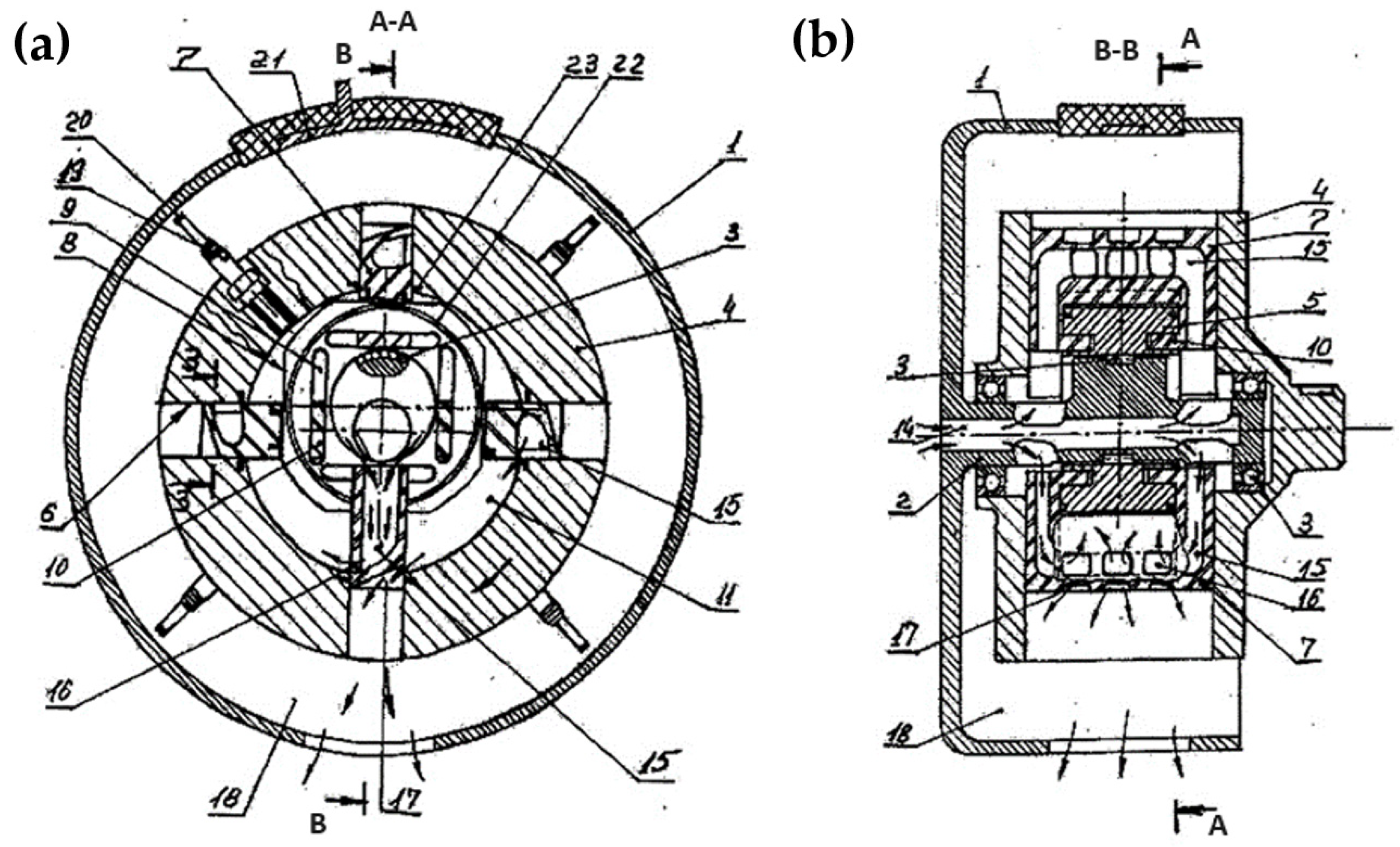
Figure 3 illustrates the general layout of a two-stroke BRICE. The engine consists of a cylindrical block with an integrated eccentric axis. On the eccentric journals of this axis, rotation supports are mounted, which carry the housing. Inside the housing, a rotor is positioned. The housing contains radial grooves in which sliders are installed with the ability to move radially. On the outer surface of the rotor, flat faces are formed in the areas where it contacts the sliders, and tangentially aligned rectangular grooves are machined parallel to these faces. Sliders, which are integrated with the shutters, are able to slide tangentially within these grooves. The space between the housing and the rotor forms sealed working volumes.
Within the eccentric axis, a receiver is integrated, which connects to intake manifolds leading into internal cavities within the shutters. These manifolds are further connected to intake ports located on one of the shutter walls. Exhaust ports are positioned at the ends of the shutters and are connected via the radial grooves to an exhaust manifold situated between the housing and the block. Each working volume is equipped with a spark plug, which is connected to a current-collecting brush. An electrically insulated current supply segment is mounted on the block in the ignition zone. Sealing of the working volumes is ensured by spring-loaded sealing rings and plates. Additionally, splines in the radial grooves engage with corresponding spline grooves in the shutters to maintain alignment and sealing integrity.
The BRICE operates on a two-stroke cycle. A supercharger injects the working mixture into the receiver, from where it flows through the intake manifolds and intake ports into the working volumes. Within these volumes, the mixture is compressed and ignited by the spark plugs. As the housing and rotor rotate synchronously, the exhaust ports open, allowing combustion gases to be expelled into the exhaust manifold. The intake and exhaust ports open and close periodically at the edges of the housing. Electrical current is supplied from the insulated segment on the block to the spark plugs via the brushes. The sealing of the working volumes is maintained by the spring-loaded sealing elements and the spline-guided movement of the shutters.
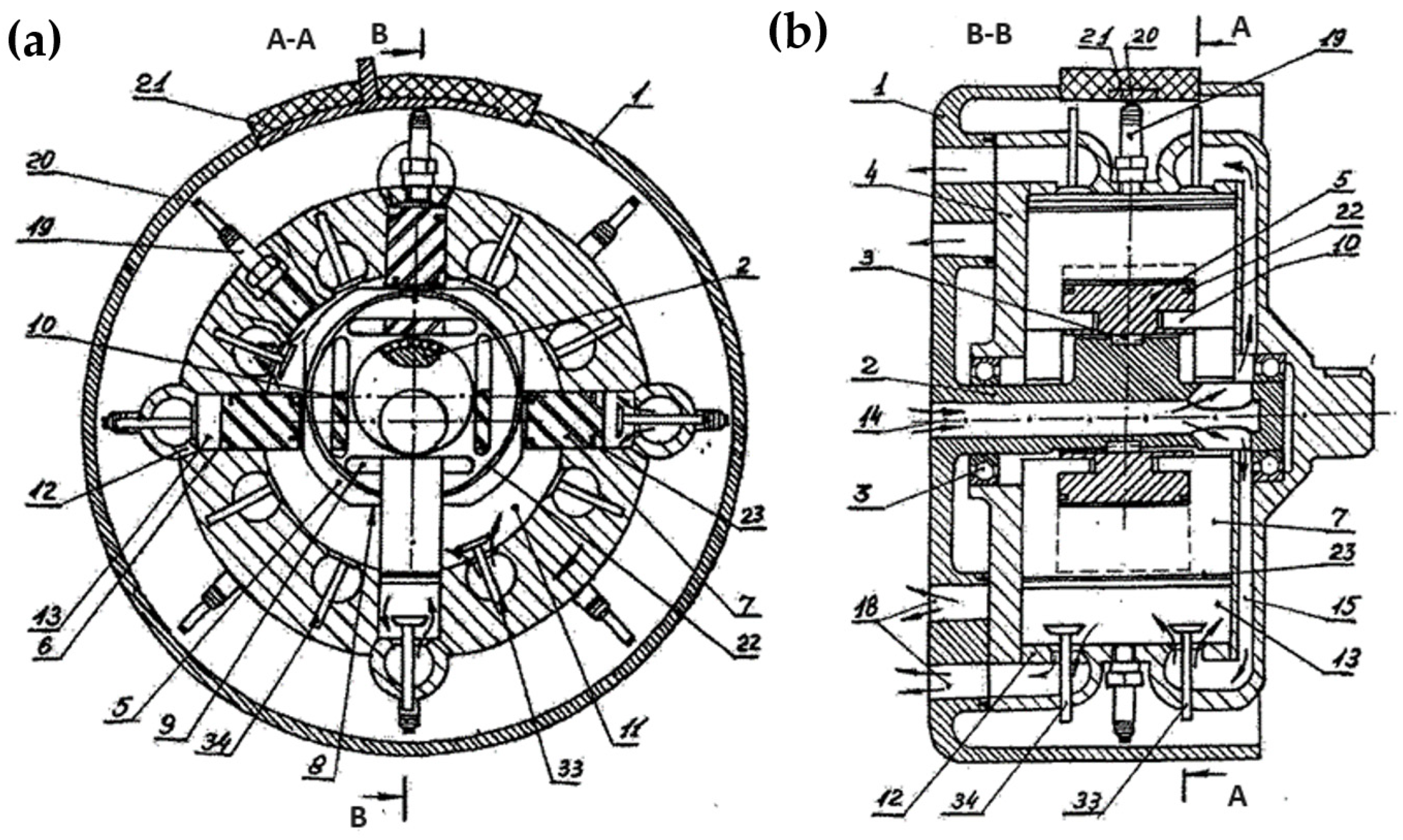
Figure 4 shows the general view of a four-stroke BRICE, which contains: a cylindrical block 1 with an eccentric axis 2 made together with it, on the eccentric necks of which a housing 4 is installed on the rotation supports 3, in the inner volume of which the rotor 5 is located.
The engine consists of a cylindrical block with an integrally formed eccentric axis. On the eccentric journals of this axis, a housing is mounted via rotation supports, and within its internal volume, a rotor is positioned.
Inside the housing, radial grooves are machined to accommodate sliders capable of radial movement. Where these sliders contact the rotor, flat faces are formed on its outer surface, and tangentially aligned rectangular grooves are positioned parallel to these faces. Within these grooves, tangentially sliding sliders are installed, which are structurally integrated with the shutters. The space between the housing and the rotor forms the primary working volumes. The radial grooves of the housing are sealed externally with plugs, which also define secondary working volumes.
A receiver is integrated within the eccentric axis and connects to intake manifolds located in one of the housing walls. Intake valves are installed in both the primary and secondary working volumes, allowing the working mixture to enter. Exhaust valves are also present in these volumes and connect to exhaust manifolds embedded in the block. Each working volume contains a spark plug equipped with a current-collecting brush, and an electrically insulated current supply segment is mounted on the block in the ignition zone. Sealing of the working volumes is ensured by spring-loaded sealing rings and plates.
The engine operates on a four-stroke cycle. As the housing rotates, the working mixture is drawn into the working volumes through the receiver, intake manifolds, and intake valves, where it is compressed and ignited by the spark plugs. As rotation continues, the exhaust valves open, allowing combustion gases to be expelled into the exhaust manifolds. The timely opening and closing of the intake and exhaust valves is controlled by a gas distribution mechanism.
Electrical current is supplied from the insulated segment on the block to the spark plugs via the current-collecting brushes. Synchronization of the housing and rotor rotation is achieved through the sliders, which move radially within the radial grooves and tangentially within the grooves of the rotor. The edges of the shutters move with slight clearance along the flat faces of the rotor, and sealing is maintained by spring-loaded plates.
Torque is transmitted from the pressure of the combusted mixture in the primary working volumes through the shutters, which press against the radial grooves of the housing, from which the engine’s output torque is extracted. In the secondary working volumes, force is transmitted via the tangential component of pressure acting on the walls of the radial grooves.
A key challenge in the development of BRICE lies in the optimal selection of its design parameters to minimize weight and size. One promising approach is the use of mathematical experiment planning methods, which enable the construction and analysis of generalized mathematical models (GMM) [12].
As an example, the results of computational studies are presented below to determine the key design parameters of birotor compressors. These compressors are designed to match the performance and outlet pressure characteristics of existing compressor models used in modern railway rolling stock (e.g., KT-7, ПK-3.5, BB-1.5/9, ЭK-7Б, ЭK-4) [3,4,5,6,7,8,9].
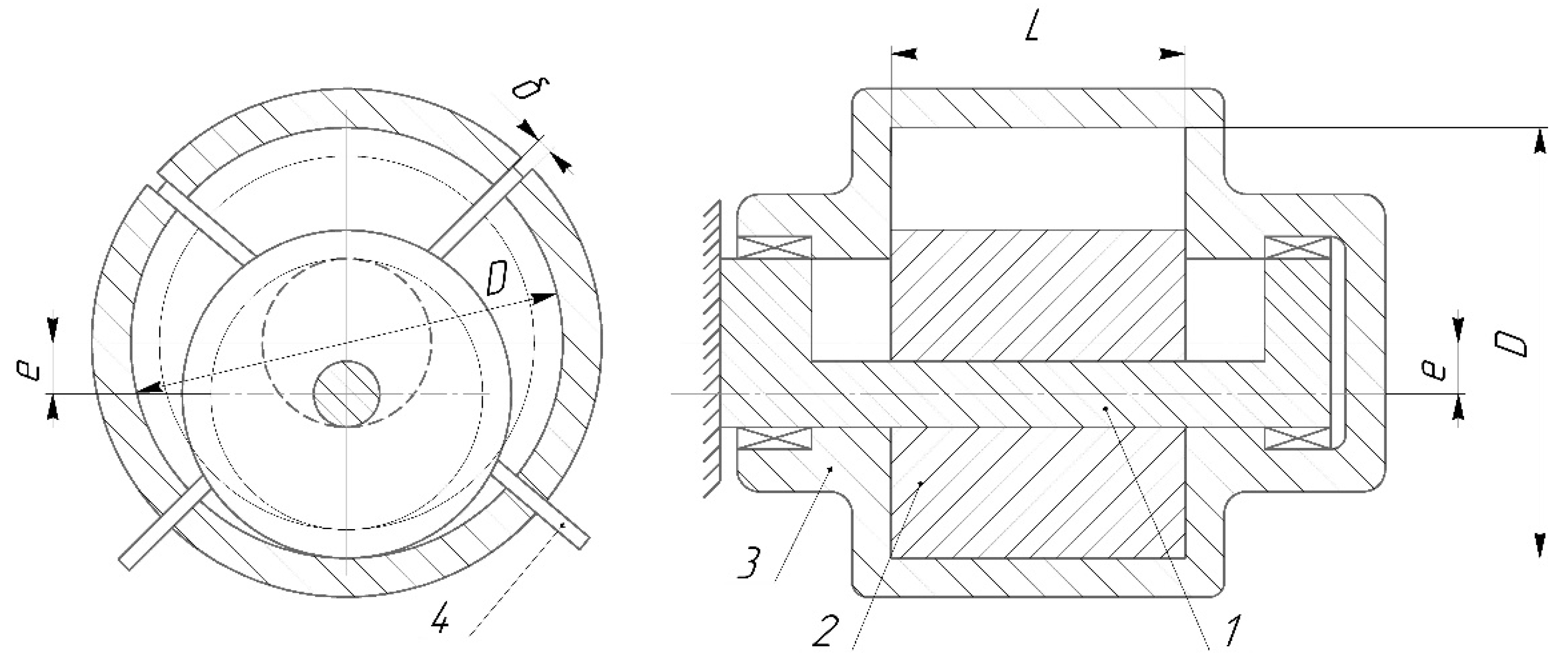
The primary design parameters of birotor compressors include (see Figure 5):
  • D—diameter of the rotating housing,
  • L—length of the compressor cylinder (longitudinal dimension of the working chambers),
  • e—eccentricity (distance between the rotational axes of the housing and the rotor),
  • δ—thickness of the shutters,
  • z—number of shutters (i.e., number of working chambers),
  • n—rotational speed.
In evaluating the performance of birotor compressors (BC) for various applications, it is advisable to consider the following indicators:
  • Actual volumetric flow rate Q,
  • Total internal volume of the compressor VΣ, and
  • Shaft power N (i.e., the required power input from the electric drive).
The actual volumetric performance Q of the birotor compressor is determined using the following formula:
Q = 2 · L · π · D · e 2 e 2 l · δ · z · n · λ ,
where l—is the length of the shutter; λ—feed rate (it is accepted λ = 0.53)
The values of the total structural volume VΣ of the new BC are determined by the formula
V Σ = π D m a x 2 L m a x 4 ,
where are Dmax, Lmax—the maximum dimensions of the BC structure (accepted: Dmax = 2.667, Lmax = 3.6). It is advisable to determine the power on the shaft of a new BC (as a rotary machine) using the formula for isothermal gas compression
N = A · R · T · ln p i n g p s u c 860 · η i s · Q · γ ,
where are T—intake air temperature (accepted in research T = 293 K); R—gas constant (for air R = 29.27 kGm/(kg∙deg)); ping, psuc—injection and suction pressure; γ—air density at intake (at t = 20 °C is γ = 1.16 kg/m3); ηis—isothermal efficiency (accepted ηis = 0.55).
It should be noted that the following were chosen as parameters that directly affect the values of the indicators: the diameter of the moving body D, the length of the compressor cylinder L and the frequency of rotation of the BC shaft n. At the same time, the experience of exploratory studies of the BC mechanical system showed that it is advisable to accept eccentricity in the calculations e = 0.12 D, the thickness of the shutters δ = e, and the number of dampers (the number of working chambers of the compressor) z = 4. As it was mentioned above, it is advisable to choose the rational values of the design parameters of the BC based on the analysis of universal GMM, which can be used for any given types of electric motors with the corresponding rotation frequencies n. As the controlled performance indicators of BC were chosen: Q ¯ = Q n relative performance of BC; VΣ—total constructive volume of BC; N ¯ = N n —relative power on the BC shaft.
Thus, the next stage of work involved conducting research in the direction of obtaining the sought-after generalized mathematical models of the species Q ¯ = f ( D , L ) , V Σ = f ( D , L )   and N ¯ = f ( D , L ) using the methods of mathematical planning of the experiment according to the following sequence.
  • The formation of initial data for conducting research is carried out in the form of specified intervals of variation of controlled variables (factors of the mathematical plan): D = 100…380 mm, L = 70…270 mm.
  • The transition from the actual values of the D, L variables to their normalized xq parameters is carried out according to the following formula
x q = q q i n Δ q ,
where q—the current value of the variable under consideration (D, L), in the given interval of variation; qin—the initial (zero) level of the variable
q i n = q m a x q m i n 2 ,
where qmax, qmin—respectively, the maximum and minimum values of the variable (limits of the given interval of variation); Δq—the step of varying the variable
q = q m a x q m i n k ,
where k—the number of whole sections into which the intervals of variation of controlled variables are divided (k = 2).
The transition to normalized parameters xD, xL determines the relationship with the actual values of the controlled variables D, L (Table 3), which allows you to draw up a mathematical plan, having the appropriate planning matrix.
3.
Based on the planning matrix (Table 4), a second-order orthogonal experimental design was developed for two controlled variables, each varied at three levels. Figure 6 provides a graphical representation of this second-order orthogonal plan, corresponding to the mode designations in Table 4. This design enables a systematic and statistically robust investigation of the influence of key parameters on the performance of birotor compressors.
Below in Table 5 is given the orthogonal mathematical plan of the second order for three variables varying on three levels, compiled using the planning matrix (Table 4). For each mode of the mathematical plan, the values of the monitored indicators are calculated using the developed mathematical dependencies—relative productivity Q ¯ , of the total design volume of the compressor VΣ and relative power on the BC shaft N ¯ .
4.
With the use of a mathematical plan in the form of polynomials of the second degree, the sought GMM are formed Y = f ( x D , x L )
Y = a 0 + a 1 x D + a 2 x L + a 11 x D 2 + a 22 x L 2 + a 12 x D · x L ,
where Y—controlled indicator; ai—GMM coefficients, the numerical values of which are determined by the formula
a i = j = 1 m Y j α j β i ,
where Yj—the value of indicator Y for j is the mode of the mathematical plan; αj—vector of numbers of the corresponding coefficient; βi—multiplier at αj; m—the number of modes of the mathematical plan (for the mathematical plan according to Table 4 m = 9).
Numerical values αj and βj for the mathematical plan given in Table 4 are presented in Table 6.
The adequacy check of the obtained mathematical model can be performed by the value of the mean square deviation of the σ of the experimental Yj and Yj.calc obtained according to the composite model (7)
σ = ± j = 1 m ( Y j Y j . c a l c ) 2 m k ,
where k—the number of coefficients ai of the generalized mathematical model (k = 6).
The transition from the obtained in the normalized parameters of the GMM of the Y = f(xD, xL) type to the models in the real values of the Y = f(D, L) is performed by substituting in the GMM (7) the ratios for the found according to Formula (4).
Below are the GMM for the controlled indicators in the real values of the variables, obtained for the mathematical plan according to Table 5.
Q ¯ = 1.1731 · 1 0 3 1.43 · 1 0 5 · D 7.8 · 1 0 6 · L + 3.8 · 1 0 8 · D 2 + 1.5 · 1 0 9 · L 2 + 9.2 · 1 0 8 · D · L ,
σ Q ¯ = ± 0.0001032 m 3 / m i n r p m ,
N ¯ = 7.4182 · 1 0 3 9.05 · 1 0 5 · D 4.93 · 1 0 5 · L + 2 · 1 0 7 · D 2 + 9.2 · 1 0 9 · L 2 + 5.83 · 1 0 7 · D · L ,
σ N ¯ = ± 0.0006527   k W / r p m ,
V Σ = 0.097326 0.001186 · D 6.472 · 1 0 4 · L + 3.12 · 1 0 6 · D 2 + 1.233 · 1 0 7 · L 2 + 7.642 · 1 0 6 · D · L ,
σ V Σ = ± 0.00853   m 3 ,
The values of root mean square deviations for the obtained GMM testify to their adequacy and suitability for use in further studies on the determination of geometric parameters of mechanical systems of BC for wind supply systems of modern rolling stock.
It should be noted that in order to make a justified choice of the rational values of the BC parameters for the preliminary task of the type of electric motor with the nominal frequency of rotation of the n, GMM (10) and (12) are reduced to the form
Q = n · ( 1.1731 · 1 0 3 1.43 · 1 0 5 · D 7.8 · 1 0 6 · L + 3.8 · 1 0 8 · D 2 + 1.5 · 1 0 9 · L 2 + 9.2 · 1 0 8 · D · L ) ,
N = n · 7.4182 · 1 0 3 9.05 · 1 0 5 · D 4.93 · 1 0 5 · L + 2 · 1 0 7 · D 2 + 9.2 · 1 0 9 · L 2 + 5.83 · 1 0 7 · D · L .
The last stage of research involves the analysis of GMM (14–17) to determine the values of the main geometric parameters of new BC, which at a given frequency of rotation of the shaft in terms of their performance correspond to existing designs of compressors (functional prototypes) used in modern rolling stock (Table 1).
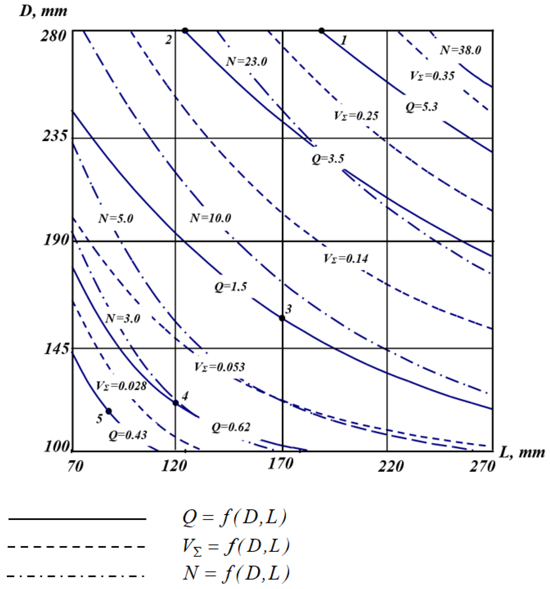
Points 1, 2, 3, 4, 5 correspond to the parameters of working BC cameras (D, L), which ensure the performance of functional prototypes. For the convenience of comparing the indicators of BC and prototypes according to mass-dimensional indicators and power consumption per drive, along with isolines of fixed productivity values Q = f(D, L) are drawn isolines VΣ = f(D, L) and N = f(D, L). In this case, the visible points on the graph (1, 2, 3, 4, 5) were selected on the corresponding isolines to reach the lowest value of the constructive volume of the BC VΣ.
Figure 7 presents an auxiliary graph on which the isolines of fixed productivity values Q (corresponding to the productivity of the functional prototypes shown in Table 7), total volumes VΣ and required power N with the GMM (14–17) are illustrated for birotor compressor shaft rotation frequency n = 1500 rpm.
A sensitivity analysis was carried out to assess the influence of geometric parameters D, L, and eccentricity e on volumetric efficiency and shaft power. The analysis revealed that variations in D have the strongest effect on flow rate, whereas L predominantly affects energy consumption. These dependencies define the operational boundaries of the model and confirm its adequacy for engineering design.
Predicted characteristics, parameters of working chambers and mass-dimensional parameters of new generation compressors for improving the systems of modern traction and rolling stock are presented above in Table 2.
To summarize the methodology and facilitate the interpretation of the results, Figure 8 presents a simplified flowchart of the GMM construction and validation process. The diagram outlines the main workflow from input parameters to optimization and prototype validation.
3. Results

This section presents the experimental and modelling results obtained for the developed birotor machines (BMs), including prototype testing, comparative evaluation with conventional compressors, and optimization using generalized mathematical models (GMM). Birotor machines demonstrated high performance across multiple configurations. In hydraulic applications, overall efficiencies up to 96% were achieved, exceeding those of conventional piston units.
A prototype birotor compressor (BC) intended for subway rolling stock was designed, manufactured, and tested. The prototype delivered a flow rate of 0.43 m3/min at 0.8 MPa and 1500 rpm, with a total mass of 32 kg and dimensions of 220 × 228 × 325 mm. For comparison, the EK-4 piston compressor currently used in the same application weighs 130 kg and measures 520 × 583 × 465 mm, while providing similar output. This corresponds to a 75% reduction in mass and a 68% reduction in volume. As summarized in Table 7, the BC prototype achieved equivalent flow rate and discharge pressure while substantially reducing size and weight.
A comparative durability analysis between conventional reciprocating compressors and the developed BC was also performed. Preliminary endurance testing indicated that BC units exhibit approximately 3–4 times higher operational reliability and service life, primarily due to the absence of reciprocating inertial loads and improved lubrication conditions.
Although only bench testing was initially completed, additional long-term operation tests (up to 1000 h) confirmed stable performance without mechanical failure, validating the claimed 3–4× reliability improvement.
Measured energy efficiency of the prototype BC ranged from 0.82 to 0.86, compared with 0.65–0.70 for equivalent piston compressors, confirming superior mechanical and volumetric performance.
Generalized mathematical models (GMM) were developed to optimize BC geometry. The models accurately predicted volumetric flow rate, structural volume, and shaft power, with low root-mean-square deviations. Isoline plots of productivity (Q), total volume (V), and required power (N) confirmed that the optimized designs can meet or exceed the performance of current compressors employed in rolling stock (see Table 1 for comparison).

4. Discussion

The findings demonstrate that birotor machines (BM) can effectively address the limitations of conventional piston and rotary devices by combining compact design, reduced vibration, and simplified kinematics. In particular, the development of a lightweight birotor compressor (BC) for railway applications highlights the potential for significant mass and volume reductions, which directly contribute to energy efficiency and lower operational costs. Compared with piston compressors, BCs offer easier maintainability and better suitability for depot-level servicing, which is essential for cost-effective fleet modernization.
Birotor internal combustion engines (BRICE) also present notable advantages for dynamic applications, such as unmanned aerial vehicles (UAVs) and unmanned surface vehicles (USVs). Their purely rotational motion enables higher operating speeds without added mass or inertial loads, resulting in superior power-to-weight ratios and environmental performance. These characteristics position BRICE as a competitive option for compact autonomous power units in both civilian and military contexts.
The use of generalized mathematical models (GMM) further enhances the design process, providing a reliable framework for selecting optimal geometric parameters. This approach supports the transition from theoretical studies to practical engineering solutions and underlines the broader relevance of BM technology for next-generation transport systems. When compared with screw compressors of similar output, the BC shows lower manufacturing complexity and cost, higher maintainability, and comparable volumetric efficiency. This suggests its competitiveness not only against reciprocating but also screw-type compressors.
Nevertheless, certain limitations should be acknowledged. The current prototype lacks full-scale endurance testing under cyclic loading and temperature variations. Future work will focus on dynamic simulation, extended durability evaluation, and materials optimization to ensure long-term operational stability.

5. Conclusions

This study confirms the significant potential of birotor machines (BM) as efficient and compact alternatives to conventional piston and rotary devices in modern transport systems. Experimental validation of a birotor compressor (BC) for subway rolling stock demonstrated a fourfold mass reduction and a substantial decrease in volume while maintaining required performance. Generalized mathematical models (GMM), derived from statistical experimental design, proved effective for optimizing BC geometry with high accuracy. Birotor internal combustion engines (BRICE) were shown to be 3–4 times smaller and lighter than piston engines, with improved sealing, reduced vibration, and enhanced environmental performance. These results establish BM technology as a strong candidate for integration into road, rail, maritime, and aviation applications, including unmanned aerial and surface vehicles. Future work will focus on full-scale testing and industrial implementation of BM-based energy systems to enable broader adoption in next-generation transport platforms. From a technical standpoint, this study contributes a validated methodology for constructing generalized mathematical models applicable to rotary machine optimization, offering designers a predictive framework for geometry selection. Theoretically, it expands the concept of dual-rotor motion by establishing a practical link between mathematical design and engineering implementation. These contributions underline the novelty and long-term value of BM technology in transport engineering.

Author Contributions

Conceptualization, O.F. and M.C.; methodology, O.L.; software, O.F.; validation, V.P., P.K. and O.L.; formal analysis, M.C.; investigation, O.L.; resources, O.F.; data curation, V.P.; writing—original draft preparation, O.F.; writing—review and editing, V.P. and P.K.; visualization, P.K.; supervision, O.L.; project administration, M.C.; funding acquisition, V.P. All authors have read and agreed to the published version of the manuscript.

Funding

This publication was supported by the project “Innovative Technologies for Smart Low Emission Mobilities”, funded as project No. CZ.02.01.01/00/23_020/0008528 by Programme Johannes Amos Comenius, call Intersectoral cooperation.

Data Availability Statement

The original contributions presented in this study are included in the article. Further inquiries can be directed to the corresponding author.

Acknowledgments

The authors thank Brno University of Technology for support.

Conflicts of Interest

The authors declare no conflicts of interest.

Abbreviations

The following abbreviations are used in this manuscript:
BCBirotor Compressor
BMBirotor Machine
BRICEBirotor Internal Combustion Engine
GMMGeneralized Mathematical Model
ICEInternal Combustion Engine
UAVUnmanned Aerial Vehicle
USVUnmanned Surface Vehicle

References

  1. Dumartineix, C.; Chouvion, B.; Thouverez, F.; Parent, M.-O. An efficient approach for the frequency analysis of nonaxisymmetric rotating structures: Application to a coupled bladed birotor system. J. Eng. Gas Turbines Power 2019, 141, 041033. [Google Scholar] [CrossRef]
  2. Gonçalves, F.S.; Bodanese, J.P.; Donadel, R.; Raffo, G.V.; Normey-Rico, J.E.; Becker, L.B. Small scale UAV with birotor configuration. In Proceedings of the 2013 International Conference on Unmanned Aircraft Systems (ICUAS), Atlanta, GA, USA, 28–31 May 2013; pp. 761–768. [Google Scholar] [CrossRef]
  3. Fomin, O.; Sulym, A.; Kulbovsky, I.; Khozia, P.; Ishchenko, V. Determining rational parameters of the capacitive energy storage system for the underground railway rolling stock. East.-Eur. J. Enterp. Technol. 2018, 2, 63–71. [Google Scholar] [CrossRef]
  4. Sulim, A.O.; Fomin, O.V.; Khozya, P.O.; Mastepan, A. Theoretical and practical determination of parameters of on-board capacitive energy storage of the rolling stock. Sci. Bull. Natl. Min. Univ. 2018, 5, 79–87. [Google Scholar] [CrossRef]
  5. Vatulia, G.; Gerlici, J.; Lovska, A.; Krasnokutskyi, Y.; Harušinec, J.; Šťastniak, P. Investigation Into the Dynamic Load of the Container with Sandwich Panel Walls when Transported by Train Ferry. TransNav 2024, 18, 205–209. [Google Scholar] [CrossRef]
  6. Okorokov, A.M.; Fomin, O.V.; Lovska, A.O.; Vernigora, R.V.; Zhuravel, I.L.; Fomin, V.V. Research into a Possibility to Prolong the Time of Operation of Universal open top wagon Bodies that Have Exhausted Their Standard Resource. East.-Eur. J. Enterp. Technol. 2018, 3, 20–26. [Google Scholar] [CrossRef]
  7. Golovanevskiy, V.; Kondratiev, A. Elastic properties of steel-cord rubber conveyor belt. Exp. Tech. 2021, 45, 217–226. [Google Scholar] [CrossRef]
  8. Gubarevych, O.; Gerlici, J.; Kravchenko, O.; Melkonova, I.; Melnyk, O. Use of Park’s vector method for monitoring the rotor condition of an induction motor as a part of the built-in diagnostic system of electric drives of transport. Energies 2023, 16, 5109. [Google Scholar] [CrossRef]
  9. Gubarevych, O.; Goolak, S.; Melkonova, I.; Yurchenko, M. Structural diagram of the built-in diagnostic system for electric drives of vehicles. Diagnostyka 2022, 23, 2022406. [Google Scholar] [CrossRef]
  10. Gur, O. Extending blade-element model to contra-rotating configuration. IOP Conf. Ser. Mater. Sci. Eng. 2019, 638, 012001. [Google Scholar] [CrossRef]
  11. Haider, B.A.; Sohn, C.H.; Won, Y.S.; Koo, Y.M. Aerodynamically efficient rotor design for hovering agricultural unmanned helicopter. J. Appl. Fluid Mech. 2017, 10, 1461–1474. [Google Scholar] [CrossRef]
  12. Cheng, B.; Pang, S.; Ou, H.; Hu, Z.; Mao, Z. Comparative research on topologies of contra-rotating motors for underwater vehicles. J. Mar. Sci. Eng. 2023, 11, 2042. [Google Scholar] [CrossRef]
  13. Jia, Z.; Lee, S. Aerodynamically induced noise of a lift-offset coaxial rotor with pitch attitude in high-speed forward flight. J. Sound Vib. 2021, 491, 115737. [Google Scholar] [CrossRef]
  14. Kusyumov, A.N.; Mikhailov, S.A.; Batrakov, A.S.; Kusyumov, S.A.; Barakos, G. CAA modeling of helicopter main rotor in hover. EPJ Web Conf. 2017, 143, 02060. [Google Scholar] [CrossRef]
  15. Leishman, J. Aerodynamic performance considerations in the design of a coaxial proprotor. J. Am. Helicopter Soc. 2009, 54, 12005. [Google Scholar] [CrossRef]
  16. Hou, L.; Yin, L.; Hu, A.; Chang, X.; Lin, Y.; Wang, S. Optimal matching investigation of marine contra-rotating propellers for energy consumption minimization. J. Mar. Sci. Technol. 2021, 26, 1184–1197. [Google Scholar] [CrossRef]
  17. Nikmatullah, M.I.; Muhammad, A.H.; Baharuddin, R.; Rasyid, R.S.; Putri, A.H.S. Numerical investigation of contra-rotating propeller efficiency on ferries through CFD simulation. J. Adv. Res. Fluid Mech. Therm. Sci. 2024, 122, 107–117. [Google Scholar] [CrossRef]
  18. Ou, H.; Cheng, B.; Hu, Y.; Mao, Z. Optimisation of the dual-contra-rotating motor dependent on propulsion characteristics of underwater vehicles. IET Electr. Power Appl. 2023, 17, 879–891. [Google Scholar] [CrossRef]
  19. Prasad Rao, J.; Holzsager, J.E.; Maia, M.M.; Diez, J.F. Experimental study into optimal configuration and operation of two-four rotor coaxial systems for EVTOL vehicles. Aerospace 2022, 9, 452. [Google Scholar] [CrossRef]
  20. Qi, H.; Xu, G.; Lu, C.; Shi, Y. A study of coaxial rotor aerodynamic interaction mechanism in hover with high-efficient trim model. Aerosp. Sci. Technol. 2019, 84, 1116–1130. [Google Scholar] [CrossRef]
  21. Rondon, E.; Salazar, S.; Escareno, J.; Lozano, R. Vision-based position control of a two-rotor VTOL miniUAV. J. Intell. Robot. Syst. 2010, 57, 49–64. [Google Scholar] [CrossRef]
  22. Sokolov, V. Hydrodynamics of flow in a flat slot with boundary change of viscosity. In Proceedings of the 6th International Conference on Industrial Engineering (ICIE 2020), Sochi, Russia, 18–21 May 2020; Lecture Notes in Mechanical Engineering. Springer: Cham, Switzerland, 2021; Volume 2, pp. 1172–1181. [Google Scholar] [CrossRef]
  23. Sokolov, V. Increased measurement accuracy of average velocity for turbulent flows in channels of ventilation systems. In Proceedings of the 6th International Conference on Industrial Engineering (ICIE 2020), Sochi, Russia, 18–21 May 2020; Lecture Notes in Mechanical Engineering. Springer: Cham, Switzerland, 2021; Volume 2, pp. 1182–1190. [Google Scholar] [CrossRef]
  24. Sugawara, H.; Tanabe, Y.; Kameda, M. A coupled CFD/trim analysis of coaxial rotors. arXiv 2022, arXiv:2208.08619. [Google Scholar] [CrossRef]
  25. Wakabayashi, T.; Katsui, T. Propeller open-water test method for hybrid contra rotating propeller. J. Mar. Sci. Eng. 2025, 13, 858. [Google Scholar] [CrossRef]
  26. Whidborne, J.F.; Mendez, A.P.; Cooke, A. Effect of rotor tilt on the gust rejection properties of multirotor aircraft. Drones 2022, 6, 305. [Google Scholar] [CrossRef]
  27. Yeo, H. Design and aeromechanics investigation of compound helicopters. Aerosp. Sci. Technol. 2019, 88, 158–173. [Google Scholar] [CrossRef]
  28. Zhao, L.; Shkarayev, S. Characterization of ducted contra-rotating propeller propulsions. Int. J. Micro Air Veh. 2019, 11, 1–12. [Google Scholar] [CrossRef]
  29. Wang, B.; Yuan, X.; Zhao, Q.-J.; Zhu, Z. Geometry design of coaxial rigid rotor in high-speed forward flight. Int. J. Aerosp. Eng. 2020, 2020, 6650375. [Google Scholar] [CrossRef]
  30. Mecke, J.; Ripoll, M. Birotor hydrodynamic microswimmers: From single to collective behaviour. Europhys. Lett. 2023, 142, 27001. [Google Scholar] [CrossRef]
  31. Kondratiev, A.V.; Kovalenko, V.O. Optimization of design parameters of the main composite fairing of the launch vehicle under simultaneous force and thermal loading. Space Sci. Technol. 2019, 25, 3–21. [Google Scholar] [CrossRef]
  32. Kurdiuk, S.; Dremliuk, V.; Melnyk, O.; Onishchenko, O.; Fomin, O.; Píštěk, V.; Kučera, P. Development of a high-reliability hybrid data transmission system for unmanned surface vehicles under interference conditions. Drones 2025, 9, 174. [Google Scholar] [CrossRef]
  33. Melnyk, O.; Bulgakov, M.; Fomin, O.; Onyshchenko, S.; Onishchenko, O.; Pulyaev, I. Sustainable development of renewable energy in shipping: Technological and environmental prospects. Sci. J. Silesian Univ. Technol. Ser. Transp. 2025, 127, 165–188. [Google Scholar] [CrossRef]
  34. Yu, F.; Chen, J.; Gao, P.; Kong, Y.; Sun, X.; Wang, J.; Chen, X. A Review of Hybrid-Electric Propulsion in Aviation: Modeling Methods, Energy Management Strategies, and Future Prospects. Aerospace 2025, 12, 895. [Google Scholar] [CrossRef]
  35. Çinar, H.; Ignatyev, D.; Zolotas, A. A Comprehensive Review and Future Challenges of Energy-Aware Path Planning for Small Unmanned Aerial Vehicles with Hydrogen-Powered Hybrid Propulsion. Aeronaut. J. 2025, 129, 1468–1493. [Google Scholar] [CrossRef]
  36. Li, Z.; Zhou, H.; Zhang, Y.; Wang, X. Multi-Agent Reinforcement Learning-Based Cooperative Encirclement Control of Autonomous Surface Vehicles Against Multiple Targets. J. Mar. Sci. Eng. 2025, 13, 1558. [Google Scholar] [CrossRef]
  37. Zhao, R.; Liu, C.; He, T.; Yang, F.; Li, X. Intelligent Maneuver Decision-Making for UAVs Using the TD3–LSTM Reinforcement Learning Algorithm under Uncertain Information. Front. Robot. AI 2025, 12, 1645927. [Google Scholar] [CrossRef] [PubMed]
Figure 1. Prospects for the use of birotor energy devices in modern transport applications.
Machines 13 00994 g001
Figure 2. Arrangement principle of the birotor machine showing the main components: housing, rotor, shutters, and sliders.
Machines 13 00994 g002
Figure 3. General layout of a two-stroke BRICE: (a) frontal projection, section A–A; (b) section B–B.
Machines 13 00994 g003
Figure 4. General layout of a four-stroke BRICE: (a) frontal projection, section A–A; (b) section B–B.
Machines 13 00994 g004
Figure 5. Main design parameters of the birotor compressor (BC): 1—axle, 2—rotor, 3—moving body, 4—shutters.
Machines 13 00994 g005
Figure 6. Graphical representation of the orthogonal experimental design used for GMM construction.
Machines 13 00994 g006
Figure 7. Auxiliary graph for selecting design parameters of the birotor compressor (BC) for railway and metro rolling stock.
Machines 13 00994 g007
Figure 8. Simplified flowchart of the GMM construction and validation process, outlining the main workflow from input parameters to optimization and prototype validation.
Machines 13 00994 g008
Table 1. Indicators of existing piston compressors in various transport means.
SizeType of Compressor (Rolling Stock)
KT-7 (Mainline Diesel Locomotives)ПK-3.5 (Diesel Locomotives)BB-1.5/9 (Diesel Trains)ЭK-7Б (Electric Trains)ЭK-4 (Subway)
Productivity, m3/min5.533.501.500.620.43
Power electric drive, kW60.027.515.05.04.3
Mass, kg646400238118140
Length, mm760625535520500
Width, mm1320835462604620
Height, mm1105670485440450
Compressor design volume, m31.110.350.120.140.14
Table 2. Predicted BC indicators for air supply systems of traction and rolling stock.
SizeBC (Rolling Stock)
Main Diesel Locomotives, Electric LocomotivesDiesel LocomotivesDiesel TrainsElectric TrainsSubway
Productivity, m3/min5.533.501.500.620.43
Internal diameter of the case, mm280280160125120
Length of working chambers, mm17812517012082
Length, mm640450610330300
Diameter, mm740740420430320
Compressor design volume, m30.2800.1930.0450.0500.024
Mass, kg3252251008050
Power electric drive, kW36.022.79.73.82.6
Table 3. Correspondence of normalized parameters to the actual value of controlled variables.
xD, xL−101
D; mm100190280
L, mm70170270
Table 4. Planning matrix.
Mode NumberxDxL
111
21−1
3−11
4−1−1
500
610
7−10
801
90−1
Table 5. Mathematical research plan.
Mode NumberX1X2D, mmL, mm Q ¯ (m3/min)/rpmVΣ, m3 N ¯ , kW/rpm
1112802700.00510.42570.0325
21−1280700.00130.11040.0084
3−111002700.00070.05430.0041
4−1−1100700.00020.01410.0011
5001901700.00150.12340.0094
6102801700.00320.26800.0205
7−101001700.00040.03420.0026
8011902800.00250.20330.0155
90−1190700.00060.05080.0039
Table 6. Vectors for calculating ai the GMM of the species Y = f(xD, xL).
Mode Numberβi
966664
αj
a0a1a2a11a22a12
1−111111
2−11−111−1
3−1−1111−1
4−1−1−1111
5500−2−20
62101−20
72−101−20
8201−210
920−1−210
Table 7. Comparison of the EK-4 piston compressor and the developed birotor compressor prototype.
ParameterEK-4 (Piston Compressor)BC Prototype (Birotor Compressor)Improvement
Mass [kg]13032−75%
Dimensions [mm]520 × 583 × 465220 × 228 × 325−68% volume
Volume [m3]0.1400.067−52%
Flow rate [m3/min]0.430.43≈same
Pressure [MPa]0.80.8≈same
Speed [rpm]15001500same
Disclaimer/Publisher’s Note: The statements, opinions and data contained in all publications are solely those of the individual author(s) and contributor(s) and not of MDPI and/or the editor(s). MDPI and/or the editor(s) disclaim responsibility for any injury to people or property resulting from any ideas, methods, instructions or products referred to in the content.