Abstract
The starting torque of Self-lubricating Spherical Plain Bearings (SSPBs) has a significant impact on the reliability and service life of aircraft. Due to the low accuracy of the dynamic detection of the starting torque of the bearing, the starting torque cannot be measured accurately under high-frequency swinging conditions. Therefore, the problem of the dynamic detection accuracy of the starting torque of the bearing on a high-frequency swinging friction and wear tester was proposed to be investigated in this paper, and a dynamic simulation model of the swinging system of the tester was constructed. With the combination of the inertia torque test and the least square method, a mathematical model of the inertia torque was developed and the influence of the inertia torque on the results of the dynamic detection of the starting torque was revealed. At the same time, an error compensation procedure for the on-line dynamic detection of the starting torque was written. This research shows that the inertia torque of the swing system of the tester has a great influence on the detection accuracy of the starting torque. As the swing frequency increases, the inertia torque increases, and the dynamic detection accuracy of the starting torque is reduced. The dynamic detection error of the starting torque of the bearing can be efficiently compensated by the error compensation procedure, and then the detection accuracy can be improved. This research provides a good theory for the design of SSPBs and the reasonable control of the starting torque during the use of the bearings, and it is valuable for engineering practice.
1. Introduction
The starting torque of Self-lubricating Spherical Plain Bearings (hereinafter referred to as SSPBs) has a significant impact on the operational security and service life of aircraft [1,2,3]. The accurate detection of the starting torque is considered to be one of the important prerequisites for evaluating the overall performance of aircraft and other equipment [4,5]. Therefore, it is necessary to investigate the detection accuracy of the starting torque during the reciprocating swing motion.
The starting torque is the friction torque generated between the bearing and the liner when the inner ring and outer ring transition from a stationary state to relative rotation. The detection method of the starting torque of the SSPBs is shown in Figure 1; the outer ring of the bearing is fixed and the inner ring is rotated around its central axis, and then the starting torque detection of the bearing is realized. In order to make the starting torque detection more accurate, the inner ring should be rotated 2–3 turns before the starting torque detection. In addition, when fixing the outer ring, it should be ensured that the deformation of the outer ring is as small as possible (that is, the deformation of the outer ring of the bearing is minimized as much as possible so that the squeezing effect on the liner inside the bearing is reduced and the influence on the detection accuracy of the starting torque of the bearing is reduced) and the starting torque generated when the inner ring begins to rotate is recorded [6,7,8,9].
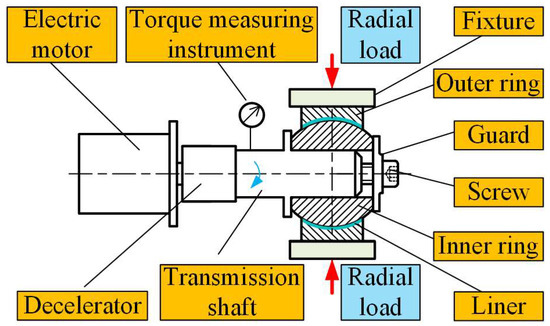
Figure 1.
Schematic diagram of the starting torque detection.
The different detection standards for the starting torque of SSPBs result in various errors in the detection results. In order to improve the detection accuracy of the starting torque, the detection methods and requirements specified in the existing standards have been analyzed by many experts and scholars. Comparative tests of the no-load starting torque of the same type SSPBs at home and abroad in a hygrothermal environment were conducted by Lin et al.; the influence mechanism of the hygrothermal environment on the no-load starting torque of bearings and the reasons for differences were analyzed [10]. In order to address the issue of significant variations in the detection results of the no-load starting torque of SSPBs, the detection methods of no-load starting torque were compared by Zhang et al., and the influence of the detection environment on the results was investigated, and then a multi-point detection method was proposed based on the detection uniformity of the no-load starting torque [11]. The structure and the manufacturing technology of the SSPBs were analyzed, and according to the domestic and international standards on the no-load starting torque detection of SSPBs, the effect of self-lubricating materials, clamping methods, detection points, and the environment on the detection accuracy of the no-load starting torque was studied by Zheng [12].
One of the prerequisites for analyzing the starting torque of SSPBs is research on the detection accuracy of the starting torque. The finite element method was adopted by Li, and the influence of various clamping methods on the detection accuracy of the no-load starting torque of the bearings was quantitatively analyzed [13], and the results verified that the axial end face clamping method was superior to the radial clamping method. By means of numerical integration, the relationships between the axial load, radial load, and starting torque of the bearings were derived [14], and it was found that in order to ensure the detection accuracy, additional axial load should be avoided as much as possible during the starting torque detection. The influence of the ambient temperature and humidity on the starting torque of SSPBs was investigated by Lu and Su [15] through starting torque detection tests, and the results showed that the environment humidity has a greater influence on the no-load starting torque.
In summary, the detection methods and environments of the starting torque of SSPBs have been researched by experts and scholars at home and abroad. The starting torque of an SSPB is one of the essential inspection items after its manufacture and installation; these research results have important implications for the theoretical research and the engineering application of starting torque detection. However, due to the influence of many factors on the starting torque of the bearings [3,8,16,17], the detection accuracy of the starting torque under high-frequency swing conditions is reduced. Up to now, there have been few reported studies on data analysis and error analysis of the starting torque detection of SSPBs, and the working performances of SSPBs cannot be accurately evaluated.
In this paper, in order to increase the operation reliability of the SSPBs (the flowchart diagram of this paper is shown in Figure 2), the dynamic detection of the starting torque of the SSPBs was carried out by a high-frequency swing friction and wear tester. A dynamic simulation model of the swing system of the tester was established, and the influence of the inertia torque of the swing system on the dynamic detection error of the starting torque was investigated, and an error compensation program for the dynamic detection was written so that the detection error can be compensated and the detection accuracy can be improved. It is of great significance to conduct further research on the theoretical and engineering applications of the starting torque detection of SSPBs.
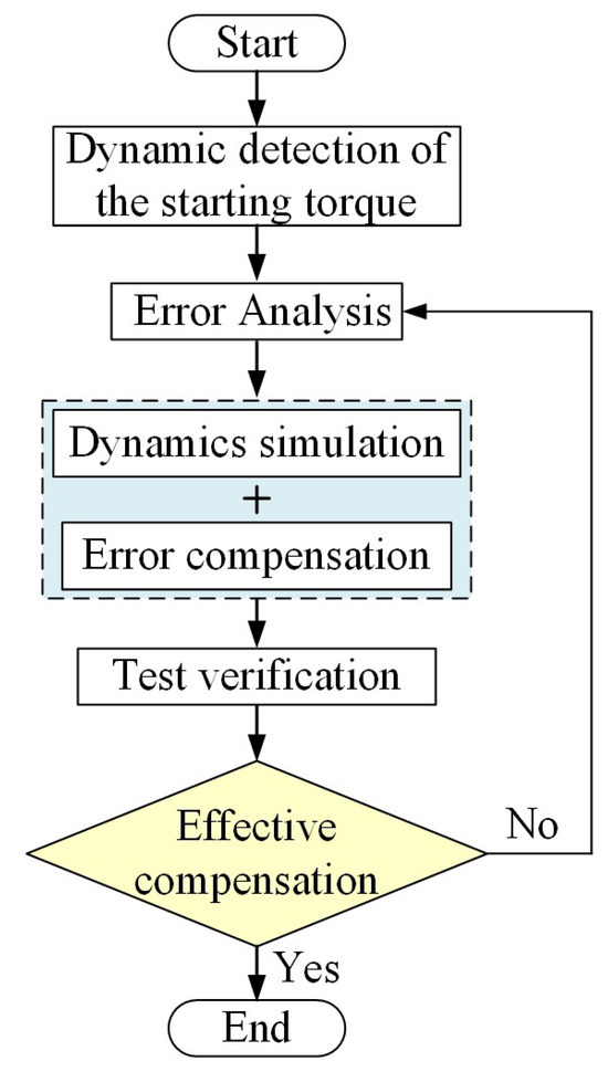
Figure 2.
Flowchart diagram of this paper.
2. Experimental Apparatus and Dynamic Detection of the Starting Torque
2.1. Experimental Apparatus
The dynamic detection of the starting torque of the SSPBs was carried out in the laboratory on a high-frequency swing friction and wear tester for the SSPBs. The tester mainly includes a swing system, loading system, fixture system, control system, and so on, and the overall layout of the tester is shown in Figure 3a. Its loading force range is 0–3000 N, with a maximum swing frequency of 35 Hz and a maximum swing angle of 5°, and the detection accuracy of the starting torque is 0.5% FS. The radial loading of the bearing can be realized by the tester, and its motion form can be controlled. At the same time, the friction torque of the bearing, the temperature, and the change in the wear amount of the friction surface can be monitored in real time during the bearing swing.
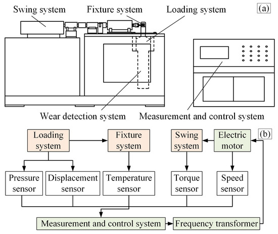
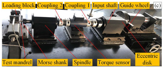
Figure 3.
The tester for torque detection of the SSPBs: (a) the overall layout of the tester; (b) system composition diagram of the bearing tester; and (c) the main structure of the swing system of the tester.
The schematic diagram of the working system composition of the tester is shown in Figure 3b. The loading system provides the load for the starting torque detection tests. When the load reaches the test load, it maintains the load at a constant level. The fixture system ensures effective clamping of the bearing, and the swing system provides a reciprocating swing motion for the bearing test. The swing system is connected to the electric motor via a key to transmit power, and the reciprocating swing motion is achieved through a crank–rocker mechanism. The measurement and control system utilizes a PC as its core and is integrated with specialized data acquisition equipment, which enables the collection and processing of data such as oscillation frequency, applied load, and friction torque. Simultaneously, various test data can be collected, stored, and displayed in real time.
The main structure of the swing system of the tester is shown in Figure 3c. The swing system has a swing angle of ±4°, and it mainly consists of an eccentric disk, guide bar, input shaft, coupling, torque sensor, spindle, guide wheel, morse shank, loading block, and test mandrel [2]. The inner ring of the bearing is assembled to the test mandrel via an interference fit, and the outer ring is clamped by the loading block. During the test, the test mandrel performs reciprocating oscillatory motion, and then the inner ring of the bearing is driven to swing.
2.2. Dynamic Detection of the Starting Torque
A radial load of 1000 N was applied to the SSPB and kept constant. In the actual working conditions, the reciprocating swing around its center axis is the main motion form of the SSPBs. Therefore, the swing frequencies of 1 Hz, 10 Hz, and 20 Hz were selected for the dynamic detection of the starting torque of the bearings. In order to reduce the influence of the random errors on the test results, a method was employed where detection tests were conducted and the coarse error values were eliminated, and then the torques corresponding to different frequencies were averaged to obtain the torque values measured by the test. The results are shown in Table 1.

Table 1.
Starting torque at different swing frequencies.
As can be seen from Table 1, the starting torque shows an increasing trend as the swing frequency increases, the starting torque increases more and more significantly with the increase in the swing frequency, and the error between the maximum and minimum of the starting torque is up to 3.43 N∙m. The variation in the detection results of the starting torque is not solely attributable to the special physical properties of the liner. Since the bellows coupling selected for the transmission mechanism of the tester is a flexible coupling, the assembly error caused by shaft alignment is not considered. In order to realize the precise detection of the starting torque of the bearing, the torque sensor is in series with the swing system. The reason for this phenomenon may be that during the swinging motion of the spindle system, an inertia torque is generated by the components located behind the torque sensor, and the torque measured in the tester represents the sum of the starting torque and the inertia torque. Therefore, it is necessary to study the effect of the inertia torque on the results of the detection.
3. Dynamics Simulation of the Swing System
3.1. Simulation Model
In order to study the kinematic laws of the swing system (the main structure of the swing system is shown in Figure 3c) of the tester at different swing frequencies and their influence on the dynamic detection of the starting torque of the bearing, the actual working conditions of the swing system of the tester for the multi-rigid body dynamics were modeled by Adams software in this paper.
The MS14101-9 type of SSPBs was selected as the research object in this paper. In actual working conditions, the different swing frequencies and loads are applied to the SSPBs. In order to save simulation time, the load could be set to a constant. This paper mainly aims at the modeling of the moving components in the swing system of the tester. Due to the complex structure of the torque sensor and to simplify the simulation model, the torque sensor was reduced to an optical axis with its inertia torque equal to that of the torque sensor. At the same time, the unnecessary structures such as chamfers and threads on the swing components were deleted to ensure the accuracy of the numerical simulation and shorten the simulation time.
The three-dimensional schematic diagram of the main structure of the tester is shown in Figure 4a. The loading block consists of an upper and lower section. In order to more clearly illustrate the experimental principle, only one loading block was provided in this paper. In order to reduce the difficulty of the analysis and take into account the variation in the starting torque of the main study object (bearing) under radial load, the bearing was set as a flexible body. The other parts of the swing system with the same material properties and no relative motion were set as a rigid body by a Boolean operation, and thus the rigid–flexible coupled dynamics analysis of the swing system was realized. The simulation model of the swing system is shown in Figure 4b.
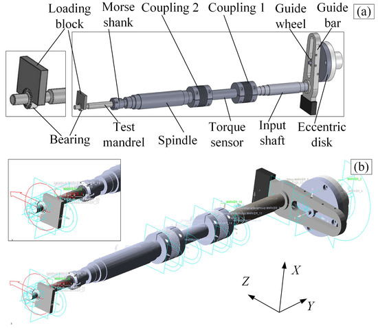
Figure 4.
The swing system of the tester: (a) the three-dimensional schematic diagram of the main structure of the swing system of the tester; (b) simplified simulation model of the swing system.
According to the connection relationships between the components of the swing system and its motion principle, the eccentric disk and the earth, and the guide rod and the eccentric disk were set up as rotational pairs, respectively. The constraint between the guide wheel and the guide bar was set up as a sliding pair. The input shaft was set up as a fixed pair with the guide rod, and coupling 1 was set up as a fixed pair between the input shaft and the torque sensor. The Coupling 2 was provided with a fixed pair constraint between the main shaft and the torque sensor, respectively.. The test mandrel was provided with a fixed pair between the main shaft and the inner ring of the bearing. A cylindrical pair was set between the earth and the input axis, and a sliding pair was set between the loading block and the earth. A ball–hinge pair was set between the inner ring and the outer ring, and a fixed pair was set between the outer ring and the earth.
Under the high-frequency and light-load simulation conditions, the friction coefficient between the inner ring and the liner was set to 0.07. The friction coefficient between the guide bar and the guide wheel was set to 0.1. The swing time was set to 1 s, the radial load was set to 1000 N, and the swing angle was set to ±4°. Simultaneously, the spindle was set to perform a reciprocating swinging motion at a frequency ranging from 1 Hz to 35 Hz, and a numerical simulation was conducted to detect the starting torque of the bearings.
3.2. The Analysis of Simulation Results
The dynamic simulation model is solved according to the simulation time, the step number, and the solvers. The angular velocity and angular acceleration of the spindle, the torque on the shaft of the torque sensor, and the starting torque of the bearing were detected at different swing frequencies. The influence of the inertia torque generated by the change in the swing frequency on the dynamic detection results of the starting torque was investigated.
The solver within the own system of the Adams 2012 software was employed to solve the simulation results of the swing system, yielding the curves shown in Figure 5. The variation curves of the detection values of the torque sensor and the starting torque are shown in Figure 5a. When the swinging mechanism of the swing system swings back and forth between the two limit positions, the movement of the mechanism is accelerated and then decelerated. Due to the existence of the inertia torque, the detection values of the torque sensor are greater than those for the starting torque during the acceleration of the swing system. However, during the deceleration of the swing system, the detected values of the torque sensor are less than those for the starting torque.
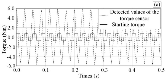
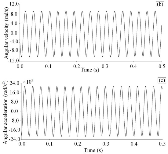
Figure 5.
The dynamic simulation results of the spindle of the swing system: (a) curves of the starting torque and the torque measured by the torque sensor with detection time; (b) angular velocity of the spindle of the swing system; and (c) angular acceleration of the spindle of the swing system.
As can be seen in Figure 5a, the maximum value of the starting torque of the bearing is 0.7262 N∙m, which is close to the starting torque measured in the test in Table 1, and this shows that the simulation model has a certain accuracy. However, the maximum torque of 5.7268 N∙m measured by the torque sensor is due to the fact that the torque detected by the torque sensor includes not only the starting torque of the bearing, but also the inertia torque generated by the swing system. The large difference between the two values can be seen intuitively, and thus the inertia torque has a large impact on the detection accuracy of the starting torque. Therefore, the impact of the inertia torque on the dynamic detection accuracy of the starting torque of the bearing should be taken into account.
As shown in Figure 5b,c, the angular velocity and angular acceleration curves of the spindle of the swing system are obtained by setting the same parameters as in Figure 5a. It can be seen that the maximum angular velocity of the spindle is equal to 9.3578 rad/s and the maximum angular acceleration is equal to 2170.5367 rad/s2.
The numerical simulations were conducted by altering only the swing frequency of the tester; the relationship curves of the starting torque of the bearing, the starting torques measured by the torque sensor, and the inertia torque for different swing frequencies were obtained, as shown in Figure 6a. It can be seen that the detection accuracy of the starting torque is less affected by the inertia torque at low frequencies, but when the swing frequency increases, the effect of the inertia torque on the detection accuracy becomes larger and the inertia torque increases. The curves of the swing frequency and the angular acceleration are shown in Figure 6b. As can be seen from Figure 6b, with the increase in the swinging frequency of the swing system, the swing angular acceleration also increases, and when the swing frequency exceeds 10 Hz, the swing angular acceleration increases more obviously. Meanwhile, according to the concept of inertia torque, the inertia torque will increase with the increase in the swing angular acceleration. It can be seen from Figure 6a that when the swing frequency of the swing system is 35 Hz, the starting torque measured by the torque sensor is almost the same as the inertia torque. Therefore, the influence of the inertia torque on the starting torque should be taken into full consideration during the test.
Figure 6.
The relation curves of the swing frequency with the torque and the angular acceleration: (a) relation curve of the swing frequency and the torque; (b) relation curve of the swing frequency and the angular acceleration.
4. Dynamic Detection Error Compensation
4.1. Modeling of the Inertia Torque
The tester shown in Figure 3 was still employed, and to avoid the influence of other factors, the one-factor method was adopted to the test the inertia torque of the swing system. The radial load applied to the bearing was zero and remained constant. The inertia torque was measured by the torque sensor with the swing frequency increasing in a gradient from 1 Hz to 35 Hz. The data processing method described above for the dynamic detection of the starting torque was employed and the inertia torque of the swing system was measured, as shown in Table 2.
Table 2.
Inertia torque at different swing frequencies.
As can be seen from Table 2, during the detection test, the inertia torque shows an increasing trend as the swing frequency increases. The different inertia torques are caused by the different swing frequencies, which directly affects the detection accuracy of the torque sensor.
Due to the inertia of the swing system of the tester at high swing frequencies, the inertia torque of the swing system varies with the swing frequency of the parts behind the torque sensor during the acceleration or deceleration of the swing process. The inaccuracy of the starting torque detection is directly caused by the presence of the inertia torque. Therefore, the elimination or reduction in accuracy of the dynamic detection of the starting torque of the bearing by the influence of the inertia torque is a key issue that needs to be solved.
Based on the above analysis, in order to ensure that the influence of the inertia torque on the detection results of the starting torque can be accurately investigated, the least squares method was employed to process the inertia torque measured by the tester at different swing frequencies in Table 2 [18,19,20]. The fitted curve between the inertia torque and the swing frequency of the swing system was obtained by Matlab 2014 software (as shown in Figure 7), and the relative error between the two is 1.53%.
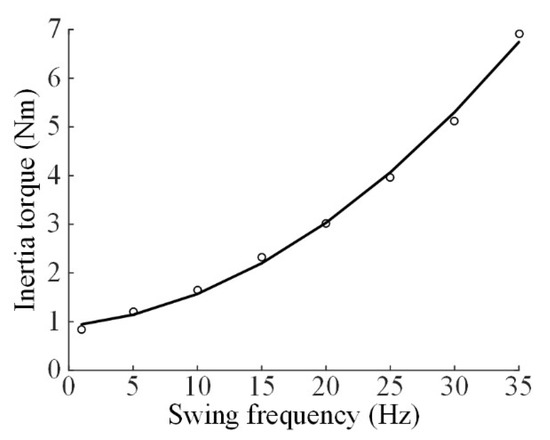
Figure 7.
Fitting curve between the inertia torque and the swing frequency.
The inertia torque of the swing system in the tester shown in Figure 3 is a consequence of the interaction between its angular acceleration and rotational inertia. The reciprocating swing motion was achieved through a crank–rocker mechanism. During this process, the primary components generating inertia torque detectable by the torque sensor include the torque sensor shaft, morse shank, test mandrel, coupling, and spindle. Since the structures and dimensions of these components were fixed, which means their mass was constant, the effect of mass variation was not considered during error compensation. Therefore, the impact of the mass variation was not considered when modeling the inertia torque. Additionally, the angular acceleration of the oscillating system was determined by the transmission structure. Since the structural size of the crank–rocker mechanism in the tester used in this paper was fixed, it could be concluded that variations in the angular acceleration of the swing system were caused by changes in the swing frequency. In Section 3 of this paper, the relationship between the swing frequency and the angular acceleration was analyzed during the dynamic analysis of the swing system. Therefore, the swing frequency was selected as the variable to investigate its effect on the inertia torque, which may include the influence of the angular acceleration on the inertia torque.
In Figure 6, the equation for the inertia torque Tg versus the swing frequency f of the swing system is obtained, as shown in Equation (1):
where f—the swing frequency of the swing system (Hz).
4.2. The Modeling and Strategy for the Error Compensation
The principle of the error compensation for the dynamic detection of the starting torque of the bearing is that the inertia torque is subtracted from the torque captured by the torque sensor, and thus the accuracy of the torque detection can be improved. Therefore, combining with Equation (2), the dynamic starting torque after the error compensation can be obtained as follows:
where
- Td—dynamic starting torque of the bearing (N∙m);
- Tc—torque measured by the torque sensor (N∙m).
5. Test
5.1. Detection System of the Tester
In this paper, in order to improve the accuracy of the dynamic detection of the starting torque of the bearing, the error compensation program for the dynamic detection of the starting torque is mainly written in the Labview software. Based on the error compensation principle, an error compensation system for the dynamic detection of the starting torque of the SSPBs has been designed. According to the needs of the torque detection, the front panel of the compensation system consists of a swing frequency input module, an error compensation value of the torque display module, a torque display module, and a display window for the curve of the torque. The signal of the starting torque obtained by the data acquisition system is a periodic signal, and the front panel of the system is shown in Figure 8a, and the maximum value of the signal in each cycle is obtained by means of the error compensation system. The error value is subtracted from the maximum value of the starting torque and a more accurate value can be obtained. The various starting torques can be plotted as a curve and displayed on the front panel of the system, and the trend of torque variation can be obtained. The error compensation program is shown in Figure 8b.
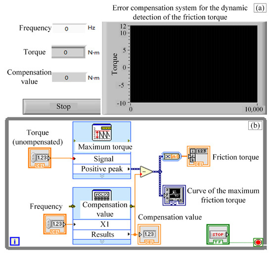
Figure 8.
Error compensation system for dynamic detection of starting torque: (a) the front panel of the compensation system; (b) the error compensation program for the dynamic detection.
Before using the error compensation system of the starting torque, the swing frequency of the swing system of the tester should be determined, and then the swing frequency can be entered on the front panel. When the tester is started, Labview 2012 softwareis run, and then the torque is displayed by the torque display module, which is the starting torque after error compensation. At the same time, the variation curve of the starting torque is presented in the curve display window.
5.2. Dynamic Detection of the Starting Torque After Error Compensation
In order to verify the accuracy of the error compensation system for dynamic detection of the starting torque of the bearing, the uncompensated starting torque signals at the different swing frequencies are simulated based on sinusoidal signals at the different swing frequencies. The maximum swing frequency of the swing system is 35 Hz; therefore, the swing frequency is selected to increase gradually in a gradient from 1 to 35 Hz. The bearings were subjected to a radial load of 1000 N with different swing frequencies, and the starting torque was observed. The results of the error compensation of the starting torque obtained from the test are shown in Figure 9.
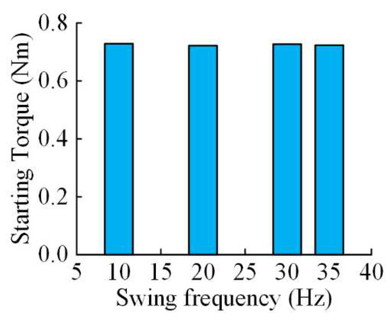
Figure 9.
The results of the error compensation of the starting torque.
The starting torques of the bearing of 0.7288 N∙m and 0.7233 N∙m were detected at the swing frequencies of 10 Hz and 35 Hz, respectively. It can also be seen from the results that the starting torque is almost the same at 10 Hz and 35 Hz. The above analysis shows that the compensation of the starting torque can be realized by this system regardless of the high or low swing frequency, and its detection accuracy is effectively improved.
6. Conclusions
In this paper, the problem of the dynamic detection accuracy of the starting torque of SSPBs was investigated, an error compensation program for its dynamic detection was written, and the following conclusions were obtained:
- (1)
- During the dynamic detection of the starting torque of the SSPBs, the torque detected by the torque sensor not only includes the starting torque of the bearing, but also the inertia torque of the swing system. As the swing frequency of the swing system increases, the inertia torque increases, and the dynamic detection accuracy of the starting torque of the bearing is reduced.
- (2)
- The relative error between the test values and the simulation values of the starting torque of the bearing is 17.5%, which indicates that its change tendency can be intuitively reflected by the established dynamic simulation model. The relative error between the test values and the theoretical values of the inertia torque is 1.53%, which indicates that the relationship between the two can be accurately reflected by the established mathematical model between the inertia torque and the swing frequency.
- (3)
- The relative error of the dynamic detection of the starting torque of the bearing is 0.75% at the swing frequencies of 10 Hz and 35 Hz, respectively. The dynamic detection error can be effectively compensated by the error compensation program, and the dynamic detection accuracy of the starting torque can be improved.
Author Contributions
Conceptualization, Q.W.; data curation, Q.W. and R.G.; funding acquisition R.G., Q.W., B.G., L.Y., and R.X.; methodology, Q.W.; project administration, F.L.; software, Z.Z. and R.X.; supervision, R.G.; validation, F.L.; visualization, Z.Z.; writing—original draft, Q.W.; writing—review and editing, Q.W., F.L., and L.Y. All authors have read and agreed to the published version of the manuscript.
Funding
This study is supported by the Key R&D Special Project of Henan Province (231111221000) and Henan Provincial Science and Technology Research Project (No. 232102230061, 232102210167, 242102220116, 252102221033) and the Natural Science Foundation of Henan Province (252300421327) in China.
Data Availability Statement
All data generated or analyzed during this study are included in this published article.
Conflicts of Interest
The authors declare no conflicts of interest.
References
- Zhang, Q.; Hu, Z.; Su, W.; Zhou, H.; Qi, X.; Yang, Y. Investigation on Housing Chamfer Parameters in Roller Swaging for Self-lubricating Spherical Plain Bearings Assembly. Int. J. Adv. Manuf. Technol. 2018, 95, 1087–1099. [Google Scholar] [CrossRef]
- Li, W.; Hu, Z.-Q.; Yang, Y.-L.; Fan, B.-L.; Zhou, H.-L. Modeling and Verification of Comprehensive Errors of Real-time Wear-depth Detecting for Spherical Plain Bearing Tester. J. Cent. South Univ. 2017, 24, 533–545. [Google Scholar] [CrossRef]
- Bashandeh, K.; Lan, P.; Meyer, J.L.; Polycarpou, A.A. Tribological Performance of Graphene and PTFE Solid Lubricants for Polymer Coatings at Elevated Temperatures. Tribol. Lett. 2019, 67, 99. [Google Scholar] [CrossRef]
- Qiu, M.; Tian, K.; Zhang, Y. Effect of Ambient Temperature on the Formation Mechanism of PTFE Liner Transfer Film of Spherical Plain Bearings. Mech. Ind. 2021, 22, 11. [Google Scholar] [CrossRef]
- Wang, Q.; Chen, J.; Liu, C.; Zhao, J.; Zheng, X.; Hu, Z. Research on Loading Parameters of Roller Swaging Process of Self-lubricating Spherical Plain Bearings. Int. J. Adv. Manuf. Technol. 2021, 118, 3737–3747. [Google Scholar] [CrossRef]
- Wang, Q.; Chen, J.; Zhou, H.; Lyu, X.; Hu, Z. Research on the mathematical modelling of the starting torque of self-lubricating spherical plain bearings. Proc. Inst. Mech. Eng. Part C J. Mech. Eng. Sci. 2022, 236, 4049–4058. [Google Scholar] [CrossRef]
- Yang, M.; Zhang, Z.; Wu, L.; Li, P.; Jiang, W.; Men, X. Enhancing Interfacial and Tribological Properties of Self-lubricating Liner Composites via Layer-by-Layer Self-assembly MgAl-LDH/PAMPA Multilayers Film on Fibers Surface. Tribol. Int. 2019, 140, 105887. [Google Scholar] [CrossRef]
- Aguirrebeitia, J.; Abasolo, M.; Vallejo, J.; Coria, I.; Heras, I. Methodology for the Assessment of Equivalent Load for Self-lubricating Radial Spherical Plain Bearings under Combined Load. Tribol. Int. 2017, 105, 69–76. [Google Scholar] [CrossRef]
- Gong, L.; Yang, X.; Kong, K.; Zhong, S. Optimal Design for Outer Rings of Self-lubricating Spherical Plain Bearings Based on Virtual Orthogonal Experiments. Adv. Mech. Eng. 2018, 10, 1687814018783402. [Google Scholar] [CrossRef]
- Lin, J.; Zhang, L.; Li, Y.W.; Zhao, Y.C.; Jiao, Z.Q. Effects of damp heat on no-loadrotational starting torque of self-lubricating spherical bearings. Bearing 2013, 8, 30–32. (In Chinese) [Google Scholar]
- Zhang, L.; Zhao, Y.; Lin, J.; Zhang, Y.; Li, Y.; Chang, Z. Analysis on Measurement Standard for No-Load Rotational Starting Torque of Self-lubricating Spherical Plain Bearing. Lubr. Eng. 2015, 40, 112–115. (In Chinese) [Google Scholar]
- Zheng, M. Research on the No-Load Rotational Starting Torque of Self-lubricating Spherical Plain Bearings. Intern. Combust. Engine Parts 2018, 24, 73–74. (In Chinese) [Google Scholar]
- Li, B.; Liu, L.; Zhang, T.; Liu, H. Analysis on Measurement Method for Starting Torque of Self-Lubrication Spherical Plain Bearing Without Load. Bearing 2013, 3, 57–60. (In Chinese) [Google Scholar]
- Cong, Z.; Li, B.; Li, R. Measuring Method for Swinging Friction Torque of Self-Lubricating Joint Bearing. Metrol. Meas. Tech. 2016, 43, 43–46, 48. (In Chinese) [Google Scholar]
- Lu, C.; Su, W. Study on Influence of Temperature and Humidity on Starting Torque and Clearance of Self-lubricating Spherical Plain Bearing. Aviat. Precis. Manuf. Technol. 2021, 57, 11–13, 15. (In Chinese) [Google Scholar]
- Zhang, Q.; Hu, Z.; Yang, Y.; Ma, J.; Qi, X. Investigation of the Roller Swaging Process for Self-lubricating Spherical Plain Bearings Assembly. J. Mater. Process. Technol. 2017, 241, 36–45. [Google Scholar] [CrossRef]
- Qiu, M.; Yang, Z.; Lu, J.; Li, Y.; Zhou, D. Influence of Step Load on Tribological Properties of Self-lubricating Radial Spherical Plain Bearings with PTFE Fabric Liner. Tribol. Int. 2017, 113, 344–353. [Google Scholar] [CrossRef]
- Huang, R.; Su, R.; Qi, W.; He, Z. Understanding the key factors for enzymatic conversion of pretreated lignocellulose by partial least square analysis. Biotechnol. Prog. 2010, 26, 384–392. [Google Scholar] [CrossRef] [PubMed]
- Ghasemi, S.E.; Hatami, M.; Ahangar, G.R.M.; Ganji, D.D. Electrohydrodynamic flow analysis in a circular cylindrical conduit using Least Square Method. J. Electrost. 2014, 72, 47–52. [Google Scholar] [CrossRef]
- Zheng, Y.; Wang, S.; Feng, J.; Tse, C.K. A modified quantized kernel least mean square algorithm for prediction of chaotic time series. Digit. Signal Process. 2016, 48, 130–136. [Google Scholar] [CrossRef]


Disclaimer/Publisher’s Note: The statements, opinions and data contained in all publications are solely those of the individual author(s) and contributor(s) and not of MDPI and/or the editor(s). MDPI and/or the editor(s) disclaim responsibility for any injury to people or property resulting from any ideas, methods, instructions or products referred to in the content. |
© 2025 by the authors. Licensee MDPI, Basel, Switzerland. This article is an open access article distributed under the terms and conditions of the Creative Commons Attribution (CC BY) license (https://creativecommons.org/licenses/by/4.0/).