Abstract
Inconel 718 is a Ni-based superalloy with excellent corrosion resistance, heat resistance, high-temperature strength and high creep resistance. It is also known to be a difficult-to-machine material. Conventional machining methods have not only low machining efficiency, but also high cost and low versatility using CBN and ceramic tools, so cost reduction and highly efficient machining by substituting relatively inexpensive cemented carbide tools are required. Some results on the tool life in milling for intermittent cutting for Inconel 718 superalloy have been reported, and the tool life has been considered a problem. Therefore, there is a need to clarify the basic characteristics of milling, such as tool wear and adhesion conditions, and to identify long tool life and highly efficient cutting conditions in order to achieve highly efficient milling of Inconel 718 superalloy. In this study, the milling of Inconel 718 superalloy was conducted using an end mill with a constant depth of cut, and milling efficiency was defined as the table feed rate of the milling machine in mm/min. The tool wear, welding condition, and surface roughness of the workpiece were evaluated according to the combination of cutting speed and feed rate per edge, with a milling efficiency of 800 mm/min. The experimental results showed that with the combination of a cutting speed of 10.33 m/min and feed rate of 0.4 mm/tooth, and the combination of 20.65 m/min and 0.4 mm/tooth, when there was a lower cutting speed and higher feed rate per edge, less weld detachment occurred, less progression of flank wear, and less chipping occurred, and the tool edge was more stable. It was also confirmed that, by keeping the cutting speed constant and increasing the feed rate per edge, both long tool life and highly efficient milling were possible under the above conditions.
1. Introduction
There has been an increasing demand for highly efficient, high-quality machining of high-performance materials in cutting operations in recent years. Inconel 718 is a nickel-based heat-resistant superalloy with excellent heat and corrosion resistance, making it a highly functional and excellent material. It is currently used as a material in high-temperature, high-load environments, such as in turbine parts for aircraft jet engines [1,2,3]. Its high strength at high temperatures and resistance to acids and bases are significantly superior to other materials, and it can be expected to be applied to a wide range of products in line with recent demand. However, it is classified as a difficult-to-machine material due to properties such as easy work hardening, high chemical affinity with tools and low thermal conductivity. One indicator of machinability is the machinability index [4].
The machinability index is a quantity indicating the workpiece’s difficulty in cutting, with free-cutting brass steel at 100. Stainless steel is 50–40, titanium is 30–20 and Inconel is 15–6, which is considered to be troublesome among difficult-to-machine materials due to its low machinability index [5,6]. Therefore, it has problems such as short tool life, welding, rapid temperature rise and unstable cutting conditions, making it extremely difficult to achieve high efficiency and high quality. For Inconel 718 superalloy, attempts have been made by many researchers to increase machining efficiency by increasing the cutting speed [7]. However, low cutting speeds are recommended for machining Inconel 718 superalloy because the tool surface temperature increases and the tool life is shortened. So far, cutting speeds have been reduced, feeds have been reduced, WET machining has been carried out using cutting oils with high cooling performance, and tools with excellent heat resistance and wear resistance, such as CBN and ceramic tools, have been used [8]. However, in previous studies, the high cost and low versatility of CBN and ceramic tools have led to problems as well as a reduction in machining efficiency.
Developments in tool technology have expanded the range of machining with cemented carbide tools [9,10,11]. Carbide tools are inexpensive, versatile and are currently used to machine more and more materials. By using cemented carbide tools with coatings with excellent heat and wear resistance, it is expected that Inconel 718 superalloy can be machined with high efficiency and precision [12]. In addition, tools capable of machining at higher cutting speeds and feed rates by changing the tool geometry are now being manufactured.
There are two methods for increasing machining efficiency: one is to machine both with the cutting speed and feed rate at a high speed, and the other is to machine with one with the cutting speed and feed rate at a low speed while the other is at a high speed. Most of these studies have been on the latter case, and in recent years, a machining method has been proposed in which the cutting speed is significantly increased and the temperature of Inconel 718 superalloy is raised to the softening temperature, but the machines and tools used are limited [13]. Furthermore, wear mechanisms and surface integrity of coated tools in Inconel 718 superalloy have been investigated [14,15,16,17], and cooling and lubricating strategies in Inconel alloy have been reviewed [18].
One of the reasons for the difficulties in the cutting of Inconel 718 superalloy is its high chemical affinity. The workpiece material is therefore welded to the tool edge, forming a built-up edge. The built-up edge is a part of the work material that breaks off, is accumulated around the tool edge and is machined as part of the tool edge [19]. Elucidation of welding is essential for extending tool life and realizing highly efficient machining, and the study on the use of the built-up edge for machining in various work materials is currently being conducted [20,21].
Difficulties associated can be deduced that surface reliability, tool wear and durability of the cutting tool during the operation are of prime importance; however, the assessment of interaction between tool wear and surface reliability of Inconel 718 superalloy still needs to be explored.
Based on the above background, milling of Inconel 718 superalloy is conducted, and the cutting conditions that improve milling efficiency use a coated carbide end mill under several cutting speeds and feed rates in this study. The objective of this study is to clarify the effects of cutting speed and feed rate on tool chipping, tool wear, surface roughness of the workpiece, coating damage, and welding. Based on the obtained result, a combination of cutting speed and feed rate is optimized. This enables the identification of cutting parameters with a significant influence. Thus, this study involving milling will lead to improvement of milling efficiency, especially when considering Inconel 718 superalloy and difficult-to-machine materials. This result will be able to apply to the complex shape structure of Inconel 718 superalloy, such as aircraft turbine blades and gas turbines.
2. Experimental Method
2.1. Machine Used and Experimental Method
As shown in Figure 1, an NC (Numerical Control) milling machine (FMB-400, Okuma & Howa Machinery Ltd., Kohnan, Japan) with a maximum spindle speed of 4000 rpm was used in experimental milling, and Inconel 718 superalloy was fixed to a vise on the table of the NC milling machine with a solid carbide end mill [22]. Several cutting speeds and feed rates in milling, and tool observations were made on the rake face and flank face. The tool life is defined as the occurrence of chipping on the tool based on experiences in this study [23], and the experimental milling is terminated when one of the following conditions occurs: (1) tool life is reached, (2) the maximum tool wear exceeds 0.1 mm or (3) the cutting length reaches 10 m. The tool life, tool wear, coating damage, amount of welding and surface roughness are mainly evaluated in this study. The used cutting fluid was Surecut CA-15 (Yanase SEIYU Co., Ltd., Osaka, Japan). Table 1 shows the cutting oil specifications.
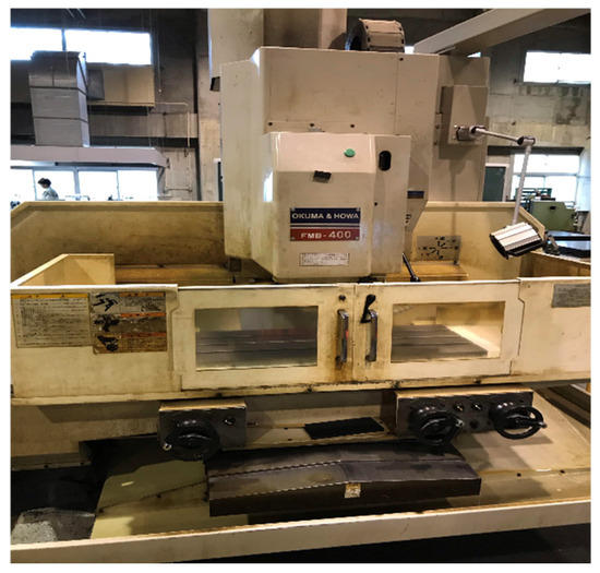
Figure 1.
NC milling machine in experimental milling.

Table 1.
Cutting oil specifications.
2.2. Cutting Tools
In this study, a four-flute solid end mill (TEFF100N4-040/30C10R16M, Tungaloy Corporation, Iwaki, Japan) for low depth of cut and high feed rate with a ball radius in the center of the cutting edge and a corner radius on the periphery was used. The tool was coated with a TiAlN layer accumulated by the PVD method. The overall view of the tool is shown in Figure 2, and the examples of aspects of the flank face and the rake face observed using an optical microscope are shown in Figure 3 and Figure 4, respectively (see Section 2.5). The tool specifications are shown in Table 2.
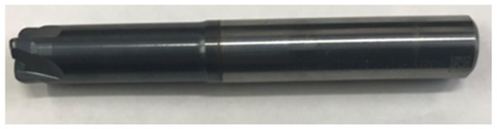
Figure 2.
Overall view of cutting tool in experimental milling.
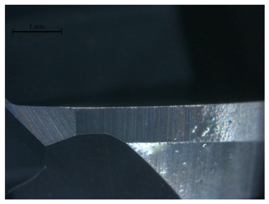
Figure 3.
Example of aspect of flank face of tool.
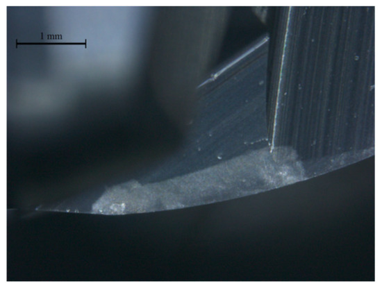
Figure 4.
Example of aspect of rake face of tool.
Table 2.
Tool specifications.
2.3. Workpiece Material
A schematic diagram of the experimental milling is shown in Figure 5. The dimensions of Inconel 718 superalloy used are width of 100 mm, length of 170 mm and thickness of 30 mm. The component ratio of Inconel 718 superalloy shown in Table 3. The main components are Ni and Cr.
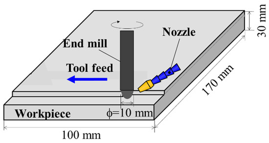
Figure 5.
Schematic diagram in experimental milling.
Table 3.
Component ratio of Inconel 718 superalloy (Wt: %).
2.4. Cutting Conditions
Milling is conducted by feeding the tool in the direction of the blue arrow, and cutting oil is injected at the cutting point by an external supply system, as shown in Figure 5. Table 4 shows the cutting conditions. The cutting speed is defined as the peripheral speed at the cutting edge boundary with a depth of cut of 0.3 mm and four cutting speeds: 10.33 m/min, 20.65 m/min, 51.65 m/min and 82.64 m/min. Each cutting speed corresponds to the rotational speed of 500 rpm, 1000 rpm, 2500 rpm and 4000 rpm. In this study, two cutting speeds of 10.33 m/min and 20.65 m/min are defined as low-speed milling and two cutting speeds of 51.65 m/min and 82.64 m/min are defined as high-speed milling. Five feed rates were used: 0.05 mm/tooth, 0.08 mm/tooth, 0.2 mm/tooth, 0.4 mm/tooth, and 1.2 mm/tooth. For reference, 0.4 mm/tooth is five to ten times the feed rate at which Inconel 718 superalloy was normally milled using a 10 mm diameter end mill. In this study, the depth of cut and the pick feed are fixed at 0.3 mm and 2 mm, respectively, and the table feed rate of the milling machine is adopted as an index of milling efficiency, defined as a value in mm/min. In order to make comparisons under the same machining efficiency conditions, four combinations of cutting speed and feed rate were set so that the table feed rate was 800 mm/min (A: 10.33 m/min and 0.4 mm/tooth, B: 20.65 m/min and 0.2 mm/tooth, C: 51.65 m/min and 0.08 mm/tooth, D: 82.64 m/min and 0.05 mm/tooth, hereafter A, B, C and D) and compare each condition. Same table feed speeds are considered to be equal in terms of milling efficiency. In addition to A, B, C and D, other combinations of cutting speeds and feed rates are also compared (hereafter E, F, G, H, I, J and K) in order to discuss the effects of cutting speeds and feed rates in detail. For simplicity, Table 5 shows the combinations of cutting speeds and feed rates. The bar areas in the table are not used in this study because they would result in low milling efficiency or tool breakage due to high loads. The cutting direction is down cutting with low cutting resistance [24].
Table 4.
Cutting conditions.
Table 5.
Combinations of cutting speeds and feed rates.
2.5. Observation Methods
The tool observation and analysis are conducted using an optical microscope (Digital microscope camera DFC400, Leica Microsystems, Wetzlar, Germany), transmission electron microscope (Miniscope TM1000, Hitachi High-Tech Corporation, Tokyo, Japan, hereafter TEM) [25], scanning electron microscope (JSM6400, JEOL Ltd., Akishima, Japan, hereafter SEM), and electron probe micro analyzer (EPMA-1720 Series, Shimadzu Corporation, Kyoto, Japan, hereafter EPMA) that irradiates the surface of a solid sample with a finely focused electron beam in a vacuum environment. This enables observation of surface microstructure and morphology, alongside localized elemental analysis at the micrometer scale [26].
The optical microscope was used to observe the flank face and rake face to measure the flank wear width and to check for the presence of chipping on the cutting edge. In this study, an observation was made from the flank face or rake face, and the experimental milling was terminated when chipping or defects with a width of 0.2 mm or more were observed on any one of the four cutting edges, as milling could not be continued. An example of chipping observation is shown in Figure 6. The area within 500 μm from the boundary of the outer circumference of the cutting edge on the flank face was observed using an optical microscope, and the experimental milling was terminated when the wear width reached 0.1 mm.
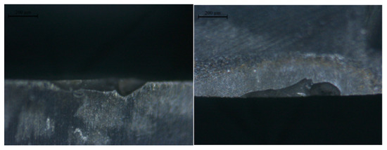
Figure 6.
Example of chipping observation.
The surface roughness, as the average arithmetic roughness (Ra) of the workpiece, was measured at a cutting length of 0.1 m using a surface roughness measuring machine (Surfcom 130A, Tokyo Seimitsu Co., Ltd., Hachioji, Japan). Ra is more effective than maximum height roughness Rz to capture the surface irregularities evenly.
EPMA was used to analyze the rake face in detail for welding and coating delamination. An example of elemental analysis of the rake face by EPMA is shown in Figure 7. The left-hand side of Figure 7a is an optical microscope image of the rake face, and Figure 7b–d are EPMA images focusing on the area surrounded by the red border of the optical microscope image; the EPMA image shows that the detection intensity increases as it moves from green to red and decreases as it moves from blue to white. The analyzed elements were Al [Figure 7b], the main component of the coating film of the tool, tungsten W [Figure 7c], the base material of the carbide tool, and nickel Ni [Figure 7d], which shows the main component of the workpiece Inconel 718 superalloy. The EPMA settings were acceleration voltage of 15 kV, beam diameter of 3 μm, a beam size of 3 μm, data points of 216 × 216, area size of 648 × 648 µm, sampling time of 40 ms and step sizes of 3 µm in X-direction and 3 µm in Y-direction. In low-speed milling, in addition to EPMA analysis of the rake face, the flank face is observed by TEM to analyze the wear and welding morphology. An example of TEM image on the flank face is shown in Figure 8. The left-hand side of the figure shows an optical microscope image of the flank face, while the right-hand side shows a TEM image focusing on the area surrounded by the red border of the optical microscope image.
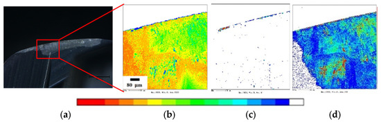
Figure 7.
Example of elemental analysis on rake face by EPMA. (a) Rake face, (b) Al, (c) W, (d) Ni.
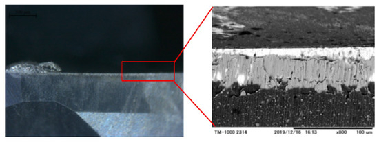
Figure 8.
Example of TEM image on flank face.
3. Experimental Results in High-Speed Milling
3.1. Tool Life in High-Speed Milling
The compared results of tool life in high-speed milling with the cutting speeds of 51.65 m/min and 82.64 m/min are shown in Figure 9. The vertical axis represents the cutting length, which is used to evaluate the tool life. The horizontal axis indicates the cutting conditions D (82.64, 0.05), J (82.64, 0.08), G (51.65, 0.05), C (51.65, 0.08) and I (51.65, 0.2), where the numbers in brackets mean the cutting speed and feed rate. Specifically, D (82.64, 0.05) represents experimental milling under the cutting speed of 82.64 m/min and a feed rate of 0.05 mm/tooth.
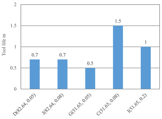
Figure 9.
Compared tool lives in high-speed milling.
In high-speed milling, chipping occurred on the tool cutting edge under all conditions, and tool life was extremely short. There was no correlation between feed rate and tool life, and it can be inferred that the formation of welding of workpiece material components due to cutting heat, chemical wear due to drop-out, and excessive tool load due to high cutting resistance lead to tool breakage in high-speed milling.
3.2. Tool Wear and Surface Roughness of Workpiece in High-Speed Milling
Figure 10 shows the relationship between cutting length and flank wear width in high-speed milling. The results show that the progression of the wear width of the flank face becomes slower as the feed rate increases in both cutting speeds. The smaller the feed rate, the more flank wear occurs at the initial observation point of 0.1 m, and the wear progresses significantly thereafter. The reason seems that the smaller the feed rate, the greater the number of times the tool tip impacts the workpiece. The progression of flank wear at 0.08 mm/tooth is moderate at low cutting speeds, while there is almost no change in wear width at 0.05 mm/tooth at different cutting speeds. The reason seems that mechanical wear due to feed rate is dominant at 0.05 mm/tooth, and chemical wear due to cutting heat is dominant at 0.08 mm/tooth.
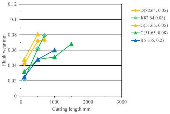
Figure 10.
Relationship between cutting length and flank wear width in high-speed milling.
The compared results of the measured surface roughness of the workpiece in high-speed milling are shown in Figure 11. A comparison in terms of cutting speeds of 82.64 m/min and 51.65 m/min shows that the surface roughness of the workpiece increases as the feed rate increases in both cutting speeds. Comparison between the figures also shows that at the same feed rate, the surface roughness of the workpiece increases as the width of the tool wear increases. It is presumed that this is due to the deterioration of the accuracy of the cutting edge caused by the progression of the flank wear.
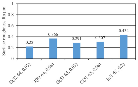
Figure 11.
Compared surface roughness of workpiece in high-speed milling.
3.3. Coating Damage and Changes in Welding of Material Components of Workpiece in High-Speed Milling
EPMA was used to compare the damage state of the tool coating film of the rake face and the change in welding of the material components of the workpiece in high-speed milling. The analyzed elements were tungsten W (the base metal of the cemented carbide tool), aluminum Al (the coating film) and nickel Ni (the main component of the workpiece). The analyzed results at a cutting length of 0.5 m are shown in Figure 12 and Figure 14, respectively, and the analyzed results at the cutting length at tool life are shown in Figure 13 and Figure 15, respectively. As the condition G (51.65, 0.05) resulted in tool life at the cutting length of 0.5 m, Figure 12 shows the same analyzed results corresponding to Figure 13. Figure 14 shows the same analyzed results corresponding to Figure 15.
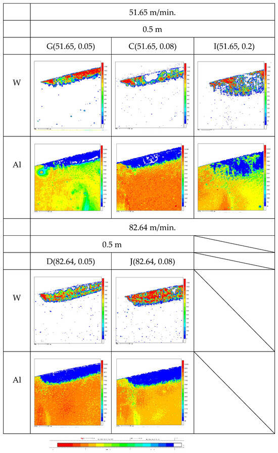
Figure 12.
Analyzed damage to coating film at cutting length of 0.5 m in high-speed milling.
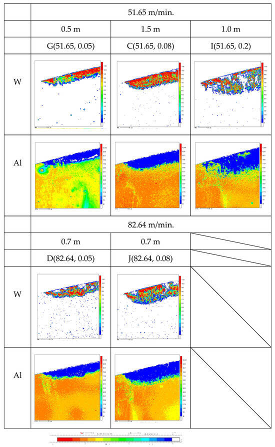
Figure 13.
Analyzed damage to coating film at cutting length of tool life end in high-speed milling.
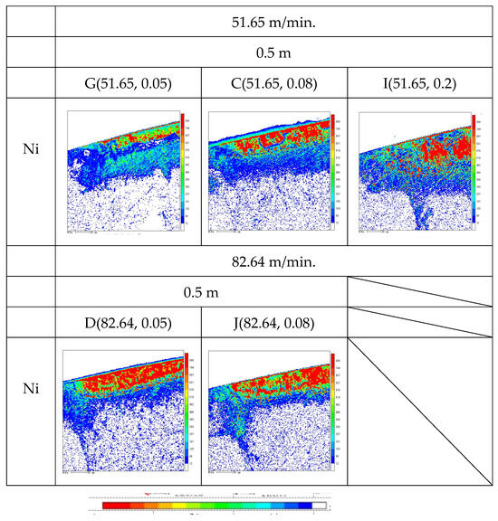
Figure 14.
Analyzed Ni adhesion of tool surface at cutting length of 0.5 m in high-speed milling.
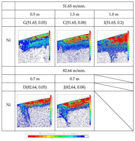
Figure 15.
Analyzed Ni adhesion of tool surface at cutting length of tool life end in high-speed milling.
The analyzed results of the Al in Figure 12 show that damage to the coating film can be confirmed for all conditions except I (51.65, 0.2) at the cutting length of 0.5 m, which remains unchanged at the end of tool life in Figure 13. However, for I (51.65, 0.2), the coating damage was partial at the cutting length of 0.5 m, but the damage spread as the cutting length increased. This suggests that under low feed rate conditions, the coating film is completely lost after a small cutting length, but increasing the feed rate can extend the life of the coating film.
The analyzed results of the Al also show that the coating damage width increases as the feed rate is increased. The contact area with the rake face is increased by increasing the feed rate, because the cutting tip is larger in the milling process. It is considered that the larger the feed rate, the cleaner the cutting edge ridge is maintained because the chips collide with the rake face mid-section. In fact, the analyzed results of W in Figure 12 and Figure 15 show that a number of welded lumps of the material components of the workpiece, indicated in white, can be observed near the cutting edge ridge in C (51.65, 0.08), D (82.64, 0.05) and J (82.64, 0.08), but almost none in I (51.65, 0.2).
Comparing C (51.65, 0.08), D (82.64, 0.05) and J (82.64, 0.08) from the analyzed results of Ni in Figure 14 and Figure 15, it can be seen that there are areas where the Ni welding decreases as the cutting length increases. This suggests that the welding is detached during the milling process. On the other hand, for I (51.65, 0.2), the area of Ni welding increases monotonically with increasing cutting length. Increasing the feed rate up to 0.2 mm/tooth suppresses the welding delamination to some extent, but at 0.05 mm/tooth and 0.08 mm/tooth, there is no significant difference, indicating that the welding delamination progresses.
From the above, it is considered that the growth and detachment of welding is the cause of chipping at small feed rates, such as 0.05 mm/tooth and 0.08 mm/tooth, in high-speed milling. It is presumed that increasing the feed rate to 0.2 mm/tooth can suppress coating damage and welding of workpiece components to some extent. However, chipping occurred at a cutting length of 1.0 m for I(51.65, 0.2), suggesting that welding was not the direct cause, but that the bonding of the tool matrix was weakened by welding, and the impact to the tool due to excessive cutting resistance was added to it, leading to tool loss.
4. Experimental Results in Low-Speed Milling
4.1. Tool Life in Low-Speed Milling
The compared results of tool life in low-speed milling (10.33 m/min, 20.65 m/min) are shown in Figure 16, as in Section 3.1, and the vertical axis represents the cutting length of the tool life. The compared six conditions are F (20.65, 0.08), B (20.65, 0.2), H (20.65, 0.4), E (10.33, 0.2), A (10.33, 0.4) and K (10.33, 1.2). The letters on the horizontal axis indicate the cutting conditions, and the numbers in brackets indicate the cutting speed and feed rate. Experimental condition K (10.33, 1.2) was additionally tested based on the results of each cutting condition in the expectation of higher efficiency, and only tool life, flank wear width, surface roughness of workpiece and the observations of the flank face were conducted using a TEM.
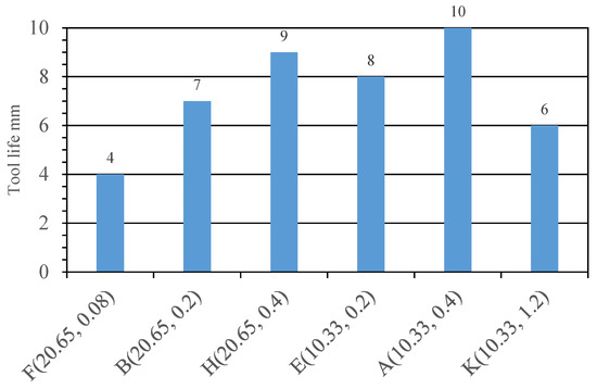
Figure 16.
Compared tool life in low-speed milling.
In low-speed milling, chipping occurred on the cutting edge at a cutting length of 7.0 m and 6.0 m for B (20.65, 0.2) and K (10.33, 1.2), respectively, and was considered to be the tool life. However, the tool life was considered as the chipping on the cutting edge reached 0.1 mm at a cutting length of 4.0 m, 9.0 m, and 8.0 m for F (20.65, 0.08), H (20.65, 0.4) and E (10.33, 0.2), respectively. The tool life was determined as the flank wear width reached 0.1 mm at cutting lengths of 4.0 m, 9.0 m and 8.0 m, respectively. In case A (10.33, 0.4), the milling was terminated because the tool wear width did not reach 0.1 m at a cutting length of 10 m. A comparison of tool life at the same cutting speeds shows that tool life increased with higher feed rate conditions, except for K (10.33, 1.2). When the tool life is compared at the same feed rate for the four conditions, B (20.65, 0.2), H (20.65, 0.4), E (10.33, 0.2) and A(10.33, 0.4), it can be seen that tool life is increased for conditions where the cutting speed is smaller. From this result, it can be inferred that if the feed rate is within a certain range, tool life can be extended by reducing the cutting speed and increasing the feed rate.
4.2. Tool Wear and Surface Roughness in Low-Speed Milling
Figure 17 shows the relationship between cutting length and flank wear width in low-speed milling (10.33 m/min, 20.65 m/min). Compared with the high-speed milling, the results showed no overall difference. Compared with a cutting speed of 20.65 m/min, the wear width at the initial stage of milling was larger for F (20.65, 0.08) with a cutting speed of 0.08 mm/tooth than for B (20.65, 0.2) and H (20.65, 0.4) with higher feed rates, and the subsequent wear rate was also larger and the flank wear progressed relatively rapidly. Compared with a cutting speed of 10.33 m/min, the flank wear progresses linearly with increasing cutting length for E (10.33, 0.2). On the other hand, for K (10.33, 1.2), the flank wear progressed gently up to a cutting length of around 4.0 m, after which the flank wear progressed rapidly and chipping occurred at 6.0 m, which was the end of tool life. It is presumed that the high cutting resistance due to the extremely high feed rate caused the tool cutting edge to drop off, resulting in rapid flank wear and ultimately chipping. In terms of the feed rate of 0.2 mm/tooth and 0.4 mm/tooth, the flank wear progression was almost the same when the feed rate was equal. However, the flank wear progressed almost linearly after a cutting length of 4.0 m for H (20.65, 0.4), while for A (10.33, 0.4), the tool wear progressed rapidly and gently from around a cutting length of 4.0 m, reaching a cutting length of 10 m as it was.
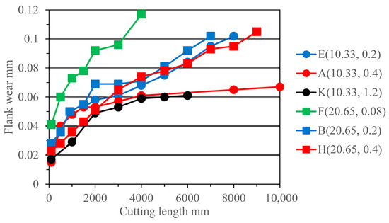
Figure 17.
Relationship between cutting length and flank wear width in low-speed milling.
The compared results of the surface roughness of the workpiece in low-speed milling (10.33 m/min and 20.65 m/min) are shown in Figure 18. The compared results in terms of cutting speeds of 10.33 m/min and 20.65 m/min show that, as in high-speed milling, the surface roughness of the workpiece increases with increasing feed rate at the same cutting speed. In particular, K (10.33, 1.2) has a feed rate three times higher than A (10.33, 0.4), but the surface roughness of the workpiece is approximately seven times larger. Compared results from the perspective of feed rates of 0.2 mm/tooth and 0.4 mm/tooth show that at the same feed rate, the surface roughness of the workpiece increases as the cutting speed increases.
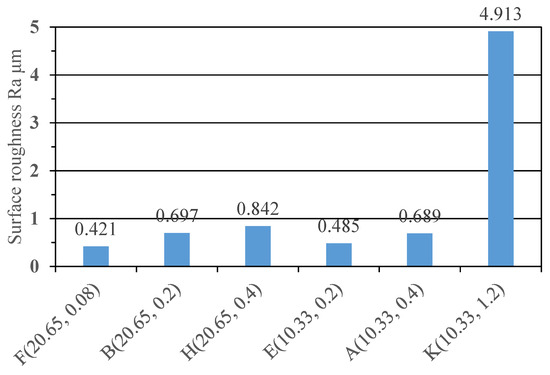
Figure 18.
Compared surface roughness of workpiece in low-speed milling.
4.3. Coating Film Damage and Changes in Welding of Workpiece Components in Low-Speed Milling Experiments
EPMA was used to compare the state of damage to the tool coating film on the rake face and the change in welding of material components of the workpiece in low-speed cutting (10.33 m/min, 20.65 m/min). The analyzed elements were tungsten W (the base metal of the cemented carbide tool), aluminum Al (the coating film) and nickel Ni (the main component of the workpiece). The analyzed results at a cutting length of 0.5 m are shown in Figure 19 and Figure 20, and those at a cutting length of 3.0 m are shown in Figure 21 and Figure 22.
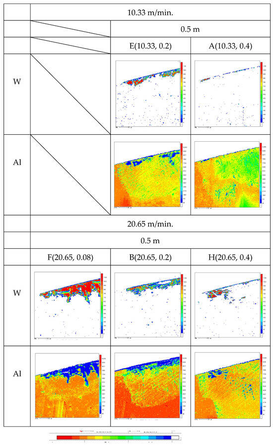
Figure 19.
Analyzed damage to coating film at cutting length of 0.5 m in low-speed milling.
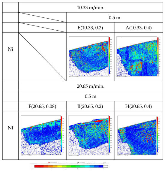
Figure 20.
Analyzed Ni adhesion of tool surface at cutting length of 0.5 m in low-speed milling.
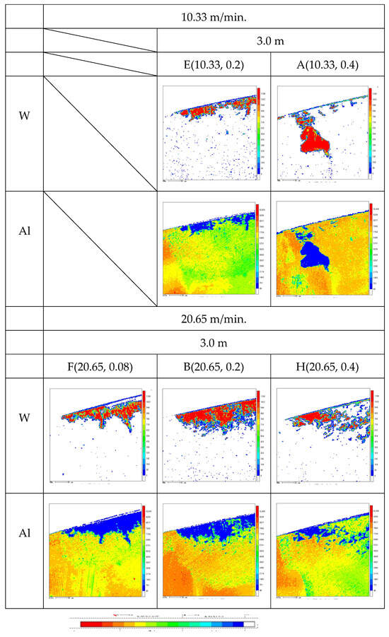
Figure 21.
Analyzed damage to coating film at cutting length of 3.0 m in low-speed milling.
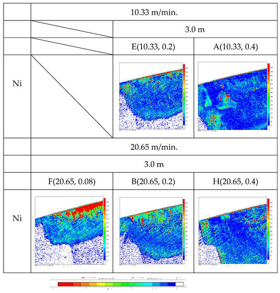
Figure 22.
Analyzed Ni adhesion of tool surface at cutting length of 3.0 m in low-speed milling.
In Figure 12, significant coating damage was shown in all conditions at a cutting length of 0.5 m in high-speed milling. On the other hand, Figure 19 showed that relatively little coating damage occurred in low-speed milling. However, it can be seen that the amount of damage varied significantly depending on the conditions: in terms of cutting speeds of 51.65 m/min and 82.64 m/min, the coating film damage became smaller as the feed rate increased. Compared results with Figure 20 also showed that the speed of coating film damage varies depending on the conditions. Specifically, there is no significant difference in coating film damage at E (10.33, 0.2) and B (20.65, 0.2) in Figure 19, while coating film damage spread significantly at B (20.65, 0.2) in Figure 20.
From Figure 20, it can be inferred that a constituent cutting edge exists along the cutting edge ridge in F (20.65, 0.08) because there is a long and narrow area along the cutting edge ridge that is not detected as W in the W analysis image, and this area is detected as a fully welded area in the analyzed Ni image in Figure 22 at (20.65, 0.08), which showed a large growth of flank wear and tool life at a cutting length of 4.0 m, suggesting that the resumption of cutting accelerated the welding of the constituent cutting edges on the edge ridge and increased flank wear. In B (20.65, 0.2), clear Ni welding was observed on the cutting edge ridge at a cutting length of 0.5 m, and coating damage spread relatively large, at a cutting length of 3.0 m. This suggests that welding tended to occur on the cutting edge ridge, leading to repeated welding formation and drop-out, and eventually to chipping. It can be inferred that welding tends to occur on the blade edge ridge, leading to repeated welding and dropout, and finally to chipping. On the other hand, checking H (20.65, 0.4), E (10.33, 0.2) and A (10.33, 0.4) in Figure 22, Ni welding was only slightly present along the cutting edge ridge at a cutting length of 3.0 m, indicating that welding could be suppressed.
4.4. Changes in Flank Wear and Welding of Material Components of Workpiece in Low-Speed Milling
In order to analyze the change in wear on the flank surface in low-speed milling (10.33 m/min, 20.65 m/min), TEM analysis was conducted on the flank face to compare the flank wear and the change in welding of the material components of the workpiece in low-speed milling. TEM images at a cutting speed of 10.33 m/min are shown in Figure 23 and at a cutting speed of 20.65 m/min in Figure 24. The upper panel shows the flank face at a cutting length of 3.0 m. The lower panel shows the flank face at the cutting length at the end of tool life. For K (10.33 1.2), only the analysis at tool life was conducted; elements can be identified in the TEM image because TEM detects elements with larger atomic numbers as white. The black areas in the image represent the coating film Al, the gray areas Ni, which is the main component of the workpiece material, and the white areas W, which is the tool matrix.
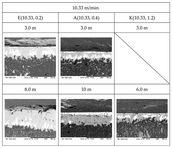
Figure 23.
TEM image of flank face with change in cutting length at cutting speed of 10.33 m/min.
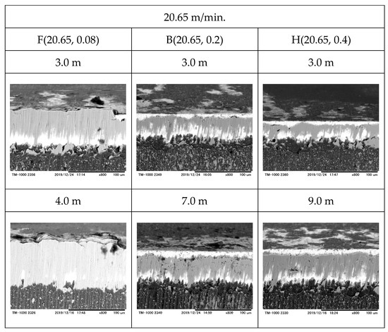
Figure 24.
TEM image of flank face with change in cutting length at cutting speed of 20.65 m/min.
From Figure 23 and Figure 24, it can be seen that Ni welding becomes more pronounced as the feed rate is reduced in both cutting speeds: for F (20.65, 0.08), a build-up edge can be seen on the flank face at a cutting length of 3.0 m. At a cutting length of 4.0 m, the area that was partially welded at a cutting length of 3.0 m has grown to a fully welded area. The area that was partially welded at a cutting length of 3.0 m grew and became a fully welded area. On the other hand, for E (10.33, 0.2), no significant welding was observed on the clearance surface at a cutting length of 3.0 m, but at a cutting length of 8.0 m, the welding grew. Since almost no Ni welding was observed on the rake face at a cutting length of 3.0 m, it can be inferred that welding was at least formed on the flank face after a cutting length of 3.0 m and then gradually grew. In addition, Figure 23, A (10.33, 0.4) shows that at a cutting length of 10 m, the Ni width was larger than at a cutting length of 3.0 m and reached the boundary with the coating film. On the other hand, for B (20.65, 0.2) and H (20.65, 0.4) in Figure 24, there is no significant difference in the flank wear compared to A (10.33, 0.4) at a cutting length of 3.0 m. However, B (20.65, 0.2) and H (20.65, 0.4) show more flank wear at a cutting length of 7.0 m and at 9.0 m, respectively. The flank wear progressed to more than A (10.33, 0.4) at a cutting length of 9.0 m, indicating that the tool matrix was exposed at the boundary with the coating film. Therefore, it can be considered that at A (10.33, 0.4), B (20.65, 0.2) and H (20.65, 0.4), the welding on the flank face gradually laminates and delaminates, simultaneously delaminating the coating film and increasing the flank wear. In addition, this wear pattern progressed faster for B (20.65, 0.2) and H (20.65, 0.4) than for A (10.33, 0.4), with K (10.33, 1.2) showing the lowest wear width and Ni welding at a cutting length of 6.0 m in tool life. The main reason for chipping in K (10.33, 1.2) seemed not to be Ni welding, but a strong impact on the tool edge due to the high feed rate.
From the above, under the conditions of low-cutting speed and high feed rate in low-speed milling, Ni welding on the tool edge ridge and the built-up edge can be suppressed, and the increase in flank wear can be reduced.
5. Discussion
Based on the results of the experimental milling in Section 3 and Section 4, the cutting conditions under which highly efficient milling is possible under the cutting conditions of this study are discussed. The relationship between the table tool feed and cutting conditions is shown in Figure 25. The vertical axis in Figure 25 represents the table feed rate, which is used as an index of milling efficiency. The unit is mm/min, and the horizontal axis is each experimental condition compared in this study.
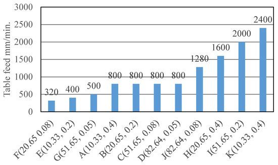
Figure 25.
Relationship between table tool feed and cutting conditions.
The milling efficiencies of A (10.33, 0.4), B (20.65, 0.2), C (51.65, 0.08) and D (82.64, 0.05) were equal to 800 mm/min, but C (51.65, 0.08) and D (82.64, 0.05) in high-speed milling showed severe welding and detaching of the material components of the workpiece in the early stages of cutting. On the other hand, A (10.33, 0.4) and B (20.65, 0.2) in low-speed milling showed relatively long tool life, with A (10.33, 0.4) having an especially small amount of welding on the flank face, and the width of the rake face and the flank face was the smallest at a cutting length of 10 m. This is a condition that enables both long tool life and highly efficient milling.
More efficient milling can be expected for J (82.64, 0.08), H (20.65, 0.4), I (51.65, 0.2) and K (10.33, 1.2) compared with A (10.33, 0.4). However, J (82.64, 0.08) and I (51.65, 0.2) in high-speed milling, as well as C (51.65, 0.08) and D (82.64, 0.05), show shorter tool life due to welding of the material components of the workpiece. On the other hand, H (20.65, 0.4) causes faster flank wear than A (10.33, 0.4), but doubles the milling efficiency to 1600 mm/min. However, this is not a good condition because the high impact on the tool cutting edge due to the high feed rate causes damage to the cutting edge, and the surface roughness of the workpiece is approximately nine times higher than that of A (10.33, 0.4).
As a result, it is concluded that both long tool life and highly efficient milling are possible under conditions where the cutting speed is low and the feed rate is high, as in A (10.33, 0.4) and H (20.65, 0.4). However, since the surface roughness of the workpiece increases in A (10.33, 0.4) and H (20.65, 0.4), as shown in Figure 18 and as mentioned above, the surface quality deteriorates.
The limited results are available for long tool life and highly efficient milling within a certain range because the results may differ from those using a larger diameter, different coatings, and coolant use.
6. Conclusions
The results of the milling of Inconel 718 superalloy using coated cemented carbide tools at different cutting speeds and feed rates revealed the following remarks:
- (1)
- A low-cutting speed and a high feed rate per edge suppresses damage to the coating film and delays the cycle of welding and shedding of the material components of the workpiece, leading to a longer tool life, and thus highly efficient milling can be expected.
- (2)
- At cutting speeds of 51.65 m/min and 82.64 m/min, the life extension of the tool by the coating film is slight: at small feed rates such as 0.05 mm/tooth and 0.08 mm/tooth, the welding of the material components of the workpiece is dense near the rake face cutting edge ridge. This welding grows and peels off, causing chipping. Increasing the feed rate to 0.2 mm/tooth can suppress coating damage and welding of the material components of the workpiece to some extent.
- (3)
- At cutting speeds of 10.33 m/min and 20.65 m/min, the welding of the material components of the workpiece on the flank face of the tool becomes more pronounced as the feed rate is reduced, but the welding stacking becomes milder as the cutting speed is reduced. 0.4 mm/tooth can suppress welding on both the rake face and flank face and prevent the increase in wear width to some extent. 0.4 mm/tooth can suppress welding on both the rake face and flank face and prevent an increase in the wear width to some extent.
When the results are applied to the complex shape structure of Inconel 718 superalloy, such as aircraft turbine blades and gas turbines in the future, efficient milling of these will be more and more effective.
Funding
This research received no external funding.
Data Availability Statement
Data is contained within the article.
Conflicts of Interest
The authors declare no conflict of interest.
References
- Roy, S.; Kumar, R.; Panda, A.; Das, R.K. A Brief Review on Machining of Inconel 718. Mater. Proc. 2018, 5, 18664–18673. [Google Scholar] [CrossRef]
- Hosseini, E.; Popovich, V.A. A review of mechanical properties of additively manufactured Inconel 718. Addit. Manuf. 2019, 30, 100877. [Google Scholar] [CrossRef]
- Bartolomeis, A.D.; Newman, S.T.; Jawahir, I.S.; Biermann, D.; Shokrani, A. Future research directions in the machining of Inconel 718. J. Mater. Process. Technol. 2021, 297, 117260. [Google Scholar] [CrossRef]
- Arriola, I.; Whitenton, E.; Heigel, J.; Arrazola, P.J. Relationship between machinability index and in-process parameters during orthogonal cutting of steels. CIRP Ann. 2011, 60, 93–96. [Google Scholar] [CrossRef]
- Liu, H.; Han, H.; Jiang, Q.; Zhang, B. Mechanisms in the machinability improvement of Inconel 718 superalloy through ultra-high-speed grinding. J. Mater. Process. Technol. 2024, 333, 118614. [Google Scholar] [CrossRef]
- Khana, M.A.; Ahmad, R.; Jaffery, D.H.I.; Butt, S.I.; Khan, M.S.; Zahid, D. Sustainability analysis of tool wear, energy efficiency, surface quality, and energy during dry, MQL, and wet turning of Inconel 718. Int. J. Sustain. Energy 2025, 44, 2515447. [Google Scholar] [CrossRef]
- Peng, Z.; Zhang, X.; Zhang, Y.; Liu, L.; Xu, G.; Wang, G.; Zhao, M. Wear resistance enhancement of Inconel 718 via high-speed ultrasonic vibration cutting and associated surface integrity evaluation under high-pressure coolant supply. Wear 2023, 530–531, 205027. [Google Scholar] [CrossRef]
- Finkeldei, D.; Sexauer, M.; Bleicher, F. End milling of Inconel 718 using solid Si3N4 ceramic cutting tools. Procedia CIRP 2019, 81, 1131–1135. [Google Scholar] [CrossRef]
- Amin, A.N.; Khatun, S.; Saba, T.; Iqbal, M.; Rumi, M.J.U. High-speed machining of INCONEL 718: Enhancing surface roughness and tool life using TiN-coated carbide tools. Int. J. Adv. Manuf. Technol. 2025, 138, 1965–1994. [Google Scholar] [CrossRef]
- Hao, T.; Du, J.; Su, G.; Zhang, P.; Sun, Y.; Zhang, J. Mechanical and cutting performance of cemented carbide tools with Cr/x/DLC composite coatings. Int. J. Adv. Manuf. Technol. 2020, 106, 5241–5254. [Google Scholar] [CrossRef]
- Kawakami, M. Cemented carbide tools and moulds for wear-resistant applications in Japan. Int. J. Refract. Met. Hard Mater. 2024, 118, 106477. [Google Scholar] [CrossRef]
- Liu, H.; Wu, W.; Zhang, D. Feasibility study of high-efficiency self-excited vibration cutting for roughing Inconel 718. J. Mater. Res. Technol. 2025, 35, 1429–1451. [Google Scholar] [CrossRef]
- Jacquet, T.; Fromentin, G.; Viprey, D.P.F. Modeling of high-feed milling and surface quality applied to Inconel 718. Procedia CIRP 2024, 123, 113–118. [Google Scholar] [CrossRef]
- Sebbe, N.P.V.; Silva, F.J.G.; Durão, L.M.; Jesus, A.; Sales-Contini, R.C.M. Comparative analysis of the wear behavior of TiN/TiAlN-, TiAlVN-, and TiAlYN-coated tools in milling operations of Inconel 718. ASME J. Tribol. 2025, 147, 074202. [Google Scholar] [CrossRef]
- Silva, F.J.G.; Sebbe, N.P.V.; Costa, R.D.F.S.; Pedroso, A.F.V.; Sales-Contini, R.C.M.; Barbosa, M.L.S.; Martinho, R.P. Investigations on the surface integrity and wear mechanisms of TiAlYN-coated tools in Inconel 718 milling operations. Materials 2024, 17, 443. [Google Scholar] [CrossRef]
- Sebbe, N.P.V.; Albuquerque, J.; Sousa, V.F.C.; Fernandes, F.; Silva, F.J.G.; Sales-Contini, R.C.M.; Pedroso, A.F.V.; Martinho, R. Investigations on tool wear behavior of TiAlVN and TiAlN/TiAlVN coated tools in the milling Inconel 718. ASME J. Tribol. 2024, 146, 121402. [Google Scholar] [CrossRef]
- Sebbe, N.P.; Fernandes, F.; Silva, F.J.; Pedroso, A.F.; Sales-Contini, R.C.; Barbosa, M.L.; Durão, L.M.; Magalhães, L.L. Wear behavior of TiAlVN-coated tools in milling operations of INCONEL® 718. Coatings 2024, 14, 14030311. [Google Scholar] [CrossRef]
- Pedroso, A.F.; Sousa, V.F.; Sebbe, N.P.; Silva, F.J.; Campilho, R.D.; Martinho, R.P.; de Jesus, A.M.; Sales-Contini, R.C. Sales-Contini. Cooling and lubricating strategies for INCONEL® alloys machining: A comprehensive Review on recent advances. ASME J. Tribol. 2025, 147, 060801. [Google Scholar] [CrossRef]
- Fortes, R.C.; Pereira, I.C.; Guimarães, G.P.; Silva, M.B.D. A new experimental procedure for investigating built-up edge formation through chip analysis in AISI 1050 steel. Int. J. Adv. Manuf. Technol. 2025, 139, 869–877. [Google Scholar] [CrossRef]
- Seid Ahmed, Y.; Fox-Rabinovich, G.; Mario Paiva, J.; Wagg, T.; Clarence Veldhuis, S. Effect of Built-Up Edge Formation during Stable State of Wear in AISI 304 Stainless Steel on Machining Performance and Surface Integrity of the Machined Part. Materials 2017, 10, 1230. [Google Scholar] [CrossRef]
- Song, X.; Takahashi, Y.; He, W.; Ihara, T. Effects of the size of built-up layer on the wear of cemented carbide tools in cutting of SUS304 stainless steel. JSME J. Adv. Mech. Des. Syst. Manuf. 2021, 15, JAMDSM0050. [Google Scholar] [CrossRef]
- Kawasaki, K. High-speed milling of Inconel 625 alloy using carbide end mills. J. Mech. Sci. Technol. 2022, 36, 6239–6245. [Google Scholar] [CrossRef]
- Liu, D.; Liu, Z.; Wang, B. Effect of Cutting Parameters on Tool Chipping Mechanism and Tool Wear Multi-Patterns in Face Milling Inconel 718. Lubricants 2022, 10, 218. [Google Scholar] [CrossRef]
- Hadi, M.; Ghani, J.; Haron, C.C.; Kasim, M. Comparison between Up-milling and Down-milling Operations on Tool Wear in Milling Inconel 718. Procedia Eng. 2013, 68, 647–653. [Google Scholar] [CrossRef]
- Lovet, L.; Moy, A.; Pinard, P.T.; Fournelle, J.H. Electron probe microanalysis: A review of recent developments and applications in materials science and engineering. Prog. Mater. Sci. 2021, 116, 100673. [Google Scholar] [CrossRef]
- Libera, M.R.; Egerton, R.F. Advances in the Transmission Electron Microscopy of Polymers. Polym. Rev. 2010, 50, 321–339. [Google Scholar] [CrossRef]


Disclaimer/Publisher’s Note: The statements, opinions and data contained in all publications are solely those of the individual author(s) and contributor(s) and not of MDPI and/or the editor(s). MDPI and/or the editor(s) disclaim responsibility for any injury to people or property resulting from any ideas, methods, instructions or products referred to in the content. |
© 2025 by the author. Licensee MDPI, Basel, Switzerland. This article is an open access article distributed under the terms and conditions of the Creative Commons Attribution (CC BY) license (https://creativecommons.org/licenses/by/4.0/).