Abstract
This study introduces an autonomous framework for grasping moving objects on a conveyor belt, enabling unsupervised detection, grasping, and categorization. The work focuses on two common object shapes—cylindrical cans and rectangular cartons—transported at a constant speed of 3–7 cm/s on the conveyor, emulating typical scenarios. The proposed framework combines a vision-based neural network for object detection, a target localization algorithm, and a deep reinforcement learning model for robotic control. Specifically, a YOLO-based neural network was employed to detect the 2D position of target objects. These positions are then converted to 3D coordinates, followed by pose estimation and error correction. A Proximal Policy Optimization (PPO) algorithm was then used to provide continuous control decisions for the robotic arm. A tailored reinforcement learning environment was developed using the Gymnasium interface. Training and validation were conducted on a 7-degree-of-freedom (7-DOF) robotic arm model in the PyBullet physics simulation engine. By leveraging transfer learning and curriculum learning strategies, the robotic agent effectively learned to grasp multiple categories of moving objects. Simulation experiments and randomized trials show that the proposed method enables the 7-DOF robotic arm to consistently grasp conveyor belt objects, achieving an approximately 80% success rate at conveyor speeds of 0.03–0.07 m/s. These results demonstrate the potential of the framework for deployment in automated handling applications.
1. Introduction
Robotic arms are core actuating units in automated systems and play a vital role in industrial manufacturing, logistics, household services, and specialized operations. Their ability to autonomously grasp and place objects is the key to achieving efficient and intelligent production and service processes. In particular, conveyor belt systems are widely adopted in industrial assembly lines due to their efficiency and continuous operation. However, conventional robotic systems often rely on structured environments and are typically designed to grasp static objects with fixed positions and known poses. When confronted with dynamically moving objects on a conveyor—such as cans or paper cartons—with varying velocities and random poses, traditional pre-programmed or simple vision-based control strategies struggle with real-time responsiveness, robustness, and adaptability. Recent advances in computer vision, especially deep learning-based neural network models for object detection [1,2], have greatly improved robotic perception of dynamic environments. Concurrently, breakthroughs in artificial intelligence, particularly Reinforcement Learning (RL), have opened new avenues for solving complex decision-making and control problems. These developments enable robotic arms to perform precise manipulation tasks in uncertain and dynamic scenarios by learning through trial-and-error interactions with their environments.
Numerous strategies have been developed for robotic grasping controls. Classical approaches predominantly rely on precise environmental modeling and predefined trajectory planning through inverse kinematics. Although effective in structured settings, these approaches lack adaptability when object positions, orientations, or environmental conditions vary. An alternative direction employs machine learning to support grasp planning, typically by training models on large annotated datasets to predict the grasp points or object poses. For example, Akinola et al. [3] proposed a method that leverages a grasp database of approximately 5000 samples combined with a Recurrent Neural Network (RNN) to predict the trajectories of moving objects during grasping. Although such methods demonstrate promising outcomes, their generalization capacity and decision-making efficiency remain constrained in dynamic and time-critical scenarios.
Achieving autonomous robotic grasping in dynamic environments, such as conveyor systems, places stringent requirements on control strategies. RL, which enables agents to acquire optimal policies through trial-and-error interactions with the environment, has demonstrated significant potential in this domain [4,5,6]. A notable strength of RL lies in its ability to learn end-to-end control strategies directly from raw observations within continuous action spaces, thereby allowing robots to build an internal representation of the environment and target objects. This paradigm parallels human skill acquisition, where behavior is progressively refined through experiential feedback and shaped by reward signals, enabling agents to form task-specific neural mappings.
For instance, Chen et al. [7] proposed a method that integrated YOLO with Soft Actor-Critic (SAC) to grasp static desktop objects, whereas Pane et al. [8] demonstrated that RL-based tracking control surpasses traditional proportional–derivative (PD) and model predictive control (MPC) approaches in terms of accuracy. Nonetheless, grasping tasks involving moving objects, occlusions, or cluttered backgrounds continue to pose significant challenges. A distinct advantage of RL is that training can be conducted safely and efficiently in high-fidelity simulation environments, thereby mitigating the equipment wear, safety risks, and operational costs inherent to real-world robotic experiments. The maturity of physics-based simulators such as PyBullet and Gazebo provides a robust foundation for RL deployment in robotics. For example, Zamora et al. [9] combined OpenAI Gym with Gazebo and ROS (Robot Operating System) for robotic learning, Kaup et al. [10] reviewed common physics engines for RL research, and Panerati et al. [11] investigated multi-agent quadcopter control using PyBullet.
To meet the requirements for autonomous classification, grasping, and placement of randomly oriented moving objects on conveyor systems, we propose a novel robotic grasping framework that integrates advanced visual perception with deep reinforcement learning. The foundation of this approach is a unified control architecture that incorporates the following capabilities:
Object Detection: A high-performance You Only Look Once (YOLO) neural network detects multiple object categories (e.g., soda cans and paper cartons) on the conveyor in real time, yielding pixel-level 2D positions and class labels [12,13,14].
Pose Estimation: A customized object localization algorithm converts 2D bounding box data into 3D world coordinates by integrating camera calibration models and prior scene information. This step encompasses object pose estimation and visual error compensation.
RL Observation and Control: The processed object state (category, 3D position, orientation) is fused with the internal state of the robotic arm (e.g., joint angles, end-effector pose) to construct the observation space for the reinforcement learning agent.
We evaluated four state-of-the-art reinforcement learning algorithms—Proximal Policy Optimization (PPO), Soft Actor-Critic (SAC), Deep Deterministic Policy Gradient (DDPG), and Twin Delayed Deep Deterministic Policy Gradient (TD3)—for comparative analysis [15,16,17,18]. A customized reinforcement learning environment was implemented using the Gymnasium interface, and training was conducted using a 7-degree-of-freedom (7-DOF) robotic arm model in the PyBullet physics simulation engine [19,20].
To improve learning efficiency and generalization under diverse object types and increasing task complexity, we incorporated transfer learning and curriculum learning strategies. Simulation experiments and randomized trials validated the effectiveness of the proposed approach, showing that the framework produces smooth, collision-free trajectories and successfully accomplishes object detection, grasping, and sorting in conveyor-based dynamic scenarios. These results demonstrate that this framework achieves a ≥80% success rate at conveyor speeds of 0.03–0.07 m/s, making it a viable solution for bulk item handling tasks within these performance parameters.
The primary contributions of this study are as follows:
We designed a reinforcement learning framework specifically tailored for 7-DOF robotic manipulators to autonomously grasp conveyor-borne objects using visual perception.
We introduced an effective integration strategy that combines RGB-D camera data with YOLO-based object detection to construct reinforcement learning observation spaces, explicitly addressing challenges such as sensor noise and partial observability.
We conducted extensive simulation experiments, which demonstrated that the proposed method enables the manipulator to track moving objects on a conveyor at speeds of up to 0.07 m/s with ≥80% success rate, while maintaining an average grasping positional error within 0.03 m of the object center.
The remainder of this paper is organized as follows. Section 2 introduces the system architecture and the problem formulation. Section 3, Section 4 and Section 5 present the methodology, including model design and reward function configuration. Section 6 describes the experimental setup and results. Section 7 concludes the paper and outlines potential directions for future research.
2. Framework
This paper proposes a robotic grasping framework designed to manipulate objects moving at a constant velocity on a conveyor belt. The framework integrates a YOLO-based deep neural network for real-time object detection with a deep reinforcement learning (DRL) algorithm for robotic control, which depicts a schematic of the robotic system performing classification-driven grasping of conveyor-borne targets. As shown in Figure 1, the YOLO network processes images captured by a fixed-position camera and outputs bounding box vertices together with class labels derived from pretrained categories. These 2D detections are subsequently fused with depth-camera data and camera calibration parameters (intrinsic and extrinsic) to calculate the 3D position of the target in the world coordinate frame, along with its orientation about the Z-axis (yaw angle denoted by w). The resulting observation vector consists of the object class (obj_cls), its 3D position, and pose information. This vector is further combined with the robot’s kinematic state, including the joint angles (θᵢ) and end-effector position, to construct the input for the reinforcement learning model.
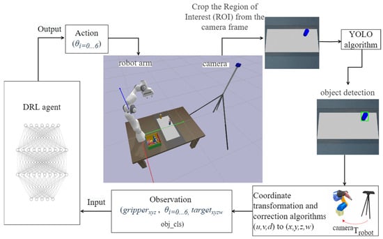
Figure 1.
Schematic diagram of the robotic grasp system employing computer vision and deep reinforcement learning.
The trained reinforcement learning agent subsequently generated control commands corresponding to the rotation angles of the six actuated joints of the 7-DOF robotic arm. Following each decision step, the agent receives feedback from the environment and computes a dynamic reward using a custom-designed reward function, which directs the learning process. This decision-making cycle was repeated iteratively until the grasping task is completed. Upon successful grasping, the system employs YOLO-derived category information to determine the placement destination of the object. Because placement at predefined locations is comparatively less complex than grasping moving targets—particularly in obstacle-free scenarios—the placement stage is simplified to reduce training duration and model complexity. The placement phase is decomposed into a set of pre-defined waypoints, rather than applying reinforcement learning to the entire manipulation sequence. The corresponding joint angles were calculated using classical inverse kinematics, and the robotic arm trajectory is generated via interpolation. The placement task is then executed through conventional motion control algorithms.
3. Object Detection Based on YOLOv8n-OBB Algorithm
In dynamic conveyor-based grasping scenarios, the robotic arm must precisely estimate both the spatial position and orientation of the target object—particularly its in-plane rotation about the Z-axis. Conventional convolutional neural network (CNN)-based detectors, such as the standard YOLO series, generally employ axis-aligned bounding boxes (AABB) to localize objects. The standard output format is (obj_cls, x, y, w, h), where (x, y) corresponds to the top-left corner of the bounding box, and (w, h) denote the width and height.
However, axis-aligned bounding boxes exhibit critical limitations:
Lack of pose information: AABBs do not encode in-plane rotation, which prevents the robotic gripper from aligning its grasping pose with the object’s orientation. This misalignment often results in grasp failures, particularly for rectangular cartons with rotation angles around the Z-axis.
Background interference: For elongated or diagonally positioned objects—such as paper cartons on a conveyor, AABBs frequently enclose a large proportion of background pixels, thereby reducing localization precision.
To overcome these limitations, this study adopted Oriented Object Detection (OOD) [21,22,23]. OOD extends the bounding box representation by regressing not only the object category and position but also its rotation angle. Common OOD parameterizations include:
The rotated rectangle representation: (obj_cls, x_c, y_c, w, h, θ) denotes the center of the rotated bounding box and θ represents the rotation angle (typically within [−90°, 90°]); or quadrilateral representation: (obj_cls, ), which directly describes the object outline using the coordinates of its four corners.
Owing to its superior performance in real-time detection, accuracy, and architectural scalability, we adopted YOLOv8n-OBB (YOLOv8 Nano with Oriented Bounding Boxes) as the core detector in our framework [24,25,26]. This algorithm, provided as an open-source implementation by Ultralytics, was specifically optimized for oriented object detection. Its architecture is illustrated in Figure 2 (obj_cls represents C).
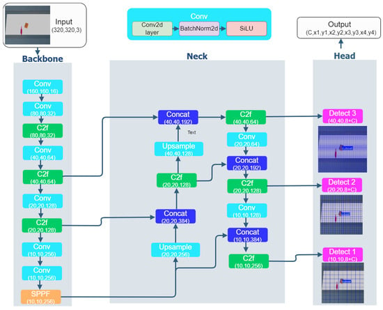
Figure 2.
The architecture of the YOLOv8n-OBB model.
The YOLOv8n-OBB network comprises three principal components: The Backbone, the Neck, and the Head.
The Backbone is dedicated to multi-scale feature extraction and is constructed on an enhanced CSPDarknet (Cross Stage Partial Darknet) structure. Its core innovation is the replacement of the C3 (Cross stage partial bottleneck with 3 convolutions) module with the C2f (Cross stage partial bottleneck with 2 convolutions and a fusion of the stages) module, which introduces additional branch connections into the gradient flow (see Figure 3). This modification improves the feature reuse and gradient propagation efficiency while simultaneously reducing redundant convolutional operations. Furthermore, the Backbone incorporates a SPPF (Spatial Pyramid Pooling Fast) module instead of the earlier standard SPP (Spatial Pyramid Pooling), thereby enhancing processing speed and receptive field.
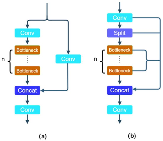
Figure 3.
The architecture of the C3 (a) and C2f (b)module.
The Neck module integrates a Feature Pyramid Network (FPN) [27] with a Path Aggregation Network (PAN) to fuse multi-scale features. This bidirectional fusion combines high-level semantic information from the backbone with low-level details from earlier layers, thereby improving the robustness in detecting small or partially occluded objects.
4. 3D Localization and Error Compensation Algorithm
As discussed in Section 3, the YOLOv8n-OBB algorithm produces either 2D pixel coordinates (u, v) with an in-plane rotation angle θ, or alternatively, the four corner points of an oriented bounding box. However, robotic grasping necessitates the position of the object and orientation expressed in the coordinate of the robot frame rather than in the image coordinates. To accomplish this transformation, we employed the following localization pipeline:
First, hand-eye calibration was performed to obtain the rigid transformation matrix between the RGB-D camera and robot base frame, where denotes the transformation from the camera coordinate system to the robot coordinate system.
Subsequently, the depth map from the RGB-D camera was used to project the 2D pixel coordinates into a 3D point ) within the camera coordinate system.
Finally, the point was subsequently transformed into the robot base frame as using the rigid body transformation .
The coordinate transformation process is defined as Equation (1):
where the 3D point in the camera frame, = (X, Y, Z), is computed from the pixel coordinates and depth value d as shown in Equation (2):
Here, () are the optical center coordinates, (,) are the focal lengths of the camera, obtained through intrinsic calibration, and represents the depth value measured by the RGB-D sensor after calibration.
Despite the relatively high detection accuracy of YOLO, several sources of systematic error may compromise localization precision: First, for cylindrical objects (e.g., soda cans), the geometric center of the bounding box predicted by YOLOv8n-OBB may deviate from the physical centroid, leading to lateral displacement. Second, image preprocessing and compression during inference may introduce pixel quantization noise. Third, our custom training dataset used for YOLO may contain annotation inaccuracies, particularly when labeling irregularly shaped objects.
To mitigate these issues, we constructed a dataset of 200 grasping instances involving cylindrical objects (radius: 0.02–0.03 m, height: 0.08–0.12 m) moving along the conveyor belt (as shown in Figure 4). This dataset was explicitly split into two independent sets: 100 instances were used for training the bias regressor, and the remaining 100 instances were held out as a validation set for evaluation, ensuring no data leakage and a robust assessment of model generalization. The observed error trends were as follows: The X-axis error increased linearly with the distance from the camera. The Y-axis error remained relatively stable with a mean of 0.0071 m. The Z-axis error was minimal, with an average of approximately 0.002 m.
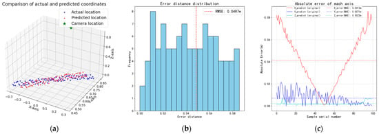
Figure 4.
The prediction error in the task. (a) displays algorithmic predictions versus ground-truth positions for 100 sampled 3D points; (b) shows the frequency distribution of Euclidean distance errors between predictions and ground-truth positions, reported in terms of Root Mean Squared Error (RMSE); (c) illustrates prediction errors along each coordinate axis, together with the corresponding Mean Absolute Errors (MAE) relative to ground-truth values.
Based on these observations, we developed a linear regression model to compensate for the localization errors in Equation (3):
where denotes the corrected prediction, () are the original predicted coordinates, and are regression coefficients estimated via supervised fitting on the training dataset.
Following correction, the Root Mean Squared Error (RMSE) of the predicted Euclidean distance errors was reduced from 0.0487 m (Figure 4b) to 0.0056 m on the independent validation set (Figure 5b). The per-axis performance of the corrected model on the independent validation set is quantified in Table 1, which reports the mean bias and standard deviation for the independent validation set. These results confirmed that the positional accuracy requirements for successful gripper alignment and grasping were satisfied.
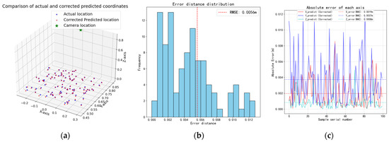
Figure 5.
Improvement in the prediction error after the correction. (a) displays the corrected predictions versus ground-truth positions on the independent validation set in 3D space; (b) shows the frequency distribution of Euclidean distance errors between corrected predictions and ground-truth positions, reported in terms of RMSE; (c) illustrates the corrected prediction errors along each coordinate axis, together with the corresponding MAE relative to ground-truth values.

Table 1.
Per-axis bias and standard deviation of the corrected pose estimation on the independent validation set (N = 100).
5. Robot Arm Grasp Policy Based on PPO Algorithm
5.1. PPO Algorithm in This Task
PPO is a deep reinforcement learning algorithm built on the Actor–Critic framework, offering several key advantages: (1) Online learning capability: PPO collects experience through real-time interaction with the environment, eliminating the need for large volumes of pre-stored historical data. (2) Stable policy updates: A clipped surrogate objective constrains the magnitude of the policy updates, preventing training divergence. (3) Parameter efficiency: PPO employs a single policy (Actor) network and a single value (Critic) network sharing a common feature extraction backbone, thereby reducing the total number of parameters.
For robotic arm training with reinforcement learning, the state space is formulated as a continuous 15-dimensional vector consisting of:
- (1)
- seven joint angles of the robotic arm;
- (2)
- three-dimensional gripper position;
- (3)
- one-dimensional object category label;
- (4)
- three-dimensional object position;
- (5)
- one-dimensional object orientation angle (w).
The state corresponding to time t as described by Equation (4):
This vector serves as the observational input to the reinforcement learning environment. The action space corresponds to incremental adjustments in the seven joint angles relative to their previous values in the observation space. These increments represent fine-grained rotational modifications executed by the robotic arm in response to perceived environmental states.
And the action corresponding to time t as described by Equation (5):
Both the states and actions in the reinforcement learning environment lie in a continuous domain. Accordingly, PPO employs neural networks to parameterize both the policy function and the value function. The value network, denoted as , and the policy network, represented as , utilize the parameters of vectors and respectively. The policy network generates a probability distribution over potential actions given the current state, enabling action selection according to the learned policy. The value network facilitates evaluation of expected cumulative rewards for different states, thereby guiding policy refinement. Estimation of the value function is accomplished through a dedicated neural network parameterized by .
During reinforcement learning, the policy function outputs actions based on the current observed state, subsequently transitioning the system to new states. Through iterative interactions with the environment, both the policy network Actor and value network Critic undergo continuous optimization.
The objective function of the policy network is defined by Equation (6), which incorporates a trust region constraint via the clipped importance sampling ratio. The policy network , shares identical architecture with the old policy . The former generates new policies whereas the latter serves as a behavior policy for historical action probability estimation. During training, only is updated, with periodically synchronized from the current policy parameters, and the policy network objective function calculated by using Equation (6) [15]:
where the importance sampling ratio is calculated by Equation (7):
The advantage function is computed via the GAE (Generalized Advantage Estimation) in Equation (8), where denotes the bias-variance trade-off coefficient and is the discount factor:
The state-value function is updated using the target (Equation (9)) with the MSE (Mean Square Error) in Equation (10):
Then policy and value networks are alternately optimized using the Adam optimizer in Equations (11) and (12):
The parameters of the old policy and value networks are updated every K iterations,
The hyperparameter is learning rate, as given in Equation (13):
Algorithm 1 illustrates the procedure of PPO.
| Algorithm 1: Proximal Policy Optimization Algorithm (Pseudocode) |
|
5.2. Reward Design
This study applies the PPO to robotic object grasping in dynamic conveyor environments. The learning agent is a 7-DOF robotic manipulator, whose policy outputs continuous joint-space actions . The state representation , action space (defined in Section 5.1), and the reward mechanism is designed as described below:
The reward mechanism is defined in Equation (14). In this task, the region within 3 cm of the target is designated as the pre-grasp zone. To incentivize the RL agent to continually guide the gripper toward the moving target, we introduce a distance-based reward: if the gripper–target distance decreases compared with the previous time step, the agent receives a positive reward proportional to the reduction (Δd × 1000); otherwise, a penalty is applied. This formulation encourages the manipulator to converge steadily toward the target.
Furthermore, if the gripper reaches the pre-grasp zone within the predefined time horizon, a time-efficiency bonus is awarded in proportion to the number of remaining steps. For cuboid objects requiring pose alignment, an orientation penalty is imposed to encourage the gripper orientation angle to align with the object orientation angle w, also denoted as in Equation (14), Finally, to discourage unsafe behavior, a collision penalty of −100 is applied upon any collision event, which simultaneously terminates the current episode and triggers initialization of the next.
5.3. Architecture Design of PPO Neural Network
Unlike image-based input scenarios, in which convolutional neural networks (CNN) are necessary for feature extraction, in this vector-based formulation the MLP (Multi-Layer Perceptron) directly processes the 15-dimensional observation vector without convolutional layers. Accordingly, the PPO employs an MLP policy to learn directly from vectorized observations. The hyperparameters used in our PPO implementation are summarized in Table 2 and the overall network architecture is depicted in Figure 6.

Table 2.
Hyperparameters of PPO neural network.
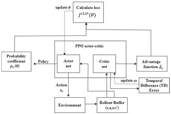
Figure 6.
Architecture of PPO Algorithm.
The policy network input comprises the joint states of the robotic arm and gripper status, together with the target object features derived from the YOLO detections. Both the Actor and Critic networks consisted of two fully connected layers, each with 64 hidden units, employing ReLU (Rectified Linear Unit) activation. The policy network Actor produces a continuous seven-dimensional action vector corresponding to the joint commands of the robotic arm. Since each component may assume both positive and negative values, a hyperbolic tangent (Tanh) activation is applied in the final layer to constrain the outputs within the valid action range.
6. Experiment and Results
6.1. Experimental Setup
In this study, we established a simulated physical environment using the PyBullet physics engine, integrated with the Gymnasium reinforcement learning library developed by OpenAI (San Francisco, CA, USA). This unified environment was employed for both the training and evaluation of the reinforcement learning neural networks. The robotic platform used in the simulation was a 7-DOF Franka Emika Panda industrial manipulator (Franka Emika GmbH, Dietersheim/Munich, Germany) equipped with a gripper. The arm has a mass of approximately 18 kg, a maximum payload capacity of 3 kg, an arm span of 0.85 m, and a repeatability of ±0.0001 m.
A 400 mm-wide conveyor was positioned 300 mm from the robot base, ensuring that the moving objects remained within the manipulator’s operational range. The simulation environment is illustrated in Figure 7. The simulated vision system comprised an RGB-D camera (Intel RealSense D435i, Intel Corporation, Santa Clara, CA, USA) with a resolution of 1280 × 960 pixels and a frame rate of 20 Hz, mounted above and outside the workspace to provide continuous monitoring of the conveyor. The captured images were subsequently used to train and deploy a YOLO-based object detection and classification model.
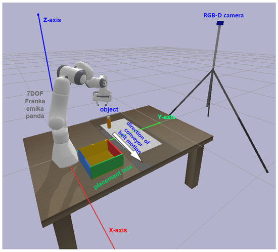
Figure 7.
Simulated environment. The white area indicates the reference region (compared with the semi-transparent conveyor belt) representing the feasible grasping workspace during testing.
All simulations were executed on a general-purpose laptop running Microsoft Windows 10, equipped with an Intel Core i7-11800H CPU @ 2.30 GHz, 32 GB RAM, and an NVIDIA GeForce RTX 3060 GPU. The programming platform was PyCharm 2022.2.3, and the software stack consisted of Python 3.11 and OpenCV 4.6.0, along with auxiliary libraries such as PyTorch 2.6.0 + CUDA 12.4, Stable-Baselines3 2.3.2, and TensorBoardX 2.6.2.2 for training the deep reinforcement learning models.
6.2. Training and Results of Detection YOLO
As shown in Figure 8, the experimental objects included various soda cans, paper cartons of different sizes, and other object types. In this study, we employed a YOLOv8-nano model pre-trained on the COCO dataset. However, since the COCO dataset contains numerous unrelated categories, the direct application of the pre-trained model may lead to misclassifications. To mitigate this issue, we adopted a transfer learning strategy [28,29] to accelerate convergence. Specifically, the model was initialized with COCO-trained weights provided by the YOLO authors, and a custom dataset of 190 original images was constructed, evenly distributed across four types of objects with a total of five labels. Because the dataset was relatively small, augmentation techniques were applied to generate two additional variants per source image, yielding a total of 570 images. A 50/20/30 split was used for training, validation and test sets. The following augmentations were applied to each source image to produce the augmented copies:
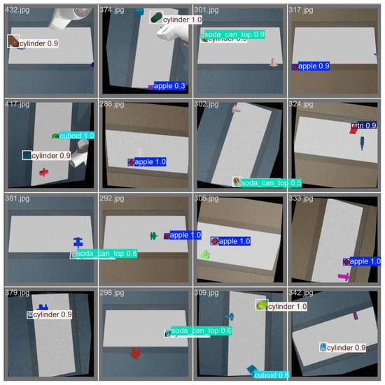
Figure 8.
Examples of augmented test images and YOLOv8n-OBB detection results.
50% probability of horizontal flip;
50% probability of vertical flip;
Equal probability of one of the following 90° rotations: none, clockwise, counter-clockwise, upside-down;
Random rotation between ±15°;
Random shear between ±15° horizontally and ±15° vertically;
Random exposure adjustment between ±10%;
Random Gaussian blur between 0 and 2 pixels;
Salt and pepper noise was applied to 1.25% of pixels.
Figure 8 illustrates examples of data augmentation applied during YOLO training, along with the corresponding detection results.
Figure 9 shows the training results of YOLOv8n and YOLOv8n-OBB after 28,500 iterations. The mAP50 and mAP50-95 (mean Average Precision) evaluation metrics are presented. It can be observed that under less stringent accuracy requirements, YOLOv8n-OBB only slightly outperforms YOLOv8n. However, as higher accuracy is required, the advantages of YOLOv8n-OBB become more apparent. Overall, YOLOv8n-OBB is more suitable than YOLOv8n for object detection tasks requiring higher precision.
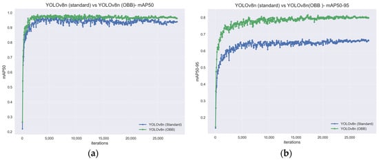
Figure 9.
Comparison of mAP between YOLOv8n and YOLOv8n OBB. (a) mAP50; (b) mAP50-95.
To evaluate the trained YOLOv8-nano model, several objects were randomly placed on the conveyor belt, and the detection results are illustrated in Figure 10b. The results demonstrate that YOLOv8-OBB successfully detects and classifies the target objects. Combined with the 3D coordinate calculation and refinement method presented in Section 3 (Figure 5), the system achieved robust detection, classification, and sub-centimeter-level localization accuracy for objects of interest.
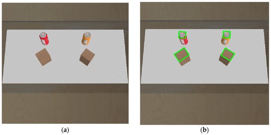
Figure 10.
(a) Conveyor belt area captured by the camera; (b) YOLOv8n OBB detection results, with the green lines indicating the detected object bounding boxes.
To provide a detailed evaluation of detection performance, we report per-class metrics on the test split, including precision, recall, mAP@0.5, and mAP@0.5:0.95. The results are summarized in Table 3, while precision–recall trade-offs and class-specific curves are illustrated in Figure 11. These results highlight differences across object categories and confirm that the trained YOLOv8n-OBB detector maintains consistently high accuracy across most classes.

Table 3.
Per-class detection performance of YOLOv8-OBB on the test set. Metrics include precision (P), recall (R), mAP@0.5, and mAP@0.5:0.95.

Figure 11.
Detection performance curves for YOLOv8n-OBB on the test set: (a) precision curves per class, (b) recall curves per class, and (c) precision–recall (PR) curves illustrating trade-offs across object categories.
For the cross-domain evaluation, we tested the model on a small real-world dataset of soda cans (https://universe.roboflow.com/radoslav-ivanov-rlxqq/coca-cola-products/dataset/3 (accessed on 1 October 2025)). The detection results are presented in Figure 12. The detection performance on the real-world soda can dataset is as follows:
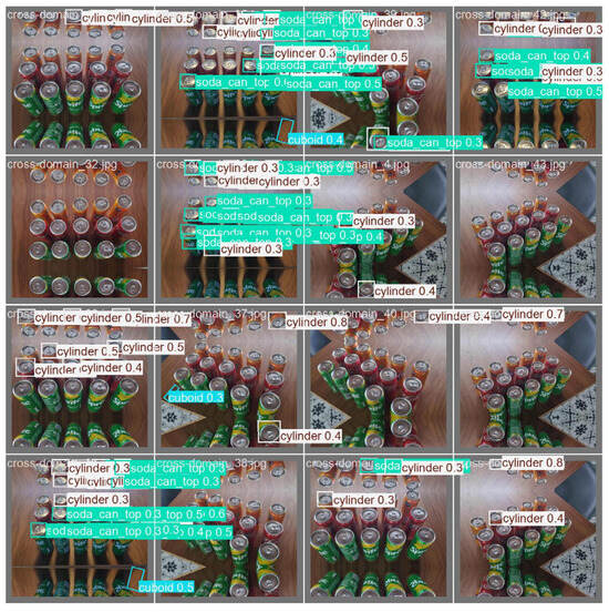
Figure 12.
Examples of detection results from a small cross-domain test. Empty subfigures indicate missed detections (no objects detected).
Class: soda_can_top.
Precision (P): 0.796.
Recall (R): 0.358.
Box Regression (mAP50): 0.574.
mAP50-95: 0.395.
Compared to the performance in simulation, real-world conditions such as lighting and the metallic texture of the objects led to a noticeable degradation in detection performance. Such factors, particularly the metallic sheen, are challenging to replicate accurately in the PyBullet simulation environment.
Although the mAP50 value is lower, the relatively high precision (P = 0.796) and recall (R = 0.358) indicate that the model performs better when the object’s metallic surface has a stronger sheen. The results also suggest that directly transferring a model trained on simulated data to real-world conditions can lead to detection failures due to differences in environmental factors such as lighting and surface material. However, despite these challenges, the overall mAP50 (0.574) and high precision (0.796) demonstrate that the trained model retains a certain level of generalization ability in suitable real-world conditions.
6.3. Curriculum Learning and Results
The PPO-based object grasping pipeline is illustrated in Figure 13. At the beginning of each episode, the environment was reset: the robotic arm was returned to its initial position, a target object was randomly placed on the conveyor, and an RGB-D camera captured the scene image. The YOLO-based detection and localization method described in Section 3 is applied. After refinement, the relative object poses were computed. The robotic joint states were integrated with this object state to form the input vector for the reinforcement learning agent. The PPO algorithm subsequently generates control actions to track the moving target. A grasp command was executed upon entering a feasible grasping zone without collisions. Following a successful grasp, the manipulator lifted the object vertically at a predefined distance, transported it to a designated placement position via inverse kinematics, and released it by opening the gripper, after which the trial outcome was recorded. A demonstration of the vision-based RL for robotic pick-and-place can be found in Supplementary Video S1.
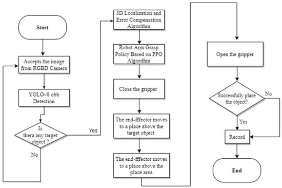
Figure 13.
Flowchart for robot arm grasping in this work.
If the target objects were randomized from the beginning of training, learning convergence would become prohibitively slow. To ensure a fair comparison among reinforcement learning algorithms, we implemented a curriculum learning strategy [30,31,32], which progressively increased the task difficulty. This approach allows algorithms to be benchmarked under lower-difficulty tasks before advancing to higher-difficulty conditions.
- Stage 1 Deterministic Environment—Lower Difficulty
In this stage, the environment was simplified to facilitate initial learning. The conveyor speed was fixed at 0.05 m/s, and the target object type was restricted to a cylindrical object. The PPO and three baseline algorithms (DDPG, SAC, and TD3) were trained under these conditions to assess their performance. The objective of the task was to guide the gripper to within 0.03 m of the target and complete a stable grasp without collisions.
Each algorithm was trained for approximately 24 million steps. As shown in Figure 14, the baseline algorithms fluctuated and peaked below 40%, whereas PPO exhibited markedly superior performance: after approximately 6 million steps, its success rate stabilized above 80%, with the best-trained model reaching 100%. (Hyperparameters, training durations, size and mass of objects in the simulation are provided in Table A1 and Table A2, Appendix A.) We selected the hyperparameters based on prior studies [7,33,34,35], In particular, the learning rate α was tested within the commonly used range of 0.00001 to 0.0003, with 0.0003 ultimately chosen as a safe and widely adopted initial value: smaller values led to very slow convergence, while larger values caused unstable policies. Other parameters followed standard PPO practice: the Adam optimizer, batch size of 256 (consistent with Stable-Baselines3 defaults for stable updates), discount factor γ = 0.99, GAE parameter λ = 0.95, and clipping factor ϵ = 0.2. These values are well-established in the literature and generally not varied extensively, as they provide a stable balance between exploration and convergence. Consequently, PPO was selected as the algorithm for subsequent higher-difficulty training.
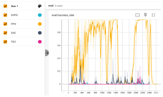
Figure 14.
Task success rate of PPO versus baseline algorithms during Stage 1 training. (X-axis: training steps, Y-axis: success rate; recorded via TensorBoardX).
- Stage 2 Randomized Environment—Higher Difficulty
After the PPO exhibited a stable performance in the deterministic stage, we transitioned to a more challenging randomized environment to simulate real-world variability. At the start of each episode, the speed of conveyor was randomly sampled from 0.03–0.22 m/s, and the target objects were randomly chosen from soda can or paper carton. For paper cartons, the yaw rotation angle ω relative to the conveyor surface was randomized, and their dimensions were perturbed within predefined ranges (length: 0.05–0.06 m, width: 0.03–0.045 m), subject to gripper constraints.
This randomization requires the agent to adapt to variations in object attributes and conveyor dynamics, thereby learning a more robust control strategy. The PPO, evaluated as the best-performing algorithm from Stage 1, was then selected to be trained under these conditions.
- Stage 3 Performance Bottleneck Diagnosis
In Stage 2, as shown in Figure 15, the success rate of PPO plateaued at approximately 50%. We hypothesize two limiting factors:
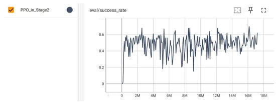
Figure 15.
Task success rate of PPO during training in Stage 2. (X-axis: training steps, Y-axis: success rate; recorded via TensorBoardX).
- (a)
- difficulty in maintaining stable pursuit of targets at higher conveyor speeds;
- (b)
- inability to reliably avoid collisions with sharp edges of cuboid objects.
To test these hypotheses, we conducted a diagnostic analysis of the converged Stage 2 model under controlled conditions. For each predefined conveyor speed interval, the object type was fixed, and the grasping success rates were measured across 100 randomized trials. the results are shown in the following Table 4.

Table 4.
Grasping success rates under varying conveyor speeds.
The results reveal that cylindrical soda cans are generally easier to manipulate, while carton boxes exhibited markedly lower success rates owing to orientation alignment requirements. For soda cans, grasping success remained around 80% for conveyor speeds up to 0.13 m/s but decreased sharply beyond this threshold. In contrast, for paper cartons, the performance dropped from 80% at low speeds (0.03–0.07 m/s) to ~50% in the mid-range (0.07–0.15 m/s), and becoming nearly infeasible beyond 0.15 m/s.
The decline in grasping success for rectangular cartons at speeds above 0.07 m/s can be attributed to their larger dimensions and rotation angles. Unlike cylindrical cans, which can be grasped symmetrically from multiple directions, cartons require alignment of the gripper with their longer side. At higher speeds or with larger rotation angles, the near edge of the carton is more likely to contact the gripper outside the predefined grasping zone. While such contact may be acceptable in practice, it is treated as a collision in the simulation, leading to lower success rates. Additional tests confirmed that when the carton rotation was restricted to 0–20°, the success rate became nearly comparable to that of soda cans. This suggests that limiting object rotation or slightly enlarging the pre-grasp workspace could partially mitigate failures. However, grasping objects with rotation angles remains inherently more challenging and requires further improvements in gripper design or end-effector strategies.
6.4. Ablation Experiments
To further verify the effectiveness of the designed reward function and the curriculum learning strategy, we conducted ablation experiments by gradually introducing different components into the training process. As a baseline (Base), we only retained the essential collision penalty and the final success reward. On this basis, additional components were incrementally added, including:
R_dist: Distance-based reward;
R_align: Pose alignment reward;
R_t_left: Remaining time bonus reward;
CL: Curriculum Learning strategy;
Each configuration was trained and evaluated over approximately 8.5 million timesteps, and the success rates were compared. The results are summarized in Figure 16.

Figure 16.
Verification of the effectiveness of reward functions and curriculum learning through ablation experiments (target: carton, speed: 0.05–0.07 m/s).
The results clearly indicate that when only the collision penalty and success reward are used (Base), the agent shows no effective learning, confirming that a minimalistic reward without informative shaping signals fails to guide the policy. Introducing the distance-based reward leads to the emergence of basic learning ability, while the subsequent addition of pose alignment reward and remaining time bonus reward further improves convergence speed and final performance. Finally, when the curriculum learning strategy is integrated, the learning efficiency improves significantly, and the agent achieves the highest success rate. According to the results of the ablation experiments, at lower conveyor speeds (e.g., 0.05–0.07 m/s in the tests), the success rate can reach up to nearly 90%, but subsequent growth was weak. This finding provides insights for future work, suggesting that the reward function may still have potential for further optimization.
Considering the potential vibrations that may occur on a real conveyor belt, we conducted ablation studies on the target object’s XYZ positions in simulation. The vibration-free condition was used as the baseline. We then examined how different vibration amplitudes, modeled as sinusoidal errors with a frequency of 2 Hz applied to the object’s X, Y, and Z axes over time, affected the grasping success rate. Additionally, we evaluated the success rate under partial occlusion of the object, as well as when the target was replaced from a soda can to a triangular prism and an apple. The results are summarized in Table 5.

Table 5.
Success rate under different vibration conditions, occlusion, and object types.
It can be observed from the simulation results that when the vibration amplitude along the Z-axis exceeds 0.01 m, the grasping success rate begins to decline significantly, whereas displacements caused by vibrations along the X and Y axes have a relatively smaller impact. Furthermore, when the object is more than 50% occluded, the success rate drops drastically. These findings suggest that in practical conveyor scenarios, it is crucial to minimize Z-axis vibrations of the objects while maintaining normal conveying capability, and to reduce significant occlusions between the camera and the target.
As a possible improvement, a trajectory analysis function could be incorporated to temporarily predict the target position when it disappears from the camera’s field of view. Alternatively, recurrent neural network architectures such as LSTM (Long Short-Term Memory) could be employed to predict the target trajectory.
To further evaluate the generalization ability of the proposed model, we replaced the target object with a triangular prism, which requires precise alignment, and an apple, which does not. In both cases, the grasping task could still be completed with only minor performance degradation. Considering that most products are identical or highly similar, this demonstrates the robustness and general applicability of our approach.
7. Discussion and Conclusions
Although the simulated experiments produced encouraging results, it is crucial to acknowledge their limitations. Below we first place our work in context with closely related studies, then provide a concise statement of scope and limitations, followed by a detailed account of specific limitations and a concluding outlook.
7.1. Comparative Analysis with Related Work
Previous research on reinforcement-learning-based robotic grasping has largely focused on static or quasi-static scenarios. For example, Chen et al. [7] combined SAC with YOLOv3 to grasp stationary objects and reported successful Sim-to-Real transfer under carefully controlled conditions. Our work extends this line of research to dynamic conveyor settings; however, the absence of physical hardware at the current stage precluded us from conducting Sim-to-Real experiments.
Wu et al. [4] investigated pose estimation with Dense Fusion [36] followed by reinforcement-learning-based grasping. Their research objective is close to ours in that both approaches employ RL for grasp execution. While Dense Fusion can provide more accurate 6D pose estimation, it does not inherently classify object types, which limits its applicability when category-level recognition is required for advanced sorting or class-aware grasping. In contrast, our method leverages YOLOv8n-OBB, which simultaneously performs object detection and oriented bounding box estimation. This combination allows recognition and approximate pose estimation for simple objects moving on a conveyor, offering a practical balance between detection accuracy and task-level utility.
Interestingly, Wu et al. also validated their approach on a physical robot arm, replicating the performance of prior algorithms for dynamic grasping. Despite methodological differences, most studies, including ours, report comparable success rates of around 80% in simulation when object speeds are in the range of 0.03–0.05 m/s. However, reaching near-perfect success remains elusive, suggesting that this task involves unresolved challenges that warrant further in-depth investigation.
7.2. Limitations and Scope
This study should be interpreted as a carefully measured simulation framework, not as direct evidence of an immediately deployable industrial system. The main constraints are (1) the use of PyBullet without photorealistic rendering, (2) omission of physical actuation and control-loop delays in latency estimates, and (3) simplified placement does not reflect the real industrial scene. Within this scope, the contribution of the present work lies in establishing a controlled simulation framework that demonstrates the feasibility of combining vision-based detection (YOLOv8n-OBB) with reinforcement learning (PPO) for grasping objects moving on a conveyor.
7.3. Detailed Limitations
First, simulation realism (lighting and rendering): PyBullet lacks photorealistic illumination and complex sensor artifacts, which limits the evaluation of vision robustness under varying lighting conditions, reflections, and sensor noise. To validate perception performance in real-world industrial scenarios, transitioning to a photorealistic renderer (e.g., Isaac Sim) or collecting real imagery will be necessary.
Second, timing and actuation delays: The reported computational latency (~90 ms total: YOLOv8n-OBB ~35 ms for preprocessing and inference, PPO ~2 ms for decision-making, plus overheads) reflects software-side delays only. Actuator dynamics, control-loop jitter, communication latency, and gripper mechanical response were not modeled. These physical delays would increase end-to-end latency and may reduce the effective conveyor speed achievable in practice.
Third, placement and environment complexity: The placement stage relied on inverse kinematics with pre-defined path points and did not incorporate obstacle detection/avoidance or multi-object interactions. This simplification limits applicability in cluttered scenes and for tasks requiring dynamic re-planning.
Fourth, robustness to occlusion and prolonged visual loss: While ablation tests included short occlusions and minor vibrations, extended occlusions or sustained sensor dropouts were not addressed. Practical deployment will require trajectory prediction, recurrent (temporal) models (e.g., LSTM), and sensor-fusion strategies to recover from or anticipate temporary perception loss.
7.4. Conclusions and Future Work
Within the defined scope, this work establishes a simulation framework that demonstrates the feasibility of using a vision-guided PPO policy to grasp objects moving on a conveyor, in combination with an oriented-bounding-box detector, achieving a ≥80% success rate at conveyor speeds of 0.03–0.07 m/s. Future work will focus on: (1) photorealistic simulation and domain-randomized training for Sim-to-Real transfer, (2) modeling and measurement of physical actuation and control-loop delays, (3) integration of obstacle-aware placement and dynamic motion planning, and (4) enhanced temporal prediction and sensor-fusion methods to improve robustness. These steps are intended to progressively bridge the gap from a controlled simulation environment toward practical industrial deployment
Supplementary Materials
The following supporting information can be downloaded from: https://www.mdpi.com/article/10.3390/machines13100973/s1. Video S1: Vision-Based RL for Robotic Pick-and-Place with Moving Objects on a Conveyor.
Author Contributions
Conceptualization, Y.C. and X.X.; methodology, Y.C. with input from Y.Z. and X.X.; software, Y.C. and. Y.Z.; validation, Y.C., X.X., Y.Z.; formal analysis, Y.C.; investigation, Y.C.; resources, Y.C.; data curation, Y.Z.; writing—original draft preparation, Y.C.; writing—review and editing, all authors; visualization, Y.C. and X.X.; supervision, Y.C.; project administration, Y.C.; funding acquisition, Y.C. All authors have read and agreed to the published version of the manuscript.
Funding
This research was funded by the China Scholarship Council (CSC), grant number No. 202108090230.
Data Availability Statement
Data are contained within the article.
Acknowledgments
The authors would like to thank the anonymous reviewers for their insightful suggestions and the editorial team for their guidance and support, which have been instrumental in improving this paper. The financial support from the China Scholarship Council (CSC) is also gratefully acknowledged. It should be noted that all opinions, findings, conclusions, and recommendations presented in this paper are those of the authors and do not necessarily represent the views of the sponsor.
Conflicts of Interest
The authors declare no conflicts of interest.
Abbreviations
The following abbreviations are used in this manuscript:
| RL | Reinforcement learning |
| YOLO | Algorithm You Only Look Once Model |
| PPO | Algorithm Proximal policy optimization |
| DDPG | Algorithm Deep Deterministic Policy Gradient |
| TD3 | Algorithm Twin Delayed Deep Deterministic policy gradient algorithm |
| SAC | Algorithm Soft Actor-Critic |
Appendix A

Table A1.
Hyperparameters and training time in Stage 1.
Table A1.
Hyperparameters and training time in Stage 1.
| Hyperparameter | PPO | DDPG | TD3 | SAC |
| policy | MlpPolicy | MlpPolicy | MlpPolicy | MlpPolicy |
| learning rate α | 0.0003 | 0.0003 | 0.0003 | 0.0003 |
| optimizer | Adam | Adam | Adam | Adam |
| batch size | 256 | 256 | 256 | 256 |
| discount factor γ | 0.99 | 0.99 | 0.99 | 0.99 |
| device | cpu | cpu | cpu | cpu |
| n_steps | 2048 | - | - | - |
| n_epochs | 10 | - | - | - |
| buffer_size | - | 1 × 10⁶ | 1 × 10⁶ | 1 × 10⁶ |
| training time | 3 h 39 min | 9 h 15 min | 8 h 51 min | 9 h 21 min |

Table A2.
The size and mass of objects in the simulation environment.
Table A2.
The size and mass of objects in the simulation environment.
| Object | Size (m) | Mass (kg) |
| soda can | 0.045 × 0.045 × 0.107 | 0.3 |
| carton | 0.055 × 0.04 × 0.10 | 0.45 |
| apple | 0.046 × 0.046 × 0.075 | 0.2 |
| triangular prism | 0.05 × 0.05 × 0.12 | 0.6 |
References
- Zhao, Z.-Q.; Zheng, P.; Xu, S.; Wu, X. Object Detection with Deep Learning: A Review. IEEE Trans. Neural Netw. Learn. Syst. 2018, 30, 3212–3232. [Google Scholar] [CrossRef]
- Wu, X.; Sahoo, D.; Hoi, S.C. Recent Advances in Deep Learning for Object Detection. Neurocomputing 2020, 396, 39–64. [Google Scholar] [CrossRef]
- Akinola, I.; Xu, J.; Song, S.; Allen, P.K. Dynamic Grasping with Reachability and Motion Awareness. In Proceedings of the 2021 IEEE/RSJ International Conference on Intelligent Robots and Systems (IROS), Prague, Czech Republic, 27 September–1 October 2021; IEEE: Prague, Czech Republic, 2021; pp. 9422–9429. [Google Scholar]
- Wu, T.; Zhong, F.; Geng, Y.; Wang, H.; Zhu, Y.; Wang, Y.; Dong, H. Grasparl: Dynamic Grasping via Adversarial Reinforcement Learning. arXiv 2022, arXiv:2203.02119. [Google Scholar] [CrossRef]
- Huang, B.; Yu, J.; Jain, S. EARL: Eye-on-Hand Reinforcement Learner for Dynamic Grasping with Active Pose Estimation. In Proceedings of the 2023 IEEE/RSJ International Conference on Intelligent Robots and Systems (IROS), Detroit, MI, USA, 1–5 October 2023; pp. 2963–2970. [Google Scholar]
- Imtiaz, M.B.; Qiao, Y.; Lee, B. PolyDexFrame: Deep Reinforcement Learning-Based Pick-and-Place of Objects in Clutter. Machines 2024, 12, 547. [Google Scholar] [CrossRef]
- Chen, Y.-L.; Cai, Y.-R.; Cheng, M.-Y. Vision-Based Robotic Object Grasping—A Deep Reinforcement Learning Approach. Machines 2023, 11, 275. [Google Scholar] [CrossRef]
- Pane, Y.P.; Nageshrao, S.P.; Kober, J.; Babuška, R. Reinforcement Learning Based Compensation Methods for Robot Manipulators. Eng. Appl. Artif. Intell. 2019, 78, 236–247. [Google Scholar] [CrossRef]
- Zamora, I.; Lopez, N.G.; Vilches, V.M.; Cordero, A.H. Extending the OpenAI Gym for Robotics: A Toolkit for Reinforcement Learning Using ROS and Gazebo 2017. arXiv 2017, arXiv:1608.05742. [Google Scholar]
- Kaup, M.; Wolff, C.; Hwang, H.; Mayer, J.; Bruni, E. A Review of Nine Physics Engines for Reinforcement Learning Research 2024. arXiv 2024, arXiv:2407.08590. [Google Scholar]
- Panerati, J.; Zheng, H.; Zhou, S.; Xu, J.; Prorok, A.; Schoellig, A.P. Learning to Fly—A Gym Environment with PyBullet Physics for Reinforcement Learning of Multi-Agent Quadcopter Control. In Proceedings of the 2021 IEEE/RSJ International Conference on Intelligent Robots and Systems (IROS), Prague, Czech Republic, 27 September–1 October 2021; IEEE: Prague, Czech Republic, 2021; pp. 7512–7519. [Google Scholar] [CrossRef]
- Jiang, P.; Ergu, D.; Liu, F.; Cai, Y.; Ma, B. A Review of Yolo Algorithm Developments. Procedia Comput. Sci. 2022, 199, 1066–1073. [Google Scholar] [CrossRef]
- Diwan, T.; Anirudh, G.; Tembhurne, J.V. Object Detection Using YOLO: Challenges, Architectural Successors, Datasets and Applications. Multimed. Tools Appl. 2023, 82, 9243–9275. [Google Scholar] [CrossRef]
- Hussain, M. YOLO-v1 to YOLO-v8, the Rise of YOLO and Its Complementary Nature toward Digital Manufacturing and Industrial Defect Detection. Machines 2023, 11, 677. [Google Scholar] [CrossRef]
- Schulman, J.; Wolski, F.; Dhariwal, P.; Radford, A.; Klimov, O. Proximal Policy Optimization Algorithms 2017. arXiv 2017, arXiv:1707.06347. [Google Scholar]
- Haarnoja, T.; Zhou, A.; Abbeel, P.; Levine, S. Soft Actor-Critic: Off-Policy Maximum Entropy Deep Reinforcement Learning with a Stochastic Actor. In Proceedings of the International Conference on Machine Learning, Stockholm, Sweden, 10–15 July 2018; PMLR: Cambridge, MA, USA, 2018; pp. 1861–1870. [Google Scholar]
- Fujimoto, S.; Hoof, H.; Meger, D. Addressing Function Approximation Error in Actor-Critic Methods. In Proceedings of the International Conference on Machine Learning, Stockholm, Sweden, 10–15 July 2018; PMLR: Cambridge, MA, USA, 2018; pp. 1587–1596. [Google Scholar]
- Lillicrap, T.P.; Hunt, J.J.; Pritzel, A.; Heess, N.; Erez, T.; Tassa, Y.; Silver, D.; Wierstra, D. Continuous Control with Deep Reinforcement Learning. arXiv 2019, arXiv:1509.02971. [Google Scholar]
- Towers, M.; Kwiatkowski, A.; Terry, J.; Balis, J.U.; Cola, G.D.; Deleu, T.; Goulão, M.; Kallinteris, A.; Krimmel, M.; KG, A.; et al. Gymnasium: A Standard Interface for Reinforcement Learning Environments. arXiv 2024, arXiv:2407.17032. [Google Scholar] [CrossRef]
- Yang, X.; Ji, Z.; Wu, J.; Lai, Y.-K. An Open-Source Multi-Goal Reinforcement Learning Environment for Robotic Manipulation with Pybullet. In Proceedings of the Annual Conference Towards Autonomous Robotic Systems, London, UK, 8–10 September 2021; Springer: Berlin/Heidelberg, Germany, 2021; pp. 14–24. [Google Scholar]
- Xie, X.; Cheng, G.; Wang, J.; Yao, X.; Han, J. Oriented R-CNN for Object Detection. In Proceedings of the IEEE/CVF International Conference on Computer Vision, Montreal, BC, Canada, 11–17 October 2021; pp. 3520–3529. [Google Scholar]
- Han, J.; Ding, J.; Li, J.; Xia, G.-S. Align Deep Features for Oriented Object Detection. IEEE Trans. Geosci. Remote Sens. 2021, 60, 1–11. [Google Scholar] [CrossRef]
- Wen, L.; Cheng, Y.; Fang, Y.; Li, X. A Comprehensive Survey of Oriented Object Detection in Remote Sensing Images. Expert Syst. Appl. 2023, 224, 119960. [Google Scholar] [CrossRef]
- Sohan, M.; Sai Ram, T.; Rami Reddy, C.V. A Review on Yolov8 and Its Advancements. In Proceedings of the International Conference on Data Intelligence and Cognitive Informatics, Tirunelveli, India, 18–20 November 2024; Springer: Berlin/Heidelberg, Germany, 2024; pp. 529–545. [Google Scholar]
- Lou, H.; Duan, X.; Guo, J.; Liu, H.; Gu, J.; Bi, L.; Chen, H. DC-YOLOv8: Small-Size Object Detection Algorithm Based on Camera Sensor. Electronics 2023, 12, 2323. [Google Scholar] [CrossRef]
- Wang, X.; Gao, H.; Jia, Z.; Li, Z. BL-YOLOv8: An Improved Road Defect Detection Model Based on YOLOv8. Sensors 2023, 23, 8361. [Google Scholar] [CrossRef] [PubMed]
- Lin, T.-Y.; Dollár, P.; Girshick, R.; He, K.; Hariharan, B.; Belongie, S. Feature Pyramid Networks for Object Detection. In Proceedings of the IEEE Conference on Computer Vision and Pattern Recognition, Honolulu, HI, USA, 21–26 July 2017; pp. 2117–2125. [Google Scholar]
- Pan, S.J.; Yang, Q. A Survey on Transfer Learning. IEEE Trans. Knowl. Data Eng. 2009, 22, 1345–1359. [Google Scholar] [CrossRef]
- Panigrahi, S.; Nanda, A.; Swarnkar, T. A Survey on Transfer Learning. In Intelligent and Cloud Computing: Proceedings of ICICC 2019; Springer: Berlin/Heidelberg, Germany, 2020; Volume 1, pp. 781–789. [Google Scholar]
- Bengio, Y.; Louradour, J.; Collobert, R.; Weston, J. Curriculum Learning. In Proceedings of the 26th Annual International Conference on Machine Learning, Montreal, QC, Canada, 14–18 June 2009; pp. 41–48. [Google Scholar]
- Wang, X.; Chen, Y.; Zhu, W. A Survey on Curriculum Learning. IEEE Trans. Pattern Anal. Mach. Intell. 2021, 44, 4555–4576. [Google Scholar] [CrossRef] [PubMed]
- Graves, A.; Bellemare, M.G.; Menick, J.; Munos, R.; Kavukcuoglu, K. Automated Curriculum Learning for Neural Networks. In Proceedings of the International Conference on Machine Learning, Sydney, Australia, 6–11 August 2017; PMLR: Cambridge, MA, USA, 2017; pp. 1311–1320. [Google Scholar]
- Tang, W.; Cheng, C.; Ai, H.; Chen, L. Dual-Arm Robot Trajectory Planning Based on Deep Reinforcement Learning under Complex Environment. Micromachines 2022, 13, 564. [Google Scholar] [CrossRef] [PubMed]
- Iriondo, A.; Lazkano, E.; Susperregi, L.; Urain, J.; Fernandez, A.; Molina, J. Pick and Place Operations in Logistics Using a Mobile Manipulator Controlled with Deep Reinforcement Learning. Appl. Sci. 2019, 9, 348. [Google Scholar] [CrossRef]
- Tapia Sal Paz, B.; Sorrosal, G.; Mancisidor, A.; Calleja, C.; Cabanes, I. Reinforcement Learning-Based Control for Robotic Flexible Element Disassembly. Mathematics 2025, 13, 1120. [Google Scholar] [CrossRef]
- Wang, C.; Xu, D.; Zhu, Y.; Martín-Martín, R.; Lu, C.; Fei-Fei, L.; Savarese, S. Densefusion: 6d Object Pose Estimation by Iterative Dense Fusion. In Proceedings of the IEEE Conference on Computer Vision and Pattern Recognition, Long Beach, CA, USA, 16–20 June 2019; pp. 3343–3352. [Google Scholar]
Disclaimer/Publisher’s Note: The statements, opinions and data contained in all publications are solely those of the individual author(s) and contributor(s) and not of MDPI and/or the editor(s). MDPI and/or the editor(s) disclaim responsibility for any injury to people or property resulting from any ideas, methods, instructions or products referred to in the content. |
© 2025 by the authors. Licensee MDPI, Basel, Switzerland. This article is an open access article distributed under the terms and conditions of the Creative Commons Attribution (CC BY) license (https://creativecommons.org/licenses/by/4.0/).