1. Introduction
With the acceleration of urbanization and the escalating demand for low-carbon transport, maglev systems have emerged as a pivotal technology for addressing urban congestion and regional connectivity, owing to their advantages of low noise, contactless operation, and robust gradient-climbing capability [
1]. Currently, typical maglev transport systems comprise four categories: electromagnetic suspension (EMS), electric suspension (EDS), high-temperature superconducting pinning suspension (HTSS), and permanent magnet levitation (PML) [
2,
3,
4,
5]. Among these, PML achieves levitation through the repulsive force between permanent magnets, eliminating the need for an external power supply. This ‘zero-power levitation’ characteristic confers unique advantages in energy efficiency and operational reliability [
5,
6].
Halbach arrays, the core technology in PML systems, have found applications in numerous fields since their invention in 1979, including in maglev trains and magnetic bearings. By orienting the permanent magnets in a specific pattern, the Halbach array can significantly strengthen the magnetic field on one side while reducing it to near zero on the other, thereby greatly improving the levitation force [
7]. Extensive research has been conducted on the application of Halbach arrays in maglev trains, focusing on the magnetic field distribution and force characteristics of these arrays [
8,
9]. Studies have also been carried out to optimize the dimensions and magnetization directions of Halbach-type permanent magnets for enhanced magnetic performance [
10,
11]. However, most current optimization efforts are primarily focused on increasing the levitation force of the system, while paying scant attention to the issue of lateral force stability.
The Xingguo permanent magnet levitation (PML) test line (
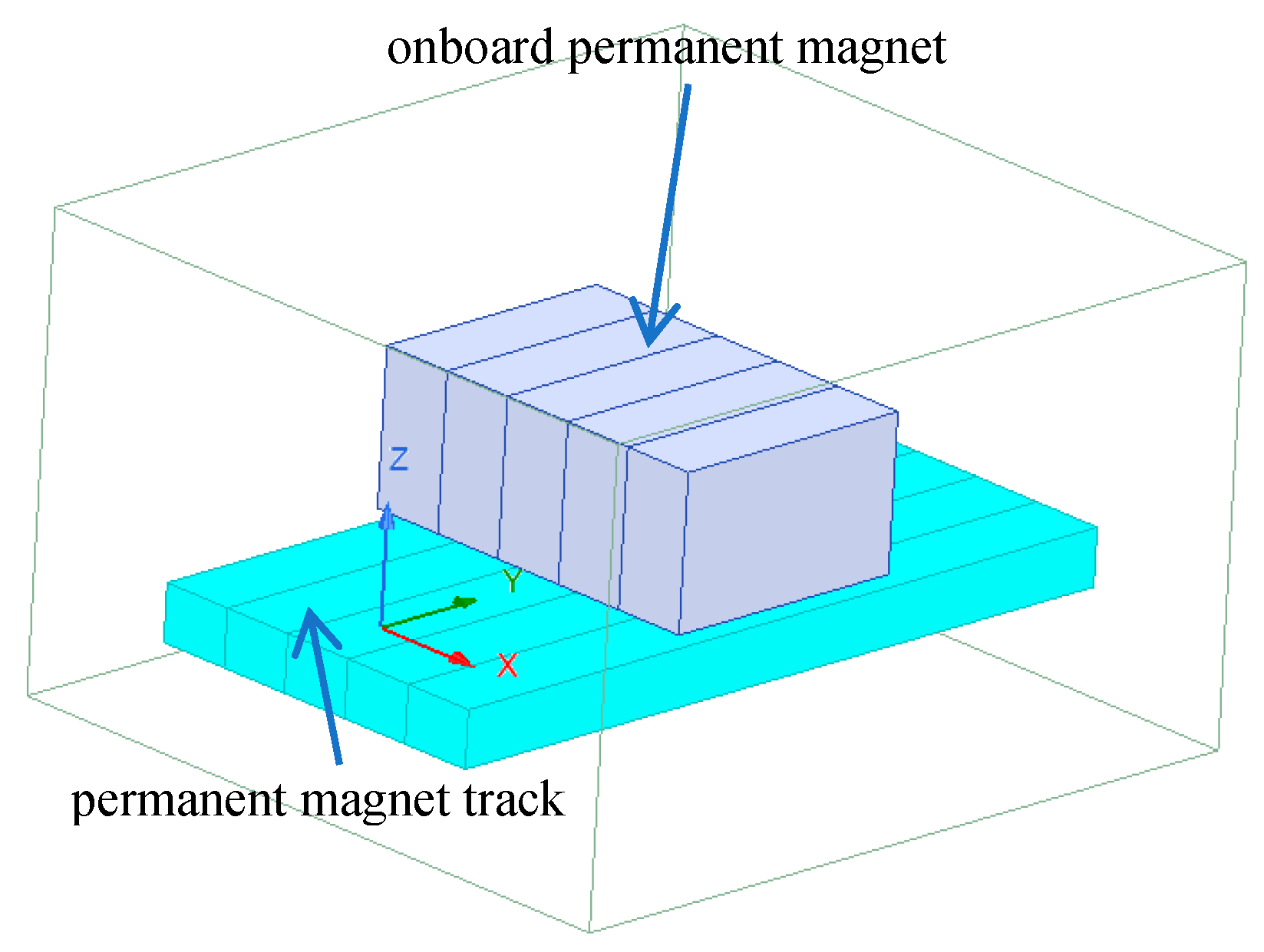
Figure 1), spearheaded by Jiangxi University of Science and Technology and commissioned in 2022 in Xingguo County, Jiangxi Province, spans a total length of 0.8 km. It represents China’s first engineering test line for rare-earth permanent magnet levitation rail transit. The system utilizes Halbach arrays composed of both onboard and track-mounted permanent magnets to achieve “zero-power” levitation.
Current research on the dynamics of PML systems remains at a preliminary stage. Shi et al. [
12,
13] established a vehicle-bridge coupling model for the PML system, laying a foundation for dynamic analysis. Kuang et al. [
14] analyzed the vibration response of the PML train’s bogie and car body, finding that the lateral vibration acceleration of the car body exceeds its vertical acceleration at the same speed. This phenomenon is primarily attributed to the lateral negative stiffness of the Halbach array, which compromises system stability and has become a critical bottleneck hindering the engineering advancement of PML technology. Current research on improving the lateral stability of PML trains mainly focuses on electromagnetic levitation control. For instance, Hu et al. [
15] introduced electromagnetic guidance to regulate the dynamic lateral displacement of magnets, thereby reducing coupled vibrations. Guo et al. [
16] proposed a hybrid permanent magnet and electromagnetic model, utilizing electromagnetic control to mitigate system vibrations and achieve motion decoupling, offering insights for vehicle vibration suppression. Liu et al. [
17] explored optimizing vehicle vibration performance by leveraging interactions and combinations of structure, device, and control. However, employing electromagnetic control introduces complex control systems and increases construction costs.
In the Xingguo PML, each bogie levitates through four discrete levitation points. Among them, the suspension points symmetrically arranged on the left and right sides of the bogie form a basic suspension unit. This unit is similar to the wheelset in wheel–rail traffic in structure, and is the core of bearing and transmitting magnetic force. In this paper, the levitation unit formed by the left and right two-point coupling is defined as “Magnetic Wheels”. Consequently, each bogie essentially achieves stable levitation through the collective interaction of two sets of dual “Magnetic Wheels”. Current research predominantly focuses on theoretical analysis and simulation verification of single-point levitation characteristics [
18], overlooking the coupling effects between Magnetic Wheelset in practical operation. Importantly, different mounting types—with parameters such as inclination angle and center distance—directly affect the balance between levitation and lateral forces, thereby critically determining the vehicle’s dynamic performance. Therefore, investigating how a magnetic pair mounting type influences force characteristics and identifying optimal structures that achieve a balance between levitation and lateral forces are essential for enhancing the system’s operational stability.
This paper makes its primary contributions in two key areas:
- (1)
This study first employs the CV to evaluate force stability. As a dimensionless metric, the CV eliminates the influence of physical dimensions and comprehensively reflects the fluctuation degree of forces. A smaller CV indicates lower force variations, which corresponds to better operational stability of the vehicle. Taking the existing dual-levitator installation configuration of the Xingguo PML system as the baseline case, the CV values of its levitation force and lateral force are used as benchmarks. Cases satisfying the condition that both their levitation and lateral force CVs are smaller than those of the baseline are regarded as qualified. This approach effectively screens out cases with higher force stability during vehicle operation.
- (2)
Since the CV only reflects the fluctuation amplitude of data and not their absolute magnitudes, a mean force threshold is introduced to prevent cases with sufficient stability but inadequate levitation force or excessive lateral force. Using the mean levitation and lateral forces of the baseline case as references, this study sets threshold values to eliminate configurations with insufficient levitation force or overly large lateral force. The dual-constraint method—combining the CV and mean force thresholds—enables rapid identification of the optimal case. This strategy provides a valuable reference for structural design and performance optimization of PML transportation systems.
The structure of this paper is as follows:
Section 2 introduces the levitation characteristics of a single point in the permanent magnet levitation system, establishes theoretical and finite element models, and validates model accuracy through experiments. Based on the single-point levitation;
Section 3 designs five mounting type of “Magnetic Wheelsets” and analyzes their influence on levitation and lateral forces;
Section 4 describes the constraint method combining the coefficient of variation and mean force thresholds to screen the optimal case;
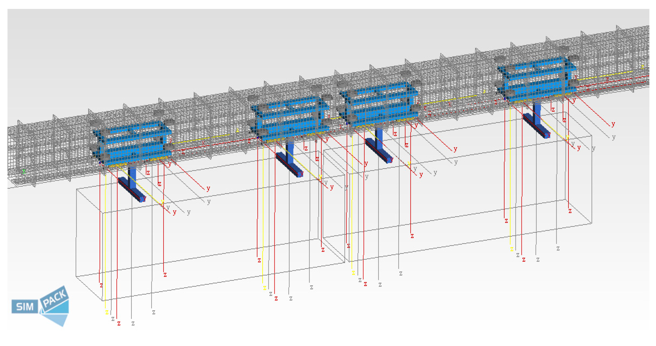
Section 5 validates the case selected by the proposed constraint method through dynamic simulations; and
Section 6 concludes the primary work of this research.
3. Magnetic Wheelset Characteristics
In the preceding section, theoretical calculations and simulation analyses of the single-point permanent magnet levitation system have clearly revealed the nonlinear variation patterns of levitation force and lateral force, providing crucial insights into the magnetic characteristics of permanent magnet levitation. Each bogie of the Xingguo Line permanent magnet levitation transport system achieves levitation through the interaction of two sets of ‘Magnetic Wheelset’. When these magnetic pairs adopt a different mounting type, the resulting spatial magnetic field patterns also differ, consequently altering the overall levitation performance of the magnetic pair.
Therefore, this paper employs the validated single-point finite element model to construct a ‘Magnetic Wheelset’ model and investigates the characteristics of magnetic pairs under various mounting types.
As shown in
Figure 6, several different mounting types of Magnetic Wheelset are illustrated, including ‘Aligned mounting’, ‘X-type mounting’, ‘different center distances mounting’, ‘Double V-type mounting’, and ‘Single V-type mounting’. When the vehicle-mounted magnet and the permanent magnet track have the same center distance and are installed horizontally, this configuration is referred to as ‘Aligned mounting’. As shown in
Figure 7a, this mounting type is currently used in the Xingguo Line permanent magnet levitation transport systems. Its magnetic force characteristics will serve as the baseline reference model, designated as case 1. When the center distance between the on-board magnet and the permanent magnet track is the same and a certain angle is formed in the horizontal plane, the installed form is ‘X-type mounting’, as shown in
Figure 7b, which is defined hereinafter as case 2. As shown in
Figure 7c, when the vehicle magnet and the permanent magnet track are aligned in parallel, but both form a certain angle A with the horizontal plane, the installed form is ‘Double V-type mounting’, which is hereinafter defined as case 3. When the center distance between the vehicle magnet and the track magnet is different, the installed form is defined as ‘different center distances mounting’, as shown in
Figure 7d, hereinafter defined as working case 4. As shown in
Figure 7e, when the track magnet is horizontally installed while the vehicle-mounted magnet is installed at a certain angle relative to the track magnet, the resulting configuration is termed the Single V-type mounting, which will be defined as case 5. The angles α, β, and γ, corresponding to cases 2, 3, and 5, can be either positive or negative, while the center distance in case 4 can be either increased or decreased. The study revealed that the magnetic pair characteristics remain identical regardless of whether angle α is positive or negative, or whether the center distance is increased or decreased. Therefore, this paper will only analyze the cases illustrated in
Figure 6.
As shown in
Figure 6, except for Case 1, each installation form corresponds to specific variable parameters.
Table 2 lists the parameter values for all cases according to the operational requirements of the permanent magnet levitation transportation system. Each case includes six parameters. To clearly identify the cases associated with different mounting type and parameters, the following naming convention is adopted: Case 2 with a parameter range of 5° to 30° corresponds to Cases 2-1 through 2-6; Case 3 with 4 mm to 24 mm corresponds to Cases 3-1 through 3-6; Case 4 with 2.5° to 15° corresponds to Cases 4-1 through 4-6; and Case 5 with the same 2.5° to 15° range corresponds to Cases 5-1 through 5-6. Simulations were performed using Ansoft Maxwell to evaluate the levitation and lateral forces across levitation heights of 5–30 mm and lateral displacements of −15 to 15 mm, with a 1 mm step size, yielding 750 data sets per case.
To analyze the levitation characteristics under different mounting types, comparative analyses were conducted between Case 2-2, Case 3-2, Case 4-2, Case 5-2, and the baseline, Case 1, examining both single-point and Magnetic Wheelset scenarios for levitation force and lateral force, as illustrated in
Figure 7.
As shown in
Figure 7a,b, the levitation forces and lateral forces corresponding to the Magnetic Wheelset under Case 2-2 and Case 1 are presented. It can be observed that under Case 2, the levitation and lateral forces of the left and right individual points of the Magnetic Wheelset are identical. Compared with Case 1, the variation trends of both the levitation and lateral forces remain similar, but their magnitudes decrease.
This reduction is primarily attributed to the fact that, in this mounting type, a certain angle is formed between the onboard magnet and the permanent magnet track in the horizontal plane, as illustrated in
Figure 6b. As a result, the effective opposing area between them is reduced relative to Case 1, leading to a decrease in the levitation force. Consequently, the lateral force also decreases.
As shown in
Figure 7c,d, the levitation and lateral forces corresponding to the Magnetic Wheelset formed by the left and right points under Case 3-2 and Case 1 are presented. The results indicate that under the mounting type of Case 3, the variation trends of both the levitation and lateral forces differ between the left and right points. At a lateral displacement of zero, the levitation forces on the left and right sides are equal, while the lateral forces are equal in magnitude but opposite in direction.
As the Magnetic Wheelset undergoes a leftward lateral displacement, the levitation force at the right point increases gradually, while its lateral force initially decreases before increasing. In contrast, the levitation force at the left point decreases rapidly, and its lateral force shows a gradual increase. This phenomenon occurs primarily due to the mounting type in Case 3, where an angle is formed between the onboard magnets and the permanent magnet track relative to the horizontal plane, as illustrated in
Figure 6c. When a leftward lateral displacement occurs, the onboard permanent magnet at the right point moves closer to the track, while the magnet at the left point moves away. Consequently, the levitation force at the right point increases slowly, whereas that at the left point decreases rapidly. Since the lateral forces at the left and right points are opposite in direction at zero lateral displacement, a leftward shift causes the lateral force on the left side to decrease gradually to zero and then increase, while the lateral force on the right side increases continuously.
However, compared to Case 1, both the levitation and lateral forces of the Magnetic Wheelset in Case 3-2 are generally reduced. This overall reduction is mainly attributed to the inclination angle, which generates a horizontal component of the levitation force, thereby reducing the effective vertical levitation force. This horizontal component is always equal in magnitude and opposite in direction on the two sides, resulting in no net effect on the overall lateral force of the Magnetic Wheelset. Nevertheless, the decrease in levitation force ultimately leads to a reduction in the lateral force.
As shown in
Figure 7e,f, the levitation and lateral forces of the Magnetic Wheelset formed by the left and right points under Case 4-2 and Case 1 are presented. The results indicate that under the mounting type of Case 4, the levitation and lateral forces differ between the left and right points. At zero lateral displacement, the levitation forces on both sides are equal. The lateral forces are equal in magnitude but opposite in direction, resulting in a net lateral force of zero for the Magnetic Wheelset.
When lateral displacement occurs, and as it increases from 0 to 4 mm, the levitation force at the left point shows an increasing trend, only beginning to decrease gradually after the displacement exceeds 4 mm. In contrast, the levitation force at the right point decreases continuously, and at a faster rate than that at the left point. The lateral force at the left point decreases to zero as the displacement increases from 0 to 4 mm, and then gradually increases as the displacement increases further to 15 mm. Meanwhile, the lateral force at the right point increases monotonically throughout the process.
This behavior is primarily attributed to the specific mounting in Case 4, where the center distance between the onboard magnets is greater than that of the permanent magnet track. This means that even at zero nominal lateral displacement, the left point is effectively pre-displaced to the left and the right point to the right, as illustrated in
Figure 6d. Consequently, when an additional rightward lateral displacement is applied, the right point experiences further displacement relative to the track, leading to a rapid decrease in its levitation force and a concurrent rapid increase in its lateral force. For the left point, however, the initial displacement (from 0 to 4 mm) effectively reduces its pre-displacement. Once the displacement exceeds 4 mm, the left point begins to be displaced positively from its aligned position. This explains why the levitation force at the left point first increases and then decreases, and why its lateral force first decreases to zero before increasing again.
This behavior is primarily attributed to the specific mounting in Case 4, where the center distance between the vehicle magnets exceeds that between the permanent magnet tracks. This equates to the magnetic pair experiencing lateral deviation; the left vehicle magnet deviates leftwards relative to the left rail magnet, while the right vehicle magnet deviates leftwards relative to the right rail magnet, as illustrated in
Figure 6d. Consequently, when an additional rightward lateral displacement is applied, the right point experiences further displacement relative to the track, leading to a rapid decrease in its levitation force and a concurrent rapid increase in its lateral force. For the left point, however, the initial displacement (from 0 to 4 mm) effectively reduces its pre-displacement. Once the displacement exceeds 4 mm, the left point begins to be displaced positively from its aligned position. This explains why the levitation force at the left point first increases and then decreases, and why its lateral force first decreases to zero before increasing again.
Nevertheless, compared to Case 1, both the levitation and lateral forces of the Magnetic Wheelset in Case 4-2 are generally reduced. This overall reduction is mainly because the effective opposing area between the magnets and the track is smaller than in Case 1, leading to a decrease in the levitation force, which in turn causes a reduction in the lateral force.
As shown in
Figure 7g,h, the levitation and lateral forces corresponding to the Magnetic Wheelset under Case 5-2 and Case 1 are presented. The observed variation trends are consistent with those of Case 3-2. However, compared to other mounting types, the Magnetic Wheelset in Case 5-2 exhibits a more pronounced reduction in both levitation and lateral forces relative to Case 1. This significant decrease is primarily due to the angle formed between the onboard magnets and the permanent magnet track in this configuration, as illustrated in
Figure 6e. This angle effectively alters the levitation air gap, which is equivalent to an increase in the effective levitation gap, consequently leading to a rapid decline in the forces.
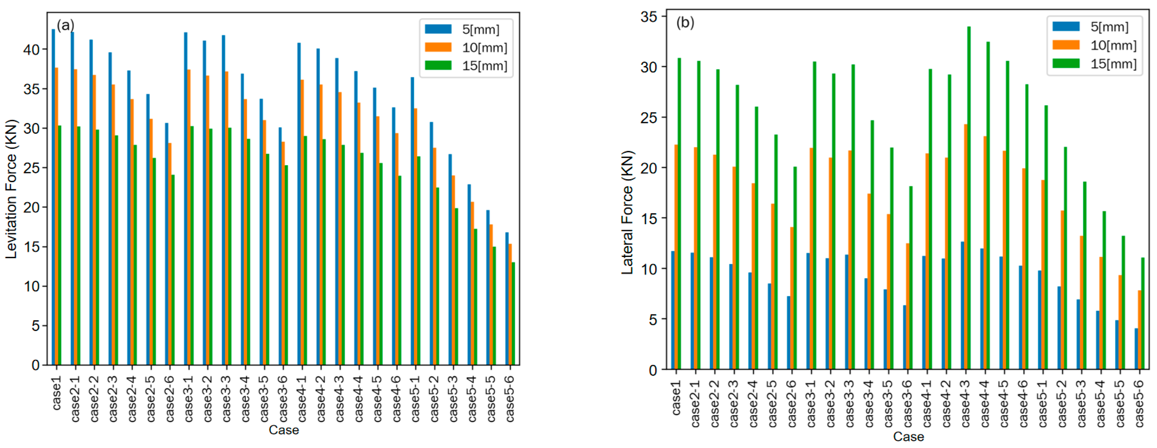
Figure 8 presents the levitation and lateral forces for all cases at a levitation height of 15 mm under lateral displacements of 5 mm, 10 mm, and 15 mm. As shown in
Figure 8a, the levitation force decreases with increasing lateral displacement across all cases. Furthermore, an increase in the key variable parameter of each specific case series also leads to a reduction in the levitation force generated by the corresponding Magnetic Wheelset. Analysis of the force variation from Case 5-1 to 5-6 indicates that the levitation force drops rapidly as the angle between the onboard permanent magnet and the permanent magnet track increases, demonstrating a high sensitivity of the levitation force to this inclination angle. In contrast, the most gradual change in levitation force is observed from Case 4-1 to 4-6, suggesting that variations in the center-to-center distance have the least pronounced effect. A minimal variation in levitation force is noted from Case 3-1 to 3-3; however, a sharp decrease occurs at Case 3-4. This suggests that when the inclination angle of the magnets relative to the horizontal plane exceeds 7.5°, lateral displacement induces a significant misalignment between the onboard and track magnets, resulting in a drastic attenuation of the magnetic field component responsible for levitation.
As shown in
Figure 8b, the lateral force increases with growing lateral displacement across all cases. Among them, the lateral force in Case 2 exhibits the most gradual rate of increase. In contrast, for Case 5, the lateral force declines rapidly, which correlates directly with the sharp decrease in its levitation force. The sharp drop in lateral force observed in Case 3-4 is attributed to the same cause as its reduction in levitation force. A sharp increase in lateral force occurs in Case 4-3, where the corresponding increased center-to-center distance is 12 mm—a value close to half the width of a single permanent magnet block. This indicates that when the lateral displacement exceeds half the width of the permanent magnet, the lateral force increases abruptly. However, with a further increase in the center-to-center distance, the effective opposing area between the onboard magnet and the track magnet continuously decreases, resulting in a subsequent reduction in both the levitation force and the lateral force.
The preceding analysis indicates that almost all mounting types result in a reduction in the lateral force, albeit at the cost of a decreased levitation force. However, the rates at which these forces decrease vary significantly among the different configurations. From an engineering perspective, it is desirable to maximize the levitation force while minimizing the lateral force. Therefore, a primary focus of subsequent research is to develop a method for rapidly identifying a mounting form that satisfies the levitation requirement while simultaneously achieving a significant reduction in lateral force.
4. Constraints on the Levitation and Lateral Forces
During vehicle operation, the levitation and lateral forces continually fluctuate. The magnitude of this variation is a critical indicator of the vehicle’s dynamic performance. Specifically, smaller force variations correspond to reduced vehicle oscillation, implying better stability and, consequently, superior dynamic performance. Therefore, the variation coefficient method (CV) is employed to analyze the degree of force variation under different mounting types to evaluate their levitation stability.
In the equation, CV stands for coefficient of variation. As a dimensionless indicator, it eliminates the influence of units and comprehensively reflects the relative fluctuation magnitude of the forces, where σ is the standard deviation and μ is the mean value. A smaller CV indicates more stable force characteristics and stronger robustness of the system against variations in operating conditions [
27,
28].
According to Equation (4), the coefficients of variation for the levitation force and lateral force are defined as follows:
where
and
are the coefficients of variation for the levitation force and lateral force under each case, respectively;
and
are the standard deviations of the levitation force and lateral force; and µ
FZ and µ
FX are the mean values of the levitation force and lateral force, among which
where N is the number of simulations, i is the levitation height, and j is the lateral displacement.
To screen for cases exhibiting high stability during vehicle operation, Case 1 is used as the benchmark. A case is deemed satisfactory only if it simultaneously satisfies the condition that both its levitation force CV and its lateral force CV are smaller than those of Case 1. This requirement is specified by Equation (8):
where
and
are the coefficients of variation for the levitation force and lateral force of Case 1, respectively. The calculation results are as shown in
Table 3.
As summarized in
Table 3, the CV for the lateral force is consistently greater than that for the levitation force, typically by a factor of approximately two. This indicates that the fluctuation of the lateral force in the permanent magnet levitation system is significantly more pronounced than that of the levitation force, which is a primary reason why the lateral vibration exceeds the vertical vibration. Using Case 1 as the benchmark, ten cases meet the requirement specified by Equation (8): Cases 2-1 through 2-5, 3-2, 3-3, and 4-4 through 4-6. Consequently, these ten configurations are identified as candidates for the next stage of selection.
While the CV serves as a dimensionless stability indicator that reflects the amplitude of data fluctuation, it does not convey the absolute magnitude of the data. As the preceding analysis has shown, all other cases result in a reduction in both levitation and lateral forces compared to Case 1. Therefore, it is necessary to establish a mean force threshold for all cases to prevent an excessive decrease in levitation force or an insufficient reduction in lateral force. Based on the actual operational data of the Xing guo Line, a 20% reduction from the levitation force in Case 1 still meets the safety requirements for the levitation gap. Accordingly, using the mean levitation and lateral forces of Case 1 as benchmarks, the mean levitation force under any case must be no less than 0.8 times
and the mean lateral force must be no greater than 0.8 times,
as specified in Equation (9).
In accordance with the requirements specified in Equation (9), the bar chart shown in
Figure 9 was generated.
As illustrated in
Figure 8 and in accordance with the requirement stipulated in Equation (9), the mean levitation force must be greater than 0.8 times that of Case 1, meaning its value should lie above the red line. Simultaneously, the mean lateral force must be less than 0.8 times that of Case 1, meaning its value should fall below the blue line.
Figure 8 indicates that only Cases 2-5, 3-4, and 3-5 satisfy these dual graphical criteria.
Based on the comprehensive analysis above, which considers both the stability requirement (CV) and the mean force threshold requirement, only Case 2-5 fulfills all conditions.
6. Conclusions
Taking the Xingguo permanent magnet levitation test line as the research background, this paper first established theoretical and finite element models for a single-point Halbach array and conducted experimental validation. Subsequently, a comparative analysis of the force characteristics of five types of Magnetic Wheelset mounting was performed. Furthermore, the optimal case was screened using a dual-constraint method based on the coefficient of variation and mean force threshold. Finally, a Simpack vehicle–track coupled dynamics model was employed to verify the improvement in dynamic performance achieved by the optimized configuration. The main conclusions are as follows.
Both the levitation force and lateral force of the Halbach array decay exponentially with increasing levitation gap. Under lateral displacement, Fz decreases while Fx increases, with the direction of Fx consistent with the displacement direction, confirming the characteristic of lateral negative stiffness.
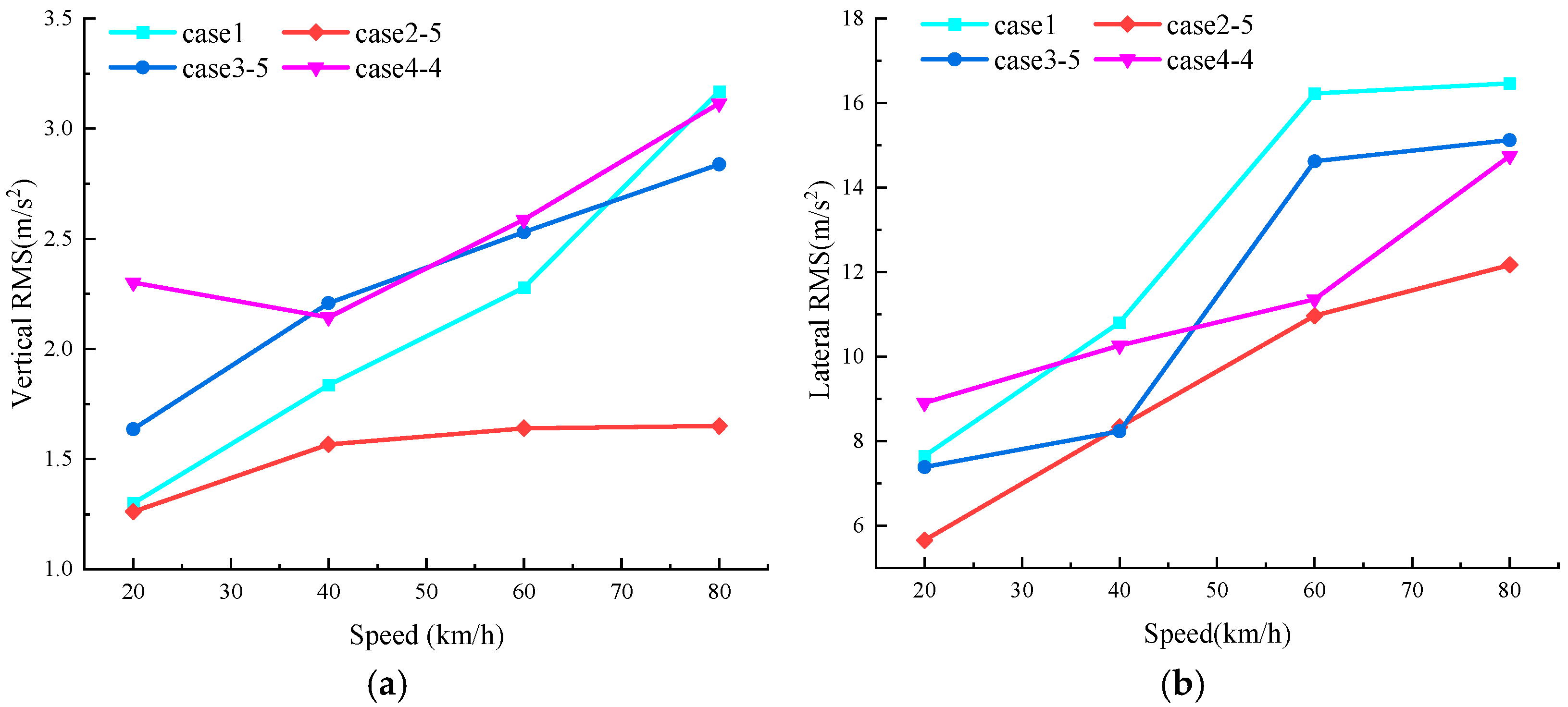
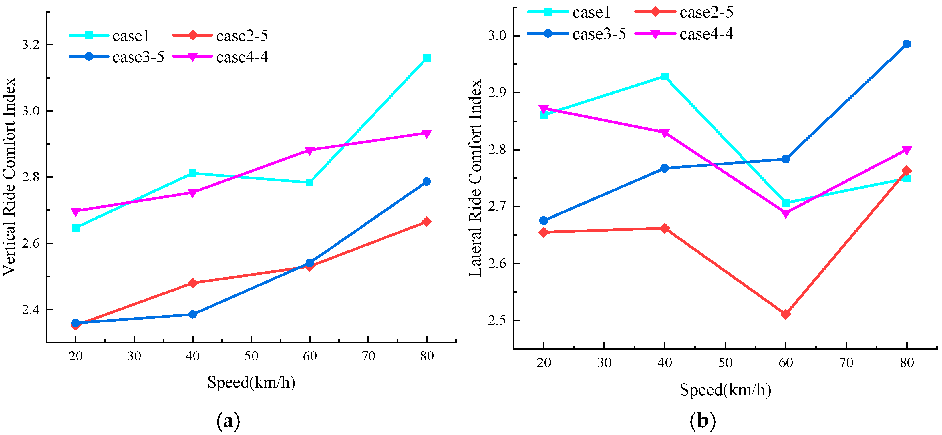
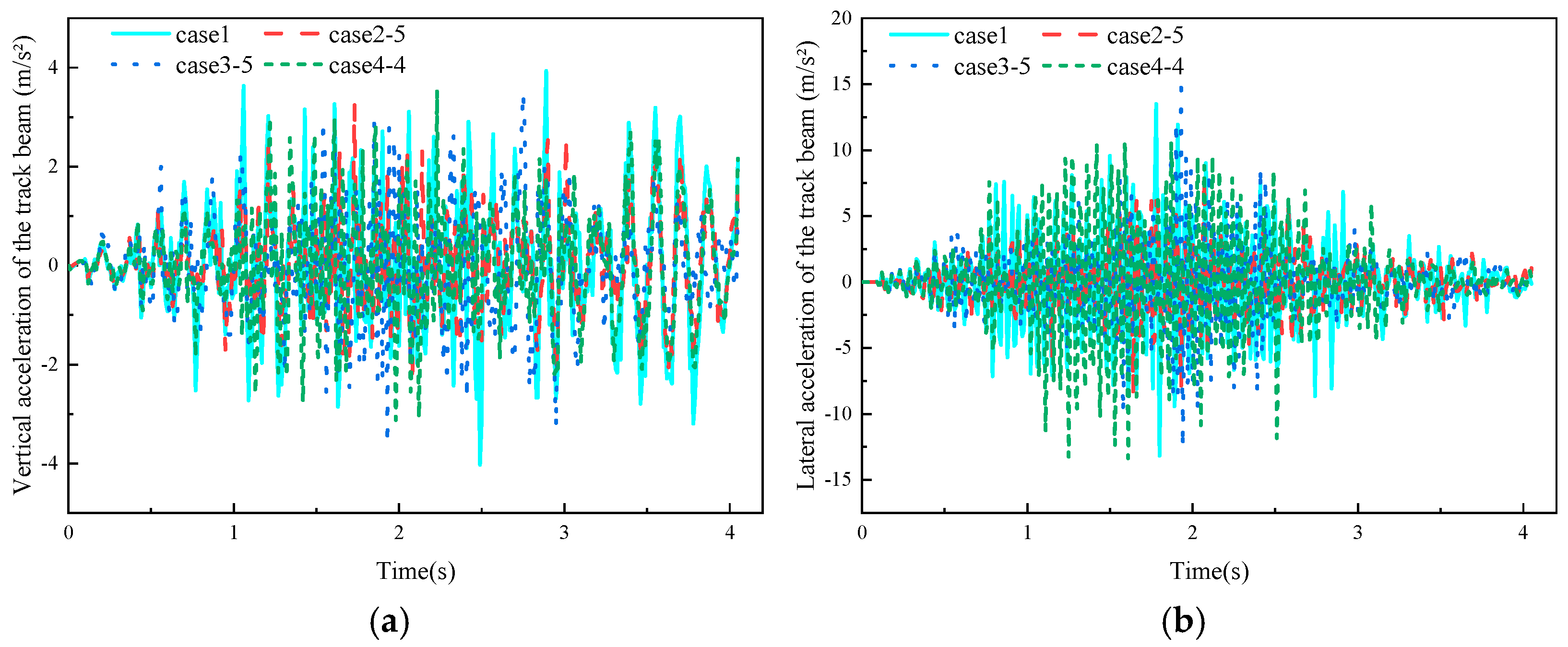
Among the five mounting types compared, the X-type installation at 25° performs optimally under the dual constraints of the coefficient of variation and the mean force threshold. It maintains sufficient levitation force while significantly reducing the lateral force. Simpack simulations show that, compared to the benchmark case (face-to-face installation), at a vehicle speed of 40 km/h, the RMS values of the bogie’s vertical and lateral vibration accelerations for the X-type 25° case are reduced by 14.7% and 23.8%, respectively. Concurrently, the vertical and lateral vibration accelerations of the track beam are reduced by 19.4% and 13.34%, respectively. Vehicle ride comfort is also significantly improved in this case.
The proposed multi-parameter constraint method, which integrates the CV and force thresholds, provides an efficient means for screening mounting forms and a viable pathway for optimizing the dynamics of permanent magnet levitation systems. The findings hold significant reference value for advancing the engineering application of permanent magnet levitation transportation.


