Abstract
With the continuous increase in high-speed train operation speeds, lightweight bogie design has become a key means to enhance dynamic performance, which also increases the risk of structural fatigue. High-frequency wheel–rail excitations are transmitted to the bogie frame and couple with its higher-order modes at around 200 Hz, inducing local high-frequency resonance. This coupling markedly increases the stress amplitude within the affected frequency range and accelerates vibration-induced fatigue damage. This study investigates the vibration fatigue characteristics of a bogie frame with an inner axle box under high-speed operation and wheel polygon wear conditions. Using a high-speed wheel–rail interaction test rig, dynamic stresses and the vibration acceleration of the bogie frame are measured under different speeds and polygon orders. Based on modal analysis and vibration fatigue methods, a high-frequency vibration fatigue assessment method for the bogie is developed. Wheel polygon significantly amplifies mid-to-high-frequency vibration energy, and for the bogie frame with an inner axle box, pronounced modal coupling is observed at around 200 Hz. In particular, under the 11th-order polygon condition, the equivalent stress at critical locations such as the traction motor seat weld seam exceeds the fatigue limit, while the effect of the 20th-order polygon is relatively mitigated. The proposed vibration fatigue assessment method provides a theoretical basis for the safe design and operational maintenance of high-speed trains with bogie frames with inner axle boxes.
1. Introduction
With the continuous increase in railway operating speeds, traditional structural design approaches are no longer sufficient to meet the requirements of high-speed operation. To accommodate higher speed demands, bogies must undergo structural lightweighting to satisfy dynamic performance requirements [1].
The bogie frame is prone to vibration-induced fatigue failures during service, which has attracted increasing research attention in recent years. Therefore, it is necessary to consider vibration environment spectra that align with both standards and actual operating conditions during the design stage to ensure accurate and reliable fatigue assessment [2]. In addition, machinery and transportation systems often exhibit high vibration levels and unmodeled dynamics, which can affect both structural performance and human comfort. For example, centrifugal loop dryer machines show significant operational vibration influencing process results [3], while electric scooters transmit vertical vibrations to riders, impacting hands and whole-body comfort and potentially posing long-term health risks [4]. These studies highlight the importance of frequency-domain vibration analysis for understanding vibration transmission, structural response, and human exposure. As the key load-bearing and power-transmitting structure of railway vehicles, the bogie is highly susceptible to fatigue damage. Therefore, research on the safety and reliability of bogie structures serves as a fundamental basis for ensuring the safe operation of railway trains [5,6].
Material optimization is one of the most effective approaches for achieving lightweight bogie design. Through the use of composite materials such as carbon fiber, the structural weight is reduced and the strength of the bogie frame is enhanced, thereby mitigating structural fatigue damage and lowering maintenance costs [7]. Alessio et al. [8] proposed a structural optimization method for light rail vehicles by employing sandwich structures and adhesive bonding techniques, which achieved a higher first-order modal frequency while maintaining lightweight design requirements. Ma et al. [9] developed a novel three-dimensional composite molding process and applied it to metro train bogies, conducting structural optimization for a braided composite bogie frame. Han et al. [10] established a rigid–flexible coupled dynamic model for high-speed train bogies made of carbon-fiber-reinforced laminates to analyze service failure behavior and further proposed an optimization scheme for composite layup design and local reinforcement to improve shear strength and delay failure.
Although the use of composite materials represents a reliable strategy for lightweighting railway vehicle structures, several challenges remain, including high manufacturing cost, uncertain dynamic performance, and complex vibration fatigue characteristics. To address these limitations, structural optimization of conventional metal bogies is still a practical and effective solution. Ding et al. [11] applied a structural stress-based fatigue-life prediction method in combination with the NSGA-II multi-objective genetic algorithm to perform thickness optimization, achieving a lightweight bogie frame design while ensuring sufficient strength. Cascino et al. [12] proposed a lightweight design method for metro train bogie frames that integrates topology optimization and sensitivity analysis, effectively reducing stress while satisfying manufacturability and lightweight requirements. Zou et al. [13] optimized the bogie suspension parameters of intercity EMUs through a hierarchical analysis of dynamic performance, using surrogate modeling techniques such as response surface modeling, Kriging models, and radial basis function neural networks. Xiao et al. [14] investigated a metro train bogie with an internal suspension configuration, established a multibody dynamic model to compare different suspension layouts, and validated the fatigue strength using measured load spectra.
Compared with other lightweight strategies such as the use of composite materials, suspension parameter optimization, and geometric structure optimization, bogies with inner axle boxes with an integrated suspension system offer a more reliable and safe approach that simultaneously meets lightweight and dynamic performance requirements. However, further verification and practical application are still needed for operation at higher speed grades.
Moreover, at higher operating speeds, wheel polygonization has become a common and severe wheel–rail contact condition. This phenomenon is particularly critical for bogies with inner axle boxes, whose structural modal frequencies and vibration characteristics differ significantly from those of conventional bogies, making the resulting wheel polygonization behavior and vibration response difficult to predict. The suspended components mounted on bogie frames with inner axle boxes are subjected to high-frequency excitations transmitted from the wheels through the bogie structure, which significantly influence the vibration fatigue behavior of welded joints. Therefore, evaluating the vibration fatigue behavior of bogie frames is essential for ensuring reliable structural design [15,16,17,18]. Peng et al. [19] developed a vehicle–track coupled dynamic model and, in combination with field test data, investigated the dynamic stress characteristics of bogie frames under wheel polygonization conditions. They further proposed a stress spectrum construction and fatigue-life prediction method that explicitly considers wheel polygonal wear. Zhang et al. [20] examined the influence of wheel polygonal wear on the vibration behavior of high-speed train braking systems by establishing a rigid–flexible coupled vehicle dynamic model and conducting line tests, taking into account environmental and nonlinear effects to analyze bogie dynamic performance. Shi et al. [21] investigated the resonance characteristics and fatigue behavior of metro train bogies under wheel polygonization conditions, combining field measurements with numerical simulations to evaluate dynamic responses across different track structures.
However, the loading conditions and vibration characteristics specified in general standards cannot fully capture the actual dynamic behavior and fatigue behavior of bogie frames with inner axle boxes, as their distinct structural configuration results in different modal characteristics and coupling responses under wheel–rail excitations. Consequently, the corresponding operating load conditions differ significantly from those of conventional bogies. Recently, studies focusing on the vibration fatigue characteristics of such structural configurations have remained relatively limited in the field of railway vehicle engineering. Nevertheless, for traditional bogie structures, bench testing has been widely adopted to investigate vibration environment and structural performance. Hou et al. [22] experimentally analyzed the dynamic performance of high-speed trains under various wheel wear conditions, using a multibody dynamic model to extract wheel–rail contact parameters for dynamic analysis. Nieminen et al. [23] conducted strain gauge measurements combined with physical calibration to analyze the dynamic stress behavior and fatigue assessment of bogies, enabling the identification of stress characteristics and the reconstruction of in-service load conditions. Seo et al. [24] performed standardized load tests on bogie frames through experimental testing, integrating nondestructive inspection, dynamic stress measurement, and finite element simulation to predict fatigue crack growth life. Therefore, bench testing serves as an effective method for evaluating the vibration characteristics and fatigue behavior of newly optimized bogie structures, especially when the dynamic response remains uncertain. Specifically, conducting vibration tests on bogies with inner axle boxes with a wheel–rail relationship test rig provides an accurate means to quantify the vibration characteristics and real operating loads of the bogie frame.
In summary, adopting an inner axle-box suspension configuration is an effective approach to achieving both lightweight bogie design and higher operating speeds. However, the vibration characteristics and fatigue behavior of bogies with inner axle boxes under high-speed operation and complex wheel–rail interaction conditions require more comprehensive experimental testing and evaluation. In this study, a high-speed wheel–rail relationship test rig is employed to measure the dynamic stress and vibration acceleration of the bogie frame. A power spectral density (PSD) spectrum of traction motor vibration acceleration is constructed to represent the excitation characteristics under high-speed operating conditions. Based on these data, a vibration fatigue assessment method is developed for a bogie frames with an inner axle box. Furthermore, the vibration fatigue damage incurred by the bogie frame is analyzed under different operating speeds and wheel polygonization conditions.
The remainder of this paper is organized as follows. Section 2 describes the experimental scheme for a bogie frame with an inner axle box and the wheel polygonization conditions considered in the tests. Section 3 presents the modal analysis, dynamic stress, and vibration acceleration measurements of the bogie frame. Section 4 analyzes and evaluates the fatigue damage of the bogie frame under wheel polygonization and high-speed operating conditions. Finally, Section 5 provides the conclusions.
2. Test Method
Bogie frames with inner axle boxes not only achieve optimized structural lightweighting but also lower the center of gravity, thereby improving the running stability of vehicles and effectively reducing the vibration characteristics of axle boxes. The tested bogie had an axle load of 15 t, a nominal wheel diameter of 920 mm, and a wheel tread profile type LMB10. The axle box positioning was realized through a locating tie rod mechanism. The bogie frame with an inner axle box was installed on a high-speed wheel–rail relationship test rig for experimental investigation. The test rig was equipped with rail wheels of 3000 mm in diameter. The testing speed was controlled within the range of 300–400 km/h, with tests conducted at increments of 10 km/h. To ensure the reliability of the experimental data, the bogie frame was operated under stable conditions for 30 s at each speed level, and all speed levels were repeated twice sequentially. A schematic of the high-speed wheel–rail relationship test rig is illustrated in Figure 1. The structure of the high-speed bogie with an inner axle box has undergone significant changes compared to traditional external-axle-box bogies; the bogie model is shown in Figure 2.
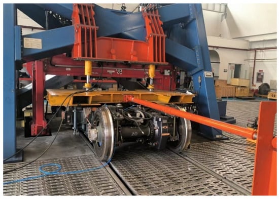
Figure 1.
High-speed wheel–rail interaction test rig.
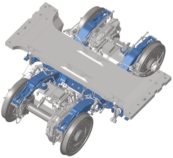
Figure 2.
Model of the bogie frame with an inner axle box.
Based on the EN 13749 standard [25], the stress distribution of the bogie frame with an inner axle box was calculated. The resulting stress contour under the standard fatigue load conditions was illustrated in Figure 3. According to engineering experience and the finite element simulation results derived from the standard loading conditions, several critical stress measurement locations were identified on the bogie frame. These locations primarily included the weld seam on the traction motor, gearbox, and traction rod, as well as the stress concentration regions near the frame ends. The arrangement of strain gauges for stress measurement is illustrated in Figure 4.
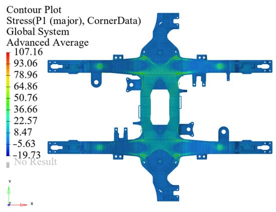
Figure 3.
Stress contour of the bogie frame with an inner axle box.
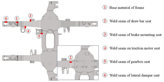
Figure 4.
Strain gauge arrangement on the bogie frame with an inner axle box.
A strain measurement system was established for the bogie frame using temperature-compensated strain gauges configured in a quarter-bridge circuit. Temperature-self-compensated strain gauges were employed in this study. Owing to their special grid material, the thermal output was negligible within the normal testing temperature range, and therefore no additional compensation gauges were required. A compensation factor of 11, which corresponds to stainless-steel substrates, was selected, covering the temperature range of −30 °C to 80 °C and satisfying the experimental environment. After installation, bridge balancing and zero-offset calibration were performed to ensure the accuracy and repeatability of the strain measurements. Each strain gauge had a nominal resistance of 120 Ω, a measurement range of 40,000 με, and a gauge factor of 2.18. The data acquisition system operated at a sampling frequency of 10 kHz. Strain measurements were conducted at six critical locations and their symmetrical counterparts on the bogie frame. For each location, the stress response was measured on the side corresponding to the direction of the roller track. Dynamic tests were performed across a speed range of 50–400 km/h. Representative strain gauge installations are illustrated in Figure 5.
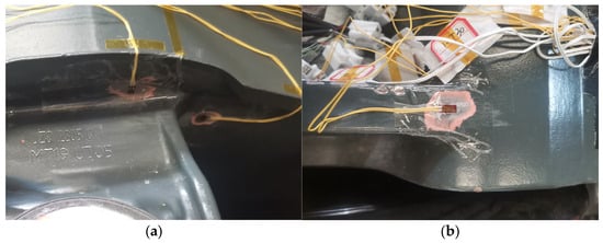
Figure 5.
Strain measurement of the bogie frame with an inner axle box: (a) weld seam on traction motor seat; (b) base material of frame.
Wheel polygon formation results from multiple factors, including initial wheel defects, wheel–rail coupled vibrations, and thermoelastic instability during tread braking. Among these, the excitation of local bending modes of the rail is generally considered the primary contributor to high-order polygonal wear observed in high-speed trains [26]. High-order wheel polygons, notably the 11th and 20th orders, frequently occur in service due to local rail bending modes and wheel–rail coupled vibration [27].
To investigate the influence of wheel polygon on the vibration response and stress state of the bogie frame with an inner axle box, artificially ground wheel profiles were produced and validated through roundness measurements. The processed wheel roundness and the corresponding idealized reference curves are presented in Figure 6. To calibrate the grinding accuracy and characterize the processed profiles, roughness-level tests were performed (Figure 7). Wheel tread wear on both sides of a wheelset generally promotes the formation of higher-order polygons. In this study, representative polygon conditions were used to assess their effect on bogie vibration and fatigue; full lifetime evolution was not explicitly analyzed.

Figure 6.
Irregularity amplitude: (a) initial wheel; (b) 11th-order polygon; (c) 20th-order polygon.
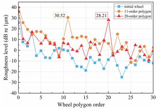
Figure 7.
Results of wheel roughness orders.
The dominant harmonic components corresponding to the 11th and 20th orders exhibit a roughness level of approximately 30 dB according to the spectral processing approach adopted in this study. Grinding does not fully reproduce the idealized curve or every detail of in-service profiles. Nevertheless, because the present study focuses on the vibration characteristics associated with the dominant 11th- and 20th-order excitations, the post-processing roughness and roundness evaluations confirmed that the manufactured profiles sufficiently reproduced the primary excitation components of interest.
3. Vibration Characteristics
3.1. Operational Modal Analysis
The operational mode shapes of the bogie frame with an inner axle box under different running speeds are illustrated in Figure 8, with the dominant frequency located around 200 Hz. The vibration mode within this frequency range primarily represents the local bending–torsion coupled deformation of the axle-box region and the longitudinal beams. At low running speeds (100 km/h), deformation was mainly concentrated in the side beams of the frame, showing a symmetric bending pattern. When the speed increased to 300 km/h, the modal displacement distribution remained nearly unchanged, indicating that the vibration energy of this structural mode did not significantly increase within this speed range. However, at 200 km/h and 400 km/h, the coupling effect between the bending of the cross beam and the lateral bending of the side beam became more pronounced, suggesting a potential resonance tendency near these speed levels. Overall, the working mode around 210 Hz exhibited a typical coupled vibration characteristic of bogie frames, which is a key factor in determining the vibration fatigue behavior of the bogie frame with an inner axle box.
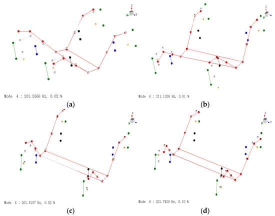
Figure 8.
Operating mode shapes of the bogie frame with an inner axle box near 200 Hz: (a) 100 km/h; (b) 200 km/h; (c) 300 km/h; (d) 400 km/h. (The red color indicates the bogie frame deformation mode, gray represents the undeformed bogie frame, blue denotes the gearbox, black corresponds to the traction motor, and green indicates the axle box).
The frequency response function (FRF) of the bogie frame with an inner axle box reached its maximum value at around 200 Hz, as illustrated in Figure 9. In this study, modal analysis and fatigue assessment focus on the frequency range where significant resonance was observed in the measured signals. The corresponding modal shape indicates that the overall frame underwent vertical deformation, while the side beams deformed in the opposite direction. The regions of stress concentration were primarily located in the base material of the cross beams. The modal shape of a conventional bogie frame with an outer axle box is illustrated in Figure 10. Compared with this traditional configuration, the bogie frame with an inner axle box exhibited a higher degree of modal stress concentration, which was mainly localized in the base material of the cross-beam plates rather than at the welded joints. Therefore, the vibration fatigue behavior of the bogie frame with an inner axle box was not significantly deteriorated, despite the increased local stress concentration. Furthermore, the total mass of the bogie frame with an inner axle box was reduced from 1.84 t to 1.03 t, achieving a 44% reduction in weight. Since this weight reduction was achieved through global structural form optimization rather than simple thickness or shape adjustments, the modal stress index did not show a significant increase.
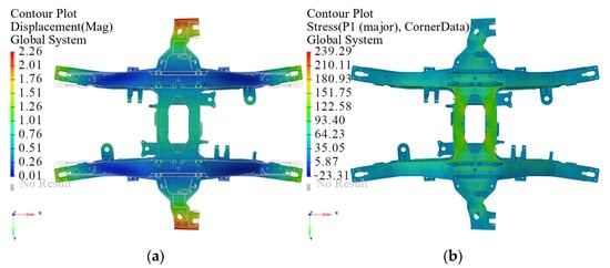
Figure 9.
Modal shape of the bogie frame with an inner axle box: (a) displacement mode; (b) stress mode.
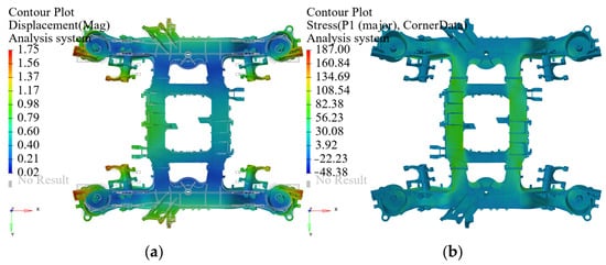
Figure 10.
Modal shape of the CRH3-type bogie frame: (a) displacement mode; (b) stress mode.
3.2. Vibration Transmission Characteristics
The vertical vibration transmission ratio from the axle box to the end of the bogie frame under different speeds and wheel polygon conditions is illustrated in Figure 11. In the low-frequency range (0–100 Hz), the overall transmission ratio remains relatively high, indicating that the vibration energy transmitted from wheel–rail excitation was amplified by the suspension system. As the frequency increased, the transmission ratio gradually decreased, exhibiting a typical attenuation trend. At a speed of 100 km/h, the vibration energy was mainly concentrated below 50 Hz, with a pronounced transmission peak in the low-frequency range, while the transmission ratio in the high-frequency band remained relatively low. The periodic excitation induced by the wheel polygon led to significant amplification in the 50–150 Hz range, implying that the geometric irregularity of the wheel enhanced the low-frequency response of the suspension system. When the speed increased to 200 km/h and above, the vibration transmission characteristics gradually shifted toward the higher frequency range. A local amplification near 200 Hz became evident, suggesting that excitation around this frequency coupled with modal shape to further enhance the high-frequency response transmitted to the bogie frame.
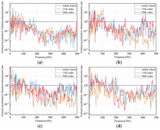
Figure 11.
Vibration transmissibility from axle box to frame end of a bogie frame with an inner axle box: (a) 100 km/h; (b) 200 km/h; (c) 300 km/h; (d) 400 km/h.
As the running speed continued to increase, the transmission ratio exhibited multiple peaks in the mid-to-high-frequency band (200–400 Hz), where the primary vertical dampers were less effective in suppressing vibration transmission. The high-order polygon condition caused the vibration energy spectrum to extend toward higher frequencies, with vibration amplitudes above 200 Hz increasing markedly. This result indicates that high-order wheel polygons have a more pronounced influence on local structural vibration under high-speed conditions. At 300 km/h and 400 km/h, the high-frequency vibrations in components induced by the wheel polygon further intensified. In particular, the superposition of transmission peaks around 200 Hz corresponds to the bending–torsion coupled mode of the bogie frame, suggesting a resonance interaction between excitation and structural dynamics. The vibration energy transmission near 200 Hz was a primary contributor to the dynamic response of the bogie frame with an inner axle box, and this localized resonance band may serve as a primary frequency range for fatigue damage initiation.
The acceleration waterfall spectra of the traction motor on the bogie frame with an inner axle box under the initial wheel and polygonal wheel conditions are illustrated in Figure 12. Under the initial wheel condition, the vibration energy was mainly concentrated within the 100–200 Hz frequency range and increased slightly with the speed. This indicates that the vibration response of the system was dominated by low-frequency elastic modes and the overall dynamic performance remained stable. When the wheel polygon order increased to the 11th, a distinct energy peak appeared around 200 Hz, and a pronounced peak was also observed in the 100–200 Hz frequency range near a speed of 200 km/h. As the polygon order further increased to the 20th, the vibration amplitudes in the frequency range above 300 Hz rose significantly, accompanied by the emergence of multiple energy clusters. This indicates that high-order wheel polygons induced multi-modal coupled vibrations in the traction motor due to intensified wheel–rail irregularity excitations. For the bogie frame with an inner axle box, the local energy peak near 200 Hz corresponds closely to the structural modal characteristics of the frame. The wheel polygon not only altered the spectral distribution of the traction motor’s vibration acceleration but also markedly increased the energy density in the mid- and high-frequency bands. Even modal frequencies that were not excited under normal wheel conditions became activated due to the polygon-induced excitation, exhibiting distinct resonance peaks, particularly near 162.17 Hz, 204.32 Hz, 345.15 Hz, and 429.93 Hz.
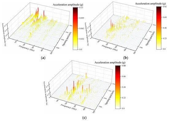
Figure 12.
Waterfall plot of traction motor acceleration: (a) initial wheel; (b) 11th-order polygon; (c) 20th-order polygon.
The vibration acceleration of the bogie frame with an inner axle box was evaluated against the requirements of IEC 61373 [28], and the vertical vibration acceleration power spectral density (PSD) curves of the traction motor were compiled for different speeds. These curves were compared with the Category 2 standard PSD spectrum for bogie-mounted equipment specified in IEC 61373. The results are illustrated in Figure 13. Under the initial wheel condition, the vibration energy at all speeds was mainly distributed within the 10–200 Hz frequency range, remaining well below the standard limit. This result indicates that the bogie frame with an inner axle box exhibited excellent vibration isolation and stable dynamic performance under normal wheel–rail conditions. However, when wheel polygons occurred, local peaks within the high-frequency range of 100–500 Hz approached or even exceeded the IEC 61373 limit curve. Nevertheless, the overall vibration load of the bogie frame with an inner axle box remained within acceptable limits under typical operating conditions, satisfying the design and fatigue behavior requirements for bogie-mounted equipment.
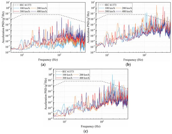
Figure 13.
Vertical acceleration PSD of the traction motor on the bogie frame with an inner axle box: (a) initial wheel, (b) 11th-order polygon; (c) 20th-order polygon.
3.3. Stress Characteristics
The vibration acceleration reflects the overall dynamic response of the bogie, while its fatigue behavior was governed by the distribution and coupling behavior of modal stresses. To further elucidate the transmission mechanism of dynamic loads induced by wheel polygon, a dynamic stress analysis was performed for the weld seam on the traction motor seat of the bogie frame, as illustrated in Figure 14. The results show that the stress energy was mainly concentrated in the low-to-medium frequency range of 50–250 Hz and increased significantly with the wheel polygon order. This result indicates that the high-frequency components of the wheel-rail contact excitation were amplified during vibration transmission and led to modal stress coupling at local regions such as the weld seam of the motor seat. Notably, the dominant frequency bands of the stress spectra corresponded closely to the main peaks of motor acceleration, while the maximum stress resonance generally appeared in the lower-frequency range.
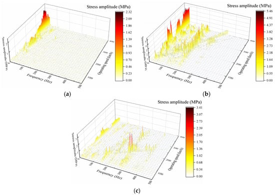
Figure 14.
Waterfall plot of stress at the weld seam on traction motor seat of the bogie frame with an inner axle box: (a) initial wheel; (b) 11th-order polygon; (c) 20th-order polygon.
Under the initial wheel condition, the stress amplitudes were relatively low and mainly distributed below 100 Hz, corresponding to the fundamental excitation and primary modal response under smooth wheel–rail contact. When the wheel polygon order increased to the 11th order, a pronounced energy band appeared in the 150–250 Hz range, and the stress amplitude rosed above 5 MPa. This suggests that the higher-order polygon introduced additional high-frequency excitations, which coupled with the local modes of the bogie frame and cause amplitude amplification. As the polygon order further increased to the 20th, the high-frequency stress energy extended over a wider frequency range, with local peaks exceeding 3 MPa. This evolution indicates a transition from a single-mode-dominated response to a multi-modal coupled vibration behavior. The trend is consistent with the acceleration response of the traction motor, confirming that high-frequency excitations induced by wheel polygonization directly affect the local stress level of weld seams through dynamic coupling in the wheelset frame system.
4. Fatigue Performance Assessment
4.1. Frequency-Domain Fatigue Evaluation Method
For the bogie frame with an inner axle box, vibration fatigue assessment was typically conducted using random vibration fatigue evaluation methods. Among these, the Dirlik method is recognized for its relatively high accuracy [29]. The Dirlik method models the probability density function (PDF) of stress ranges as a combination of three different distributions: exponential distribution, modified Rayleigh distribution, and standard Rayleigh distribution [30]. The probability distribution of rainflow cycle amplitudes is expressed as follows:
where r is the rainflow range and the coefficients A1, A2, A3, R, Q, and xm are defined as follows:
Translating the dispersion of the Palmgren–Miner law into a continuous distribution of amplitudes [31], the fatigue cumulative damage ratio based on Equation (1) is calculated as follows:
where D is the fatigue damage during the test mileage, n is the number of rainfall cycles counted over the full test time horizon, and N(S) is the number of cycles that fail at the constant amplitude S.
By combining the variable-amplitude stress spectrum with constant-amplitude stress through the principle of equivalent damage substitution, the equivalent stress is calculated as follows:
where σeq is equivalent stress; L∑ is the full design life mileage; for the bogie frame evaluated in this study, the design mileage is 18 million km, corresponding to an approximate service life of 30 years; L1 is the test mileage.
4.2. Fatigue Analysis
A vibration fatigue analysis is conducted for the bogie frame with an inner axle box, with the PSD of the traction motor seat weld seam stress under high-speed operation shown in Figure 15. Under the initial wheel condition, the stress PSD is distributed relatively uniformly across the frequency range, without pronounced high-amplitude peaks. Under the 11th-order wheel polygon condition, distinct peaks appear in the frequency range above 100 Hz, with a significant increase in stress amplitude. As the speed increases, these peaks shift toward higher frequencies, while the amplitudes decrease when away from the modal frequencies. This result indicates that polygonal wheel–rail excitation markedly amplifies the high-frequency components of the frame stress, exacerbating fatigue damage at the welds. Under the 20th-order wheel polygon condition, the PSD response becomes more intense, while exhibiting lower amplitudes compared to the 11th-order polygon, with multiple peaks appearing in the mid-frequency range below 100 Hz.
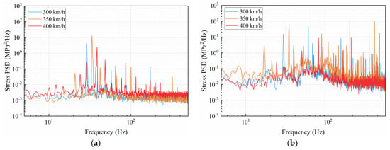
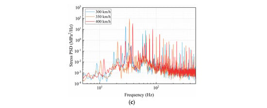
Figure 15.
Stress PSD at the weld seam of the traction motor seat on the bogie frame with an inner axle box: (a) initial wheel; (b) 11th-order polygon; (c) 20th-order polygon.
Using the S–N curves of welded joints from the IIW standard [32], fatigue-life prediction is conducted. The influence of weld quality classes is not explicitly considered in this study. In practical engineering applications, lower weld quality classes typically require higher safety factors to ensure adequate fatigue resistance. It is noted that fatigue-life estimation is highly sensitive to the statistical scatter of the S–N curve. Each S–N curve is associated with a 75% confidence level at a 95% survival probability, which is used to calculate the equivalent stress confidence interval. The equivalent stress at two critical locations of the bogie frame with an inner axle box under different operating speeds is illustrated in Figure 16. The equivalent stress of the frame is significantly affected by the wheel polygon order. Under the initial wheel condition, the stress levels at all speed levels are well below the fatigue limit of the material, indicating a high structural safety margin. Under the 11th-order wheel polygon, the equivalent stress exceeds the allowable limit in the speed ranges of 100–150 km/h and 250–300 km/h, failing to meet the operational requirements. In contrast, under the 20th-order polygon condition, the equivalent stress remains within acceptable limits. At the base material of the frame end, the equivalent stress is generally low; even with increased vehicle speed and the presence of wheel polygon conditions, the stress remains below the material fatigue limit.
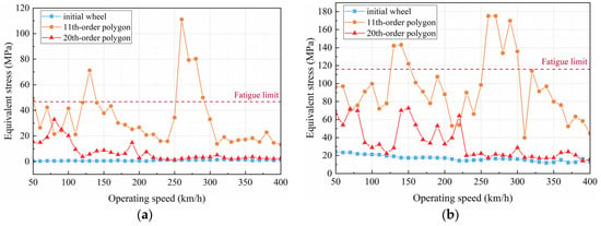
Figure 16.
Equivalent stress at critical locations of the bogie frame with an inner axle box: (a) weld seam on traction motor seat; (b) base material of frame.
The cumulative fatigue damage at critical locations is shown in Figure 17. Under conditions without wheel polygon or with 20th-order polygon below 30 dB, the resonance stress does not lead to fatigue failure. However, under the 11th-order polygon condition, severe resonance occurs at 120–150 km/h and 250–300 km/h, where the maximum accumulated damage reaches 13.36, indicating fatigue failure. Accordingly, when the 11th-order wheel polygon occurs, the service duration should not exceed two years, considering the designed 30-year service life of the bogie frame.
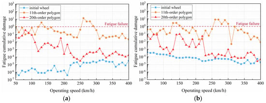
Figure 17.
Fatigue cumulative damage at critical locations of the bogie frame with an inner axle box: (a) weld seam on traction motor seat; (b) base material of frame.
In order to analyze the operation of the bogie frame with an inner axle box under high-speed conditions, the hazardous operating conditions of the bogie are evaluated. The overall variation of the frame stress amplitude with speed does not exhibit a clear linear relationship, while it is highly correlated with the coupling between the frame modal frequencies and wheel rotational frequencies. The stress vibration amplitude is positively correlated with the wheel rotational speed, the self-excited oscillation frequency of the bogie, and the reciprocal of the polygon order. Therefore, the hazardous operating speed ranges are identified as follows:
where v is the vehicle running speed in mm/s, Dw is the nominal circular diameter of the wheel in mm, fn is the bogie self-oscillation frequency of the nth order in Hz, and i is the number of wheel polygon orders, according to the wheel diameter condition, the conversion relation equation between rotational speed v’ and vehicle running speed v is: v’ = v/πDw = 0.096 v.
The influence of polygon amplitude on stress or acceleration amplitude is relatively minor compared to the effect of frequency. Based on the modal test results, the hazardous speed levels of the bogie frame with an inner axle box are listed in Table 1, taking into account the harmonic effects of wheel–rail excitation. The vibration acceleration resonance amplitudes around 200 Hz are relatively higher. Under the 11th-order wheel polygon condition, speeds of 190 and 380 km/h, and under the 20th-order polygon condition, speeds of 110, 220, and 330 km/h, correspond to significant resonance, leading to a notable reduction in fatigue behavior, which is consistent with the trends observed in the fatigue analysis. In service, speed sensors and accelerometers may be used to identify abnormal vibration signatures associated with polygon-induced excitation and monitor the running safety of the bogie. Once pronounced wheel polygon is detected, reprofiling should be scheduled promptly to suppress high-frequency excitation and mitigate fatigue-damage accumulation. In conjunction with the fatigue-life prediction results, the bogie frame with an inner axle box satisfies the design requirements for high-speed operation at approximately 400 km/h.

Table 1.
Modal frequency of the frame coupled to the wheel velocity class.
Based on the fatigue-life results from all dynamic stress measurement points, a comprehensive analysis of the fatigue behavior of the bogie frame with an inner axle box is conducted. The equivalent stress at the critical measurement points is presented in Table 2. The base material of the frame end, as well as the traction motor seat weld seam and draw bar weld seam, exhibit the highest stress levels as they lie along the vibration transmission path and thus represent the weakest locations in terms of fatigue behavior.

Table 2.
Equivalent stress amplitude value of the bogie frame.
Under the 11th-order wheel polygon condition, significant stress concentration occurs at the frame base material and the traction motor seat weld seam, with equivalent stresses of 135.73 MPa and 32.97 MPa at 300 km/h, respectively, exceeding the fatigue limit of these components. Compared to the 11th-order polygon, the effect of the 20th-order wheel polygon is relatively mitigated, and stresses at locations such as the brake mounting weld seam remain low. In practical applications, the variation of stress with speed exhibits nonlinear characteristics with notable resonance effects. Therefore, establishing reliable wheel reprofiling strategies is critical to ensure the fatigue safety of the frame.
5. Conclusions
In this study, the vibration characteristics and fatigue behavior of the bogie frame with an inner axle box under wheel polygon conditions are analyzed. Numerical simulations and a high-speed wheel–rail test rig are used to perform modal tests, vibration acceleration measurements, and dynamic stress evaluations, with a primary focus on traction motor vibrations and the stress and fatigue behavior of motor seat weld seams. The fatigue behavior of the bogie frame with an inner axle box meets the design requirements, and the vibration acceleration PSD spectra fall within the limits specified by the IEC 61373 standard.
A vibration fatigue damage assessment method under wheel polygon conditions is developed, providing a new approach for evaluating high-frequency vibration fatigue in railway vehicle structures. This method accounts for the frequency characteristics and distribution of vibration stress, effectively characterizing the frequency-domain behavior of bogie suspension components, and allows for accurate assessment of fatigue damage in support weld seams.
The mass of the bogie frame with an inner axle box was reduced by 44%. Although the modal stress concentration slightly increased, the fatigue behavior of the weld regions was not significantly affected. Based on the coupling between modal frequencies and wheel rotational frequencies, the hazardous speed levels were identified as 190 km/h and 380 km/h under 11th-order wheel polygonization and 110 km/h, 220 km/h, and 330 km/h under 20th-order polygonization. Overall, the bogie frame with an inner axle box met the fatigue-life requirements for high-speed operation up to 400 km/h under conditions without severe wheel polygonization or other harsh operating factors. However, once wheel polygonization occurs—particularly 11th-order polygonization—reprofiling should be scheduled within one week, and the corresponding hazardous speed ranges should be avoided during operation to suppress high-frequency vibration and mitigate fatigue-damage accumulation.
Author Contributions
Conceptualization, T.G.; methodology, Q.D.; validation, Y.W.; formal analysis, M.H.; investigation, G.C.; resources, B.C. and M.H.; writing—original draft, T.G.; writing—review and editing, Q.D.; visualization, G.C.; supervision, Y.W.; project administration, B.C.; funding acquisition, T.G. All authors have read and agreed to the published version of the manuscript.
Funding
The authors gratefully acknowledge the financial support provided by the Science and Technology Research and Development Programme Project of China National Railway Administration Group, grant number 2022YJ322, the China National Railway Group Co., Ltd. Research Project, grant number SJ2024-024.
Data Availability Statement
The datasets used and/or analyzed during the current study are available from the corresponding author upon reasonable request.
Conflicts of Interest
The authors Tao Guo and Guojie Cai were employed by Bogie Technology Centre, CRRC Tangshan Co., Ltd. The author Maorui Hou was employed by the China Academy of Railway Sciences Corporation Limited. The remaining authors declare that the research was conducted in the absence of any commercial or financial relationships that could be construed as a potential conflict of interest.
References
- Xiu, R.; Spiryagin, M.; Wu, Q.; Yang, S.; Liu, Y. Fatigue Life Assessment Methods for Railway Vehicle Bogie Frames. Eng. Fail. Anal. 2020, 116, 104725. [Google Scholar] [CrossRef]
- Wang, S.; Wu, P.; Song, Y.; Liu, C.; Ye, Y.; Li, F. Vibration Environment Spectrum Investigation of Metro Bogie Frame End. Eng. Fail. Anal. 2024, 157, 107865. [Google Scholar] [CrossRef]
- Karpenko, M.; Ževžikov, P.; Stosiak, M.; Skačkauskas, P.; Borucka, A.; Delembovskyi, M. Vibration Research on Centrifugal Loop Dryer Machines Used in Plastic Recycling Processes. Machines 2024, 12, 29. [Google Scholar] [CrossRef]
- Karpenko, M.; Prentkovskis, O.; Skačkauskas, P. Analysing the Impact of Electric Kick-Scooters on Drivers: Vibration and Frequency Transmission during the Ride on Different Types of Urban Pavements. Eksploat. Niezawodn-Maint. Reliab. 2025, 27, 1–14. [Google Scholar] [CrossRef]
- Wang, B.J.; Xie, S.Q.; Li, Q.; Ren, Z.S. Fatigue Damage Prediction of Metro Bogie Frame Based on Measured Loads. Int. J. Fatigue 2022, 154, 106532. [Google Scholar] [CrossRef]
- Lu, Y.; Zheng, H.; Zeng, J.; Chen, T.; Wu, P. Fatigue Life Reliability Evaluation in a High-Speed Train Bogie Frame Using Accelerated Life and Numerical Test. Reliab. Eng. Syst. Saf. 2019, 188, 221–232. [Google Scholar] [CrossRef]
- Seurat, C. Carbon Fibre Based Bogie: Challenging applications in composites: Railway compliant, recycled carbon fibre based bogie. Sampe J. 2021, 57, 6. [Google Scholar]
- Alessio, C.; Meli, E.; Rindi, A. A Strategy for Lightweight Designing of a Railway Vehicle Car Body Including Composite Material and Dynamic Structural Optimization. Railw. Eng. Sci. 2023, 31, 340–350. [Google Scholar] [CrossRef]
- Ma, Q.; Qin, X.; Gan, X.; Wang, Y. Study on Structural Optimization of Braid-and-Lay Integrated Carbon Fiber Reinforced Polymer for Metro Bogie. Polym. Compos. 2023, 44, 6419–6439. [Google Scholar] [CrossRef]
- Han, Y.; Ruichen, W.; Paul, A.; David, C.; Wenjie, F. Analysis of Failure Mechanisms for CFRP Laminated Composite Bogie Frames of the next Generation High-Speed Trains under Service Environment. Eng. Fail. Anal. 2025, 178, 109701. [Google Scholar] [CrossRef]
- Ding, L.; He, Z.; Chen, B. Strength Assessment and Lightweight Optimization Design of a Bogie Frame Based on the Structural Stress Method. Int. J. Struct. Integr. 2024, 16, 159–186. [Google Scholar] [CrossRef]
- Cascino, A.; Meli, E.; Rindi, A. A New Strategy for Railway Bogie Frame Designing Combining Structural–Topological Optimization and Sensitivity Analysis. Vehicles 2024, 6, 651–665. [Google Scholar] [CrossRef]
- Zou, H.; Wu, Q.; Zou, X. Research on Optimization Design of Suspension Parameters of Railway Vehicle Bogies Based on Surrogate Model. Multimed. Tools Appl. 2025, 84, 35091–35109. [Google Scholar] [CrossRef]
- Xiao, Q.; Zhang, M.; Chen, D.; Wang, X.; Lei, C. The Operational Performance and Fatigue Life Analysis of Internal Suspension Bogie. J. Braz. Soc. Mech. Sci. Eng. 2025, 47, 634. [Google Scholar] [CrossRef]
- Guo, L.; Li, G.; Chen, C.; Zhang, Y.; Zhang, H.; Gong, D. Vibration Fatigue Characteristics of a High-Speed Train Bogie and Traction Motor Based on Field Measurement and Spectrum Synthesis. Machines 2025, 13, 613. [Google Scholar] [CrossRef]
- Wu, X.; Zhang, Z.; Cai, W.; Yang, N.; Jin, X.; Wang, P.; Wen, Z.; Chi, M.; Liang, S.; Huang, Y. A Critical Review of Wheel/Rail High Frequency Vibration-Induced Vibration Fatigue of Railway Bogie in China. Railw. Sci. 2024, 3, 177–215. [Google Scholar] [CrossRef]
- Wei, L.; Sun, Y.; Zeng, J.; Qu, S. Experimental and Numerical Investigation of Fatigue Failure for Metro Bogie Cowcatchers Due to Modal Vibration and Stress Induced by Rail Corrugation. Eng. Fail. Anal. 2022, 142, 106810. [Google Scholar] [CrossRef]
- Xiao, X.; Wang, Q.; Zhang, Y.; Han, J.; Jin, X. The Dynamic Characteristics of the Hydraulic Damper on the High-Frequency Vibration Transmission of the Bogie. Int. J. Rail Transp. 2025, 2, 1–20. [Google Scholar] [CrossRef]
- Peng, B.; Wu, X.; Zhang, Z.; Yang, N.; Hu, F.; Wang, P.; Mi, C.; Chi, M.; Wu, S. Determination of Wheel Polygonal Wear Limit and Fatigue Life of Railway Bogie Frames Considering Wheel/Rail Excitation. Eng. Fail. Anal. 2025, 169, 109220. [Google Scholar] [CrossRef]
- Zhang, L.; Wang, Z.; Wang, Q.; Mo, J.; Feng, J.; Wang, K. The Effect of Wheel Polygonal Wear on Temperature and Vibration Characteristics of a High-Speed Train Braking System. Mech. Syst. Signal Process. 2023, 186, 109864. [Google Scholar] [CrossRef]
- Shi, Y.; Mao, Q.; Wang, Q.; Dai, H.; Peng, X.; Dong, C. Research on Wheel Polygonal Wear Based on the Vehicle–Track Coupling Vibration of Metro. Machines 2025, 13, 587. [Google Scholar] [CrossRef]
- Hou, M.; Chen, B.; Cheng, D. Study on the Evolution of Wheel Wear and Its Impact on Vehicle Dynamics of High-Speed Trains. Coatings 2022, 12, 1333. [Google Scholar] [CrossRef]
- Nieminen, V.; Tuohineva, A.; Autio, M. Wheel Load Reconstruction Using Strain Gauge Measurements on the Bogie Frame for Strain Prediction and Fatigue Assessment. Int. J. Fatigue 2023, 170, 107533. [Google Scholar] [CrossRef]
- Seo, J.-W.; Hur, H.-M.; Kwon, S.-J.; Moon, K.-H. Evaluation of Fatigue Crack Growth Behavior of Bogie Frames under Operating Load. J. Mech. Sci. Technol. 2024, 38, 2919–2929. [Google Scholar] [CrossRef]
- EN 13749; Railway Applications—Wheelsets and Bogies—Method of Specifying the Structural Requirements of Bogie Frames. CEN: Brussels, Belgium, 2011.
- Cai, W.; Wu, X.; Chi, M.; Huang, H.-Z. High-Order Wheel Polygonal Wear Growth and Mitigation: A Parametric Study. Mech. Syst. Signal Process. 2023, 186, 109917. [Google Scholar] [CrossRef]
- Dong, Q.; Wang, Y.; Zhang, J.; Liu, B.; Fan, L.; Hou, M. Impact of Wheel Tread Damage-Induced Vibrational Loads on the Service Life of Rail Bogie Frames. Eng. Fail. Anal. 2025, 176, 109630. [Google Scholar] [CrossRef]
- IEC 61373; International Electro Technical Commission Technical Committee 9; Railway Applications-Rolling Stock Equipment Shock and Vibration Test. Standards Press of International Electro Technical Commission: Geneva, Switzerland, 2010.
- Šonc, J.; Zaletelj, K.; Slavič, J. Application of Thermoelasticity in the Frequency-Domain Multiaxial Vibration-Fatigue Criterion. Mech. Syst. Signal Process. 2025, 224, 112002. [Google Scholar] [CrossRef]
- Dirlik, T. Application of Computers in Fatigue Analysis; Warwick University: Coventry, UK, 1985. [Google Scholar]
- Wu, Y.; Ren, Z. Fatigue Damage Assessment of a Metro Vehicle Bogie Frame Based on Measured Field Load. Machines 2025, 13, 306. [Google Scholar] [CrossRef]
- IIW-1823–2008; Joint Working Group; XIII-1965–03/XV-1127–03 IIW-1823–2008 Document Recommendations for Fatigue Design of Welded Joints and Components. International Institute of Welding: Cambridge, UK, 2003.
Disclaimer/Publisher’s Note: The statements, opinions and data contained in all publications are solely those of the individual author(s) and contributor(s) and not of MDPI and/or the editor(s). MDPI and/or the editor(s) disclaim responsibility for any injury to people or property resulting from any ideas, methods, instructions or products referred to in the content. |
© 2025 by the authors. Licensee MDPI, Basel, Switzerland. This article is an open access article distributed under the terms and conditions of the Creative Commons Attribution (CC BY) license (https://creativecommons.org/licenses/by/4.0/).