Design and Development of an Autonomous Mobile Robot for Unstructured Indoor Environments
Abstract
1. Introduction
2. Related Works
3. Proposed Robot Architecture
3.1. Hardware Architecture
3.2. Software Architecture
3.2.1. Standard Frameworks
3.2.2. Custom-Developed Components
4. Proposed Methodology
4.1. Robot Modeling
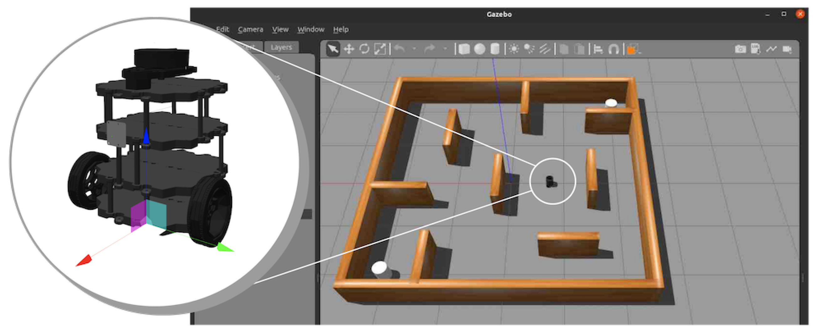
- Links: The two-layer, circular chassis, composed of lightweight Plexiglass, is 30 cm in diameter. Maneuverability and stability are provided by a spherical link of two drive wheels (6.2 cm in diameter and 2 cm in width) plus a caster wheel. Sensor connections have YDLiDAR mounts. Components include the TSA LiDAR, Logitech StreamCam, MPU6050 IMU sensor, and wheels.
- Joints: The components are mounted on the chassis through constant joints to allow rotation, powered by 12V DC motors of 600 RPM. We use fixed joints, securing the LiDAR system (after elevation at 10 cm above the vehicle body) and camera (at 12 cm above the chassis, frontward-facing), and the IMU is placed close to the center of the chassis for high-accuracy orientation measurement.
- Sensors: The YDLiDAR TSA LiDAR is configured with a 360° field of view and a 10 m range, outputting point cloud data through an ROS2 sensor plugin. The Logitech StreamCam, with a field of view of 78° and a resolution of 1080 p, is parameterized with a plugin for a camera to take pictures. The MPU6050 IMU produces output of 6 DOF (accelerometer and gyroscope) and is interfaced as an ROS2 plugin for the IMU. Wheel encoders, at 204 pulses/rev, are defined to produce odometry data via a differential drive plugin.
- Coordinate Frames: The transform tree has base_link as the origin of the vehicle, odom as the odometry tracker, and map as the global frame. Sensor-specific frames (lidar_link, camera_link, imu_link) are defined with offset with respect to base_link so that spatial transformation is correct, and the transformation is published at 50 Hz through tf2.
4.2. Localization and Navigation
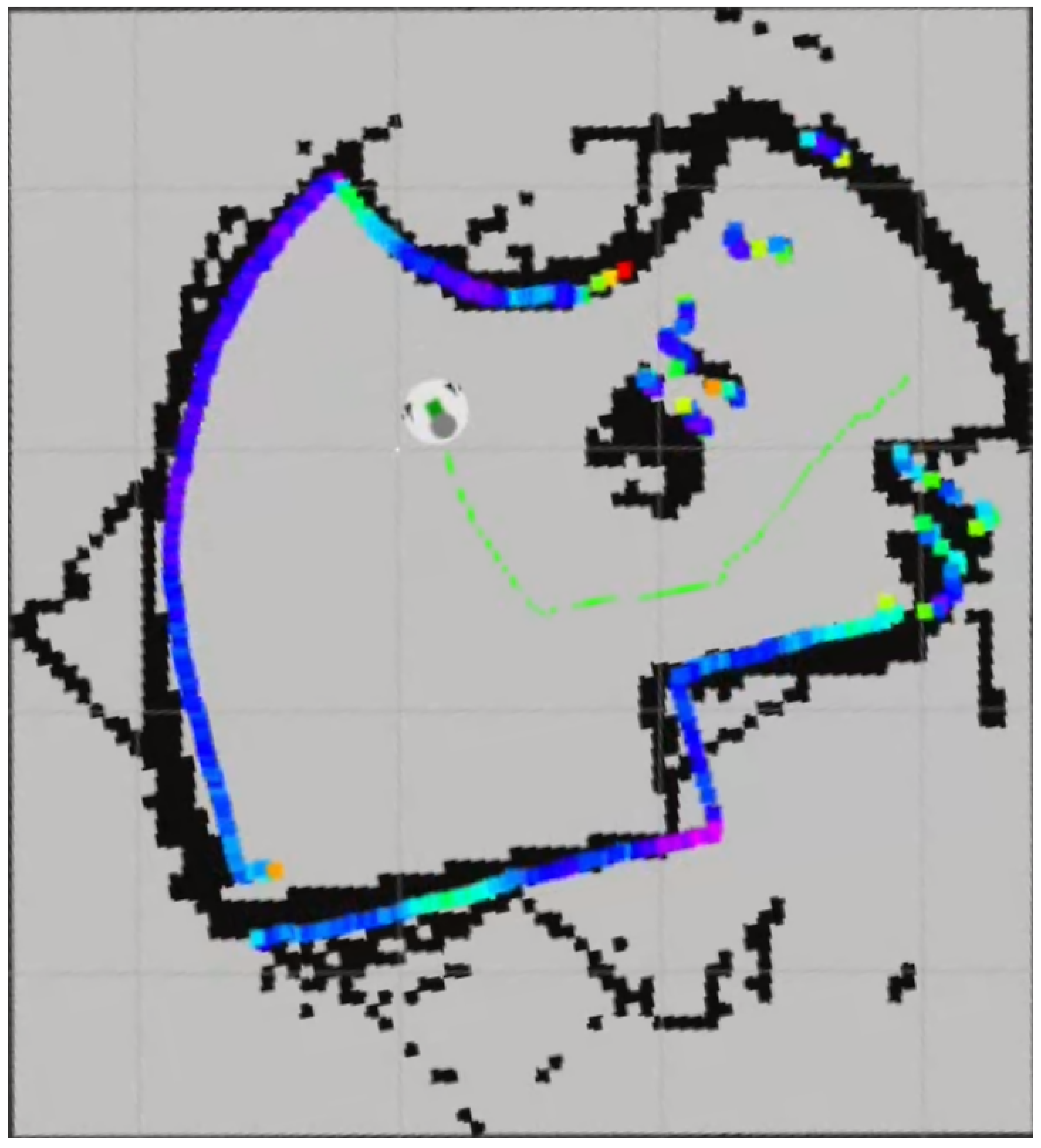
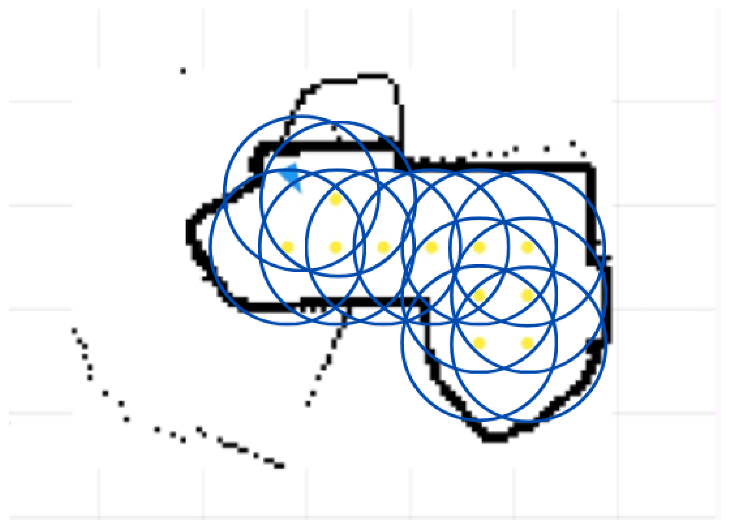
- SLAM: A LiDAR-based 2D SLAM algorithm generates high-resolution occupancy grid maps from streamed data from the YDLiDAR TSA LiDAR, which provides the point cloud data (blue color variation in Figure 6) at 7 Hz with a 360° view angle and 10 m range. Cartographer employs scan matching and loop closure to construct maps at a 0.05 m resolution with a local SLAM window of 5 s and a submap resolution of 0.05 m, being optimized for indoor environments with dynamic obstacles. Generated maps are published onto the ROS2 topic/map for use by the navigation stack
- Localization: Adaptive Monte Carlo Localization (AMCL) provides robust pose estimation by combining data from the YDLiDAR TSA LiDAR, MPU6050 IMU (6-DOF orientation at 100 Hz), and wheel encoders (odometry at 200 Hz, sent at 50 Hz over the ESP32). AMCL runs a particle filter of 2000 particles updated at 10 Hz with a probabilistic motion model motivated by the differential drive kinematics (25 cm wheelbase, with a maximum speed of 0.5 m s−1), yielding a localization error of 0.03 m in real-world tests. The tf2 library also manages the transform tree with coordinate frames (e.g., map, odom, base_link, lidar_link), with transformations published at 50 Hz.
- Global Planning: The NAV2 framework’s global planner computes optimal, collision-free trajectories from the current pose of the robot to meet user-specified goals by employing the A* algorithm. A* acts on a 0.05 m resolution 2D occupancy grid costmap from the Cartographer map (black outline in Figure 6), which the costmap_server updates at 5 Hz. The planner uses a Euclidean distance heuristic, generating paths at a 0.1 m resolution, accounting for the robot’s footprint by scaling up obstacles by 0.2 m for a safety margin. The global path is published onto the ROS2 topic /plan for use as input for local planning.
- Local Planning: The dynamic window approach (DWA) is the sole local planner used by NAV2, evaluating feasible velocity commands within a dynamic window constrained by the robot’s kinematic limits (maximum linear velocity 0.5 m s−1, maximum rotational velocity 1.0 rad s−1), as well as by how closely the robot is positioned to the obstacles. DWA evaluates a sampling of potential velocity commands (linear and rotational) within a dynamic window based on criteria such as how closely the robot approaches obstacles, convergence with the global path, and how much progress the command makes toward the goal. The command that makes the maximum progress while ensuring safety within the environment is chosen. Real-time LiDAR updates the local costmap used as the movement planner around dynamic obstacles.
- Feedback and Monitoring: NAV2 provides mechanisms for providing feedback for the monitoring and debugging of the navigation process.
- ‐
- Path Visualization: The local and global plans are published in RViz2 on the /plan topic, as shown in Figure 6, which allows developers to see the planned path (green line) and identify issues.
- ‐
- Costmap Visualization: Both global and local costmaps are published and portrayed in RViz, including the costs for obstacles, inflation fields, and the robot’s footprint, thereby facilitating the diagnosis of navigation failures in simulations.
- ‐
- Navigation Status: The bt_navigator provides status reporting by means of the /navigate_to_pose action feedback, progress, and current state, as well as several error conditions (e.g., ‘goal unreachable’ errors)
4.3. Object Detection
4.4. Custom Search Algorithm
| Algorithm 1 Grid-Based Search Algorithm |
|
4.5. Motor Control
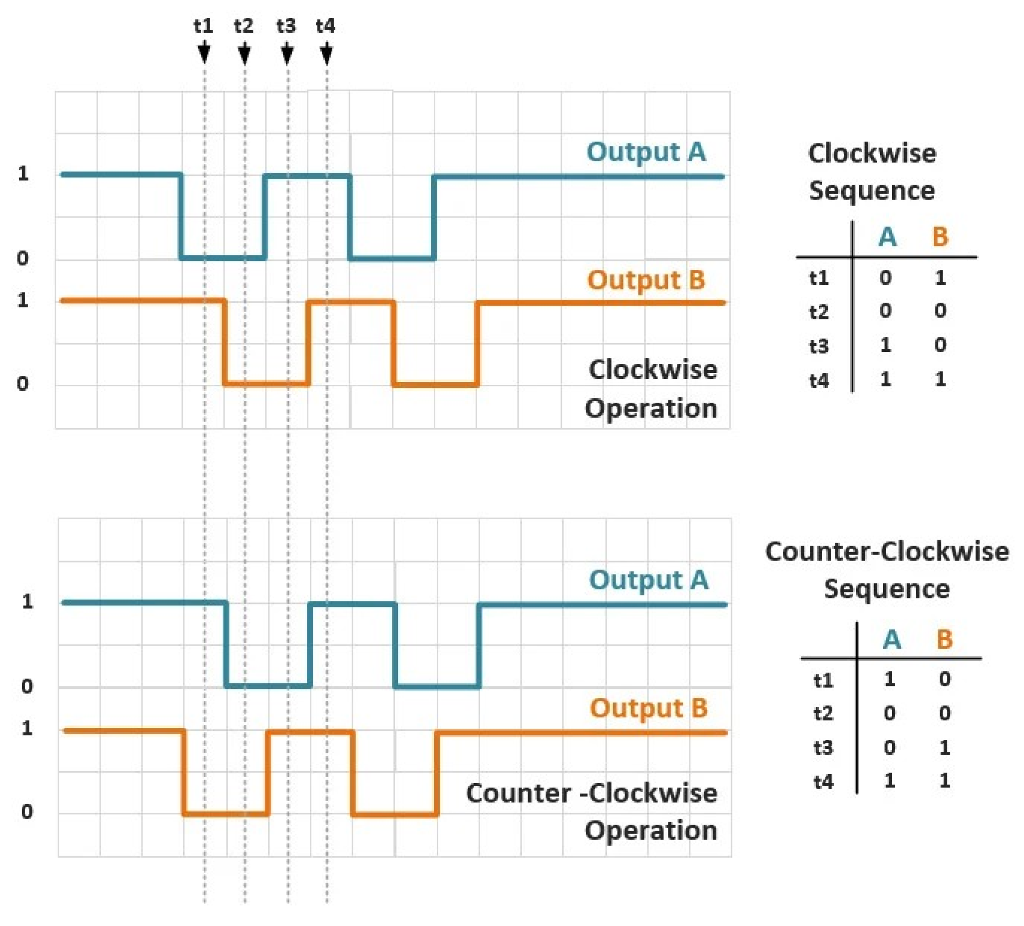
- Quadrature Encoding and Position Tracking: The quadrature encoder offers two signals, A (encA) and B (encB), to monitor the motor’s rotation. They are two waves phase-shifted by each other. Imagine two friends clapping their hands, but one a fraction of a second after the other. This phase shift enables the ESP32 (a very small microcontroller, or a minicomputer) to determine both the speed and direction of turning, as illustrated by Figure 8. The Init routine configures encA and encB as input pins and attaches an interrupt (encoderISR) to encA. An interrupt occurs when there is a state change in encA, so that the system will notice at once rather than continuously checking. This interrupt occurs for any change in encA’s state, so that encoder ticks (small rotational steps) are quickly recognized. The Update routine, prompted by the interrupt, reads encA’s and encB’s states to determine the direction of turning. The direction detection logic is given below.
- ‐
- If encB is high (e.g., “on” or 1) and encA is high, then the wheel rotates clockwise (the direction when turning a clock’s hands to the right).
- ‐
- If encB is high and encA is low (e.g., “off” or 0), the wheel rotates counterclockwise (opposite direction), so the position count decreases by −1.
- ‐
- If encB is low and encA is high, the wheel turns counterclockwise; hence, the position decreases by −1.
- ‐
- If encB is low and encA is low, the wheel turns clockwise; hence, the position increases by +1.
The position variable is the encoder’s cumulative count of ticks, increasing as we turn clockwise and decreasing as we turn counterclockwise, giving a real measurement of the motor’s position. It is analogous to maintaining a bidirectional step count for wheel rotation. - Speed Calculation: The GetfilteredVelocity procedure calculates the motor speed in revolutions per minute (RPM). RPM is the number of complete revolutions per minute that the motor undertakes, similar to the number of turns per minute in which a wheel performs a full revolution. It obtains the current position (GetPosition) by means of a critical region with a mutex (muxMotor) to ensure thread safety. A mutex is similar to a lock on a door—only one process can enter at a time to avoid conflicts when multiple tasks are running simultaneously. The position change () is then calculated by subtracting the previous one from the current one. The time elapsed () in seconds is obtained by the use of micros() (a procedure yielding the time in microsec, being very precise). The initial speed in counts per second (counts/s) is determined by Formula (1):This is converted to RPM using Formula (2):where 204 represents the encoder’s counts per revolution (a parameter specific to this model), and 60 is used to convert s−1 to min−1.
- Low-Pass Filtering for Speed Smoothing: The measured speed is then filtered by a low-pass filter with a cut-off frequency of 25 Hz, thereby reducing measurement noise, and smooth control of the motor speed will be ensured. Here, ’noise’ denotes undesired signal fluctuations like radio static that could occur due to electrical noise or mechanical vibrations. A low-pass filter is similar to a sieve that accepts slow, gradual variations but rejects rapid, jerky variations, providing stable input to the PID controller. The filtering process uses the recursive Equation (3):where is the filtered speed (the smoothed version), v is the current speed (raw measurement), and is the previous speed reading. In this formula, the old filtered value is combined with a fragment of the new data, creating a gradual smoothing effect.
- State Update: The algorithm continually reverts back to the previously noted position, velocity, and time (previousPosition, previousVelocity, previousTime), ensuring continuous speed computation. This process is analogous to a reset operation on a stopwatch, performed after the completion of every lap in preparation for the next one.
4.6. Motor Speed Regulation Process
4.6.1. Manual PID Tuning
- Initializing gains (e.g., Kp = 1.0, Ki = 0.0, Kd = 0.0) and observing the motor’s response while being driven by a setpoint speed (the desired speed).
- Setting Kp until the motor speed was jittery around the setpoint, after which it was reduced by a small amount until a stable steady-state response was achieved. Kp will react to instantaneous errors, e.g., pushing harder if farther away.
- Tuning Ki to decrease the steady-state error (ongoing deviation from the aim) as the motor approached the setpoint over time. Ki is responsible for accumulated errors, such as providing an additional thrust if slow for a while.
- Fine-tuning Kd to dampen oscillations but remaining low enough so as not to enhance noise. Kd takes the rate of change into consideration, such as braking if entering too quickly.
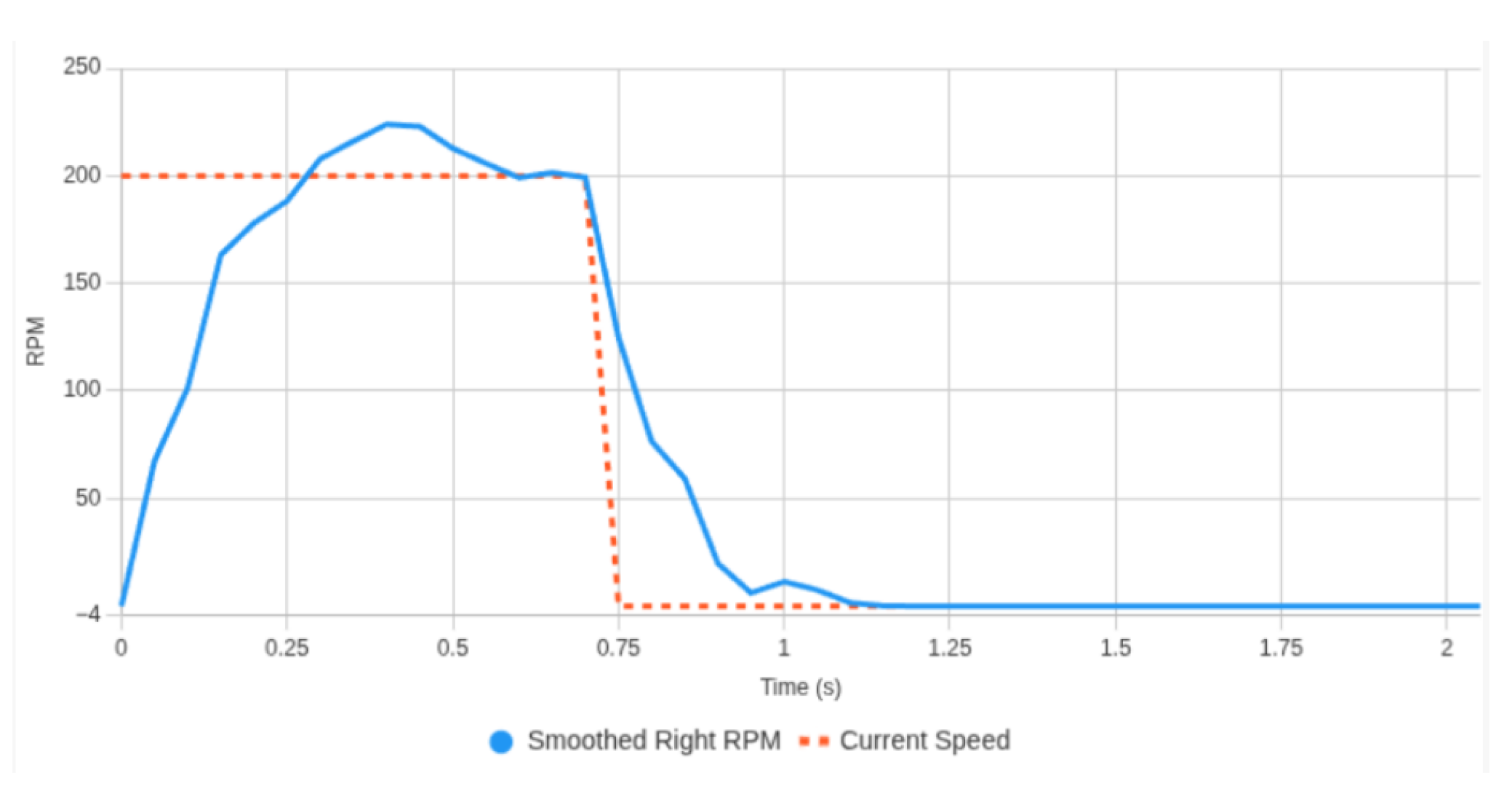
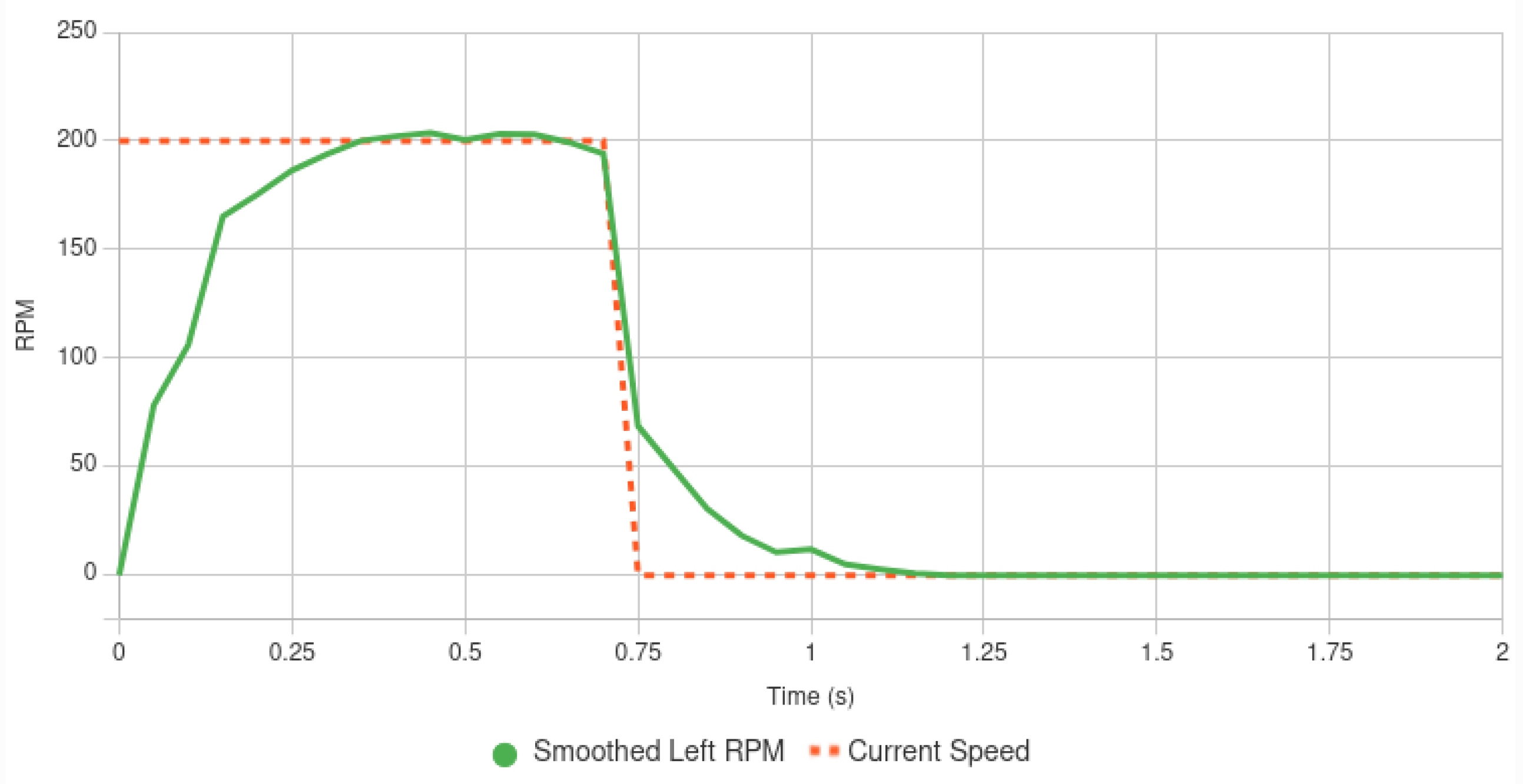
- Overshoot and oscillations, like those observed in the above chart, which will destabilize the robot (rendering the robot jerky or unstable);
- Inconsistencies when in the presence of non-linear motor responses with unpredictable responses or with shifting environmental parameters;
- A labor-intensive tuning process that requires continual fine-tuning for different situations.
4.6.2. Adaptive Fuzzy Logic PID Controller
4.6.3. Selection of Fuzzy Rules
4.6.4. Fuzzy Rule Table
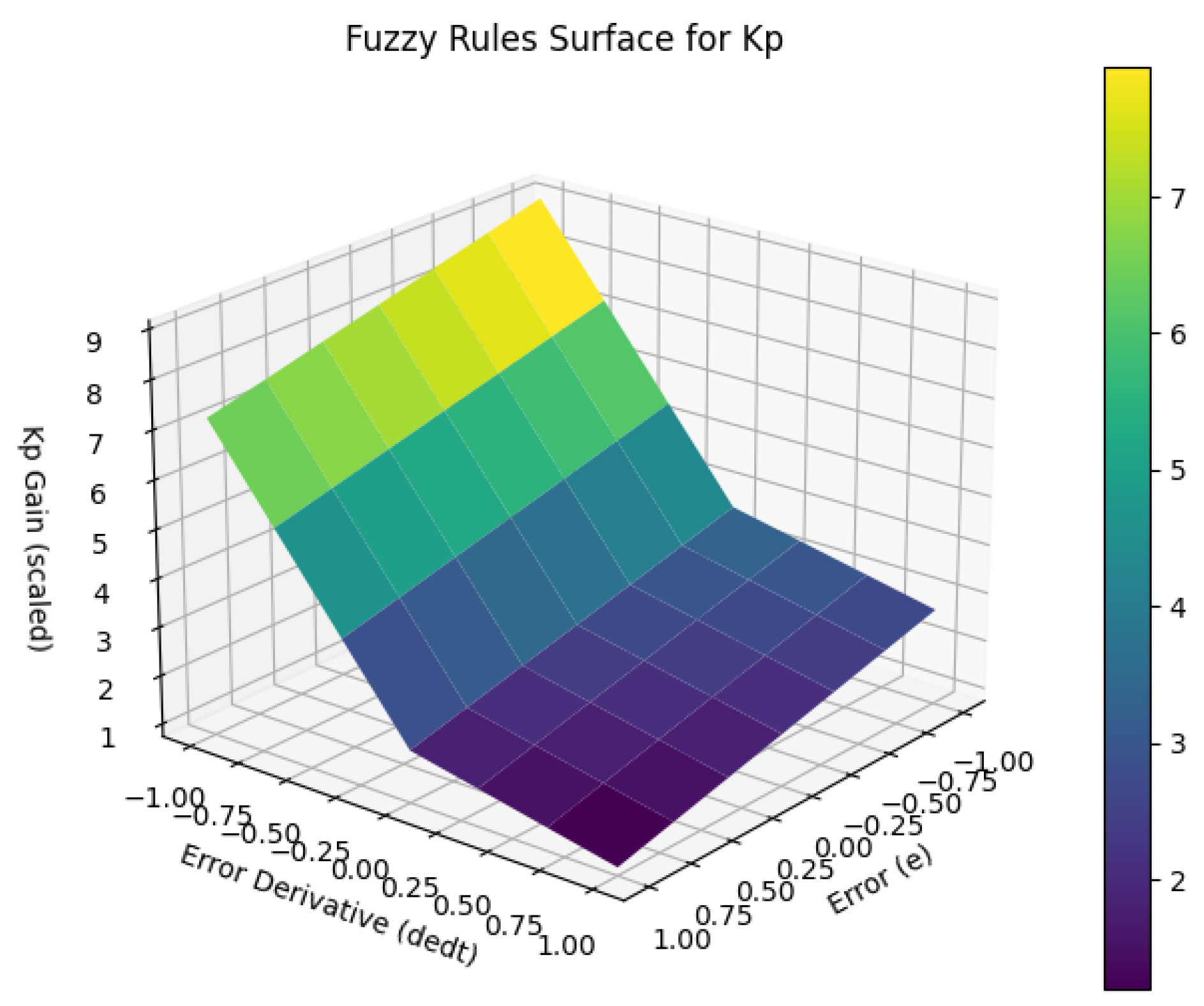
- Rule Table for Kp (× 1.5):
| dedt e | NB | NM | NS | Z | PS | PM | PB |
| NB | 6.0 | 5.8 | 5.6 | 5.4 | 5.2 | 5.0 | 4.8 |
| NM | 4.8 | 4.6 | 4.4 | 4.2 | 4.0 | 3.8 | 3.6 |
| NS | 3.6 | 3.4 | 3.2 | 3.0 | 2.8 | 2.6 | 2.4 |
| Z | 2.4 | 2.2 | 2.0 | 1.8 | 1.6 | 1.4 | 1.2 |
| PS | 2.2 | 2.0 | 1.8 | 1.6 | 1.4 | 1.2 | 1.0 |
| PM | 2.0 | 1.8 | 1.6 | 1.4 | 1.2 | 1.0 | 0.8 |
| PB | 1.8 | 1.6 | 1.4 | 1.2 | 1.0 | 0.8 | 0.6 |
- Rule Table for Ki (× 7.0):
| dedt e | NB | NM | NS | Z | PS | PM | PB |
| NB | 6.0 | 5.8 | 5.6 | 5.4 | 5.2 | 5.0 | 4.8 |
| NM | 4.8 | 4.6 | 4.4 | 4.2 | 4.0 | 3.8 | 3.6 |
| NS | 3.6 | 3.4 | 3.2 | 3.0 | 2.8 | 2.6 | 2.4 |
| Z | 2.4 | 2.2 | 2.0 | 1.8 | 1.6 | 1.4 | 1.2 |
| PS | 2.2 | 2.0 | 1.8 | 1.6 | 1.4 | 1.2 | 1.0 |
| PM | 2.0 | 1.8 | 1.6 | 1.4 | 1.2 | 1.0 | 0.8 |
| PB | 1.8 | 1.6 | 1.4 | 1.2 | 1.0 | 0.8 | 0.6 |
4.6.5. Fuzzy Inference System (FIS) Rules
4.6.6. Implementation Process
- Error Calculation: The ComputeFuzzy method uses error (e) calculation by subtracting the desired setpoint (from ROS 2/cmd_vel, robot’s navigation system command) from the filtered speed (from GetfilteredVelocity). The time difference from the last call is obtained with micros() for appropriate derivative calculation accuracies; there is also a safeguard against division by zero (to prevent mathematical errors).
- Error Derivative Calculation: The derivative of the error (dedt) is computed using Formula (9):This makes the controller capable of responding to rapid speed changes.
- Normalization: To fit the error (e) and error derivative (dedt) to the fuzzy logic system and to allow corner cases like zero or negative setpoints (where the scaling values will be inside the fuzzy “box”), the Map function normalizes them to range from −1.0 to 1.0.
- Membership Calculation: Function calculateMemberships utilizes trapezoidal membership functions (trapezoidalMF) to project the normalized error (e) and error derivative (dedt) into seven fuzzy sets as a representation of each one’s degree of membership of NB.
- Fuzzy Inference: The fuzzy inference mechanism utilizes already defined rules to compute adjusted gains (Kp, Ki, Kd), in which Kd is 0.0.
- PID Computation: The ComputeFuzzy method calculates the control signal using the adjusted gains according to Formula (10):There is anti-windup protection on the integral term and a limit on the output so that it does not saturate (it holds signals within safe ranges).
- Output of Motor Control: The control signal from the L298N motor driver (a chip controlling the direction and speed of the motors) is transmitted to the DC motors, with the PWM signal being changed. The ESP32 adjusts the last error (e) and time before the next iteration.
4.6.7. Results and Performance
4.7. Flutter Application Development
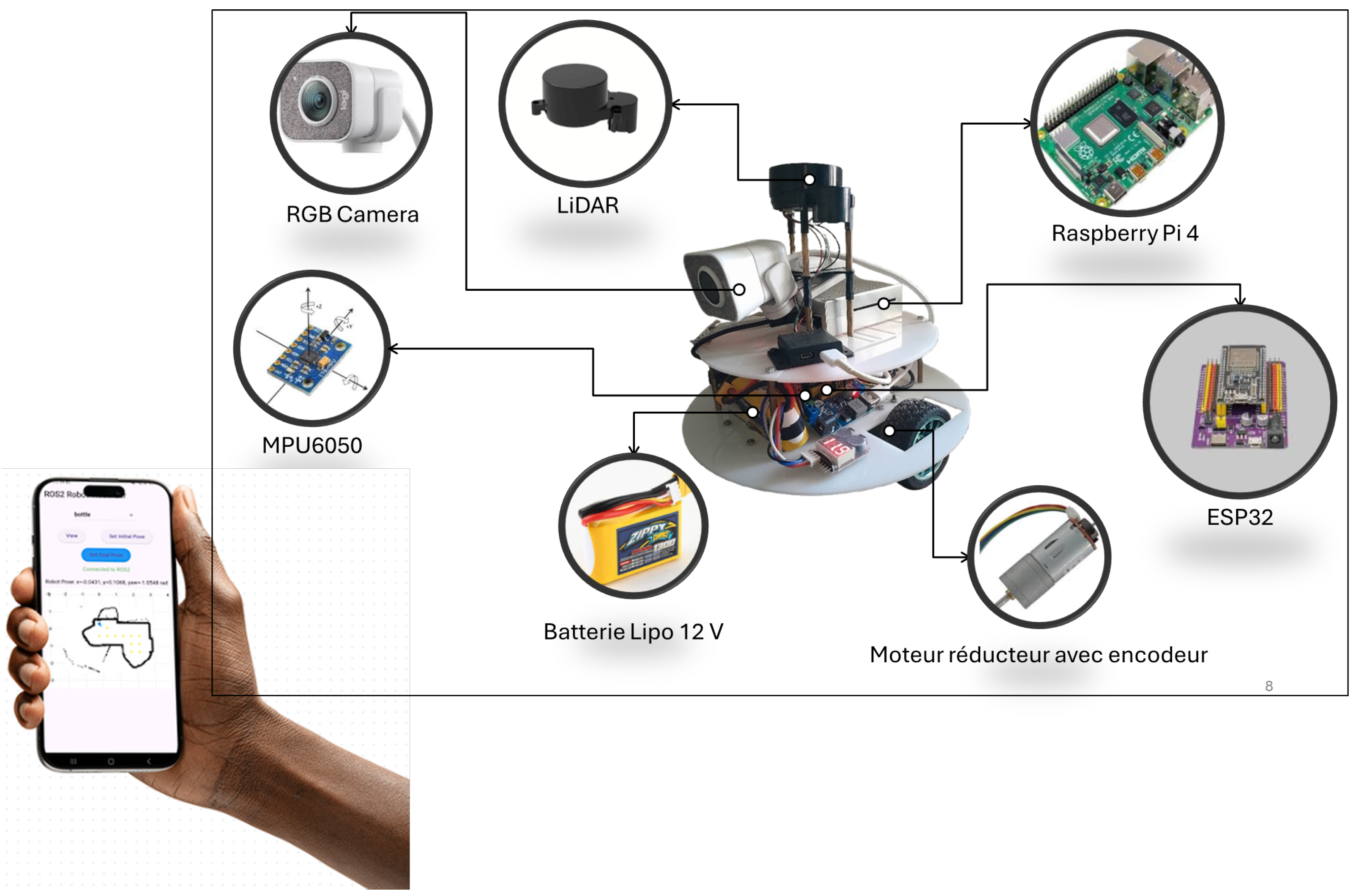
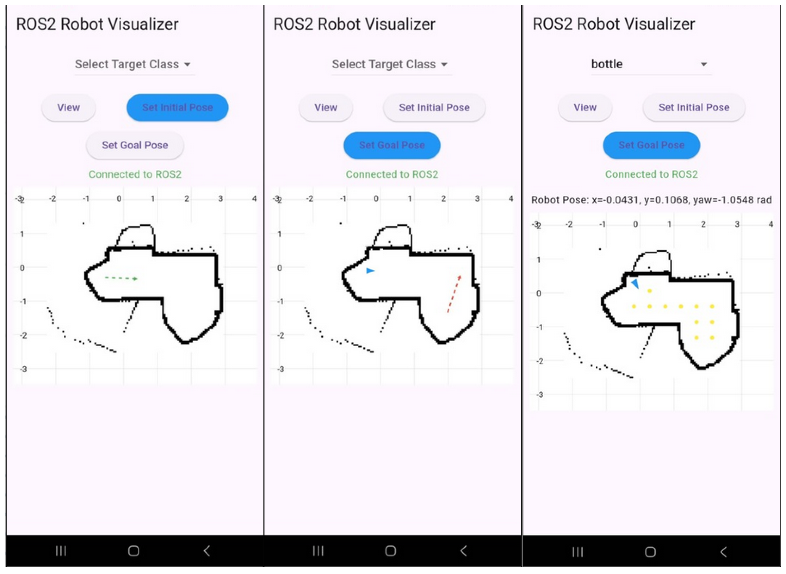
- User Interface Design: The easy-to-understand and user-friendly interface of the app allows users to start tasks (e.g., begin navigating, search objects), see the online status (e.g., current real position), and see the robot’s map. The interface, shown in Figure 13, provides buttons to move the robot in manual mode, provides a view of the map to navigate, and has displays of the status, so users without technical expertise can find it easy to communicate with the robot.
- Task Management: There is a type of task management offered by the software that enables users to assign tasks to the robot, such as initializing the robot position (green arrow), moving to a specific location (red arrow) or beginning an object search. These tasks are then encapsulated in the form of ROS2 commands (e.g., /cmd_vel when dealing with moving) and are transmitted through the WebSocket server. This is similar to providing a robot with a list of tasks that it executes on its own.
- Real-Time Monitoring: The program retrieves the status of the robot and its location information (blue triangle), sensor information, and task accomplishment information like remained waypoints to finish the search task (yellow dots) in real time through ROS2 topics that are subscribed to through WebSocket subscriptions, so that users can view the movement of the robot, such as monitoring a tracked vehicle across a surveyed area.
- ROS2 Integration: The application utilizes an ROS2-WebSocket bridge to enable connectivity with the controller program that is integrated into the robot system. To ensure easy and smooth interactions, this bridge translates application commands into ROS2 syntactic form and then forwards them to the robot.
5. Results and Discussion
5.1. Simulation Tests
5.2. Real-World Tests
5.3. Comparison
6. Conclusions
Author Contributions
Funding
Data Availability Statement
Conflicts of Interest
References
- Keith, R.; La, H.M. Review of Autonomous Mobile Robots for the Warehouse Environment. arXiv 2024, arXiv:2406.08333. [Google Scholar] [CrossRef]
- Gonzalez-Aguirre, J.A.; Osorio-Oliveros, R.; Rodríguez-Hernández, K.L.; Lizárraga-Iturralde, J.; Morales Menendez, R.; Ramírez-Mendoza, R.A.; Ramírez-Moreno, M.A.; Lozoya-Santos, J.d.J. Service Robots: Trends and Technology. Appl. Sci. 2021, 11, 10702. [Google Scholar] [CrossRef]
- Siciliano, B.; Sciavicco, L.; Villani, L.; Oriolo, G. Robotics: Modelling, Planning and Control, 1st ed.; Advanced Textbooks in Control and Signal Processing; Springer: London, UK, 2009; pp. XXIV, 632, eBook ISBN 978-1-84628-642-1/Hardcover ISBN 978-1-84628-641-4/Softcover ISBN: 978-1-84996-634-4. [Google Scholar] [CrossRef]
- Sánchez-Ibáñez, J.R.; Pérez-del Pulgar, C.J.; García-Cerezo, A. Path Planning for Autonomous Mobile Robots: A Review. Sensors 2021, 21, 7898. [Google Scholar] [CrossRef] [PubMed]
- Ishigami, G.; Nagatani, K.; Yoshida, K. Path Planning and Evaluation for Planetary Rovers Based on Dynamic Mobility Index. In Proceedings of the 2011 IEEE/RSJ International Conference on Intelligent Robots and Systems, San Francisco, CA, USA, 25–30 September 2011; pp. 601–606. [Google Scholar] [CrossRef]
- Singh, D.; Trivedi, E.; Sharma, Y.; Niranjan, V. TurtleBot: Design and Hardware Component Selection. In Proceedings of the 2018 International Conference on Computing, Power and Communication Technologies (GUCON), New Delhi, India, 28–29 September 2018; pp. 805–809. [Google Scholar] [CrossRef]
- Robotis. TurtleBot3: Specifications and Performance. Available online: https://www.robotis.us/turtlebot-3/ (accessed on 6 November 2025).
- Clearpath Robotics Jackal UGV: Technical Overview. 2025. Available online: https://clearpathrobotics.com/jackal-small-unmanned-ground-vehicle/ (accessed on 7 October 2025).
- Mobile Manipulation Platform for Autonomous Indoor Inspections in Low-Clearance Areas. In Proceedings of the 25th International Conference on Advanced Vehicle Technologies (AVT), Boston, MA, USA, 20–23 August 2023; Volume 1. [CrossRef]
- NVIDIA Corporation. JetBot: An Open Source AI Robot Platform. 2024. Available online: https://jetbot.org (accessed on 9 October 2025).
- Ramesh, G.; Jeswin, Y.; Rao, D.R.; Suhaag, B.; Uppoor, D.; Kiran Raj, K.M. Real Time Object Detection and Tracking Using SSD Mobilenetv2 on Jetbot GPU. In Proceedings of the 2024 IEEE International Conference on Distributed Computing, VLSI, Electrical Circuits and Robotics (DISCOVER), Mangalore, India, 18–19 October 2024. [Google Scholar] [CrossRef]
- Kawakura, S.; Shibasaki, R. Deep Learning-Based Self-Driving Car: JetBot with NVIDIA AI Board to Deliver Items at Agricultural Workplace with Object-Finding and Avoidance Functions. Eur. J. Agric. Food Sci. 2020, 2, 1–9. [Google Scholar] [CrossRef]
- Pozyx. Industrial Automation: UWB RTLS for Robotics. 2025. Available online: https://www.pozyx.io/solutions/industrial-automation (accessed on 7 October 2025).
- Crețu-Sîrcu, A.L.; Schiøler, H.; Cederholm, J.P.; Sîrcu, I.; Schjørring, A.; Larrad, I.R.; Berardinelli, G.; Madsen, O. Evaluation and Comparison of Ultrasonic and UWB Technology for Indoor Localization in an Industrial Environment. Sensors 2022, 22, 2927. [Google Scholar] [CrossRef] [PubMed]
- Güldenring, R.; Görner, M.; Hendrich, N.; Jacobsen, N.J. Learning Local Planners for Human-aware Navigation in Indoor Environments. In Proceedings of the IEEE/RSJ International Conference on Intelligent Robots and Systems (IROS), Las Vegas, NV, USA, 25–29 October 2020. [Google Scholar] [CrossRef]
- Soheilifar, S. Optimizing MiR100 Performance in Internal Logistics Through Digital Twin-Based Dynamic Speed Adjustment. 2025. Available online: https://webthesis.biblio.polito.it/secure/36032/1/tesi.pdf (accessed on 6 November 2025).
- YDLIDAR. YDLIDAR TSA — 2D LiDAR Product Specifications. Product Datasheet (PDF); Detailed Specs: 0.12–8 m Range, 6 Hz Scan, 0.72° Resolution. Available online: https://www.worldrobotconference.com/uploads/exfile/video/s4tbfh.pdf (accessed on 7 October 2025).
- Hakkim, F.; Rasheed, H.; Varsha, M.C.; Amal, K.A.; Minimol, B. Lidar Based Autonomously Navigating Robot. In Proceedings of the 2024 1st International Conference on Trends in Engineering Systems and Technologies (ICTEST), Kochi, India, 11–13 April 2024; pp. 1–6. [Google Scholar] [CrossRef]
- Sultan, J.M.; Zani, N.H.; Azuani, M.; Yusop, A.M. Analysis of Inertial Measurement Accuracy using Complementary Filter for MPU6050 Sensor. J. Kejuruter. 2022, 34, 959–964. [Google Scholar] [CrossRef]
- Dust, L.J.; Persson, E.; Ekström, M.; Mubeen, S.; Seceleanu, C.; Gu, R. Experimental Evaluation of Callback Behavior in ROS 2 Executors. In Proceedings of the 2023 IEEE 28th International Conference on Emerging Technologies and Factory Automation (ETFA), Sinaia, Romania, 12–15 September 2023; pp. 1–8. [Google Scholar] [CrossRef]
- Open Navigation LLC. Navigation2 (Nav2)—Tutorials and Documentation. 2025. Available online: https://docs.nav2.org/ (accessed on 7 October 2025).
- M J, A.K.; Babu, A.V.; Damodaran, S.; James, R.K.; Murshid, M.; Warrier, T.S. ROS2-Powered Autonomous Navigation for TurtleBot3: Integrating Nav2 Stack in Gazebo, RViz and Real-World Environments. In Proceedings of the 2024 IEEE International Conference on Signal Processing, Informatics, Communication and Energy Systems (SPICES), Kottayam, India, 20–22 September 2024; pp. 1–6. [Google Scholar] [CrossRef]
- Google Cartographer ROS Integration—Documentation. 2022. Available online: https://google-cartographer-ros.readthedocs.io (accessed on 7 October 2025).
- Dwijotomo, A.; Abdul Rahman, M.A.; Mohammed Ariff, M.H.; Zamzuri, H.; Wan Azree, W.M.H. Cartographer SLAM Method for Optimization with an Adaptive Multi-Distance Scan Scheduler. Appl. Sci. 2020, 10, 10347. [Google Scholar] [CrossRef]
- Ultralytics. Model Comparisons (YOLO Family). 2025. Available online: https://www.ultralytics.com (accessed on 7 October 2025).
- Cherubin Szymon, K.W.; Michał, S. YOLO object detection and classification using low-cost mobile robot. Przegląd Elektrotechniczny 2024, 100, 29–33. [Google Scholar] [CrossRef]
- Ultralytics. Quick Start Guide: Raspberry Pi with Ultralytics YOLO11. 2025. Available online: https://docs.ultralytics.com/guides/raspberry-pi/ (accessed on 30 October 2025).
- Alqahtani, D.K.; Cheema, A.; Toosi, A.N. Benchmarking Deep Learning Models for Object Detection on Edge Computing Devices. arXiv 2024, arXiv:2409.16808. [Google Scholar] [CrossRef]
- Kamath, V.; Renuka, A. Performance Analysis of the Pretrained EfficientDet for Real-time Object Detection on Raspberry Pi. In Proceedings of the 2021 International Conference on Circuits, Controls and Communications (CCUBE), Bangalore, India, 23–24 December 2021; pp. 1–6. [Google Scholar] [CrossRef]
- Zagitov, A.; Chebotareva, E.; Toschev, A.; Magid, E. Comparative analysis of neural network models performance on low-power devices for a real-time object detection task. Comput. Opt. 2024, 48, 242–252. [Google Scholar] [CrossRef]
- Cui, J. A search and rescue robot device realization based on ROS operating system combined with visual algorithm. J. Phys. Conf. Ser. 2023, 2492, 012020. [Google Scholar] [CrossRef]
- Nassim, M.; Abdelkader, A. Speed Control of DC Motor Using Fuzzy PID Controller. arXiv 2021, arXiv:2108.05450. [Google Scholar] [CrossRef]
- Boukhary, S.; Colmenares, E. A Clean Approach to Flutter Development through the Flutter Clean Architecture Package. In Proceedings of the 2019 International Conference on Computational Science and Computational Intelligence (CSCI), Las Vegas, NV, USA, 5–7 December 2019; pp. 1115–1120. [Google Scholar] [CrossRef]
- Takaya, K.; Asai, T.; Kroumov, V.; Smarandache, F. Simulation environment for mobile robots testing using ROS and Gazebo. In Proceedings of the 2016 20th International Conference on System Theory, Control and Computing (ICSTCC), Sinaia, Romania, 13–15 October 2016; pp. 96–101. [Google Scholar] [CrossRef]




| Model | Mean Latency (ms) | Throughput (FPS) |
|---|---|---|
| YOLO11-Small (YOLO11s) [27] | 300–1200 | 0.8–3.3 |
| YOLOv8-Nano (YOLOv8n) [28] | 400–700 | 1.4–2.5 |
| EfficientDet-Lite0 (TFLite, INT8) [29,30] | 50–150 | 6–20 |
| Faster R-CNN (ResNet-50 + FPN) [30] | 2000–6000 | <0.5 |
| SSD MobileNet v1 (TFLite, INT8) [28] | ≈209 | ≈4.8 |
| The proposed model | 100–300 | 3.5–10 |
| Robot | Navigation Success Rate (%) | Positional Error (cm) | Weight (kg) | Cost (USD) | Object Detection Accuracy (%) | Latency (ms) |
|---|---|---|---|---|---|---|
| TurtleBot3 [7] | 94 | 3 * | 1 | 1800 | N/A | 120 * |
| Clearpath Jackal [8] | 96 | 5 * | 17 | 15,000+ | N/A | 80 * |
| MiR100 [15] | 97 | 3 * | 70 | 20,000+ | 92 * | 50 |
| NVIDIA JetBot [11] | 69.0 | 8 * | 0.8 * | 250 | 85 | 150 * |
| Proposed robot | 95 | 3 | 1.4 | 369 | 95 | 120 |
Disclaimer/Publisher’s Note: The statements, opinions and data contained in all publications are solely those of the individual author(s) and contributor(s) and not of MDPI and/or the editor(s). MDPI and/or the editor(s) disclaim responsibility for any injury to people or property resulting from any ideas, methods, instructions or products referred to in the content. |
© 2025 by the authors. Licensee MDPI, Basel, Switzerland. This article is an open access article distributed under the terms and conditions of the Creative Commons Attribution (CC BY) license (https://creativecommons.org/licenses/by/4.0/).
Share and Cite
Gargouri, A.; Karray, M.; Zalila, B.; Ksantini, M. Design and Development of an Autonomous Mobile Robot for Unstructured Indoor Environments. Machines 2025, 13, 1044. https://doi.org/10.3390/machines13111044
Gargouri A, Karray M, Zalila B, Ksantini M. Design and Development of an Autonomous Mobile Robot for Unstructured Indoor Environments. Machines. 2025; 13(11):1044. https://doi.org/10.3390/machines13111044
Chicago/Turabian StyleGargouri, Ameur, Mohamed Karray, Bechir Zalila, and Mohamed Ksantini. 2025. "Design and Development of an Autonomous Mobile Robot for Unstructured Indoor Environments" Machines 13, no. 11: 1044. https://doi.org/10.3390/machines13111044
APA StyleGargouri, A., Karray, M., Zalila, B., & Ksantini, M. (2025). Design and Development of an Autonomous Mobile Robot for Unstructured Indoor Environments. Machines, 13(11), 1044. https://doi.org/10.3390/machines13111044


