Abstract
Traditional manufacturing methods of wind tunnel nozzles are often cumbersome, time-consuming, and costly. The study of spinning forming technology for wind tunnel nozzles provides a pathway to improve manufacturing efficiency while reducing both cost and production cycle. However, when processing alloy steel (20MnMo), challenges arise due to large deformation, high-temperature loading, and complex wall-thickness control. To address these issues, this work proposes a die-less multi-pass hot spinning process. A three-dimensional dynamic explicit finite element model was developed to simulate the stress–strain evolution during multi-pass spinning. In the first pass, an L9 orthogonal experimental design was applied to analyze the influence of spinning parameters on forming stress and plastic deformation capacity, thereby determining the optimal combination of workpiece rotation speed, axial feed, and radial feed rates. The optimized design strategy was subsequently extended to ten passes. Based on simulation results, hot spinning experiments were conducted, followed by precision machining of the nozzle’s inner and outer surfaces. Inspection results indicated that the deviations in contour and wall thickness between simulation predictions and actual specimens were both less than 0.5%. This study establishes an integrated process route combining numerical simulation, hot spinning, and finishing, providing both theoretical support and practical guidance for the high-precision and high-stability manufacturing of complex thin-walled nozzle structures.
1. Introduction
As a critical component in aerospace applications, aerodynamic experiments, and high-speed flow control systems, the wind tunnel nozzle plays a decisive role in determining airflow acceleration capacity and boundary layer development behavior, thereby directly influencing the accuracy and repeatability of experimental results [1,2,3]. Under supersonic or high-Reynolds-number conditions, the nozzle must possess a highly continuous and smooth internal streamline structure to achieve an ideal isentropic expansion process and maintain a stable laminar flow field [4,5]. However, due to the dramatic variation in cross-sectional geometry along the axial direction, the large structural length, and the complex distribution of wall thickness, conventional machining methods such as CNC milling, electrical discharge machining, or welded assembly are often unable to balance geometric accuracy, structural strength, thermal stability, and manufacturing efficiency. In particular, for medium- and large-scale wind tunnel tests, extremely stringent requirements are imposed on dimensional stability, inner surface roughness, and overall concentricity of the nozzle, which further exacerbates the challenges in manufacturing.
In recent years, metal spinning has emerged as an efficient and high-precision plastic forming process, demonstrating unique advantages in the fabrication of thin-walled rotational components [6,7,8]. Keneshlou et al. [9] proposed a novel approach for spinning non-circular blanks by employing octagonal blanks made of AL-1050, taking anisotropy into account. Through experimental studies and numerical simulations, they investigated deviations in spring back and strain distribution of the formed parts compared with ideal geometries. Chen et al. [10] examined the evolution of micro-structure in ellipsoidal heads under different spinning parameters, and their results indicated that proper control of forming angle, inter-pass angle, and feed rate could improve microstructural uniformity, thereby providing theoretical support for process optimization. Lin et al. [11] addressed the dimensional control challenge of thin-walled ellipsoidal heads with large diameter-to-thickness ratios by proposing a two-step edge-constrained die-less spinning process, which effectively eliminated wrinkling and improved forming accuracy. Zhu et al. [12] developed an edge-constrained die-less spinning method with an enlarged bottom allowance to suppress instability during the forming of thin-walled circular blanks, successfully achieving high-precision forming of large straight-wall aluminum alloy domes. Imamura et al. [13] introduced a die-less hot spinning process for near-net forming of Ti-6Al-4V sheets, further revealing that shear, bending, and torsional loads coexist during hot spinning. This finding highlights the complex multi-mode coupled deformation mechanisms involved, offering theoretical guidance for high-precision spinning.
Many scholars have also developed various finite element (FE) models of the spinning process, with simulation studies primarily focusing on key issues such as wall-thickness variation, stress–strain evolution, temperature distribution, and material flow characteristics, gradually establishing a systematic theoretical framework. Roy et al. [14] investigated the influence of axial feed rate on the shape and wall-thickness variation in hemispherical parts in die-less tube spinning. Three types of FE models—axisymmetric, shell-element, and solid-element models—were constructed, and the results indicated that the axisymmetric model is suitable for preliminary process design, while the solid-element model is more appropriate for detailed optimization. Jawale et al. [15] established an FEM model to analyze the stress distribution and strain path in die-less spinning, and validated the model accuracy through spinning force experiments. Their findings revealed that the stress distribution characteristics in die-less spinning differ significantly from those in conventional spinning, although the wrinkling mechanisms remain similar, providing theoretical guidance for subsequent process path optimization. Wang et al. [16] developed a reliable FE model to improve the closing spinning quality of plunger-type parts, and validated the model with spinning force experimental data. The results showed strong agreement between the simulation predictions and experimental measurements, confirming the model’s accuracy. Sedighi et al. [17] established a three-dimensional explicit FE model to analyze strain distribution during hot die-less spinning of thick-walled aluminum alloy tubes, revealing pronounced circumferential compressive strain characteristics and free-end effects. Experimental results further demonstrated that this process enhanced the average mate-rial hardness by 18%, indicating a significant strengthening effect. Sangkharat et al. [18] conducted a systematic study on the influence of spinning parameters on forming force and wall thickness through experiments combined with three-dimensional FE simulations and Taguchi design, enabling defect prediction and process optimization. Based on the FORGE software (https://www.transvalor.com/en/forge, accessed on 3 October 2025), a three-dimensional FE model of the CRS process was also developed, with a particular focus on key modeling challenges such as mesh design, material constitutive behavior, and friction conditions. A moving local fine-mesh strategy was introduced around the roller, which ensured simulation accuracy while significantly improving computational efficiency [19].
The hot spinning process of wind tunnel nozzles involves large deformation, elevated temperature, and multi-pass loading. During forming, the material undergoes nonuniform plastic flow in both axial and radial directions, and wall-thickness control is highly sensitive to process parameters. Owing to the continuous contraction from the large to the small diameter, load transfer becomes complex, and the stress–strain distribution varies dramatically, often leading to localized deformation, wall thinning, or spring back, which ultimately affect geometric accuracy and structural stability. Therefore, this study for the first time applies the die-less multi-pass hot spinning technique to high-strength 20MnMo steel, extending the material applicability of this process. The 20MnMo steel exhibits high flow stress, low ductility, and pronounced temperature–strain-rate sensitivity, which are significantly different from those of aluminum or titanium alloys and impose stricter requirements on path planning, thermal management, and interfacial friction control.
To address these forming challenges, a progressive local reduction strategy combining multi-segment deformation with incremental approximation to the throat section is proposed to achieve coordinated control of geometric accuracy and wall-thickness convergence. Meanwhile, a fully coupled three-dimensional explicit finite element model is developed based on the Johnson–Cook thermoplastic constitutive relationship and temperature-dependent coupling characteristics. Through the sequential transfer of equivalent strain and temperature fields across ten spinning passes, the model enables integrated optimization of the process path and parameters. This research establishes a closed-loop “material–process–simulation” framework, providing new theoretical support and technological routes for the high-precision forming of complex thin-walled components made of high-strength steels.
2. Analysis of the Spinning Process for Wind Tunnel Nozzles
2.1. Structural Characteristics of the Spun Wind Tunnel Nozzle
The wind tunnel nozzle exhibits an overall axisymmetric geometry, continuously composed of a convergent section, a throat, and a divergent section, as illustrated in Figure 1. It is characterized by sharp variations in contour curvature, a long axial length, and a high thickness-to-diameter ratio [20]. While these features are essential for ensuring aerodynamic performance, they also significantly increase the difficulty of forming and manufacturing. In particular, the transition regions between the convergent and divergent sections, as well as the small-diameter throat area, are prone to wall-thickness thinning, local wrinkling, and even fracture. Therefore, prior to spinning process design, it is necessary to clearly define the geometric dimensions and technical specifications of the nozzle workpiece. These parameters serve as the basis for billet design and forming path planning. The key dimensions of the wind tunnel nozzle are listed in Table 1.
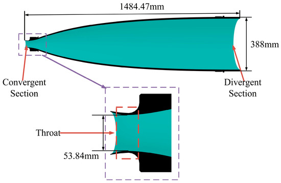
Figure 1.
Structural configuration of the wind tunnel nozzle.

Table 1.
Key geometric parameters of the wind tunnel nozzle.
To meet the forming requirements of the complex nozzle structure, an integral seamless hollow cylindrical billet was designed as the initial workpiece, as shown in Figure 2. The forming material is 20MnMo alloy steel, in which manganese (Mn) enhances the strength and hardness, while molybdenum (Mo) improves high-temperature performance and tempering stability. The initial dimensions are listed in Table 2, and the chemical composition is given in Table 3, the material properties are listed in Table 4. This configuration ensures symmetric and stable loading during the spinning process and provides sufficient material allowance for radial deformation in both the converging and expanding sections. The integral billet design offers good process adaptability and a reasonable wall-thickness distribution, while reserving enough allowance for subsequent machining and performance testing, demonstrating excellent engineering feasibility [21].

Figure 2.
Structural configuration of the billet.

Table 2.
Dimensional parameters of the billet.

Table 3.
Chemical composition of 20MnMo alloy steel (wt.%).

Table 4.
Mechanical properties of 20MnMo alloy steel.
In this study, the die-less hot spinning process is employed as an efficient forming approach. By applying multi-pass localized loading under elevated temperature conditions, gradual plastic accumulation and progressive contour approximation of the material are achieved, effectively avoiding common issues in conventional manufacturing methods such as assembly errors, surface damage, and non-uniform forming [22,23]. This process enables high-precision control of the nozzle’s external geometry and satisfies the dual requirements of geometric accuracy and mechanical performance under large deformation conditions.
2.2. Finite Element Modeling and Simulation Method of the Spun Wind Tunnel Nozzle
The die-less hot spinning process was modeled and numerically simulated using the ABAQUS/Explicit finite element platform to systematically analyze the influence of process parameters on the forming quality of the nozzle [24]. The model accounts for the thermo-mechanical coupling behavior of the material at elevated temperatures by employing the Johnson–Cook thermo-viscoplastic constitutive model, as listed in Table 5 [25], and incorporates time-dependent contact heat transfer and frictional heat generation mechanisms to more accurately capture the local stress–strain evolution and temperature field distribution during the spinning process.

Table 5.
Johnson-Cook model variables of 20MnMo material.
In this study, the explicit dynamic method was employed. The explicit approach determines the solution by advancing the motion state from one time increment to the next. At the beginning of an increment (t), the governing equation of dynamic equilibrium can be expressed as [26]:
The nodal acceleration ü is obtained from the following equation:
where M denotes the nodal mass matrix, P represents the external loads applied to the nodes, and I is the vector of internal forces generated within the elements.
To update the nodal velocity over time, the central difference method was employed for time integration. Assuming that the acceleration remains constant within a single time step, the change in velocity can be calculated from Equation (3).
In practical analyses, it is usually infeasible to perform quasi-static simulations directly on a real-time scale, since the required computational time would be excessively long. To improve computational efficiency, the mass scaling technique is commonly employed. In this study, a mass scaling factor of 1000 was applied.
A three-dimensional dynamic explicit finite element model was established in the FEM environment to simulate the spinning process, as shown in Figure 3. The billet material was assumed to be homogeneous and isotropic. A total of 236,250 hexahedral elements (C3D8R) were employed, and the mesh distribution is illustrated in Figure 4. The plastic behavior of the material was modeled using the von Mises yield criterion combined with isotropic strain hardening [27]. In this study, the effects of strain-rate hardening and temperature dependence were neglected. Contact was defined using the penalty method, and Coulomb friction with a coefficient of 0.2 was adopted to simulate the interaction between the billet and the spinning roller. The roller trajectory is shown in Figure 5.
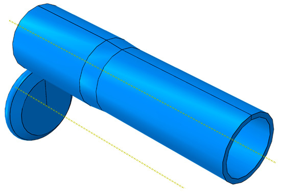
Figure 3.
3D FEM model of the spun wind tunnel nozzle.
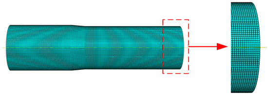
Figure 4.
Finite element mesh of the spun wind tunnel nozzle.
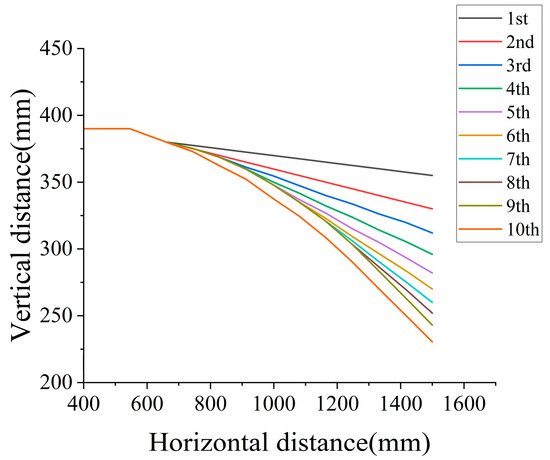
Figure 5.
Roller trajectory during the spinning process.
2.3. Simulation Process Parameter Setup for the Spun Wind Tunnel Nozzle
The wind tunnel nozzle was formed using a die-less spinning process. In this method, by controlling the roller path, feed rate, and reduction force, the cylindrical billet was gradually necked along the axial direction under elevated temperature conditions, thereby achieving high-precision forming of a continuous and smooth inner contour of the nozzle. The overall process consisted of billet pretreatment, hot spinning, and natural cooling. The key process parameters included spindle speed, roller feed rate, roller fillet radius, reduction depth, and spinning temperature. In this study, ten-pass heavy hot spinning simulations were carried out, with the processing parameters summarized in Table 6. The roller trajectory is illustrated in Figure 5, while the billet material employed was 20MnMo alloy steel. A schematic diagram of the spinning process is shown in Figure 6.

Table 6.
Spinning parameters used in the simulation.
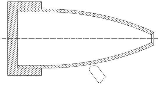
Figure 6.
Schematic diagram of the hot spinning process.
3. Spinning Process Parameter Design and Forming Characteristics of Wind Tunnel Nozzles
3.1. Analysis of Hot Spinning Process Parameters for the Wind Tunnel Nozzle
During the necking spinning process, the diameter undergoes significant variation accompanied by a complex three-dimensional stress–strain state, making the plastic flow behavior of the material highly sensitive to process parameters. Improper parameter selection may easily lead to defects such as cracking, instability, or wall-thickness nonuniformity, thereby compromising the forming accuracy and service reliability of thin-walled nozzle components. Therefore, it is essential to employ scientific experimental design methods to quantitatively analyze the main process variables, in order to clarify their influence on forming loads and material deformation behavior. This provides the theoretical foundation for parameter optimization and process stability control. In this study, process parameters were systematically explored at each forming pass to identify the optimal settings.
To clarify the rationale for process parameter selection, three key parameters—spindle speed, axial feed rate, and radial feed rate—were chosen, as these factors were identified in preliminary experiments and simulation studies as the dominant variables affecting deformation behavior. Spindle speed determines the rate of frictional heat generation and influences the degree of material thermal softening. Axial feed rate controls the continuity of material flow along the axial direction, directly affecting strain accumulation and wall-thickness convergence. Radial feed rate regulates the intensity of localized deformation and plays a critical role in achieving stable forming while preventing excessive thinning.
Therefore, the orthogonal experimental design was established using these three parameters for optimization, the factor–level table is shown in Table 7. By analyzing the distributions of stress, strain, and temperature under different parameter levels, an optimal combination was obtained that balances formability, dimensional accuracy, and deformation uniformity, thereby ensuring the stability of the multi-pass hot spinning process.

Table 7.
Factor level design of spinning process parameters.
To reduce the number of experiments and effectively investigate the combined effects of various factors and their levels, an L9 (33) orthogonal array was employed to design nine groups of process parameter combinations. Finite element numerical simulations were then conducted to obtain the maximum equivalent stress (σmax) and maximum equivalent plastic strain (εmax) corresponding to each combination, which were used as response indicators to characterize the forming load and deformation capacity of the component. The experimental design and results are summarized in Table 8.

Table 8.
Results of the L9 orthogonal experiments.
Based on the orthogonal experimental results of the first-pass necking spinning, it can be concluded that the process parameters exert a significant influence on both forming load and plastic deformation. Among the tested combinations, the parameter set of spindle speed 150 rpm, axial feed rate 135 mm/min, and radial feed rate 2.75 mm/min effectively reduced the maximum equivalent stress (468.41 MPa) while maintaining a reasonable equivalent plastic strain (2.79). This achieved an optimal balance between suppressing the risk of forming cracks and ensuring sufficient plastic flow of the material. Therefore, this parameter combination can be regarded as the preferred scheme for the first-pass necking spinning, providing a reference for parameter transition and overall optimization in subsequent multi-pass forming. Similarly, the remaining nine passes were also analyzed using the same orthogonal approach to determine their respective optimal process parameters; however, the detailed data and procedures are not reiterated here and are only applied and validated in the context of overall process optimization.
3.2. Optimized Process Parameters for the Wind Tunnel Nozzle Spinning
Based on the preceding orthogonal experimental analysis and finite element simulation results, the optimal process parameters for Passes 1–10 were systematically summarized, covering key variables including workpiece temperature, spindle speed, axial feed rate, and radial feed rate. The results are presented in Table 9. This table not only provides a clear reference for parameter transition across the multi-pass forming sequence, but also reveals an evolutionary pattern of the spinning process characterized by constant high temperature, progressively increasing spindle speed, and gradually decreasing feed rates.

Table 9.
Optimized Results of Spinning Parameters.
3.3. Stress and Strain Distribution in the Spinning Process of the Wind Tunnel Nozzle
During the first spinning pass, the nozzle exhibits significant stress and strain concentration, as shown in Figure 7. The main deformation occurs in the roller contact zone and the middle-to-rear section of the necking area, where intense plastic flow takes place. The equivalent plastic strain increases progressively along the axial direction, indicating a gradual forming characteristic. This pass achieves effective preforming; however, the stress distribution remains non-uniform, and further optimization of the trajectory and parameters is needed to improve wall-thickness uniformity. The stress values shown in the figures are expressed in megapascals (MPa).

Figure 7.
Stress and strain contour maps of the first pass: (a) stress; (b) strain.
During the second spinning pass, the plastic deformation of the workpiece intensified, and the stress–strain distribution range expanded, as shown in Figure 8. Significant stress concentration occurred in the roller–workpiece contact region and at the end of the necking section, where the material maintained a high-strength flow state. Compared with the first pass, the stress distribution became broader and smoother, while the strain increased continuously along the axial direction, consistent with the characteristics of the externally applied loading.

Figure 8.
Stress and strain contour maps of the second pass: (a) stress; (b) strain.
During the third spinning pass, the stress and strain within the workpiece continued to accumulate and gradually reached a stable state, as shown in Figure 9. The roller contact region and the end of the necking section remained the primary areas of stress concentration, where the material yielded and entered a steady deformation stage. The equivalent plastic strain further increased, extending both axially and radially with a more uniform distribution. This pass enhanced strain accumulation in the forming zone and achieved better coordination between stress and strain.

Figure 9.
Stress and strain contour maps of the third pass: (a) stress; (b) strain.
During the fourth spinning pass, the stress and strain of the workpiece further evolved, exhibiting a distinct multi-pass accumulation behavior, as shown in Figure 10. The equivalent stress was mainly concentrated in the roller contact region and the small-end necking area, with a more uniform distribution compared with the previous pass. The equivalent plastic strain continued to increase and extended along the axial direction, while the outer radial layer exhibited higher strain than the inner layer.

Figure 10.
Stress and strain contour maps of the fourth pass: (a) stress; (b) strain.
During the fifth spinning pass, the deformation of the workpiece tended to stabilize, primarily serving to control the small-end contour and achieve dimensional convergence, as shown in Figure 11. The equivalent stress remained concentrated in the roller contact region and around the small-end area, indicating that the material was still undergoing high-intensity plastic deformation. The overall stress distribution became uniform. The equivalent plastic strain slightly decreased compared with the previous pass, with higher strain observed in the outer layer than in the inner layer, reflecting an outward-to-inward loading characteristic.

Figure 11.
Stress and strain contour maps of the fifth pass: (a) stress; (b) strain.
During the sixth spinning pass, the stress and strain of the workpiece exhibited pronounced regional concentration, as shown in Figure 12. The equivalent stress was mainly concentrated in the necking section and the roller contact region, reflecting the characteristics of localized loading. The plastic strain was primarily distributed in the throat transition zone and the final necking area, indicating that material flow was concentrated within the regions of intense deformation.

Figure 12.
Stress and strain contour maps of the sixth pass: (a) stress; (b) strain.
During the seventh spinning pass, the deformation of the workpiece became more stable, primarily serving to refine the small-end contour and adjust residual stresses, as shown in Figure 13. The equivalent stress was concentrated in the outer layer of the small-end region, while it significantly decreased in other areas. The strain was confined to the outer layer near the small-end tip, exhibiting a gentle gradient that ensured the final geometric accuracy and structural stability.

Figure 13.
Stress and strain contour maps of the seventh pass: (a) stress; (b) strain.
During the eighth spinning pass, the overall deformation of the workpiece was essentially completed, entering a stable fine-tuning stage, as shown in Figure 14. High stress was concentrated in the outer layer at the small-end tip. This pass primarily focused on strain harmonization and boundary transition, accomplishing the final shaping of the small-end region and the release of residual stresses.

Figure 14.
Stress and strain contour maps of the eighth pass: (a) stress; (b) strain.
During the ninth spinning pass, the process primarily served to compact the final contour and coordinate residual stresses, as shown in Figure 15. The equivalent stress was concentrated in the outer layer of the small-end region. The deformation zone was confined to the edge of the small end, with limited axial and radial expansion, ensuring the final geometry of the nozzle and effective control of residual stresses.

Figure 15.
Stress and strain contour maps of the ninth pass: (a) stress; (b) strain.
During the tenth spinning pass, the workpiece reached its final forming stage, primarily focusing on contour finishing and residual stress coordination, as shown in Figure 16. High stress was concentrated in the outer layer and outlet region of the small end, serving to compact the end section and refine the overall contour.

Figure 16.
Stress and strain contour maps of the tenth pass: (a) stress; (b) strain.
Finite element analysis of the 1st–10th spinning passes reveals the stress–strain evolution law of the nozzle during the multi-pass necking process. The overall deformation can be divided into four stages: initial concentration, progressive accumulation, coordinated transition, and final stabilization. In the initial stage (Passes 1–3), stress is concentrated in the roller contact region, where the material undergoes intense plastic deformation, and the strain extends along both the axial and radial directions. During the accumulation stage (Passes 4–6), the range of stress and strain expands with a more uniform distribution, promoting wall-thickness convergence and contour refinement. In the transition stage (Passes 7–8), deformation tends to stabilize, focusing on local contour adjustment and residual stress coordination. Finally, in the stabilization stage (Passes 9–10), stress and strain converge and become uniformly distributed, completing the compaction and precision control of the small-end region.
It can be seen that during the multi-pass spinning process of the nozzle, the stress–strain evolution exhibits a progressive transition from concentration to homogenization and from accumulation to refinement. This pattern reveals the fundamental mechanical nature of the spinning process and demonstrates that a well-designed multi-pass forming path can effectively control wall thickness and improve geometric accuracy, thereby providing both theoretical and technological foundations for the high-quality forming of complex thin-walled structures.
4. Manufacturing Process and Results of Spun Wind Tunnel Nozzle
4.1. Hot Spinning Stage of the Wind Tunnel Nozzle
During the hot spinning stage, the workpiece was uniformly heated using a resistance furnace. To ensure temperature uniformity, the billet was held in the furnace for 30 min prior to spinning, allowing the temperature distribution to stabilize. Throughout the forming process, the surface temperature of the workpiece was continuously monitored in real time using thermocouples and an infrared pyrometer, and maintained within the range of 950 ± 10 °C. When the temperature deviated from the target value, the heating power was automatically adjusted to ensure a constant forming temperature.
Figure 17a shows the initial state of the workpiece and equipment before spinning. As the roller progressively applied localized deformation in successive passes, the metal underwent significant plastic flow under localized loading, enabling gradual diameter reduction and a rational redistribution of wall thickness along the convergent section. Figure 17b illustrates the hot spinning process of the nozzle. The workpiece was heated by the flame to a high-temperature range of 900–1000 °C, achieving an ideal plastic state. Under the localized loading of the roller, the material experienced plastic flow and progressively formed the convergent section. This process clearly demonstrates the forming mechanism of hot spinning, characterized by localized loading and progressive shaping, in which multiple small deformations under elevated temperatures are accumulated to achieve precise control of both the overall geometry and wall thickness distribution.
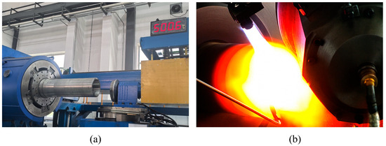
Figure 17.
Hot spinning process of the wind tunnel nozzle: (a) before hot spinning; (b) during hot spinning.
4.2. Machining Stage of the Spun Wind Tunnel Nozzle
After turning and precision finishing, the geometric deviations of the workpiece are effectively corrected, and the dimensional accuracy at critical locations is significantly improved. The inner wall surface roughness meets the stringent aerodynamic requirements of the nozzle. A comparison between the post-machining and as-formed geometries indicates that the machining process not only enhances the surface quality but also ensures the final forming precision of the overall structure to a large extent.
Figure 18a shows the machining of the outer surface of the spun nozzle, while Figure 18b illustrates the finishing of the inner surface.
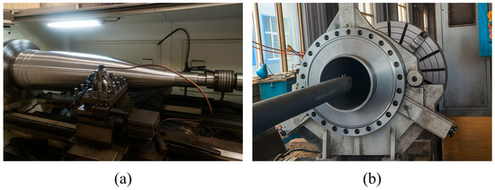
Figure 18.
Machining of the spun nozzle: (a) outer surface turning; (b) inner surface finishing.
4.3. Comparative Analysis of Wall Thickness and Contour Evolution
To verify the accuracy and applicability of the finite element model for the hot spinning process, the experimentally measured nozzle geometry and wall-thickness distribution were compared with the simulation predictions. By analyzing the external and internal contours as well as the axial evolution of wall thickness, the predictive capability of the model in representing geometric forming and material flow behavior during complex deformation was evaluated. The geometrical dimensions and key diameters were measured using a coordinate measuring machine (CMM) with an accuracy of ±2 μm. Each set of process parameters was tested three times, and the average value was taken as the final result. The standard deviation was calculated to assess repeatability, which was found to be less than 0.3%. The average deviation between the simulation and experimental results was less than 0.5%. The main sources of error include measurement accuracy, thermal expansion effects, material property variation, and sample clamping error, all of which were minimized through calibration and environmental control.
Figure 19 presents the overlapped contour comparison between the experimental specimen and the finite element simulation prediction. As can be observed, across the entire axial range, both the outer and inner surface profiles show good agreement between the simulation and the experimental measurements. In particular, within the necking section, the predicted contour curves closely match the experimental results in terms of shape variation, curvature distribution, and transition trend during contraction. This demonstrates the high accuracy and feasibility of the employed forming path planning strategy and mandrel-free deformation control method, providing a reliable foundation for subsequent process optimization.
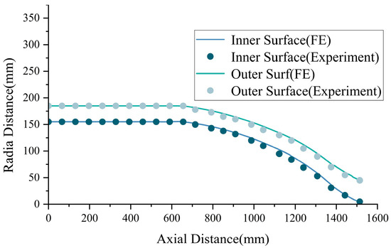
Figure 19.
Comparison of nozzle contours between experiment and simulation.
Figure 20 illustrates the comparison of wall thickness evolution along the axial direction between the experimental measurements and finite element simulation results. As shown, the overall trend of the wall thickness distribution exhibits a high degree of consistency, indicating that the simulation model possesses strong predictive capability in capturing material migration behavior in both axial and radial directions. Furthermore, the simulation data closely track the experimental wall thickness variation across the entire axial span, with deviations well controlled within a small range. This further confirms the reliability and practical applicability of the developed thermal spinning finite element model in predicting deformation depth and wall thickness evolution.
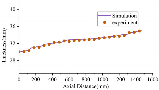
Figure 20.
Comparison of nozzle wall thickness between experiment and simulation.
Based on the combined analysis of Figure 19 and Figure 20, the simulation model demonstrates high accuracy not only in predicting the geometric contour but also in capturing the wall thickness variation trend. This verifies its effectiveness as a reliable tool for investigating the thermal spinning process of wind tunnel nozzles and optimizing corresponding process parameters. The model effectively reflects the multi-pass deformation behavior and material plastic flow characteristics, thus providing a robust numerical foundation for subsequent path optimization and structural performance improvement.
Despite the overall good agreement, localized deviations still exist, primarily concentrated in the converging region of the small-end contour and the deformation transition zone. The main causes may include the following: the simulation adopts an idealized constant friction coefficient, while in the actual spinning process, the friction state fluctuates with temperature rise, material hardening, and lubrication condition; the simulation model uses a fitted stress–strain curve for 20MnMo, whereas slight variations exist between different material batches; minor vibrations and transmission lags in the spinning machine during loading may lead to slight deviations of the actual roller trajectory from the planned path; especially in regions with sharp curvature transitions at the small end, there may be systematic errors caused by probe contact measurements and ultrasonic echo identification.
5. Conclusions
This study investigated the mandrel-free multi-pass hot spinning process of a 20MnMo alloy steel wind-tunnel nozzle through a combination of finite element simulation and experimental validation. The main conclusions are as follows:
- (1)
- A three-dimensional explicit finite element model was established in ABAQUS to successfully simulate the multi-pass hot spinning process of the nozzle. The results reveal four distinct stages—initial concentration, progressive accumulation, coordinated transition, and final stabilization—which elucidate the characteristic deformation evolution of nozzle spinning.
- (2)
- Based on orthogonal experimental design and finite element analysis, spindle speed, axial feed rate, and radial feed rate were identified as the key factors affecting forming stress and plastic flow behavior. An optimized process strategy featuring constant temperature, increasing spindle speed, and decreasing feed rate was proposed, which significantly improved stress distribution and wall-thickness uniformity. Quantitative results show that the wall-thickness deviation decreased from 0.42 mm to 0.08 mm, the strain dispersion was reduced by approximately 75%, and the average deviation between simulation and experiment was less than 0.5%, confirming the accuracy and reliability of the proposed model and parameter optimization scheme.
- (3)
- Multi-pass hot spinning experiments conducted under the optimized parameters demonstrated that the proposed method enables high-precision forming of the nozzle’s geometry and wall-thickness distribution with stable deformation and no observable defects.
The results confirm the feasibility and engineering applicability of the mandrel-free hot spinning technique for manufacturing complex thin-walled nozzles made of high-strength steel. Compared with traditional machining and welding methods, this process significantly improves forming efficiency, reduces manufacturing costs, and ensures structural integrity, providing an important reference for the integrated fabrication of large-scale aerospace nozzles.
Author Contributions
P.L., thesis conceptualization and first draft writing. L.S., thesis supervision. Z.L., financial support. W.L., experimental design. Z.J., literature review and survey. X.T., simulation and analysis. Q.G., data processing. S.G., figures preparation. All authors have read and agreed to the published version of the manuscript.
Funding
This work was financially supported by XXX Technology for Large-Scale Wind Tunnel Experiments (JCKY2023205XXX). Due to confidentiality requirements of the funding agreement, both the full project name and grant number cannot be disclosed publicly.
Data Availability Statement
Data are contained within the article.
Conflicts of Interest
The authors declare no conflicts of interest.
References
- Matsunaga, M.; Fujio, C.; Ogawa, H.; Higa, Y.; Handa, T. Nozzle design optimization for supersonic wind tunnel by using surrogate-assisted evolutionary algorithms. Aerosp. Sci. Technol. 2022, 130, 107879. [Google Scholar] [CrossRef]
- Shen, J.; Dong, J.; Li, R.; Zhang, J.; Chen, X.; Qin, Y.; Ma, H. Integrated supersonic wind tunnel nozzle. Chin. J. Aeronaut. 2019, 32, 2422–2432. [Google Scholar] [CrossRef]
- Sabnis, K.; Babinsky, H.; Galbraith, D.S.; Benek, J.A. Nozzle geometry-induced vortices in supersonic wind tunnels. AIAA J. 2021, 59, 1087–1098. [Google Scholar] [CrossRef]
- Li, L.; Zhu, H.; Maryami, R.; Zhang, X.; Liu, Y. Flow and acoustic characterization of turbulence grids at wind tunnel nozzle exit. J. Sound Vib. 2024, 590, 118535. [Google Scholar] [CrossRef]
- Arshad, A.; Samarasinghe, S.; Kovalcuks, V. A simplified design approach for high-speed wind tunnels. Part-II: Optimized design of settling chamber and inlet nozzle. In Proceedings of the 2020 11th International Conference on Mechanical and Aerospace Engineering (ICMAE), Athens, Greece, 14–17 July 2020; IEEE: New York, NY, USA, 2020; pp. 150–154. [Google Scholar]
- Russo, I.M.; Cleaver, C.J.; Allwood, J.M. Seven principles of toolpath design in conventional metal spinning. J. Mater. Process. Technol. 2021, 294, 117131. [Google Scholar] [CrossRef]
- Polyblank, J.A.; Allwood, J.M. Parametric toolpath design in metal spinning. CIRP Ann. 2015, 64, 301–304. [Google Scholar] [CrossRef]
- Gondo, S.; Arai, H.; Kajino, S.; Hanada, K. Evolution of texture distribution in thickness direction of aluminum sheet in metal spinning. Mater. Charact. 2022, 188, 111877. [Google Scholar] [CrossRef]
- Keneshlou, M.; Biglari, F.R.; Shafaie, M. A numerical and experimental analysis of noncircular blank spinning. J. Manuf. Process. 2023, 94, 159–182. [Google Scholar] [CrossRef]
- Chen, J.Y.; Lin, Y.C.; Pang, G.D.; Li, X.-H. Effects of spinning parameters on microstructures of ellipsoidal heads during marginal-restraint mandrel-free spinning. Adv. Manuf. 2020, 8, 457–472. [Google Scholar] [CrossRef]
- Lin, Y.C.; Chen, J.Y.; He, D.G.; Li, X.-H.; Yang, J. Marginal-restraint mandrel-free spinning process for thin-walled ellipsoidal heads. Adv. Manuf. 2020, 8, 189–203. [Google Scholar] [CrossRef]
- Zhu, L.; Huang, C.; Li, X.; Chang, X.; Li, Y. Research on marginal-restraint mandrel-free spinning of large thin-walled aluminum alloy domes with large bottom reserves. Int. J. Adv. Manuf. Technol. 2024, 133, 3843–3858. [Google Scholar] [CrossRef]
- Imamura, Y.; Ikawa, K.; Motoyama, K.; Iwasaki, H.; Hirakawa, T.; Utsunomiya, H. Deformation characteristics of Ti-6Al-4V plate in mandrel-free hot spinning. Procedia Manuf. 2018, 15, 1207–1214. [Google Scholar] [CrossRef]
- Roy, B.K.; Korkolis, Y.P.; Arai, Y.; Araki, W.; Iijima, T.; Kouyama, J. A study of forming of thin-walled hemispheres by mandrel-free spinning of commercially pure aluminum tubes. J. Manuf. Process. 2021, 64, 306–322. [Google Scholar] [CrossRef]
- Jawale, K.; Loukaides, E.G. An investigation of mandrel-free spinning. Procedia Manuf. 2019, 29, 145–152. [Google Scholar] [CrossRef]
- Wang, Y.; Su, H.; Lu, G.; Dai, J.; Zhao, B.; Dai, C.; Fu, Y. Quality prediction of plunger components based on the finite element method during the neck-spinning process. Int. J. Adv. Manuf. Technol. 2020, 106, 1509–1520. [Google Scholar] [CrossRef]
- Sedighi, M.; Jalili, I.; Kasaeian-Naeini, M. Experimental study and FEM analysis of forward hot dieless spinning. Mech. Ind. 2018, 19, 404. [Google Scholar] [CrossRef]
- Sangkharat, T.; Dechjarern, S. Spinning process design using finite element analysis and Taguchi method. Procedia Eng. 2017, 207, 1713–1718. [Google Scholar] [CrossRef]
- Zhang, D.; Li, F.; Li, S.; Zhao, S. Finite element modeling of counter-roller spinning for large-sized aluminum alloy cylindrical parts. Front. Mech. Eng. 2019, 14, 351–357. [Google Scholar] [CrossRef]
- Lakebrink, M.T.; Bowcutt, K.G.; Winfree, T.; Huffman, C.C.; Juliano, T.J. Optimization of a Mach-6 quiet wind-tunnel nozzle. J. Spacecr. Rocket. 2018, 55, 315–321. [Google Scholar] [CrossRef]
- Imamura, Y.; Ikawa, K.; Sakane, Y.; Iwasaki, H.; Hirakawa, T. Investigation of forming accuracy in mandrel-free hot-spinning. Procedia Eng. 2017, 207, 1701–1706. [Google Scholar] [CrossRef]
- Gao, P.; Yu, C.; Fu, M.; Xing, L.; Zhan, M.; Guo, J. Formability enhancement in hot spinning of titanium alloy thin-walled tube via prediction and control of ductile fracture. Chin. J. Aeronaut. 2022, 35, 320–331. [Google Scholar] [CrossRef]
- Jing, Z.; Fan, J.; Liu, X.; Song, Y.; Wang, Z.; Cao, K.; Chen, Y.; Fu, H.; Zhang, J.; Li, J. EBSD analysis of grain boundary evolution and dynamic recrystallization of Inconel 625 superalloy at various hot spinning feed rates. Prog. Nat. Sci. Mater. Int. 2024, 34, 56–65. [Google Scholar] [CrossRef]
- Wang, Y.; Su, H.; Qian, N.; Liu, K.; Dai, J.; Zhao, Z.; Ding, W. Neck-spinning quality analysis and optimization of process parameters for plunger components: Simulation and experimental study. Chin. J. Aeronaut. 2021, 34, 174–191. [Google Scholar] [CrossRef]
- Sirigiri, V.K.R.; Gudiga, V.Y.; Gattu, U.S.; Suneesh, G.; Buddaraju, K.M. A review on Johnson Cook material model. Mater. Today Proc. 2022, 62, 3450–3456. [Google Scholar] [CrossRef]
- Wang, L.; Long, H. Investigation of material deformation in multi-pass conventional metal spinning. Mater. Des. 2011, 32, 2891–2899. [Google Scholar] [CrossRef]
- Gondo, S.; Arai, H.; Kajino, S.; Nakano, S. Evolution of strain state of a rolled aluminum sheet in multi-pass conventional spinning. J. Manuf. Sci. Eng. 2021, 143, 061011. [Google Scholar] [CrossRef]
Disclaimer/Publisher’s Note: The statements, opinions and data contained in all publications are solely those of the individual author(s) and contributor(s) and not of MDPI and/or the editor(s). MDPI and/or the editor(s) disclaim responsibility for any injury to people or property resulting from any ideas, methods, instructions or products referred to in the content. |
© 2025 by the authors. Licensee MDPI, Basel, Switzerland. This article is an open access article distributed under the terms and conditions of the Creative Commons Attribution (CC BY) license (https://creativecommons.org/licenses/by/4.0/).