Article

Enabling Manual Guidance in High-Payload Industrial Robots for Flexible Manufacturing Applications in Large Workspaces

by
Paolo Avanzi La Grotta
,
Martina Salami
,
Andrea Trentadue
,
Pietro Bilancia
* and
Marcello Pellicciari
Department of Sciences and Methods for Engineering, University of Modena and Reggio Emilia, Via Amendola 2, 42122 Reggio Emilia, Italy
*
Author to whom correspondence should be addressed.
Machines 2025, 13(11), 1016; https://doi.org/10.3390/machines13111016
Submission received: 9 October 2025 / Revised: 27 October 2025 / Accepted: 30 October 2025 / Published: 3 November 2025

Abstract

Industrial Robots (IRs) are typically employed as flexible machines to perform many types of repetitive and intensive tasks within fenced safe areas, ensuring high productivity and cost efficiency. However, their rigid programming approaches often pose challenges during cell commissioning and reset, hindering the implementation of self-reconfigurable systems. In addition, several production lines still need the presence of skilled operators to conduct assisted assembly operations and inspections. This motivates the growing interest in the development of innovative solutions for supporting safe and efficient human–robot collaborative applications. The manual guidance of the IR end-effector is a representative functionality of such collaboration, as it simplifies heavy-part manipulation and allows intuitive robot teaching and programming. The present study reports a sensor-based approach for enabling manual guidance operations with high-payload IRs and discusses its practical implementation on a production cell with an extended workspace. The setup features a KUKA robot mounted on a custom linear track actuated via Beckhoff technology to enable flexible assembly and machining operations. The developed logic and its software configuration, split into multiple control units to allow the manual guiding of both the 6-axis IR and the linear track unit, are described in detail. Finally, an experimental demonstration involving two users with different levels of expertise was conducted to evaluate the approach during target teaching on a physical cell. The results showed that the proposed manual guidance method significantly reduced task completion time by more than 55% compared with the conventional teach pendant, demonstrating the effectiveness and practical advantages of the developed framework.

1. Introduction

In today’s competitive market, the demand for small-batch production of customized products is growing rapidly. Manufacturers must adapt to this trend by ensuring that their production systems are highly flexible and capable of handling frequent changes in production programs and schedules [1,2]. Driven by these requirements, the adoption of Industrial Robots (IRs) has increased over the past decade, with global installations exceeding 500,000 units per year in the 2020–2024 period according to the International Federation of Robotics [3], representing more than double the figure recorded ten years earlier. Nevertheless, while IRs inherently offer significant architectural flexibility due to their programmable nature and wide range of motion, their deployment is often constrained by rigid programming methodologies. As a result, they often face challenges adapting quickly to changes, limiting their effectiveness in dynamic manufacturing environments [4,5].
Despite the considerable advancements made in robot offline programming tools in the last decade, which allow operators to simulate robot operations and generate near-ready code with minimal debugging, challenges remain in the commissioning and calibration phases of extended robotic systems. Discrepancies between virtual models and real-world setups often necessitate manual adjustments, introducing inefficiencies and extending the commissioning process [6]. This limitation highlights the necessity for more intuitive and accessible robot programming methods and tools, allowing also industrial operators with limited expertise to commission and reconfigure physical assets with minimal effort [7,8]. Such tools must allow IRs to be seamlessly integrated into new workflows, ensuring that production lines can be updated efficiently without extensive downtime or specialized expertise [9].
Collaborative robots have demonstrated the value of manual guidance (usually referred to as hand-guiding) as an intuitive programming method to teach points or execute tasks by manually positioning the robot [10,11]. By enabling users to move the robot easily and record procedures that can be automatically replicated, hand-guiding offers a user-friendly programming mode that eliminates the need for advanced programming expertise [12]. This capability, however, has largely been confined to low-payload robots and constrained workspaces. In contrast, traditional high-payload IRs, which are widely used in large manufacturing environments, still rely heavily on online programming via teach pendants [13]. This conventional approach often leads to inefficiencies, prolonged downtime, and limited adaptability to dynamic production demands [14]. Extending hand-guiding functionality to this class of robots could revolutionize their application across various tasks, including [15,16]:
  • Teaching poses for complex paths or assembly operations: Operators could guide an IR to precise locations for welding, painting, or machining tasks, eliminating the need for extensive manual programming through teach pendants [17,18].
  • Lifting and manipulating heavy objects: In industries such as automotive and aerospace, IRs with hand-guiding capabilities could assist in handling bulky components like engine parts, wings, or fuselage sections, reducing operator strain and increasing throughput [19].
  • Collaborative assembly tasks: IRs equipped with hand-guiding functionality can enhance human–robot collaboration during assembly processes, such as positioning heavy components while human workers perform fine-tuning tasks or quality checks [20,21].
Early studies [22] first demonstrated the feasibility of manually guiding industrial manipulators using force/torque sensing, showing that intuitive, pendant-free programming was possible. Later research focused on enhancing safety and interaction quality [23], proposing adaptive admittance control for smooth and compliant motion, while other works [24] extended this approach to higher-payload robots through an admittance-based control scheme managing contact forces. Despite these advances, existing studies largely address low- to medium-payload systems and do not consider scalability to heavy-duty robots or extended workspaces requiring additional kinematic axes. Commercial manual-guidance solutions are also available for certain industrial and high-payload collaborative robots. For example, Comau Aura [25] integrates torque and proximity sensors to enable safe hand-guiding with medium–high payloads, while FANUC offers a hand guidance option for its standard manipulators [26], allowing pendant-free teaching through an external force/torque sensor. These examples confirm that manual guidance is both feasible and industrially relevant. However, existing implementations are proprietary, limited in configurability, and not extensible to multi-axis or high-payload systems.
The introduction of hand-guiding to high-payload IRs also necessitates thorough consideration of safety requirements [27]. Unlike collaborative robots, which are designed with inherent safety features like force monitoring and impedance control, traditional IRs operate at high speeds and forces, posing significant risks in shared workspaces. Implementing manual guidance in these systems requires additional layers of safety [28], i.e.:
  • Sensor integration: Force and torque sensors are essential to detect operator inputs and ensure the robot responds adaptively to manual guidance. Vision systems may also be employed to monitor the workspace for potential collisions.
  • Safety-rated control systems: The robot control architecture must support safety-rated functionalities, such as monitored stops, safe speed limits, and power/force limiting, to ensure compliance with standards like ISO 10218 [29] and ISO/TS 15066 [30].
  • Workspace operational zoning: Defining safe zones and implementing virtual barriers can help manage the interaction between humans and robots, particularly in dynamic manufacturing environments.
  • Risk assessments and certifications: Comprehensive risk assessments must be conducted to identify potential hazards and implement mitigation strategies. Certification processes ensure that the system meets industry safety standards.
Previous research has explored hand-guiding functionalities in IRs adopting either sensor-less or sensor-based approaches. These studies have provided valuable theoretical insights into control architectures and sensor integration but often lack practical implementation details, failing to address challenges encountered during real-world deployment or to provide actionable guidelines for practitioners. Sensor-less approaches involve monitoring and controlling processes without utilizing direct feedback from physical sensors [31,32,33]. These techniques rely on indirect measurements, algorithms, and models to infer necessary information. In contrast, sensor-based approaches directly gather data through physical sensors, enabling real-time feedback on various parameters such as force, torque, and position. This direct feedback allows robots to perform more precise and adaptable tasks, with modern IRs integrating Force/Torque (F/T) sensors for efficient operation management [34,35,36,37]. However, sensor-based systems require calibration and necessitate robot controllers that support real-time external interfaces.
In this context, the present paper proposes an approach to enable manual guidance in high-payload IRs operating in extended workspaces [38]. This work advances the existing literature by providing a detailed methodology and clear implementation steps for practical applications. The main novel contributions are:
  • Extending manual guidance to robotic cells with large workspaces by integrating control of a 6-Degrees-of-Freedom (DoF) serial IR and an additional custom designed linear track positioner (1-DoF).
  • Providing an in-depth description of the proposed framework, detailing all experimental practices needed to establish logical connections between different control systems.
  • Validation and demonstration on a physical prototype, delivering practical insights and deployment guidelines. The utilized setup includes a high-payload KUKA IR featuring the Robot Sensor Interface (RSI) software package [39] and utilizes the Beckhoff automation technology for the actuation of the additional linear axis.
The applied methodology streamlines human–robot interaction by significantly reducing programming cycle time and simplifying the acquisition of robot targets necessary during automated production cycles. The goal is to develop an easy-to-use approach that enables seamless control of a high-payload IR, overcoming technological constraints typically encountered during the robot teaching process.
The remainder of the paper is organized as follows: Section 2 presents an overview of the adopted approach, detailing the programmed operational modes and the setup configuration. Section 3 describes the mathematical model integrated into the manual guidance logic and discusses its practical implementation. Section 4 focuses on the final validation conducted on the physical robotic cell. At last, Section 5 provides the concluding remarks.

2. Approach Overview

The proposed framework is tailored for robotic cells featuring IRs operating in extended workspaces. It specifically addresses setups incorporating linear tracks to enhance the robot reach, enabling flexible and precise manipulation across large areas [38]. The cell considered in this work, depicted in Figure 1, includes a KUKA KR210 R2700 Prime robot mounted on linear track system with 4.3 m of strokes actuated via Beckhoff technology. The cell has a footprint of 9 m × 5 m, as shown in Figure 1c, and is primarily dedicated to assembly and deburring processes. To support these operations, it is equipped with a tool storage system housing a variety of tools for component handling and manufacturing tasks, a stationary spindle, and a pick-up station, providing versatility and adaptability for diverse applications. The specifications of all these components are detailed in Table 1.
The conceived manual guidance system allows operators to easily move the robot and teach targets (e.g., for precisely engaging the tools during pick-and-place operations in the storage, as shown in Figure 1b), streamlining cell calibration and commissioning. It employs a sensor-based approach by integrating an F/T sensor at the robot’s end-effector, positioned directly above the tool changer device [8]. This configuration ensures precise measurement of the external forces ( F x , F y , F z , M x , M y , M z ), expressed in the sensor frame shown in Figure 2. The force signals are processed by the Schunk NetBox unit, which amplifies and converts the strain-gauge outputs into digital form. The processed data is then streamed via Ethernet to the Beckhoff CX5140 Programmable Logic Controller (PLC) at a fixed rate of 1 ms. At the PLC level, the digital force and torque values are made available to the dedicated control module for real-time computation but also transmitted to the KUKA KRC4 controller via EtherCAT, enabling the execution of two operation modes for hand-guiding the 7-DoF robotic platform (Figure 2):
(a)
Linear Track Guidance (1-DoF): The robot remains fixed in its last pose while the linear track moves to reposition the robot along the Y-direction of the robot base frame. The real-time control loop runs on the PLC, which generates and sends position commands to the Beckhoff AX8118 servo drives that operate the servomotors actuating the linear axis. This mode allows the operator to move the robot along the cell and teach positions along the linear track. It should be noted that in this operation mode, the robot controller remains in a passive state, while the PLC receives from the EtherCAT network the orientation data of the end-effector (A, B, C angles) provided by the robot controller, which is required to correctly compute the current rotation matrix and correctly interpret the force data sampled with the F/T sensor.
(b)
Robot Guidance (6-DoF): The linear track remains stationary while the robot joints are enabled to move. In this case the pose correction logic is running within the robot controller (KUKA KRC4) and leverages the RSI package to process the real-time force data received via EtherCAT from the PLC, adjusting the robot motion accordingly. In this operation mode, the PLC acts solely as a data streaming unit, transmitting the sensor signals without executing any correction logic.
In both cases, the end-effector speed is dynamically adjusted based on the magnitude and direction of the force exerted by the user and sampled by the F/T sensor in its local reference frame [22], aligned with the robot tool frame (see Figure 2). The control logic, whose schematic and mathematical formulation will be detailed in the next section, remains identical in both modes and is distributed between the PLC and the KUKA KRC4 controller, which operate autonomously and in a mutually exclusive manner.
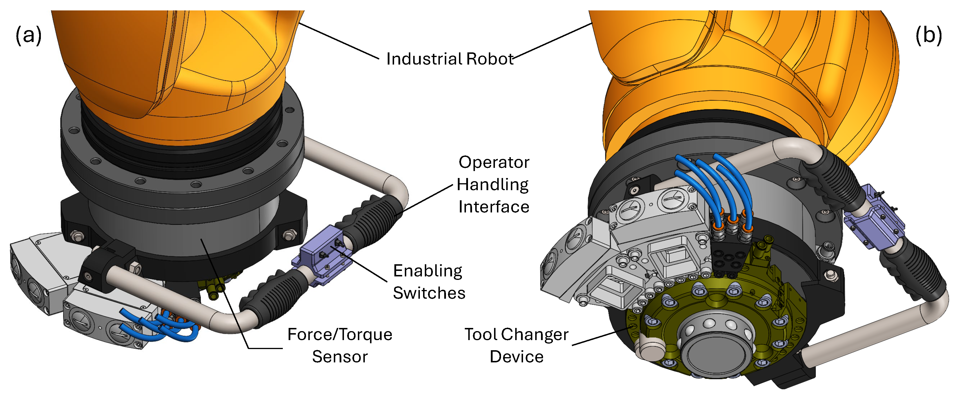
To facilitate the operator task, a dedicated handling tool has been designed and installed on the robot’s end-effector, fixed directly to the sensing flange of the F/T sensor. The tool, whose embodiment design is shown in Figure 3, includes two switches: one to enable manual guidance, thereby disabling the default mode in which both the robot and the linear track operate autonomously based on the loaded production code, and a second switch to toggle between linear track guidance (option a) and robot guidance (option b). An additional safety button is placed near the end-effector to ensure immediate shutdown in case of emergency. Proper signal filtering and thresholding are also implemented within the proposed control logic to ensure dynamic stability of the overall system, as detailed in the next section.
Overall, the intuitive design of the handling tool enhances user interaction and safety, enabling effective manual guidance for teaching tasks across the robotic cell. This approach simplifies the teaching of critical positions, enhancing the usability and adaptability of high-payload IRs in diverse applications.

3. Modeling and Procedure

3.1. Sensor-Based Guidance

As illustrated in Figure 2, the implemented logic utilizes an F/T sensor to detect user inputs and determine the corresponding spatial movement of the robotic system. The sampled external force data ( F x , F y , F z , M x , M y , M z ), which also comprises unnecessary contributions, is processed using the following formulas to derive the effective guiding (i.e., user-applied) forces and torques ( F g , X , F g , Y , F g , Z , M g , X , M g , Y , M g , Z ), expressed in the robot base frame O X Y Z :
F g , X F g , Y F g , Z = R s b F x F x 0 F y F y 0 F z F z 0 0 0 w t o o l
M g , X M g , Y M g , Z = R s b M x M x 0 M y M y 0 M z M z 0 0 z C o G y C o G z C o G 0 x C o G y C o G x C o G 0 R s b T 0 0 w t o o l
with
R s b = c A c B c A s B s C s A c C c A s B c C + s A s C s A c B s A s B s C + c A c C s A s B c C c A s C s B c B s C c B c C
representing the rotation matrix describing the orientation of the F/T sensor frame ( o x y z ) with respect to the robot base frame ( O X Y Z ), computed with angles A, B and C following the Euler ZYX convention. Naturally, the entire vector of values is only to be considered when activating the robot guiding (6 controlled DoF, i.e., option b in Figure 2) while only F g , Y is calculated at PLC level during linear track guiding (option a). In the previous formulas, F x , 0 , F y , 0 , F z , 0 , M x , 0 , M y , 0 , M z , 0 indicate the residual values read from the sensor in no-load conditions, x C o G , y C o G , z C o G are the coordinates of the tool center of gravity with respect to the F/T sensor frame and w t o o l is the tool weight. In Equation (3), the symbols c and s respectively indicate cos and sin. The values resulting from Equations (1) and (2), updated cyclically within the control unit (see Figure 4, related to the option b with 6 DoF), are then further elaborated to ensure proper stability and avoid unstable dynamic conditions. In particular a low-pass filter with a cut-off frequency of 5 Hz is applied to reduce their spectral content and prevent them from inducing a dangerous vibratory state in the robotic system. Indeed, as documented in previous studies (see, e.g., Refs. [40,41]), this class of IRs typically present natural frequencies that range between 7 Hz and 25 Hz. Apart from the inertial and stiffness properties of the robot mechanics (links, joints, gravity balancer, etc.), such frequencies depend on the assumed kinematic configuration, which means they vary during operation. Therefore, the cut-off frequency of the applied filter must be selected carefully.
The filtered signals are then passed through a saturation module, which outputs only values within specified ranges (2 N F g 80 N and 0.25 Nm M g 5 Nm). This ensures that forces and torques outside such intervals have no effect. At this point, the consequent pose corrections (i.e., increments) are calculated as:
Δ X Δ Y Δ Z = K T F g , X F g , Y F g , Z
and
Δ C Δ B Δ A = K R M g , X M g , Y M g , Z
where K T (Translation) and K R (Rotation) are proportional gains, to be experimentally tuned also based on the imposed cycle time [42]. The resulting position and orientation increments ( Δ values in Equations (4) and (5)) represent the output of the manual guiding logic module and are directly fed into the subsequent control module, aimed at executing the requested action at joint level. This could either be the inverse kinematics module in the robot controller (option b) or the servomotor drive units employed in the linear track system (option a). It should be noted that, in the latter case, the implemented control logic will only compute Δ Y to correct the position of the linear track.
Overall, by implementing a controller aimed at dynamically correcting the Cartesian position and orientation of the end-effector at each cycle, the user-applied guiding forces ( F g ) and torques ( M g ) directly modulate the translational ( v g ) and rotational ( ω g ) velocities of the end-effector. This occurs as the computed increments are processed at a fixed time rate, corresponding to the controller cycle time.

3.2. Practical Implementation

As evidenced by the reported mathematical model and with reference to the schematic reported in Figure 4, establishing the forces exerted solely through the operator’s manual action requires the comprehensive understanding of the sensor offset values ( F x - y - z , 0 and M x - y - z , 0 ) as well as the center of gravity ( x C o G , y C o G , z C o G ) and weight ( w t o o l ) of the tool being moved. In practice, these parameters are to be preliminary assessed via a dedicated load sensing procedure (as discussed in Ref. [43]) and saved into global variables to be either recalled within the robot controller (option b) or transferred via dedicated signals to the PLC managing the linear track (option a). With reference to Equation (1), for the manual guidance of the linear track the required information is limited to F x - y - z , 0 as the only computed contribution will be F g , Y . However, also the end-effector orientation (expressed in KUKA via the A, B, C angles) must be communicated to the PLC so that to properly compute the current rotation matrix R s b (see Equation (1) and Figure 2).
The 6-DoF correction logic, illustrated in Figure 4, has been implemented into the KRC4 controller following the approach described in Section 3.1 and leveraging the KUKA RSI package. This enables advanced real-time motion planning by integrating real-time external data into the control loop. The logic is defined within the RSI programming shell using the following commands [39]:
  • DIGIN: reads values (sensor data) from I/O modules;
  • SEN_PREA: reads values stored in the KUKA programming environment (e.g., global variables);
  • TRAFO_ROBFRAME: retrieves current transformation matrix between two frames ( R s b );
  • PT1: applies a low-pass filter;
  • POSCORR: performs Cartesian pose correction with respect to either the robot base frame (as described in Equations (1)–(5)) or the tool (sensor) frame.
The PT1 filter contributes to stabilizing the system and improving the smoothness of the manual guidance, enhancing operator safety. In this regard, the POSCORR block allows the specification of minimum and maximum correction values for each cycle, thereby limiting the velocity and preventing potential damage while serving as an additional safety function. In this work, these limits were set to ± 0.3 mm and ± 0 . 1 . Moreover, the operator can, in any case, activate the safety button placed near the end-effector to ensure immediate shutdown in case of emergency, as discussed in Section 2. The RSI project is configured to run with the IPO_FAST setting, namely with a cycle time of 4 ms. The position and orientation corrections, expressed in the robot base frame, are configured in relative mode, which indicate that the specified values are incrementally added to the previous pose.
A different programming approach is employed for the linear track guidance, where a specific function block has been developed in structured text and uploaded on the Beckhoff PLC. The previous discussed pose correction logic (see Figure 4) has been adapted to the single DoF (Y-axis) by utilizing only Equations (1) and (4) to derive the Cartesian translation. By considering the adopted mechanical transmission, which consists of a rotary reducer and a rack-and-pinion conversion mechanism, the computed correction ( Δ Y ) is converted into a rotational input for the rotary servomotors as follows:
Δ θ = i Δ Y r p i n i o n
where i = 25 is the reducer reduction ratio, whereas r p i n i o n = 53.05 mm is the radius of the pinion engaging the rack (see Table 1). The angular position increment Δ θ is cyclically transmitted (every 1 ms) via EtherCAT to the drive units, where the position control loops are closed. In line with the previously discussed RSI scheme, the PLC-based control framework implements proper signal filtering and saturation on the computed Δ θ to avoid instability in the mechatronic system and to ensure operator safety.
The proposed software frameworks are shared in the Github repository (https://github.com/XiLab-Robotics/Hand-Guiding-IR-ExtendedWorkspaces.git, accessed on 18 October 2025) to easy reproduction and future development.

3.3. Load Sensing

As revealed by Equations (1) and (2) and further discussed in Section 3.2, both the implemented logic schemes (mode a on PLC, mode b on RSI) require the values of F x - y - z , 0 . Furthermore, the RSI-based version also requires M x - y - z , 0 , x C o G , y C o G , z C o G and w t o o l to properly compute the 6-DoF correction. To effectively assess these quantities, while considering the dynamic nature of signal offsets and the need to accommodate various tools at the end-effector, an automatic load sensing procedure has been implemented. The procedure involves positioning the robot in different poses by re-orienting the attached tool (and thus the F/T sensor) and computing the value for each force and torque component across the different directions. Specifically, once the robot is stabilized in each of the commanded poses, the RSI is activated for 5 s recalling a purposely defined RSI measurement project that samples real-time data through the F/T sensor and writes the averaged values on pre-determined local variables (MAP2SEN_PREA command). Afterwards, the script proceeds with the estimation of the unknown parameters, which are subsequently stored into global variables that will regularly assessed from the controller during the effective manual guidance operation.
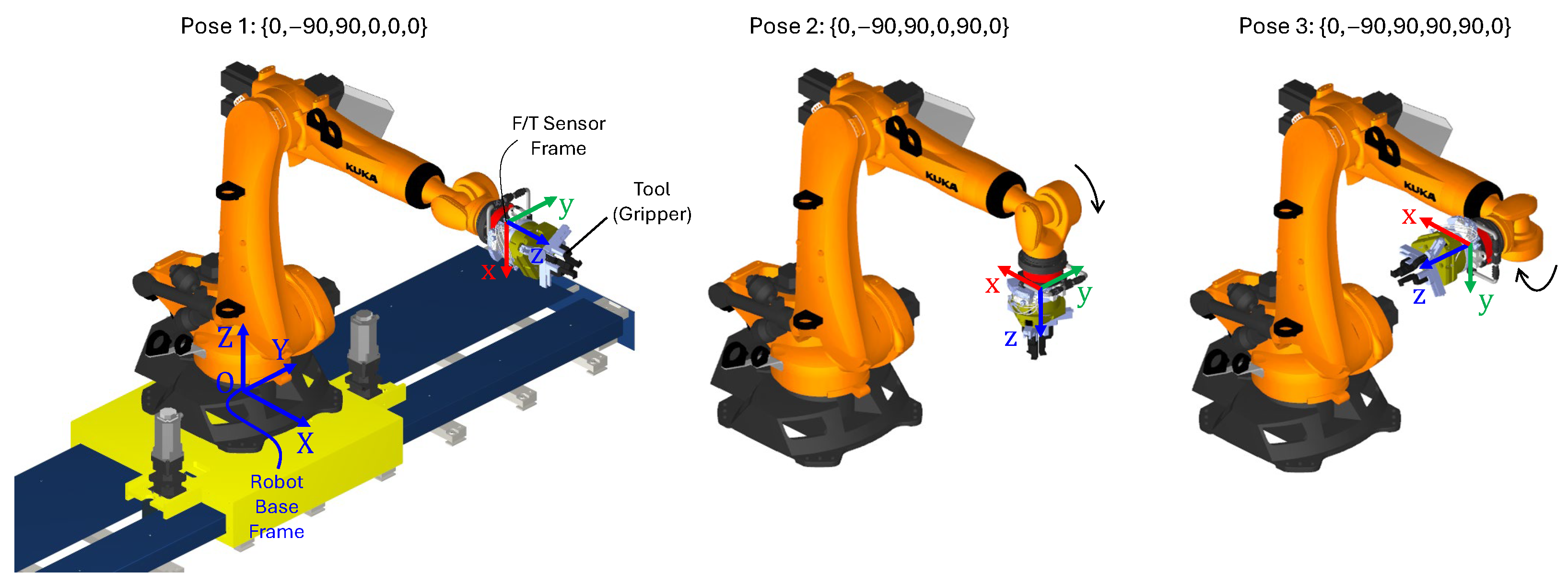
As illustrated in Figure 5, three poses were strategically selected by fixing the first three joints at (0, −90, 90) and orienting the tool with the last three joints set to (0, 0, 0), (0, 90, 0) and (90, 90, 0). These poses respectively align the positive x-, z-, and y-axis of the F/T sensor with the direction of gravity. The following parameters are recorded during the experiment:
  • Pose 1 F z 0 , F x , P 1 , M x 0 , M y , P 1 , M z , P 1
  • Pose 2 F y 0 , F z , P 2 , M x , P 2 , M y , P 2 , M z 0
  • Pose 3 F x 0 , F y , P 3 , M x , P 3 , M y 0 , M z , P 3
Here the subscript P 1 - 2 - 3 associates the measurements with the corresponding robot pose. Using these inputs, which are temporarily stored in local variables of the robot program, the tool weight is estimated for each commanded pose by considering the force component measured along the gravity direction (e.g., F x , P 1 ) and subtracting the corresponding initial sensor offset ( F x 0 ). The results obtained from the three tests are then averaged as follows:
w t o o l = F x , P 1 F x 0 + F y , P 3 F y 0 + F z , P 2 F z 0 3
The coordinates of the center of gravity are then calculated as:
x C o G = M y , P 2 M y 0 + M z , P 3 M z 0 2 w t o o l
y C o G = M z , P 1 M z 0 + M x , P 2 M x 0 2 w t o o l
z C o G = M y , P 1 M y 0 + M x , P 3 M x 0 2 w t o o l
As evident in Equations (7)–(10), the redundancy in the recorded data is leveraged to obtain averaged values, enhancing the robustness of the results. Naturally, the procedure is to be repeated for each of the utilized tools, including the situation where only the handling tool is attached to the end-effector (as depicted in Figure 1). The obtained results are then stored into global variables which can be recalled from any robot script or directly transferred to the PLC. Figure 6 presents an example of load sensing assessment, conducted without any gripping tools attached to the end-effector. The plot illustrates the force signals recorded for three poses, specifically highlighting the net levels obtained by subtracting the initial offset F x 0 , F y 0 and F z 0 . As it can be seen, the calculated w t o o l is 142 N, representing the concurrent contribution of the installed handling device (Figure 3) and the tool changer device.

4. Experimental Testing

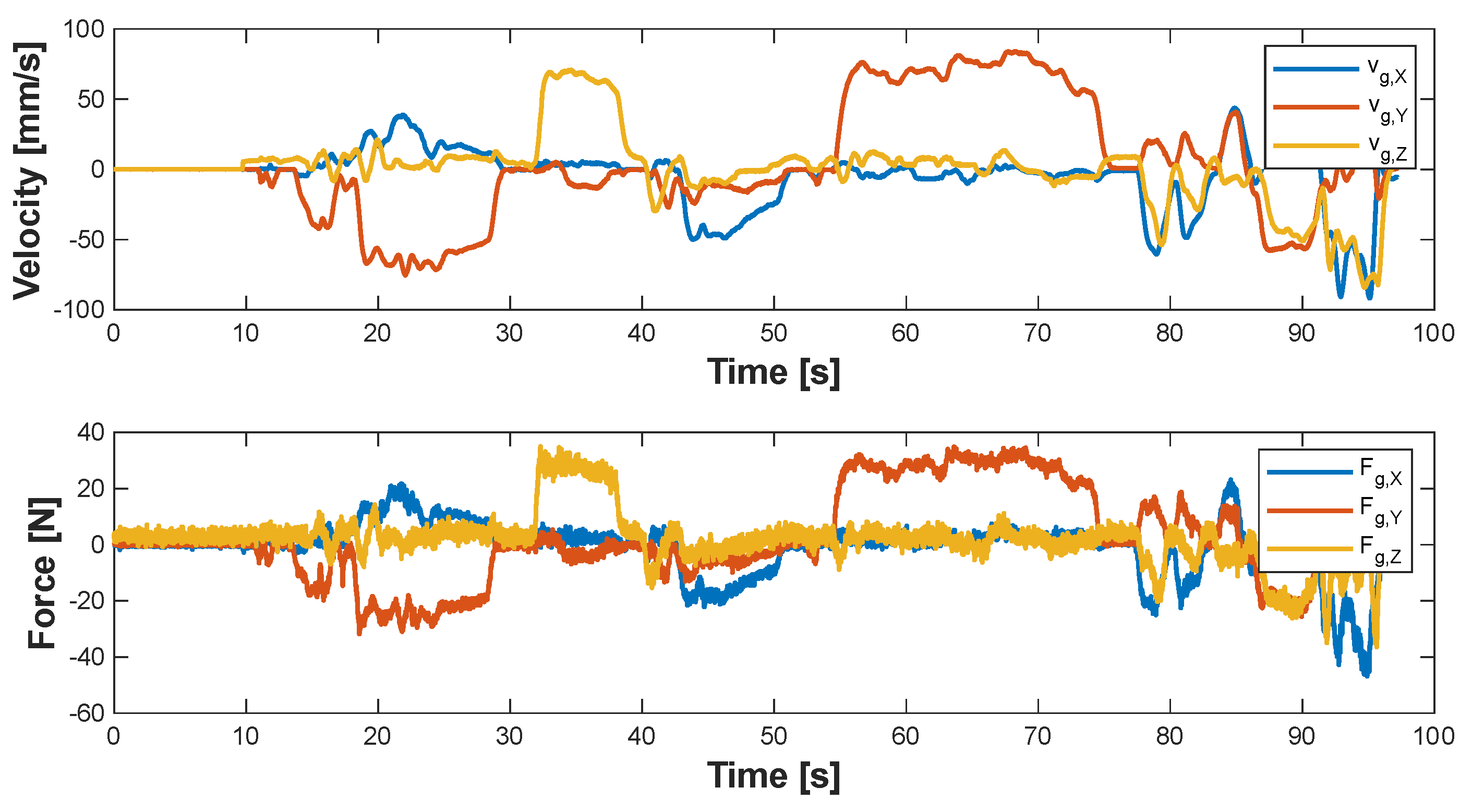
The proposed framework has been experimentally validated through a series of manually guided movements on the physical cell. As illustrated in Figure 7, the pose teaching starts at the home pose, sequentially enabling the linear track guidance and the robot guidance to rapidly approach the tool storage area. During this process, the operator successfully taught three targets for the precise picking and releasing of the three gripper tools, which were recorded for use in future robot programs. This was achieved by manually activating a digital input in the RSI project and utilizing the POSACT command to store the current pose, expressed in the robot base frame, into new variables. These recorded points define the sequence of positions the robot follows during its production cycle to correctly pick or release the tools in the storage. During the test, the forces and end-effector velocities were saved using the KUKA tracing function. Figure 8 presents a portion of the experiment that highlights the computed guiding forces and the corresponding translational velocities during the robot guidance.
To quantitatively assess the advantages of the proposed manual guidance approach, the experiment described above was carried out involving two users with different experience levels, namely an expert and a non-expert operator. The users were asked to teach the three targets within the tool storage area using both the conventional teach pendant interface and then the proposed hand-guiding control mode. Each test was repeated five times per user and per method, and the average completion times were computed. The results, summarized in Table 2, clearly show that both users benefit from the manual guidance approach, which significantly reduces the time required to complete the teaching task. In particular, the expert user achieved a time reduction of approximately 56%, while the non-expert user experienced an even greater improvement of 63%.
Overall, these results confirm that the proposed framework not only ensures stable and intuitive control but also substantially enhances human–robot interaction efficiency, reducing setup times for industrial tasks such as target teaching and path definition.

5. Conclusions

The paper reports an engineering method for enabling manual guidance on high-payload IRs, with a specific focus on setups implementing external additional axes to extend the cell workspace. The approach leverages an F/T sensor mounted on the robot end-effector to perform online corrections of the robot pose, supporting two operational modes with either the linear track or the robot moving. A common control logic is developed and integrated into the commercial controllers, namely a KUKA KRC4 controlling the 6 axes of the manipulator and a Beckhoff PLC dedicated to the additional linear axis. The logic is further elaborated to operate safely and update the robot pose without inducing unstable dynamic conditions. All the implementation steps are described in detail to automate the procedure and facilitate its reproduction on a variety of commercial controllers, including a load sensing procedure aimed at assessing the mass properties of the attached tool, thus allowing the accurate computation of the operator’s guiding force. The proposed approach has been validated on the physical cell by replicating a standard target teaching scenario, namely a common task performed by the operator during initial cell calibration or production resets. The performance of two users with different levels of expertise was evaluated, revealing that the use of the manual guidance method reduced the task completion time by more than 55% for both users compared with the conventional teach pendant, thus confirming the effectiveness and practical advantages of the developed framework.
Future developments will focus on integrating impedance-learning strategies into the proposed architecture to further enhance compliance and safety during contact-intensive manual guidance tasks, thereby extending its applicability to a broader range of industrial scenarios.

Author Contributions

Conceptualization, P.B. and P.A.L.G.; Methodology, P.A.L.G., M.S. and A.T.; Formal analysis, P.A.L.G. and M.S.; Writing—original draft preparation, P.B. and A.T.; Writing—review and editing, P.B. and M.P.; Coordination, M.P. All authors have read and agreed to the published version of the manuscript.

Funding

This research was funded by the European Community’s HORIZON 2020 Programme under grant agreement No. 958303 (PeneloPe).

Data Availability Statement

The original data presented in the study is openly available at this link https://github.com/XiLab-Robotics/Hand-Guiding-IR-ExtendedWorkspaces.git (accessed on 18 October 2025).

Conflicts of Interest

The authors declare no conflict of interest.

References

  1. Zhong, R.Y.; Xu, X.; Klotz, E.; Newman, S.T. Intelligent manufacturing in the context of industry 4.0: A review. Engineering 2017, 3, 616–630. [Google Scholar] [CrossRef]
  2. Oztemel, E.; Gursev, S. Literature review of Industry 4.0 and related technologies. J. Intell. Manuf. 2020, 31, 127–182. [Google Scholar] [CrossRef]
  3. International Federation of Robotics World Robotics 2025: Industrial Robots. 2025. Available online: https://ifr.org/ifr-press-releases/news/global-robot-demand-in-factories-doubles-over-10-years (accessed on 29 October 2025).
  4. Bilancia, P.; Schmidt, J.; Raffaeli, R.; Peruzzini, M.; Pellicciari, M. An overview of industrial robots control and programming approaches. Appl. Sci. 2023, 13, 2582. [Google Scholar] [CrossRef]
  5. Merdan, M.; Hoebert, T.; List, E.; Lepuschitz, W. Knowledge-based cyber-physical systems for assembly automation. Prod. Manuf. Res. 2019, 7, 223–254. [Google Scholar] [CrossRef]
  6. Zheng, Y.; Liu, W.; Zhang, Y.; Han, L.; Li, J.; Lu, Y. Integration and calibration of an in situ robotic manufacturing system for high-precision machining of large-span spacecraft brackets with associated datum. Robot.—Comput.—Integr. Manuf. 2025, 94, 102928. [Google Scholar] [CrossRef]
  7. Halim, J.; Eichler, P.; Krusche, S.; Bdiwi, M.; Ihlenfeldt, S. No-code robotic programming for agile production: A new markerless-approach for multimodal natural interaction in a human-robot collaboration context. Front. Robot. AI 2022, 9, 1001955. [Google Scholar] [CrossRef]
  8. Safeea, M.; Neto, P. Precise positioning of collaborative robotic manipulators using hand-guiding. Int. J. Adv. Manuf. Technol. 2022, 120, 5497–5508. [Google Scholar] [CrossRef]
  9. Dhanda, M.; Rogers, B.A.; Hall, S.; Dekoninck, E.; Dhokia, V. Reviewing human-robot collaboration in manufacturing: Opportunities and challenges in the context of industry 5.0. Robot.—Comput.—Integr. Manuf. 2025, 93, 102937. [Google Scholar] [CrossRef]
  10. Vicentini, F. Collaborative robotics: A survey. J. Mech. Des. 2021, 143, 040802. [Google Scholar] [CrossRef]
  11. Bejarano, R.; Ferrer, B.R.; Mohammed, W.M.; Lastra, J.L.M. Implementing a human-robot collaborative assembly workstation. In Proceedings of the 2019 IEEE 17th International Conference on Industrial Informatics (INDIN), Helsinki, Finland, 22–25 July 2019; IEEE: Piscataway, NJ, USA, 2019; Volume 1, pp. 557–564. [Google Scholar]
  12. Malik, A.A.; Brem, A. Digital twins for collaborative robots: A case study in human-robot interaction. Robot.—Comput.—Integr. Manuf. 2021, 68, 102092. [Google Scholar] [CrossRef]
  13. Buerkle, A.; Eaton, W.; Al-Yacoub, A.; Zimmer, M.; Kinnell, P.; Henshaw, M.; Coombes, M.; Chen, W.H.; Lohse, N. Towards industrial robots as a service (IRaaS): Flexibility, usability, safety and business models. Robot.—Comput.—Integr. Manuf. 2023, 81, 102484. [Google Scholar] [CrossRef]
  14. Pan, Z.; Polden, J.; Larkin, N.; Van Duin, S.; Norrish, J. Recent progress on programming methods for industrial robots. Robot.—Comput.—Integr. Manuf. 2012, 28, 87–94. [Google Scholar] [CrossRef]
  15. Rodriguez-Guerra, D.; Sorrosal, G.; Cabanes, I.; Calleja, C. Human-robot interaction review: Challenges and solutions for modern industrial environments. IEEE Access 2021, 9, 108557–108578. [Google Scholar] [CrossRef]
  16. Kolbeinsson, A.; Lagerstedt, E.; Lindblom, J. Foundation for a classification of collaboration levels for human-robot cooperation in manufacturing. Prod. Manuf. Res. 2019, 7, 448–471. [Google Scholar] [CrossRef]
  17. Fujii, M.; Murakami, H.; Sonehara, M. Study on application of a human-robot collaborative system using hand-guiding in a production line. IHI Eng. Rev. 2016, 49, 24–29. [Google Scholar]
  18. Kim, M.; Zhang, Y.; Jin, S. Control strategy for direct teaching of non-mechanical remote center motion of surgical assistant robot with force/torque sensor. Appl. Sci. 2021, 11, 4279. [Google Scholar] [CrossRef]
  19. Lee, S.Y.; Lee, Y.S.; Park, B.S.; Lee, S.H.; Han, C.S. MFR (Multipurpose Field Robot) for installing construction materials. Auton. Robot. 2007, 22, 265–280. [Google Scholar] [CrossRef]
  20. Schraft, R.D.; Meyer, C.; Parlitz, C.; Helms, E. Powermate-a safe and intuitive robot assistant for handling and assembly tasks. In Proceedings of the 2005 IEEE International Conference on Robotics and Automation, Barcelona, Spain, 18–22 April 2005; IEEE: Piscataway, NJ, USA, 2005; pp. 4074–4079. [Google Scholar]
  21. Stepputat, M.; Neumann, S.; Wippermann, J.; Heyser, P.; Meschut, G.; Beuss, F.; Sender, J.; Fluegge, W. Flexible Automation through Robot-Assisted Mechanical Joining in Small Batches. Procedia CIRP 2023, 120, 457–462. [Google Scholar] [CrossRef]
  22. Massa, D.; Callegari, M.; Cristalli, C. Manual guidance for industrial robot programming. Ind. Robot. Int. J. 2015, 42, 457–465. [Google Scholar] [CrossRef]
  23. Reyes-Uquillas, D.; Hsiao, T. Safe and intuitive manual guidance of a robot manipulator using adaptive admittance control towards robot agility. Robot.—Comput.—Integr. Manuf. 2021, 70, 102127. [Google Scholar] [CrossRef]
  24. Haninger, K.; Radke, M.; Vick, A.; Krüger, J. Towards high-payload admittance control for manual guidance with environmental contact. IEEE Robot. Autom. Lett. 2022, 7, 4275–4282. [Google Scholar] [CrossRef]
  25. Comau S.p.A. AURA—Collaborative Robotics for High Payload Applications. 2024. Available online: https://www.comau.com/en/aura-collaborative-robotics-for-high-payload-applications/ (accessed on 18 October 2025).
  26. FANUC. Hand Guidance Accessory for Standard Robots. 2024. Available online: https://www.fanuc.eu/eu-en/accessory/accessory/hand-guidance (accessed on 18 October 2025).
  27. Farajtabar, M.; Charbonneau, M. The path towards contact-based physical human—Robot interaction. Robot. Auton. Syst. 2024, 182, 104829. [Google Scholar] [CrossRef]
  28. Robla-Gómez, S.; Becerra, V.M.; Llata, J.R.; Gonzalez-Sarabia, E.; Torre-Ferrero, C.; Perez-Oria, J. Working together: A review on safe human-robot collaboration in industrial environments. IEEE Access 2017, 5, 26754–26773. [Google Scholar] [CrossRef]
  29. ISO 10218-1:2011; Robots and Robotic Devices—Safety Requirements for Industrial Robots. ISO: Geneva, Switzerland, 2011. Available online: https://www.iso.org/standard/51330.html (accessed on 15 January 2025).
  30. ISO/TS 15066:2016; Robots and Robotic Devices—Collaborative Robots. ISO: Geneva, Switzerland, 2016. Available online: https://www.iso.org/standard/62996.html (accessed on 15 January 2025).
  31. Liu, G.; Li, Q.; Fang, L.; Han, B.; Zhang, H. A new joint friction model for parameter identification and sensor-less hand guiding in industrial robots. Ind. Robot. Int. J. Robot. Res. Appl. 2020, 47, 847–857. [Google Scholar] [CrossRef]
  32. Yao, B.; Zhou, Z.; Wang, L.; Xu, W.; Liu, Q. Sensor-less external force detection for industrial manipulators to facilitate physical human-robot interaction. J. Mech. Sci. Technol. 2018, 32, 4909–4923. [Google Scholar] [CrossRef]
  33. Yao, B.; Zhou, Z.; Wang, L.; Xu, W.; Liu, Q.; Liu, A. Sensorless and adaptive admittance control of industrial robot in physical human- robot interaction. Robot.—Comput.—Integr. Manuf. 2018, 51, 158–168. [Google Scholar] [CrossRef]
  34. de Gea Fernández, J.; Mronga, D.; Günther, M.; Knobloch, T.; Wirkus, M.; Schröer, M.; Trampler, M.; Stiene, S.; Kirchner, E.; Bargsten, V.; et al. Multimodal sensor-based whole-body control for human–robot collaboration in industrial settings. Robot. Auton. Syst. 2017, 94, 102–119. [Google Scholar] [CrossRef]
  35. Cherubini, A.; Navarro-Alarcon, D. Sensor-based control for collaborative robots: Fundamentals, challenges, and opportunities. Front. Neurorobotics 2021, 14, 576846. [Google Scholar] [CrossRef] [PubMed]
  36. Bascetta, L.; Ferretti, G.; Magnani, G.; Rocco, P. Walk-through programming for robotic manipulators based on admittance control. Robotica 2013, 31, 1143–1153. [Google Scholar] [CrossRef]
  37. Xing, X.; Burdet, E.; Si, W.; Yang, C.; Li, Y. Impedance learning for human-guided robots in contact with unknown environments. IEEE Trans. Robot. 2023, 39, 3705–3721. [Google Scholar] [CrossRef]
  38. Ljasenko, S.; Lohse, N.; Justham, L. Dynamic vs dedicated automation systems-a study in large structure assembly. Prod. Manuf. Res. 2020, 8, 35–58. [Google Scholar] [CrossRef]
  39. KUKA Robot Sensor Interface. Available online: https://www.kuka.com/en-us/products/robotics-systems/software/application-software/kuka_robotsensorinterface (accessed on 15 January 2025).
  40. Ferrarini, S.; Bilancia, P.; Raffaeli, R.; Peruzzini, M.; Pellicciari, M. A method for the assessment and compensation of positioning errors in industrial robots. Robot.—Comput.—Integr. Manuf. 2024, 85, 102622. [Google Scholar] [CrossRef]
  41. Cvitanic, T.; Melkote, S.N. A new method for closed-loop stability prediction in industrial robots. Robot.—Comput.—Integr. Manuf. 2022, 73, 102218. [Google Scholar] [CrossRef]
  42. Tutarini, A.; Bilancia, P.; León, J.F.R.; Viappiani, D.; Pellicciari, M. Design and implementation of an active load test rig for high-precision evaluation of servomechanisms in industrial applications. J. Ind. Inf. Integr. 2024, 42, 100696. [Google Scholar] [CrossRef]
  43. Hu, J.; Li, C.; Chen, Z.; Yao, B. Precision motion control of a 6-DoFs industrial robot with accurate payload estimation. IEEE/ASME Trans. Mechatronics 2020, 25, 1821–1829. [Google Scholar] [CrossRef]
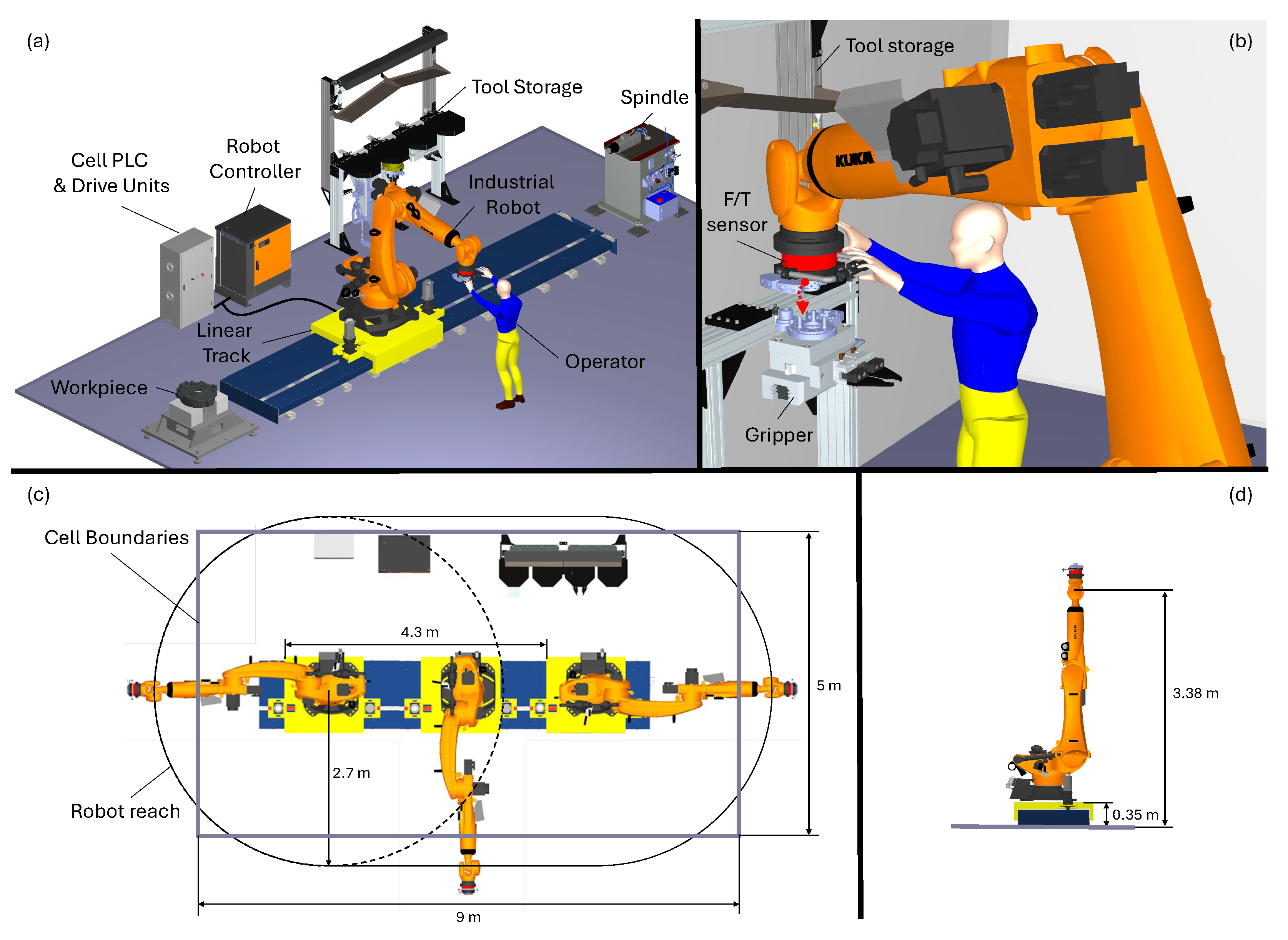
Figure 1. Manual guidance in robotic cells with extended workspaces: (a) cell overview; (b) example of pose teaching; (c) cell layout; (d) maximum vertical reach.
Machines 13 01016 g001
Figure 2. Functional schematic of the proposed manual guiding framework and operation modes: (a) Linear track guidance (1-DoF) and (b) Robot guidance (6-DoF).
Machines 13 01016 g002
Figure 3. Embodiment design of the handling tool mounted at the robot end-effector: (a) overview of the manual interface with details of the switches; (b) bottom oriented view illustrating the tool changer device.
Machines 13 01016 g003
Figure 4. Schematic of the RSI 6-DoF correction logic within the KUKA KRC4 controller. The colors identify the different signal processing steps.
Machines 13 01016 g004
Figure 5. Robot poses commanded during the load sensing procedure.
Machines 13 01016 g005
Figure 6. Evaluation of tool weight during the load sensing for each robot pose.
Machines 13 01016 g006
Figure 7. Physical test on the robotic cell.
Machines 13 01016 g007
Figure 8. Extracted guiding forces and imposed velocities of the end-effector during the tool storage approach phase.
Machines 13 01016 g008
Table 1. Characteristics of the commercial components installed in the robotic cell.
DeviceModelCharacteristics
RobotKUKA
KR210 R2700 Prime
Reach: 2.7 m
Payload: 210 kg
Mass (including box and cables): 1190 kg
Controller: KRC4 (KSS version 8.3.25)
Linear trackCustom solutionStroke: 4.3 m
Platform Mass: 940 kg
Servomotors: 2 Beckhoff AM8052
Drive units: 2 Beckhoff AX8118
Reducers: 2 Stoeber PH732 (red. ratio 25)
Rack-and-pinion: pinion radius of 53.05 mm
Controller: Beckhoff PLC CX5140
ToolsSchunk
Tool-1: PZN+240/2
Tool-2: PGN+380/2 & PGN+160/1
Mass Tool-1: 80 kg
Mass Tool-2: 60 kg
F/T sensorSchunk
FTN SI-1800-350
F x , F y range: 0–1800 N
F z range: 0–4500 N
M x , M y , M z range: 0–350 Nm
SpindleHSD
ES 939A 4P
Peak power: 13.5 kW
Speed range: 6000–24,000 rpm
Table 2. Comparison of target teaching completion times for expert and non-expert users in a pick-and-place task.
UserTeach Pendant TimeManual Guiding TimeImprovement
Expert operator7 min 20 s3 min 14 s55.9%
Non-expert operator11 min 52 s4 min 23 s63%
Disclaimer/Publisher’s Note: The statements, opinions and data contained in all publications are solely those of the individual author(s) and contributor(s) and not of MDPI and/or the editor(s). MDPI and/or the editor(s) disclaim responsibility for any injury to people or property resulting from any ideas, methods, instructions or products referred to in the content.