1. Introduction
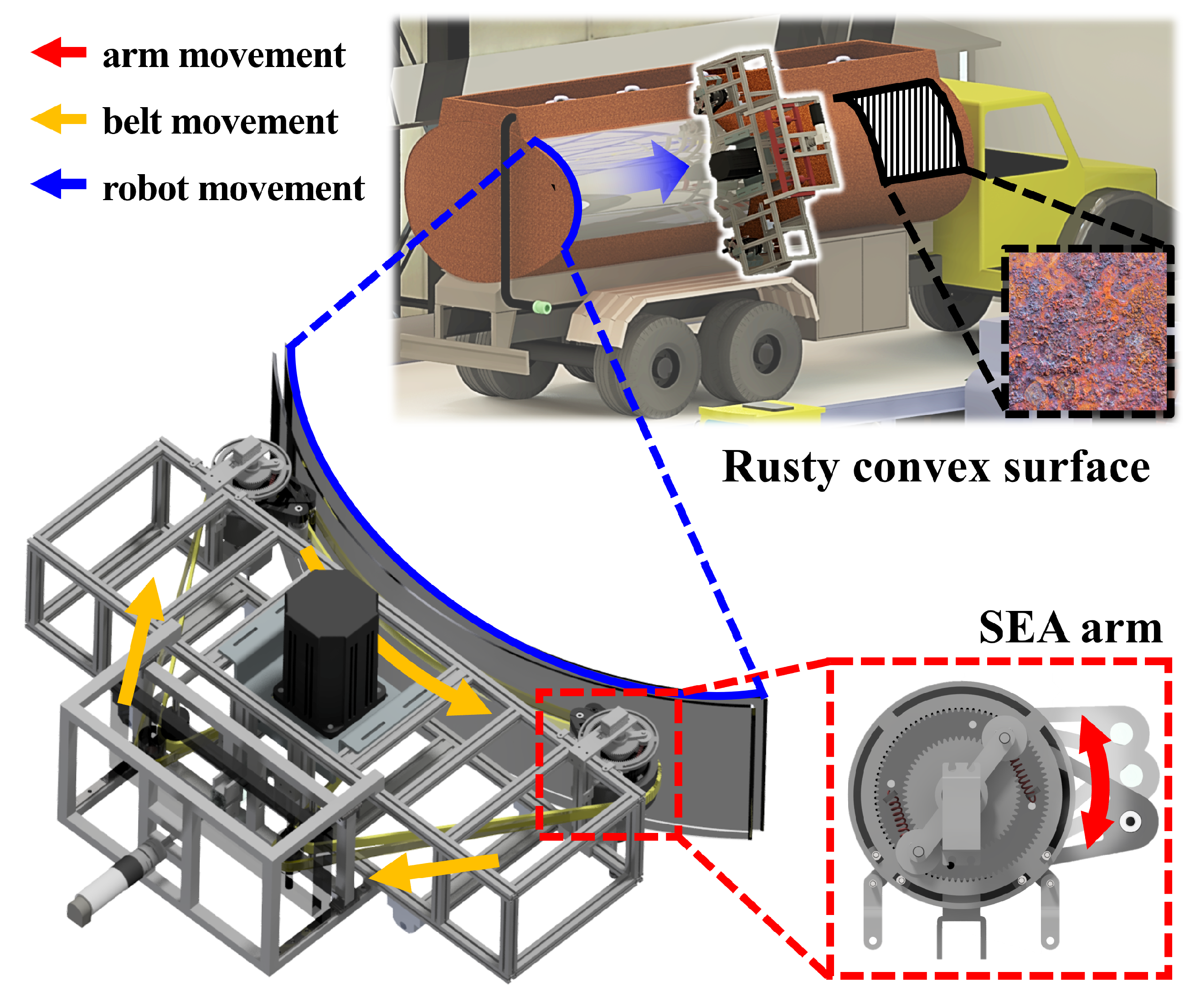
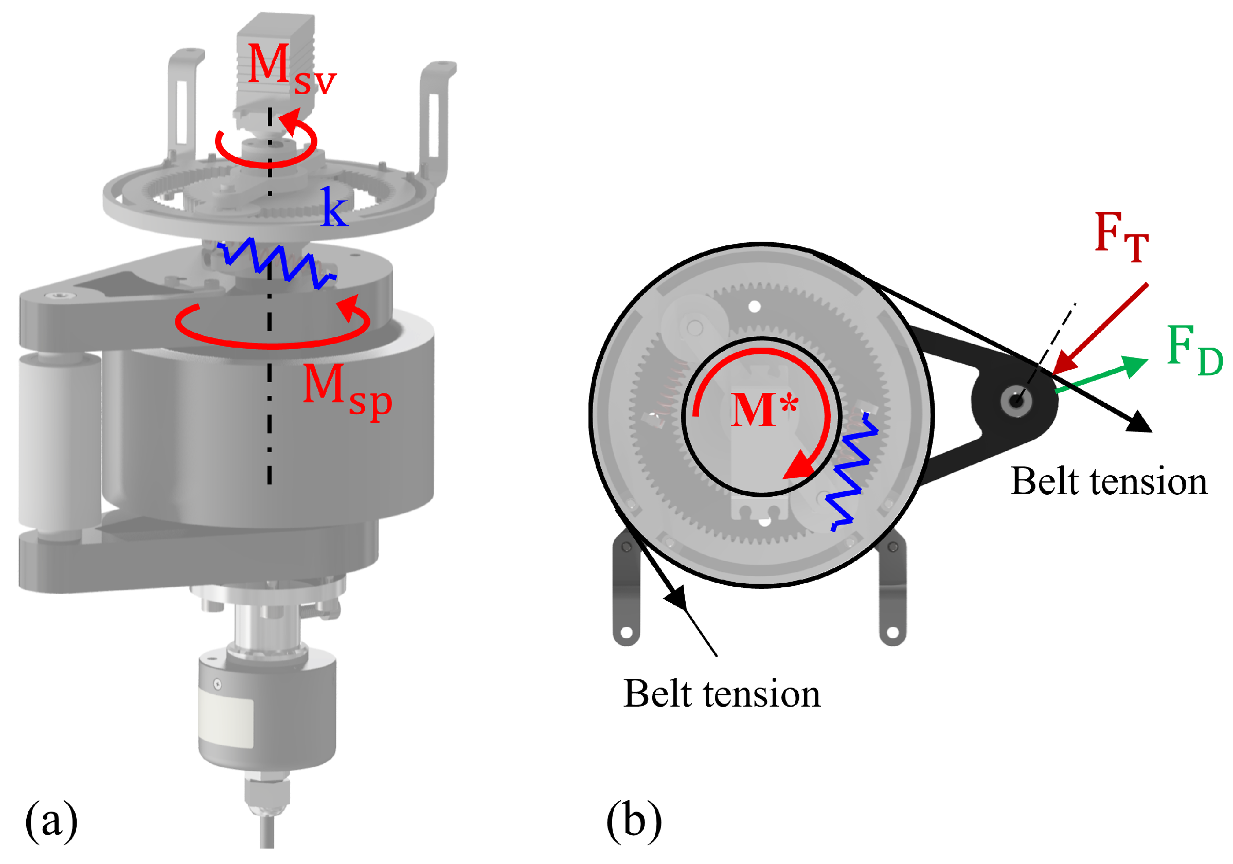
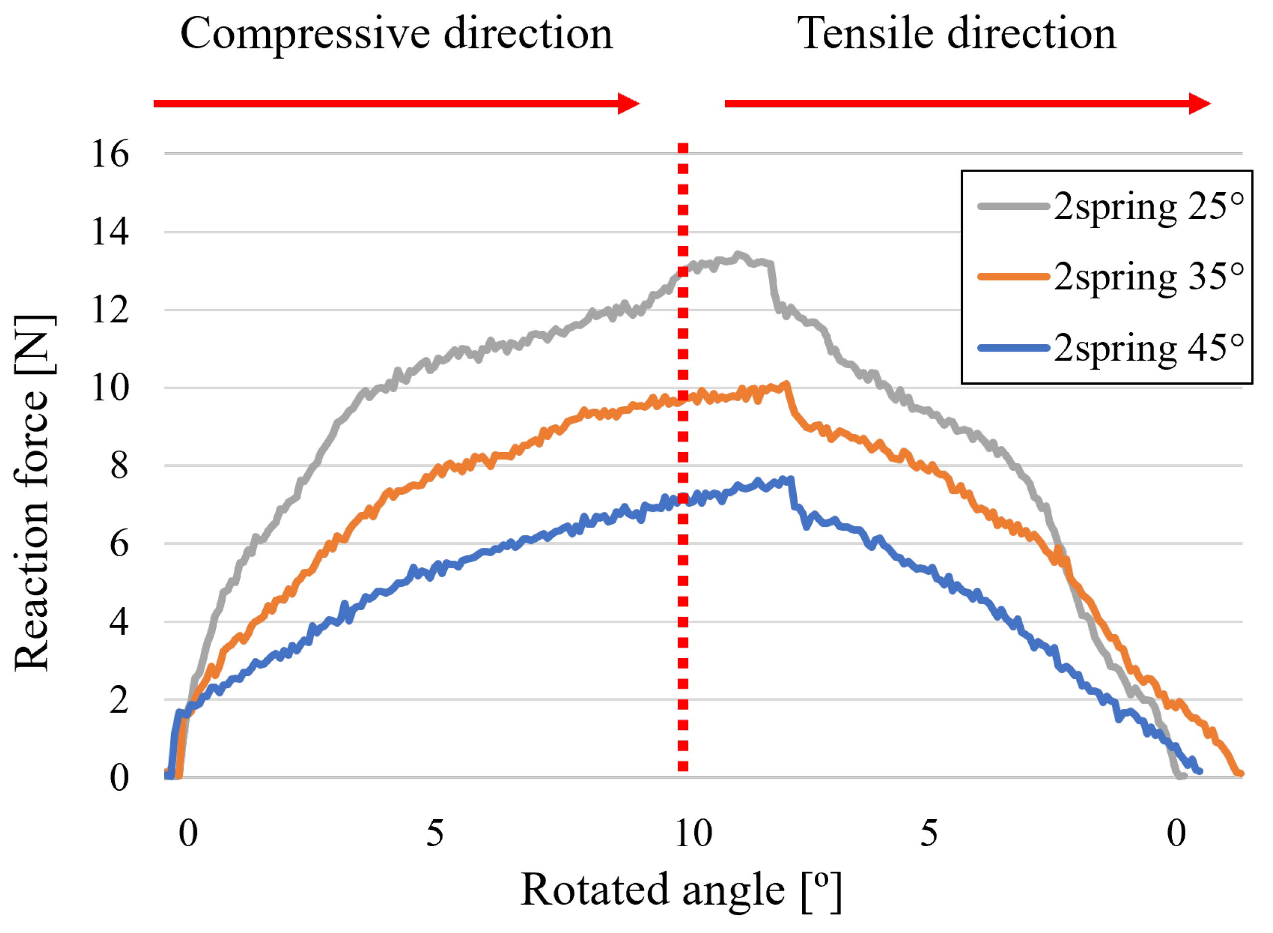
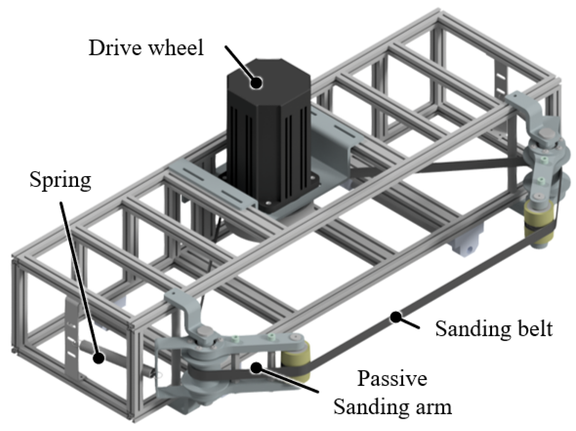
Sanding, which is the process of making something smooth by rubbing it with something rough, is a crucial process in various industries, ranging from manufacturing to maintenance and repair. It serves multiple purposes, such as improving the aesthetic appeal of surfaces, preparing for subsequent painting or coating, and removing unwanted materials such as rust or other contaminants for safety. However, traditional sanding processes rely predominantly on manual labor, which presents several challenges. First, manual sanding exposes workers to continuous vibrations that can have detrimental musculoskeletal health effects over time. Second, maintaining consistency while manually sanding large areas is difficult because of the inherent variability in human performance, which often results in uneven finishes and makes it almost impossible to restore over-sanded surfaces. Finally, manual sanding generates dust that can harm the respiratory health of workers if not properly managed with additional facilities or protective gear. Owing to the challenges associated with manual sanding, there is an increasing need for automation. Automated solutions can not only address the aforementioned issues but also enhance productivity and reduce operational costs. To meet such needs, this study proposes a mechanism adapting a series elastic actuator (SEA) and a re-tensioner as a new way to control the tension and normal force of a sanding robot for large-area convex surfaces, as shown in
Figure 1.
Abrasion robots were grouped by mechanism into belt, orbit, and wheel modules. Prior work spans belt grinding and polishing, orbit polishing heads, and wheel grinding for seams and edges [
1,
2,
3]. Most reported systems target small parts or locally planar and strip-like regions such as turbine blades, weld seams, and furniture panels [
4,
5]. By contrast, large, doubly curved surfaces demand both high structural capacity and precise coordination of position and contact force over a wide interface, which remains difficult in practice [
6,
7,
8]. Recent work on compliant/SEA-equipped grinding end-effectors and force-planning on complex curved parts further underscores the need for active force/tension regulation in large-area finishing [
9,
10,
11]. Performance is often summarized by coverage, roughness, or mark suppression; only a few studies explicitly quantify how normal force is distributed spatially across large contact areas [
12]. This gap matters because non-uniform force across the belt–workpiece interface degrades coverage and produces local over-removal on convex geometries.
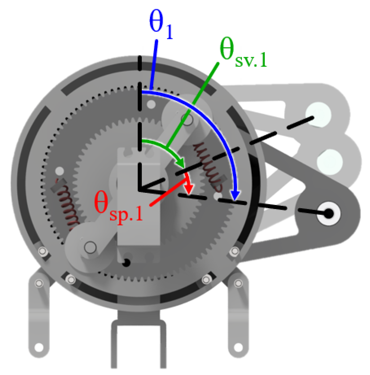
Against this backdrop, our study frames a concrete control problem for large-area convex sanding: regulating belt tension and the spatial distribution of normal force across the full belt width. We adopt series elastic actuators on the sanding arms to estimate reaction force indirectly at the contact without load cells and to provide compliance to contact transients under vibration and dust typical of belt abrasion. In our previous passive-arm experiments, distinct groove marks indicated sudden jumps in normal force at the contact [
13]. Integrating SEAs reduces the mechanical output impedance of the arms and improves tolerance to impact loads, mitigating those jumps. In addition, an active re-tensioner is introduced to maintain appropriate belt tension along the contacting span, addressing belt tracking and tension variability that conventional arrangements do not actively control. These design choices directly target the two limitations above—limited instantaneous coverage and non-uniform spatial force—and set up the measurable objectives evaluated in this paper.
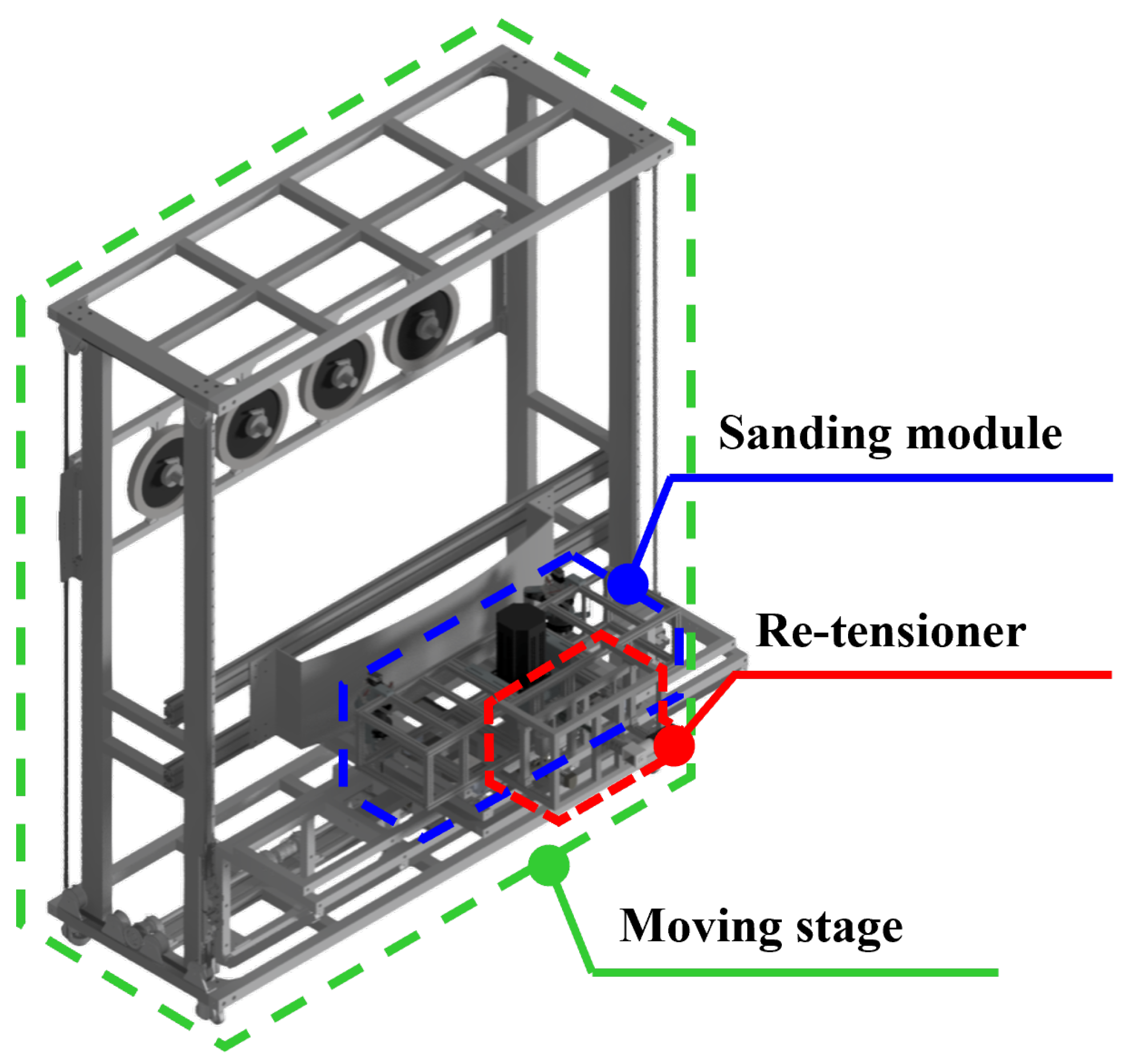
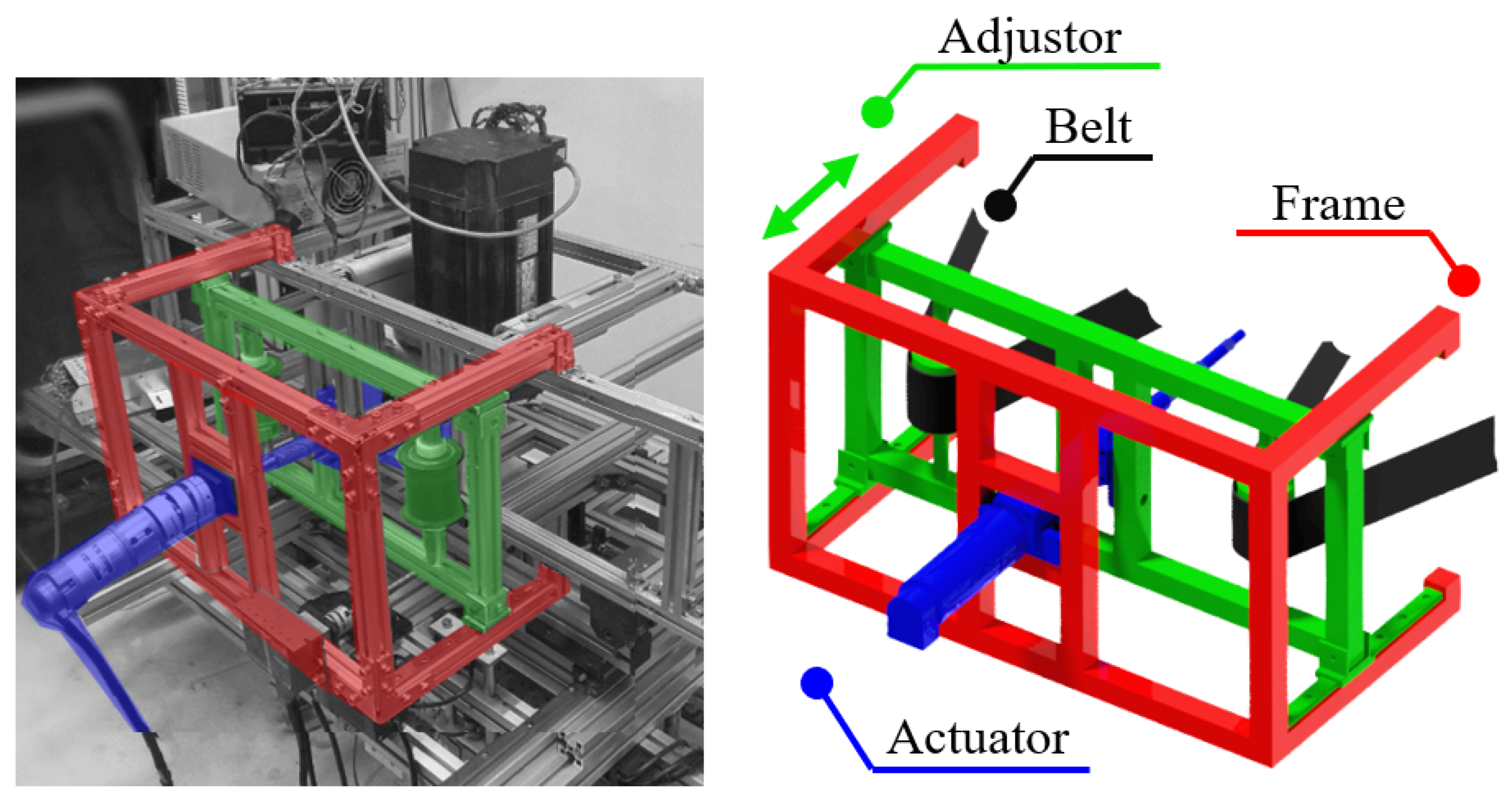
The re-tensioner mitigates the challenges of belt detachment and escapes from its designated track when transitioning to a multi-wheel belt system. Owing to the limitations stemming from their primary purpose, only two wheels that did not contact the target surface were left capable of guiding the belt track. Along with the attached idlers, this configuration allowed the maintenance of optimal belt tension, ensuring that the belt remained securely on track throughout the sanding process. In doing so, we not only mitigated the risks associated with belt detachment but also optimized the overall efficiency of our multi-wheel belt system for improved performance.
Large-area finishing on doubly curved workpieces is limited by two concrete factors. Prior systems typically present a narrow instantaneous contact patch and operate from fixed tool positions, which constrains the achievable coverage across the belt width during a single pass. In addition, the spatial distribution of normal force across the belt–workpiece interface is often non-uniform, leading to locally excessive removal and visible banding rather than consistent surface quality.
This study addresses these gaps with measurable objectives evaluated under controlled operating conditions. The first objective is to achieve full-width contact across the nominal belt span during each vertical pass so that the belt engages the entire width rather than a narrow strip. The second objective is to promote uniform normal-force distribution across the contact region, reducing spatial variation relative to a conventional belt sander.
The evaluation focuses on steel plates with convex curvature representative of the target application. Operating conditions reported in the following sections include a belt width of 50 mm, vertical feed of 50 mm/min, and drive wheel speed of 300 rpm. Stating the objectives in terms of belt width coverage and force uniformity links the mechanism and control choices to practical finishing outcomes on large convex surfaces.
The sanding belt tension is controlled using the proportional–integral (PI) control method to ensure optimal belt tightness throughout the sanding process. This allows consistent and uniform sanding and avoids surface warping. PI control is also used to regulate the reaction force applied to the target surface. This enables adaptive and compliant interactions between the sanding belt and convex target surfaces, accommodating variations in curvature, and preventing uneven surfaces from excessive forces. By adjusting the applied force based on real-time feedback, damage to delicate surfaces can be prevented while maintaining effective and well-distributed material removal.
The remainder of this paper is organized as follows.
Section 2 describes the robot mechanism, including the kinematics and dynamic modeling.
Section 3 describes the robot control.
Section 4 presents the experimental setup and corresponding results. Finally,
Section 5 concludes the paper.
3. Control System
Simple PI control associated with an active SEA system is more desirable than impedance control when the goal is to maintain a constant force over time with limited dynamic interaction [
16]. In classical interaction control, impedance control shapes a desired dynamic relation between motion and force at the contact, which is advantageous for tasks requiring active rendering of inertia, damping, or stiffness and for broadband interaction [
17]. Our application targets constant-force tracking under limited interaction dynamics: the belt–workpiece contact is operated in a quasi-static regime, the series elastic actuators provide intrinsic compliance, and the control bandwidth is restricted by belt dynamics and structural vibration. Under these assumptions, a force-regulating PI outer loop on the SEA arms, combined with PI tension regulation for the re-tensioner, achieves steady-state accuracy without the parameter identification and gain scheduling typically required to render a stable target impedance over a wide frequency range. The chosen architecture therefore prioritizes low-frequency force accuracy and repeatability rather than interaction rendering, which aligns with the finishing objective of uniform material removal over large convex areas. Furthermore, without the need to change the input variables, such as the material stiffness or damping of the target surface, PI control is more suitable for robust control.
PI controllers are mainly used for processes where precise and steady-state accuracy is required, whereas rapid change is insignificant [
18,
19]. Adding an integral component to the proportional error terms, as in P control, eliminates the steady-state error and provides balance between the response speed and error correction.
Table 2 summarizes the selected PI gains for the SEA arm and the re-tensioner together with the unified control targets.
The proportional and integral gains were determined by experiment-driven step-response tuning on the instrumented setup. We first applied P control and increased until fast tracking was achieved without sustained oscillation, then introduced a small integral term to eliminate steady-state error under the reported operating conditions. The gains used in all experiments are , for the SEA arm force loop and , for the belt tension loop. During belt operation, evaluation used a simple moving-average filter as described to address periodic vibration from the belt joint.
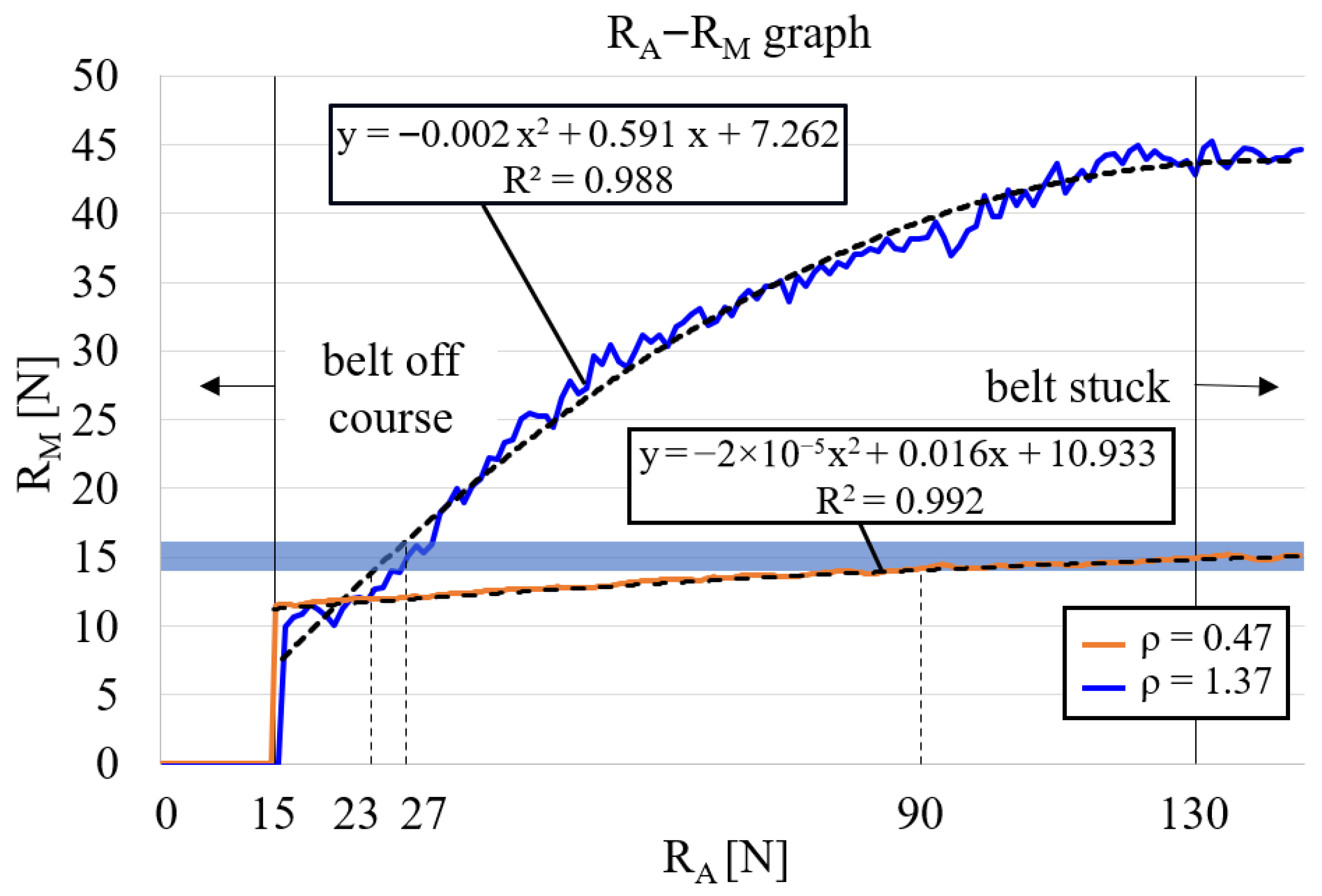
The relationship between
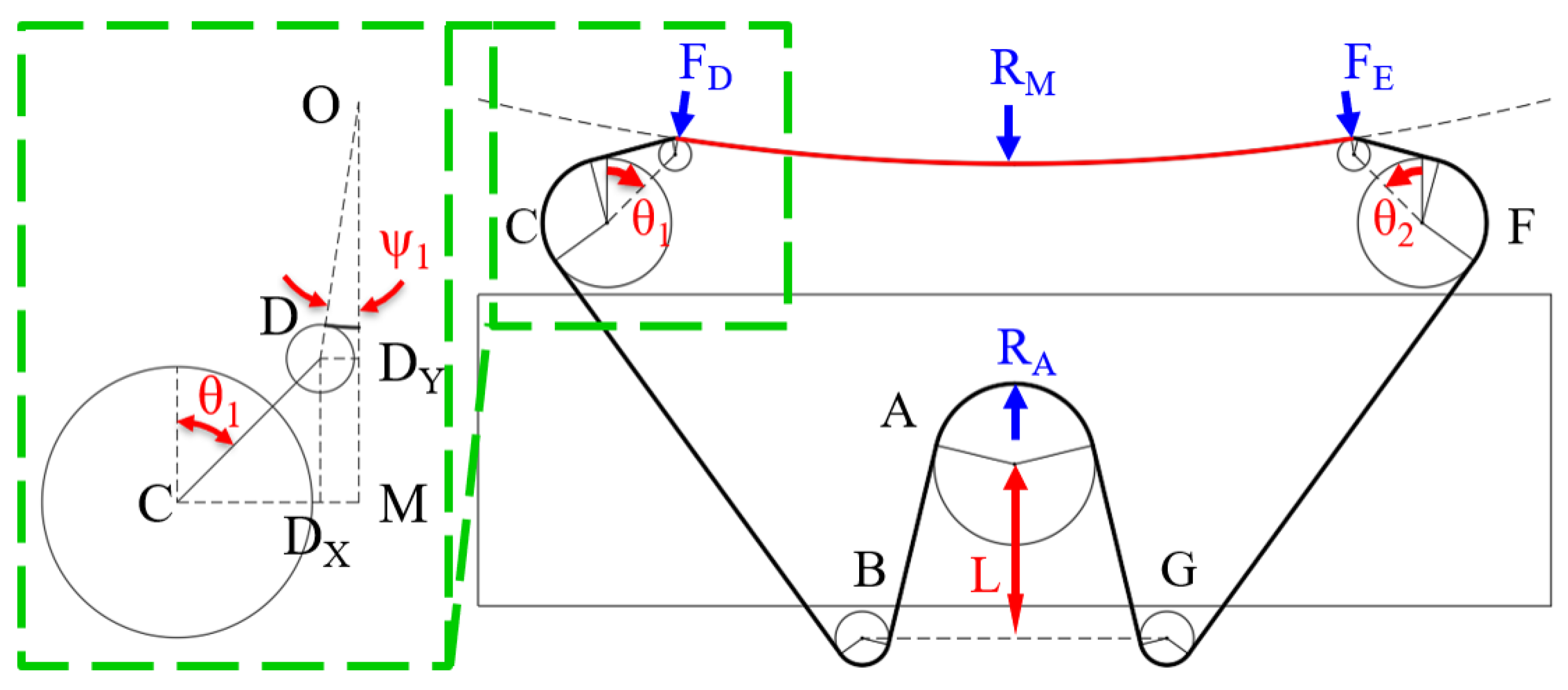
, which is the force exerted on the drive wheel by the belt tension, and
, which is the force at the midpoint of the target surface from the belt tension, was empirically determined, as shown in
Figure 10. There was insufficient tension on the belt to rotate when
was below 15 N, and the belt rotation was stopped because the tension was too high when
exceeded 130 N.
For each curvature, the mid-contact force
was fitted as a quadratic function of the drive wheel proxy
(both in newtons). The fitted relations are
where
denotes the curvature value used in the tests.
These second-order least-square fits are used within the observed operating range (
–130 N) reported in
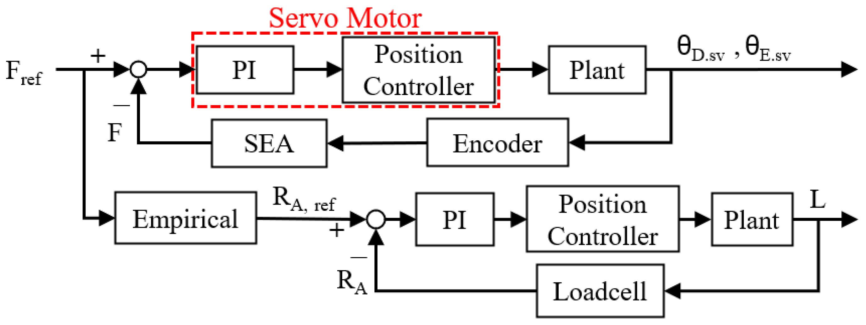
Figure 10. These relationship functions were chosen and used as an empirical block on the block diagram shown in
Figure 11.
The drive wheel proxy and mid-contact force were related by a quadratic fit, explicitly limited to the observed operating range . Although the number of sweeps per curvature was limited, the fits exhibited high quality and the residuals were approximately zero-mean without systematic trends. The mapping was then used as the reference-generation block in the control architecture, and its consistency was verified in subsequent closed-loop experiments using independent load cell measurements at points D, M, and E. Within the stated range, the mapping provides practically sufficient accuracy for reference generation.
The control of the force acting on the contact point on the SEA arm with the target surface and the PI control applied to the BLDC motor that controls
L (the distance between the re-tensioner adjuster and the center of the drive motor) follows the form shown in
Figure 11. The belt tension reference
was obtained from the empirical
map in
Figure 10 and applied within its observed range. Using this reference, PI control was executed while the achieved forces were assessed by the load cells at D, M, and E; the measurements track the targets under the stated operating conditions.
The force–control loops are designed for quasi-static regulation rather than broadband interaction. In the proposed mechanism, the effective contact stiffness is high but the arm deflections are small, which therefore generates large reaction forces. To avoid exciting structural and belt dynamics, proportional and integral gains were intentionally kept small, yielding a low closed-loop bandwidth relative to the dominant mechanical time constants and to the digital sampling rate. In addition, the series elastic elements reduce the reflected output impedance of the arms and attenuate high-frequency dynamics at the belt–workpiece interface. Under these conditions, the controller operates in a conservative regime. The commanded corrections evolve slowly compared with the fastest plant modes, and the SEA compliance filters contact transients. Empirical step-response tuning produced fast but non-oscillatory tracking, and no limit cycles or chatter were observed during the sanding trials reported in
Section 4. The combination of high plant stiffness, small PI gains, SEA-induced compliance, and a control bandwidth chosen well below structural and belt resonances provides practical robustness for the operating conditions evaluated in this study.
4. Experiments
This study prioritizes mechanism characterization and feasibility of large-area convex sanding rather than full process optimization. All trials used roll paper of nominal width 50 mm with abrasive grit #100, and the vertical feed was held at 50 mm/min. The belt was driven by a DC motor at a commanded drive wheel speed of 300 rpm. Force regulation was validated with independent load cells at points D, M, and E under the reported conditions.
4.1. Lab Test-Bench
During the abrasion process, including sanding, the surface roughness of the target surface converges to a certain value under a controlled feed rate and force [
20]. This, along with the evenly distributed normal force, allowed the vertical movement of the robot to evenly cover the entire convex surface.
Figure 12 shows the target surface dimensions, which were selected to meet the standard outlined in the European Union’s ADR Agreement for the International Carriage of Dangerous Goods by Road, with a long axis diameter of at least 1.5 times the short axis diameter [
21].
Vertical motion was also incorporated into the large-area sanding process. The target height was set as twice the belt width to achieve uniform sanding across the entire target surface. A vertical speed of 50 mm/min was maintained constant throughout the sanding process with a sanding belt width of 50 mm, sanding the entire area for 1 min, mirroring the conditions of the vertically stationary sanding method. Uniform sanding is achieved when the target surface is evenly sanded vertically.
4.2. Results
Unlike a typical contact situation, where the two forces exerted on the target surface at the contact points with the SEA arm wheels D and E are the same () and the target surface is symmetric, becomes smaller than once the drive motor is initiated. This is because of the rotating belt and its direction, which makes larger than if the belt direction is opposite. Therefore, it is important to control the servo angles to maintain both and separately and actively. PI control was used to maintain the reaction forces measured on , , and at a reference force of N, while was selected from the empirical graph such that .
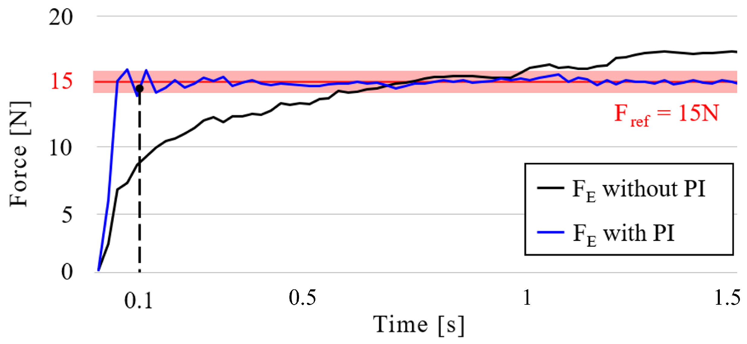
In the first case, without belt rotation, the force tracking ability between the SEA arm with and without PI control was measured.
was set to 0.3 for both the SEA arm and the re-tensioner, while
was set to 0.1 and 0.05 for the SEA arm and re-tensioner, respectively.
Figure 13 shows the forces measured at contact point E with and without PI control. As shown in the figure, a settling time of 0.096 s is observed for the PI-applied SEA arm, following a 4% error range around the reference force of 15 N. However, owing to the overlapped belt joint, vigorous vibration was inevitable even with a drive wheel of 300 rpm. Accordingly, a simple moving average (SMA) filter was used for evaluation, as in Duong et al.’s work [
22] for a vibration sensor application using (
10).
where
n is the window length and
is the
i-th sample of the measured force signal. Lotysh et al. [
23] and Zakamulin [
24] also expounded on the SMA and window or unit size effect.
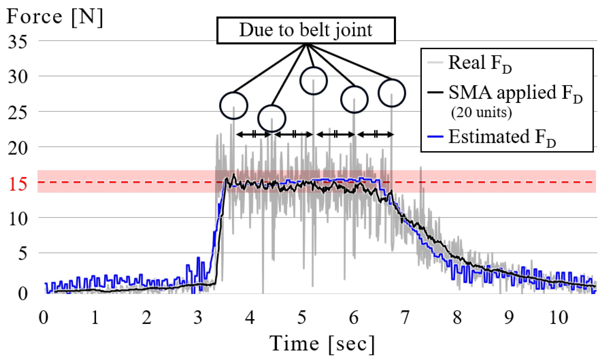
Figure 14 shows the force measured on contact point D with PI control and the SMA filter with 4% of the total number of samples—20 in this case—during belt operation. The belt joint generates equally spaced spikes in the force trace. To suppress this periodic component without distorting the low-frequency envelope, we use the simple moving average defined in Equation (
10) with a window of
(4% of samples). All quantitative metrics (peak force and settling time) are computed from the unfiltered signals, the SMA curve is for visualization only and therefore does not bias those estimates. The robot approached the target surface with the belt rotating and then departed from it after 4%. The time gaps between the sudden jumps in the graph are constant, indicating that this is owing to the overlapping part of the belt. The gray part represents the data measured on the target surface with the load cells, while the black line represents the same data filtered via SMA. The blue area represents the force exerted by the SEA arm. In this study, PI control is used to validate the SEA arm and re-tensioner architecture under the reported operating conditions; detailed controller optimization and stability-margin analysis are left for future work.
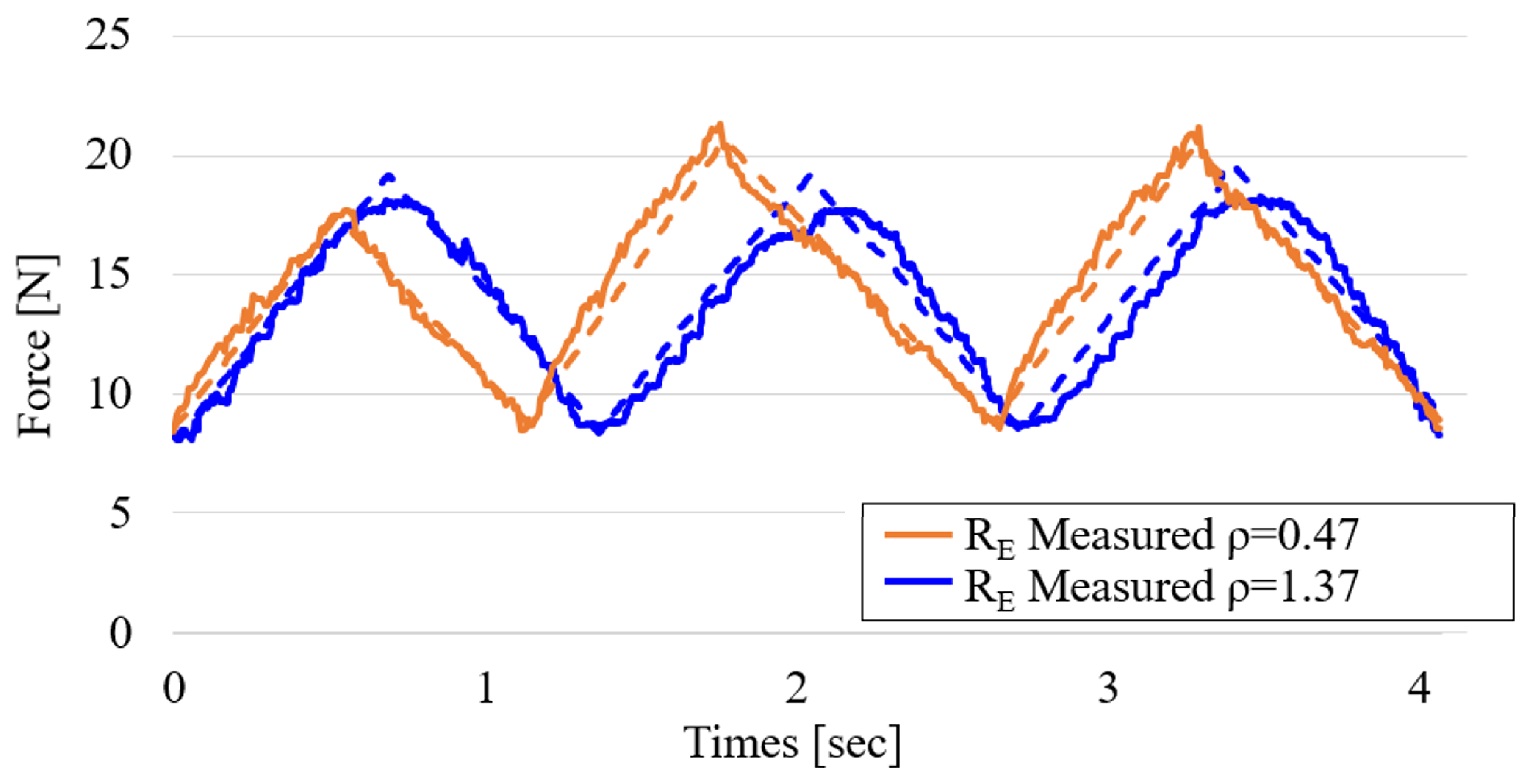
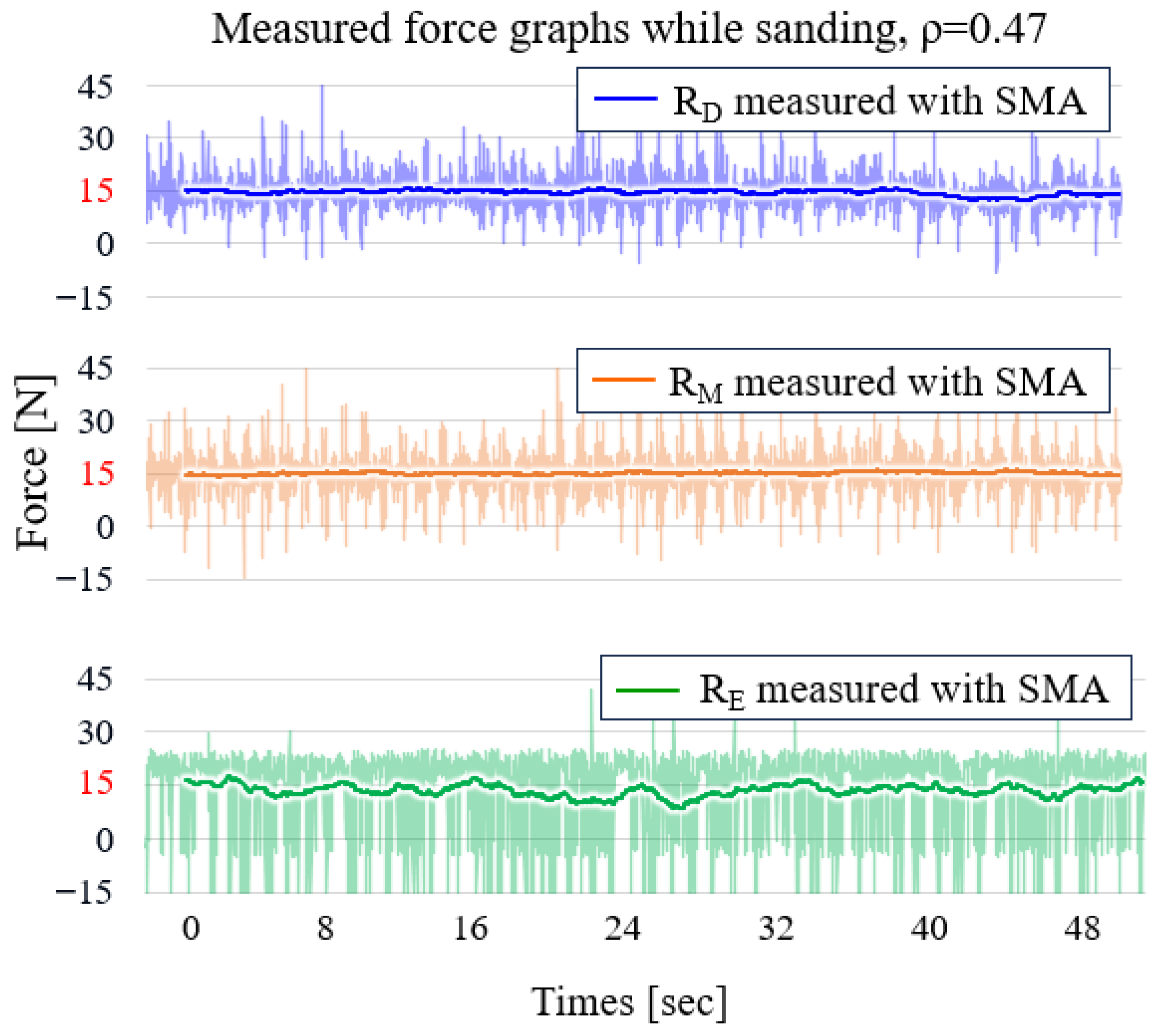
Figure 15 shows the reaction force measured on points D, M, and E on the target surface with a curvature of 0.47.
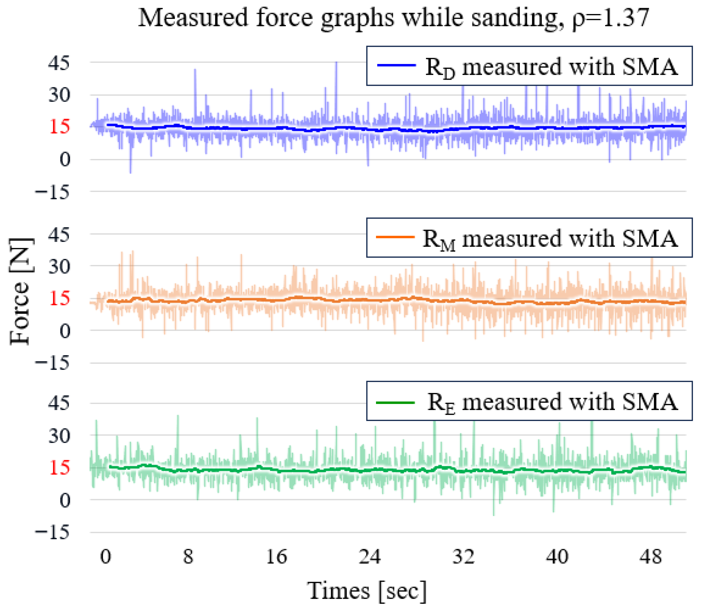
Figure 16 shows the same but for a target surface with a curvature of 1.37 during the sanding operation, with the same SMA window size percentage as before. These figures show that the force-tracking ability of
is superior to that of
. This is because of the belt rotation direction. For the SEA arm at point D, the belt moves in the direction that extends the spring while compressing the spring on the SEA arm at point E. However, because extension springs are used in this mechanism, the belt cannot be further compressed, making the force-tracking ability of the SEA arm at point E slightly inferior to that at point D.
Table 3 consolidates the operating and evaluation conditions used for the force-tracking results reported in
Figure 15 and
Figure 16.
4.3. Discussion
To verify the effectiveness of the proposed mechanism, the gaps in the maximum and minimum normal forces exerted on the plate during operation, as well as the finished quality evaluated with the vision system, were compared with those of a passive arm belt sanding robot in
Figure 17, which was used in a previous study. That robot has fixed idler and passive arm positions and cannot calculate any specific force on the target surface or itself. This imaging pipeline, including its latency considerations, is consistent with real-time inspection modules [
25].
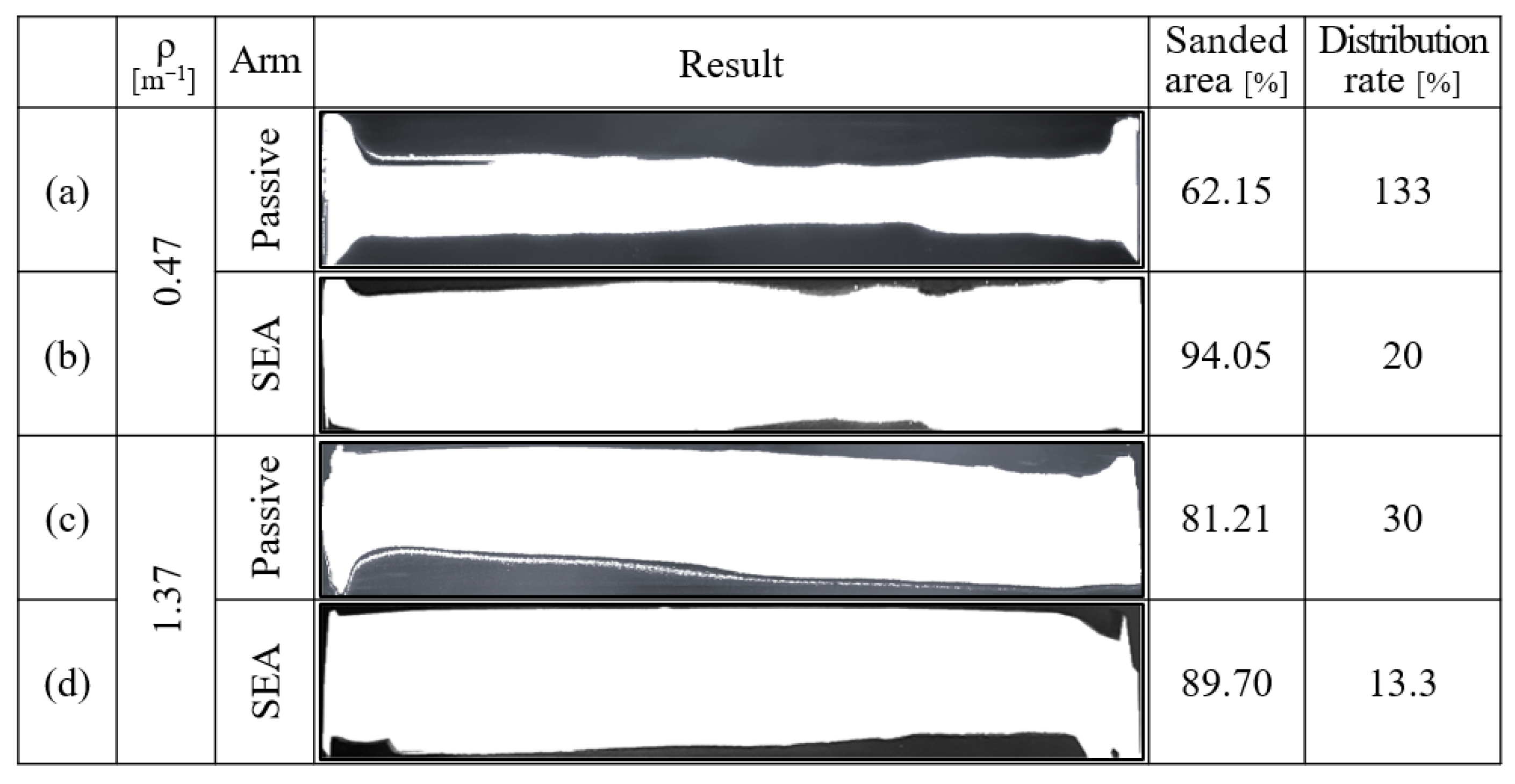
Figure 18 illustrates the vision inspection concept and process. The plate was first colored with a white primer and then black to show the sanded area edge, as the sanded surface reflects light, making it difficult to distinguish between the untouched and sanded surfaces. The finished surface was moved into a black jig to take the pictures, which were processed as described in a previous study, but in opposite colors. White represents the sanded area and black represents the opposite.
Figure 19 shows the vertical sanding process results with SEA and passive arms on each target surface. For the target surface with a curvature of 0.47, a 31.85% improvement in the sanded surface area was achieved, from 62.2% to 94.05%. For a target surface with a curvature of 1.37, an 8.49% improvement was achieved, from 81.21% to 89.7%.
The distribution rate, defined as the gap between the maximum and minimum normal forces exerted on the target plate throughout the contact area divided by the maximum force, was no less than 20% when the SEA arms were used. However, without a re-tensioner on the passive arm robot, even though having the same normal force on points D and E as 15 N was possible, the force at point M was unpredictable, ranging from 10 to N, because of the surface deformation caused by the high normal forces on D and E. This resulted in a distribution rate improvement of 113% and 16.7% for the 0.47- and 1.37-curvature target surfaces, respectively.
Under the operating conditions (belt width 50 mm and vertical feed 50 mm/min), the area rate for a single vertical pass is , i.e., . Force uniformity across the contact follows the distribution rate results already reported for the two convex curvatures (0.47 and 1.37) under identical settings. A principal limitation observed in the experiments is the compression asymmetry of the extension spring at wheel E, which slightly degrades tracking when the belt drives the spring into compression. A practical mitigation within the present mechanism is to select an appropriate spring preload and to implement asymmetric force loop gains between D and E. Although the – fit is validated by closed-loop performance within , statistical uncertainty will be quantified in future work after increasing the number of repeated sweeps.
