Article

Geometric Design and Basic Feature Analysis of Double Helical Face Gears

College of Mechanical Engineering and Automation, Liaoning University of Technology, Jinzhou 121000, China
*
Author to whom correspondence should be addressed.
Machines 2025, 13(10), 912; https://doi.org/10.3390/machines13100912
Submission received: 9 September 2025 / Revised: 29 September 2025 / Accepted: 1 October 2025 / Published: 3 October 2025
(This article belongs to the Section Machine Design and Theory)

Abstract

This study aims to address the problem that traditional helical gears generate significant axial forces during transmission and innovatively proposes a design scheme of double helical face gears (DHFG). An accurate mathematical model of the tooth surface is established using spatial meshing theory and coordinate transformation. A systematic investigation using the orthogonal test method is then conducted to analyze the influence of key parameters, such as the pinion tooth number, transmission ratio, and helix angle, on gear performance. The finite element analysis results show that the overlap degree of this double helical tooth surface gear pair in actual transmission can reach 2–3, demonstrating excellent transmission smoothness. More importantly, its unique symmetrical tooth surface structure successfully achieves the self-balancing effect of axial force. Simulation verification shows that the axial force is reduced by approximately 70% compared to traditional helical tooth surface gears, significantly reducing the load on the bearing. Finally, the prototype gear is successfully trial-produced through a five-axis machining center. Experimental tests confirmed that the contact impressions are highly consistent with the simulation results, verifying the feasibility of the design theory and manufacturing process.

1. Introduction

In recent years, the growing emphasis on lightweight automotive design and the rising demand for high power density transmissions in aerospace applications have imposed increasingly stringent requirements on the load-bearing capacity of face gears [1,2,3]. However, conventional helical face gears suffer from substantial axial forces, necessitating complex axial support structures and thereby limiting their broader application. To address these challenges, in-depth research on face gear design theory is critically needed to develop innovative gear pairs capable of effectively mitigating axial force issues.
Since the 1990s, considerable progress has been made in face gear research, spanning design, analysis, and manufacturing [4,5,6]. Litvin et al. [7,8,9] laid essential groundwork in gear meshing theory and contact analysis by systematically studying the meshing theory of face gear transmission and analyzing the distribution law of contact stress using computer simulation technology, thereby establishing the basis for the geometric modeling of face gears. However, their models largely addressed standard geometries without systematic consideration of axial force reduction. Subsequent studies have pursued specialized applications: Kawasaki et al. [10] optimized centering the performance in helical face gears by studying the assembly and positioning of helical gears in transmission systems, while Lin et al. [11] investigated a new type of eccentric herringbone curved surface gear compound motion mechanism for non-uniform transmission. Gao et al. [12] further proposed offset orthogonal arc-tooth designs to extend application ranges. Although innovative, these approaches offer limited solutions for axial force cancelation under high-load conditions.
In axial force and meshing optimization, researchers have sought to improve transmission performance. Mo et al. [13] established tooth modification principles by proposing two limit linearity principles for orthogonal surface gear transmission, providing a theoretical basis for tooth surface modification. Fu et al. [14,15] optimized contact characteristics through innovative insights on the design and analysis of gear pairs with modified tooth surfaces. Wang et al. [16] proposed a new analytical model for calculating the meshing duration of tooth pairs of orthogonal surface gears, determining the contact path based on the spatial position of contact points and normal vector coincidence conditions. While these methods enhance contact performance, they operate within conventional design constraints and do not address the fundamental trade-off between the helix angle and axial force. Similarly, in strength analysis, Li et al. [17,18] developed stress calculation methods by evaluating the geometric characteristics of face gear teeth and analyzing tooth surface contact. Zhou et al. [19] studied load distribution and bending stress during meshing and proposed corresponding analysis methods. Zhu et al. [20] incorporated surface roughness into stiffness modeling by establishing a time-varying meshing stiffness calculation method for rough tooth surfaces. However, these analyses presume pre-existing gear geometries and do not explore design modifications for axial force cancelation.
Recent advances in herringbone-type gears show promise for axial force management. Peng et al. [21] developed manufacturing methods for herringbone gears without tool withdrawal grooves, improving processing efficiency. Feng et al. [22,23] analyzed the relationship between tooth width and axial force through an in-depth study on the geometric design of herringbone toothed gears and their gear pairs. Mo et al. [24,25] further proposed asymmetric face gears with unequal pressure angles to increase tooth width and avoid tip pointing issues. Despite these innovations, a systematic design methodology for double helical face gears (DHFG) remains underdeveloped. This gap is particularly critical for high power density applications where both performance and structural efficiency are paramount.
The core of manufacturing double helical face gears lies in the precise forming of symmetrical tooth surfaces. The five-axis double-sided processing technology verified by Bo et al. [26] and Gomez-Escudero et al. [27], combined with Alvarez et al.’s [28,29] focus on surface quality control, is precisely the key to addressing this challenge.
The DHFG configuration addresses this limitation by integrating two symmetrical helical tooth surfaces to eliminate the net axial force, enabling larger helix angles while enhancing the load capacity. This study presents a comprehensive investigation into DHFG’s geometric design and fundamental characteristics with meticulous parameter optimization to meet demanding transmission requirements.

2. Materials and Methods

2.1. Pinion and DHFG Processing Materials

The gear pair in this study consists of the driving gear (pinion) and the driven gear (DHFG). The selection of all materials is based on the requirements for contact fatigue strength and bending fatigue strength under high-speed and heavy-load working conditions.
The driving wheel adopts 20CrMnTi alloy structural steel (conforming to GB/T 3077-2015 standard), and its supply state is a hot-rolled bar. This material has undergone carburizing, quenching, and low-temperature tempering treatment. The final surface hardness is 60 ± 2 HRC, the core hardness is 40 ± 5 HRC, and the effective carburized layer depth is 1.2 mm. Its core mechanical performance parameters are shown in Table 1. This material exhibits excellent carburizing performance and high fatigue strength, owing to which it is widely used in the manufacture of high-speed and heavy-duty gears.
The driven wheel DHFG is manufactured from 18CrNiMo7-6 carburized steel (in accordance with EN 10084) to ensure an optimal friction pair with the driving wheel. It undergoes the same heat treatment process as the driving wheel. The surface hardness is 58 ± 2 HRC, slightly lower than that of the driving wheel to balance the wear life of both. The effective hardened layer depth is 1.4 mm to adapt to its larger modulus. The specific performance parameters are shown in Table 1.

2.2. Geometric Design of DHFG Transmission Device

2.2.1. Pinion and Cutter Tooth Surface Equations

The tool gear is an involute helical cylindrical gear. The involute tooth profile of the tool is shown in Figure 1. The equation of the involute tooth profile of the tool is as follows:
x s θ s = r b s cos θ s + θ s 0 + θ s sin θ s + θ s 0 y s θ s = r b s ± sin θ s + θ s 0 θ s sin θ s + θ s 0 z s θ s = 0
where r b s is the base circle radius of the tool involute; θ s 0 is the angle parameter of the intersection point of the involute of the tool and the base circle, θ s 0 = π / ( 2 N s ) i n v α s ; θ s is the angle parameter of the involute tooth surface; N s is the number of teeth of the tool; α s is the pressure angle of the division circle phase of the cutting tool; i n v α s is the involute function, i n v α s = tan α s α s ; and ± corresponds to the tooth surfaces on both sides of the tool.
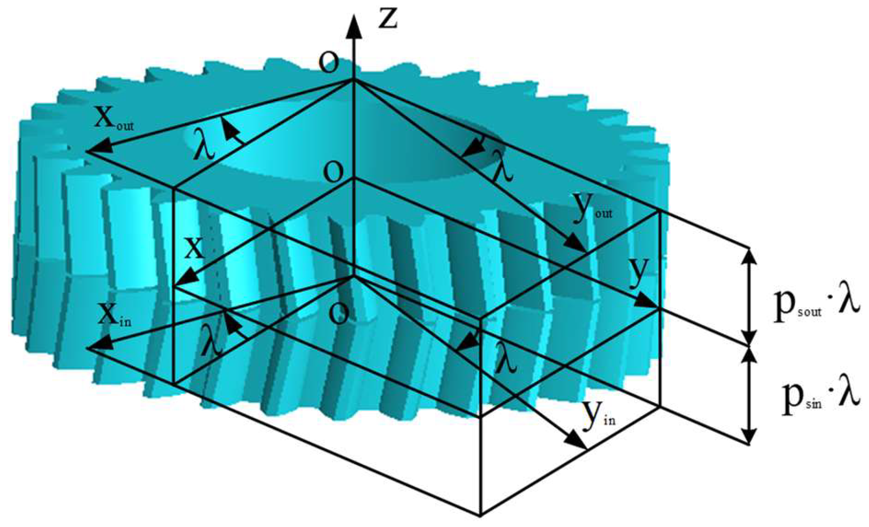
As shown in Figure 2, the tool performs a helical motion along the z s axis, where λ s represents the helical angle of the helical motion and p s is the helical parameter. Then, the tooth profile and tooth surface equations r sout and r sin of the two involute teeth involved in the helical motion can be expressed as follows:
x sout λ s , θ s = r bs cos θ s + θ s 0 λ s + θ s sin θ s + θ s 0 λ s y sout λ s , θ s = r bs ± sin θ s + θ s 0 λ s θ s cos θ s + θ s 0 λ s z sout λ s = p sout λ s
x sin λ s , θ s = r bs cos θ s + θ s 0 λ s + θ s sin θ s + θ s 0 λ s y sin λ s , θ s = r bs ± sin θ s + θ s 0 λ s θ s cos θ s + θ s 0 λ s z sin λ s = p sin λ s
Formula (1) describes the two-dimensional involute tooth profile of the cutting tool on the end section. Formulas (2) and (3) represent the three-dimensional tooth surface formed by the sweeping of the tooth profile after it moves helically along the tool axis by introducing the parameter φ.

2.2.2. Establishment of a Coordinate System for the Transformation of Face Gear

The DHFG is processed by the spatial development method. The tooth surface of the DHFG is formed by enveloping the tool surface as it moves through space along the given trajectory. Therefore, the tooth surface equation of a DHFG can be obtained by transforming the coordinate system through the tooth surface equation of the cutting tool in space.
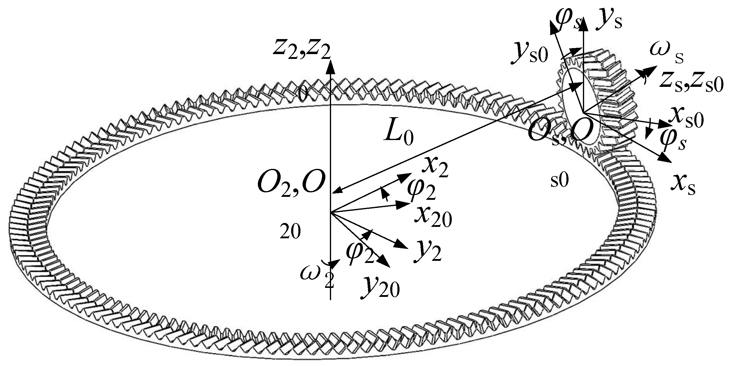
To derive the tooth surface equation, this study establishes four coordinate systems in Figure 3. Among them, two fixed systems, denoted as S s 0 x s 0 , y s 0 , z s 0 and S 20 x 20 , y 20 , z 20 , correspond to the initial positions of the tool gear and the DHFG. S s x s , y s , z s and S 2 x 2 , y 2 , z 2 are motion coordinate systems, which are rigidly and fixedly connected to the tool gear and the DHFG, respectively. The axis of the gear tool gear is in alignment with the z s axis and rotates around it at an angle of φ s , while the axis of the DHFG is in alignment with the z 2 axis and rotates around it at an angle of φ 2 .
Equations (4)–(6) are the coordinate transformation matrices between each coordinate system, where M s 0 , s represents the transformation from coordinate system S s x s , y s , z s to coordinate system S s 0 x s 0 , y s 0 , z s 0 , and so on for the others.
M s 0 , s = cos φ s sin φ s 0 0 sin φ s cos φ s 0 0 0 0 1 0 0 0 0 1
M 20 , s 0 = 0 0 1 L 0 0 1 0 0 1 0 0 0 0 0 0 1
M 2 , 20 = cos φ 2 sin φ 2 0 0 sin φ 2 cos φ 2 0 0 0 0 1 0 0 0 0 1
M 2 , s = M 2 , 20 M 20 , s 0 M s 0 , s = sin φ 2 sin φ s sin φ 2 cos φ s cos φ 2 L 0 cos φ 2 cos φ 2 sin φ s cos φ 2 cos φ s sin φ 2 L 0 sin φ 2 cos φ s sin φ s 0 0 0 0 0 1

2.3. Derivation of DHFG Tooth Equation

According to the principle of spatial expansion, the cutting tool and the face gear mesh in space and perform rotational motion. Based on the meshing principle, the meshing equation can be obtained:
n s v s ( s 2 ) = 0
where n s is the normal vector to the teeth of the tool, and v s ( s 2 ) is the velocity of the tool in the S s coordinate system with respect to the gear of the teeth.
Meshing Equation (8) defines the fundamental condition in gear theory: at the contact point, the common normal vector must be perpendicular to the relative velocity vector of the mating surfaces.
The derivation begins with the relative velocity at the contact point between the cutter gear and the generated face gear. At an arbitrary instant of contact point L, its velocity vector in the coordinate system is expressed as follows:
v s = ω s × r s
where ω s is the angular velocity of the cutter, and r s is the position vector of point L in the cutter coordinate system. In the face gear coordinate system S 2 , the kinematic relationship can be determined through coordinate transformation matrices as follows:
r 2 = M 2 , s r s
Assuming the angular velocity of the face gear is ω 2 , the velocity vector of contact point L in the face gear coordinate system S 2 can be expressed as follows:
v 2 = ω 2 × r 2
Assuming the cutter gear rotates with a unit angular velocity, it can be expressed as follows:
ω s = ( 0 , 0 , 1 ) T
The transmission ratio i 2 s of the face gear pair can be expressed as follows:
i 2 s = ω 2 ω s
The relative velocity of point L, resulting from its motion with respect to both coordinate systems S s and S 2 , can be expressed as follows:
v s ( s 2 ) = v s v 2 = ω s ¯ ω 2 ¯ × r s + ω 2 × O a O 2
Through derivation and simplification, the coordinate components of the relative velocity vector v s ( s 2 ) can be expressed as follows:
v s ( s 2 ) = v s x ( s 2 ) v s y ( s 2 ) v s z ( s 2 ) = y s i 2 s sin φ s z s L 0 i 2 s sin φ s x s i 2 s cos φ s z s L 0 i 2 s cos φ s i 2 s sin φ s x s + i 2 s cos φ s y s
The normal vector at meshing contact point L can be expressed as follows:
n s = r s λ s × r s θ s = i j k x s λ s y s λ s z s λ s x s θ s y s θ s z s θ s = n x s i + n y s j + n z s k
The components of the normal vector n s along the coordinate axes can be expressed as n s x , n s y , and n s z , represented by the following expression:
n s x = y s λ s z s λ s y s θ s z s θ s
n s y = z s λ s x s λ s z s θ s x s θ s
n s z = x s λ s y s λ s x s θ s y s θ s
Thus, the unit normal vector can be expressed as follows:
n ¯ s ( θ s , λ s ) = n s n s = n s n s x 2 + n s y 2 + n s z 2 = ± cos β b sin α cos β b cos α sin β b
where α = θ s + θ s 0 λ s , β b is the helix angle of the base circle, tan β b = r b s / p s .
Based on the principles of spatial gear meshing theory, substituting Equations (15) and (20) into (8) and simplifying yields the meshing equation f λ s , θ s , φ s as follows:
f λ s , θ s , φ s = i 2 s cos β b cos α ± φ s p s λ s r b s i s sin β b sin φ s ± α r b s cos β b r b s i 2 s sin β b sin α sin φ s cos α cos φ s + L 0 i 2 s cos β b cos α ± φ s
Applying the spatial transformation matrix converts the cutter’s tooth surface equation from system S s to S 2 , generating a family of surfaces during the simulated cutting motion. Consequently, the tooth surface equations for both sides of the DHFG can be expressed as follows:
r 2 in / 2 out λ s , θ s , φ s = M 2 s φ s r sin / sout λ s , θ s
f λ s , θ s , φ s = 0
Equation (22) gives the coordinates of a point on the face gear tooth surface, while Equation (23) implicitly incorporates the meshing condition to ensure the point is part of the valid contact surface.
For any point on the tooth surface to be valid, it must satisfy the meshing equation, ensuring the relative velocity vector and the unit normal vector at the contact point remain mutually perpendicular.

2.4. Modeling of DHFG

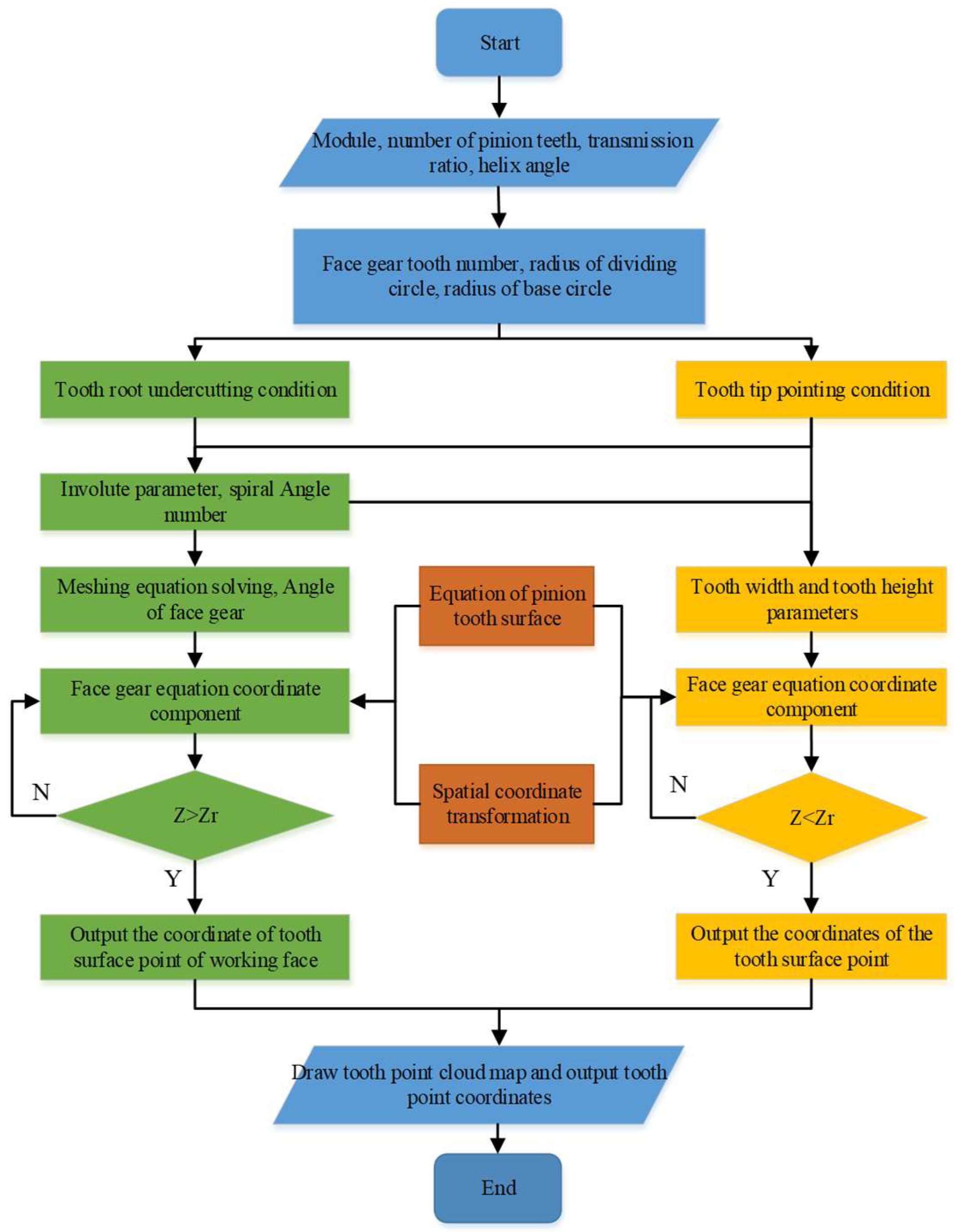
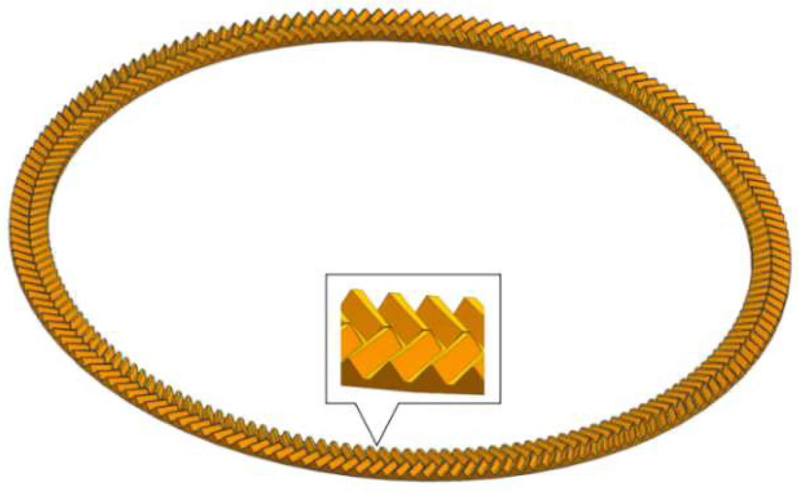
The parameters of the DHFG transmission model are shown in Table 2. Based on the above derivation process, the MATLAB 2021 program is written according to the flow shown in Figure 4 to generate the point cloud of DHFG pairs and establish the DHFG pair model, as shown in Figure 5.

2.5. DHFG Loading Contact Analysis Orthogonal Experimental Design

The application of orthogonal theory and mathematical statistics, through the design of orthogonal arrays, enables a substantial reduction in the number of tests. This strategy effectively lowers costs and enhances efficiency while ensuring the results remain representative.
This study employs an orthogonal experimental design to optimize the axial force in the DHFG and analyze the effects of selected factors on contact patterns, meshing stiffness, transmission errors, and contact stress. Based on the existing experimental data, three levels are taken for each factor: the number of teeth of the pinion is 25, 30, and 35; the transmission ratio is 6, 8, and 10; and the helix angle is 20°, 25°, and 30°. A set of blank groups is used as the error group. Based on this, a four-factor and three-level table is listed, and the selected orthogonal design is shown in Table 3. The factors are listed in sequence, and the levels are matched accordingly. A four-factor and three-level table, as listed in Table 4, is established, with a total of 9 groups of experiments designed.

3. Results

3.1. Simulation Model Simplification

Leveraging the meshing periodicity of DHFG pairs, a reduced-tooth model is adopted for the finite element analysis to balance computational accuracy and efficiency. As shown in Figure 6, a six-tooth segment model is used, which not only significantly lowers computational costs but also accurately captures the dynamic meshing behavior.
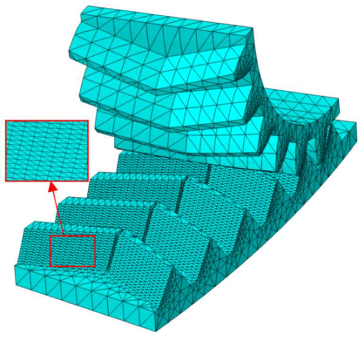
The finite element model employs tetrahedral elements, with a local seed number of 14 in the contact region and a global size of 5.45 mm to ensure accuracy (Figure 6). The final mesh contains approximately 18,000 elements for the DHFG and 31,000 for the pinion. The tooth surface interaction is modeled as surface-to-surface contact with a penalty algorithm (friction coefficient = 0.08). The pinion shaft is subjected to a rotational displacement, while the gear shaft is fixed in translation and loaded with a torque, accounting for geometric nonlinearity with convergence based on residual force. A mesh sensitivity analysis confirms the strategy’s adequacy, as further refinement changes the maximum contact pressure by less than 2%.
Additionally, since DHFG manufacturing without tool retreat grooves is complex, this study adopts a gear design incorporating such grooves. This design simplifies the machining process, thereby avoiding any degradation of tooth surface accuracy due to residual stresses.

3.2. Tooth Surface Contact Analysis

The finite element model of the six-gear pair is imported into ABAQUS for analysis and calculation to obtain the contact stress cloud map of the entire model.
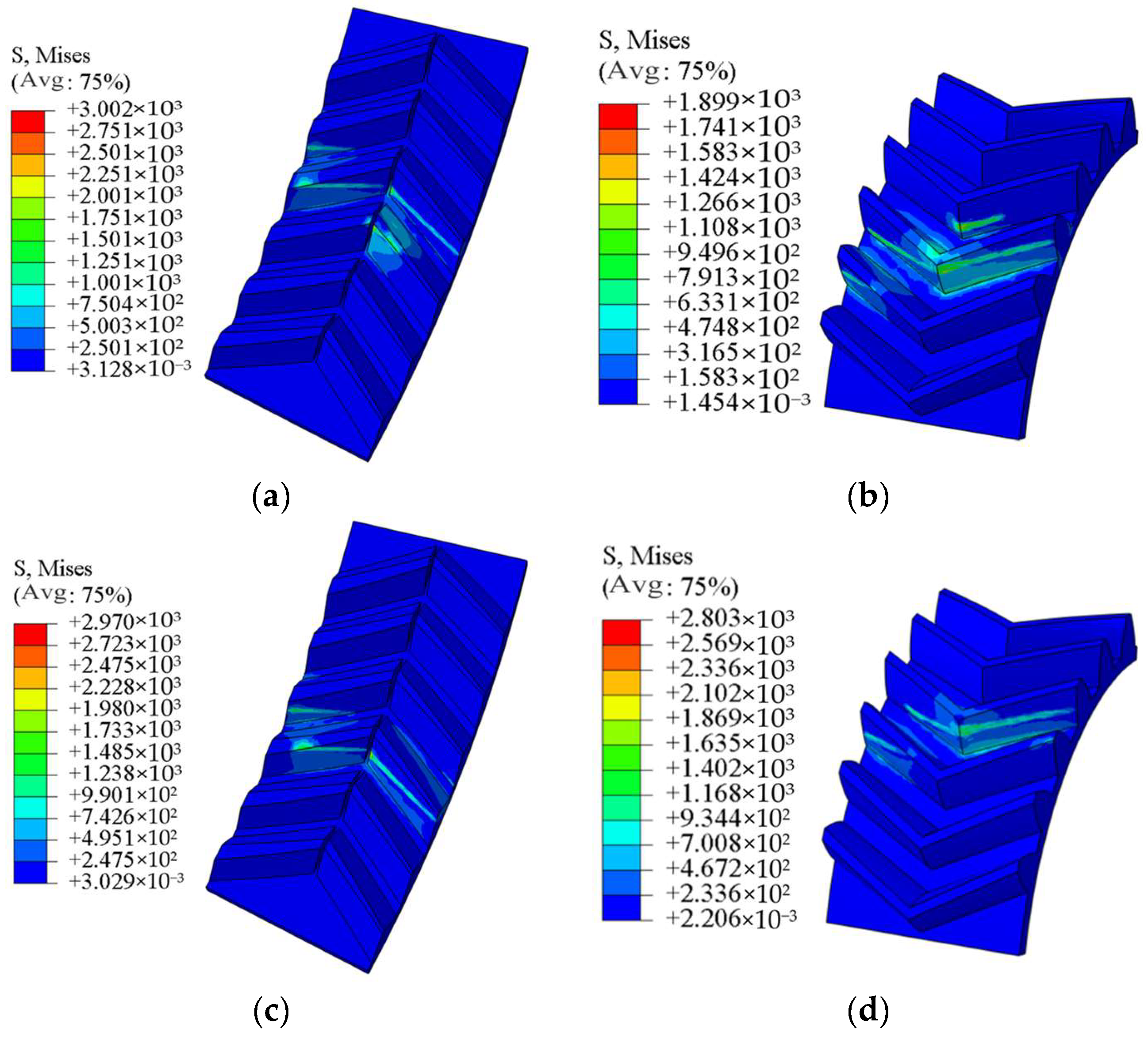
Taking Trial 4 as an example, Figure 7a,b present the calculated contact patterns of the DHFG pair at a specific meshing position. At this meshing position, three pairs of teeth are simultaneously engaged. The corresponding contact patterns are shown in Figure 7a,b. In contrast, Figure 7c,d present the contact patterns calculated at a different meshing position. At this meshing position, there are two pairs of gear teeth participating in meshing simultaneously. Through the observation of three meshing cycles, it is found that the number of meshing tooth pairs alternated periodically between two and three pairs, indicating that the actual overlap degree of this gear pair is between two and three. Further analysis of Trials 1–9 indicates that all overlap degrees fall within this range and exhibit an upward trend with an increasing pinion tooth count, transmission ratio, and helix angle.

3.2.1. Simulation Analysis of Meshing Stiffness

The time-varying meshing stiffness is computed in ABAQUS by solving for the tooth surface deformation under applied loads and boundary conditions, with the stiffness derived from the force–deformation ratio, as shown in Figure 8.
During the meshing process of the two gears, the meshing stiffness gradually decreases first and then increases. The meshing stiffness falls within the range of 0.5 × 10 4 N/mm to 2.5 × 10 4 N/mm for Trials 1, 4, 7, and 8; between 3 × 10 4 N/mm and 6.5 × 10 4 N/mm for Trials 2, 3, and 5; and between 10 × 10 4 N/mm and 30 × 10 4 N/mm for Trials 6 and 9. These results establish that the DHFG possesses a favorable meshing stiffness and load-bearing capacity, thereby supplying the essential stiffness parameters required for the subsequent transmission error analysis.

3.2.2. Transmission Error Analysis

Transmission error is the difference between the actual angular position reached by the driven gear at the current driving gear’s angular position and the theoretical angular position of the driven gear.
The transmission error over a full meshing cycle is quantified by calculating the actual angular displacement of the driven gear in ABAQUS under quasi-static conditions and then processing the results in MATLAB based on Equation (24):
Δ ϕ 2 = ϕ 2 ϕ 1 N s N 2
where ϕ 1 is the angular displacement of the pinion, ϕ 2 is the actual angular displacement of the DHFG, and ϕ 1 N s / N 2 represents the theoretical angular displacement of the driven gear when the angular displacement of the driving gear is ϕ 1 .
To compare the peak values across the nine trial groups, a common reference for the pinion’s initial rotation angle is established. The processing method is as follows: when the transmission error exhibits periodicity, the actual rotation angle of the DHFG is normalized relative to the minimum value of its periodic variation. Subsequently, a curve is plotted with the pinion’s rotation angle as the abscissa and the difference between the normalized actual angle and the theoretical angle (i.e., the transmission error) as the ordinate, as shown in Figure 9.
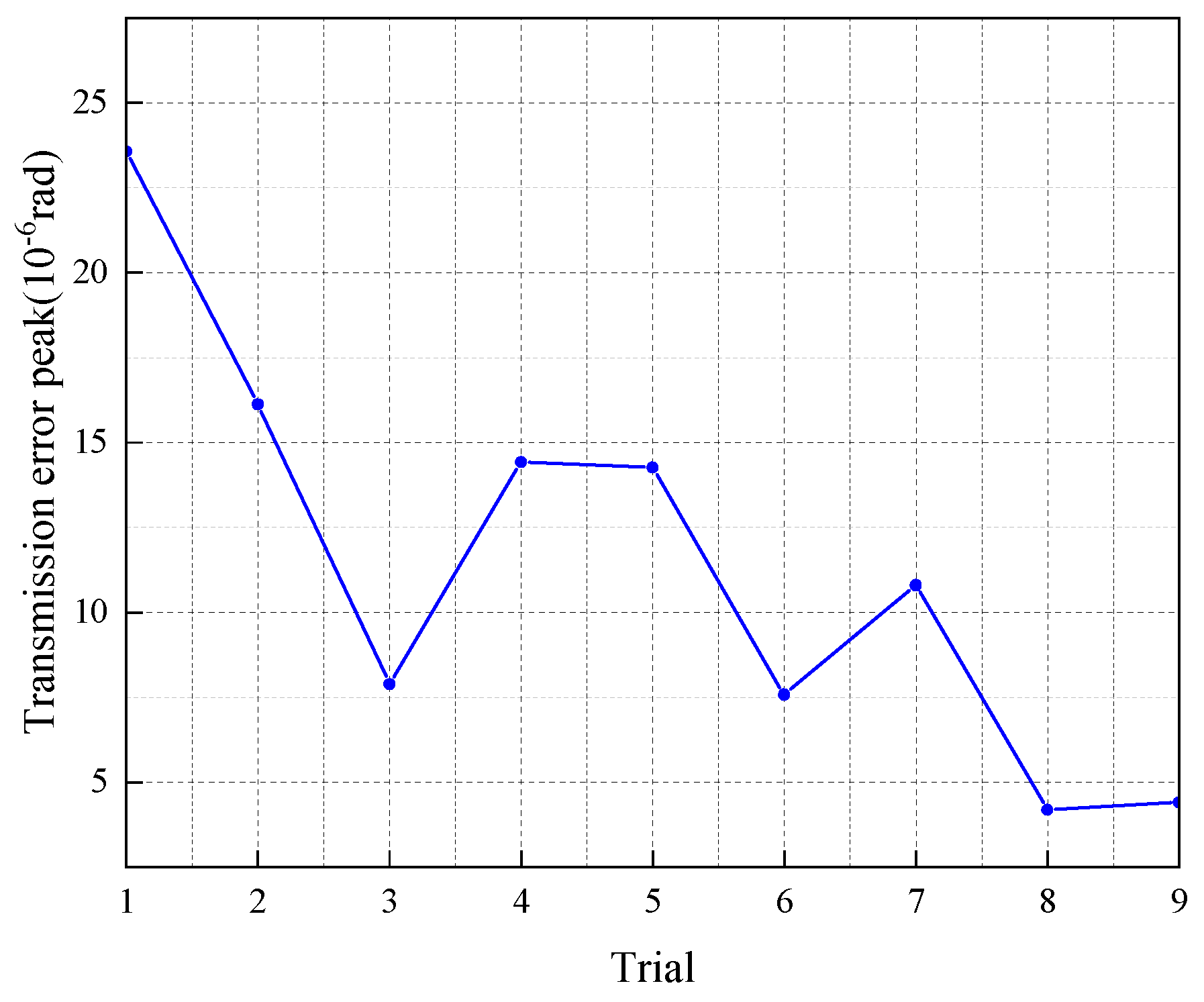
Figure 9 reveals that the DHFG transmission error displays periodicity during pinion rotation. The peak values for all trials are compared in Figure 10.
The data in Figure 10 support the conclusion that the transmission error decreases with increasing pinion tooth count, transmission ratio, and helix angle. This reduction in error contributes to lower vibration levels and improved operational smoothness.

3.2.3. Simulation Analysis of Contact Stress of DHFG

When the gear pair is operating under load, the meshing tooth surface will generate considerable contact stress due to the action of contact force. During the cyclic process of the gear pair continuously entering and exiting meshing, the contact stress presents a pulsating cyclic characteristic. Therefore, when the stress value exceeds the contact fatigue strength of the material, pitting damage often occurs on the tooth surface. Under real operating conditions, the contact stress magnitude is critical for gear longevity. Figure 11 investigates the stress analysis of the DHFG pair throughout the meshing cycle.
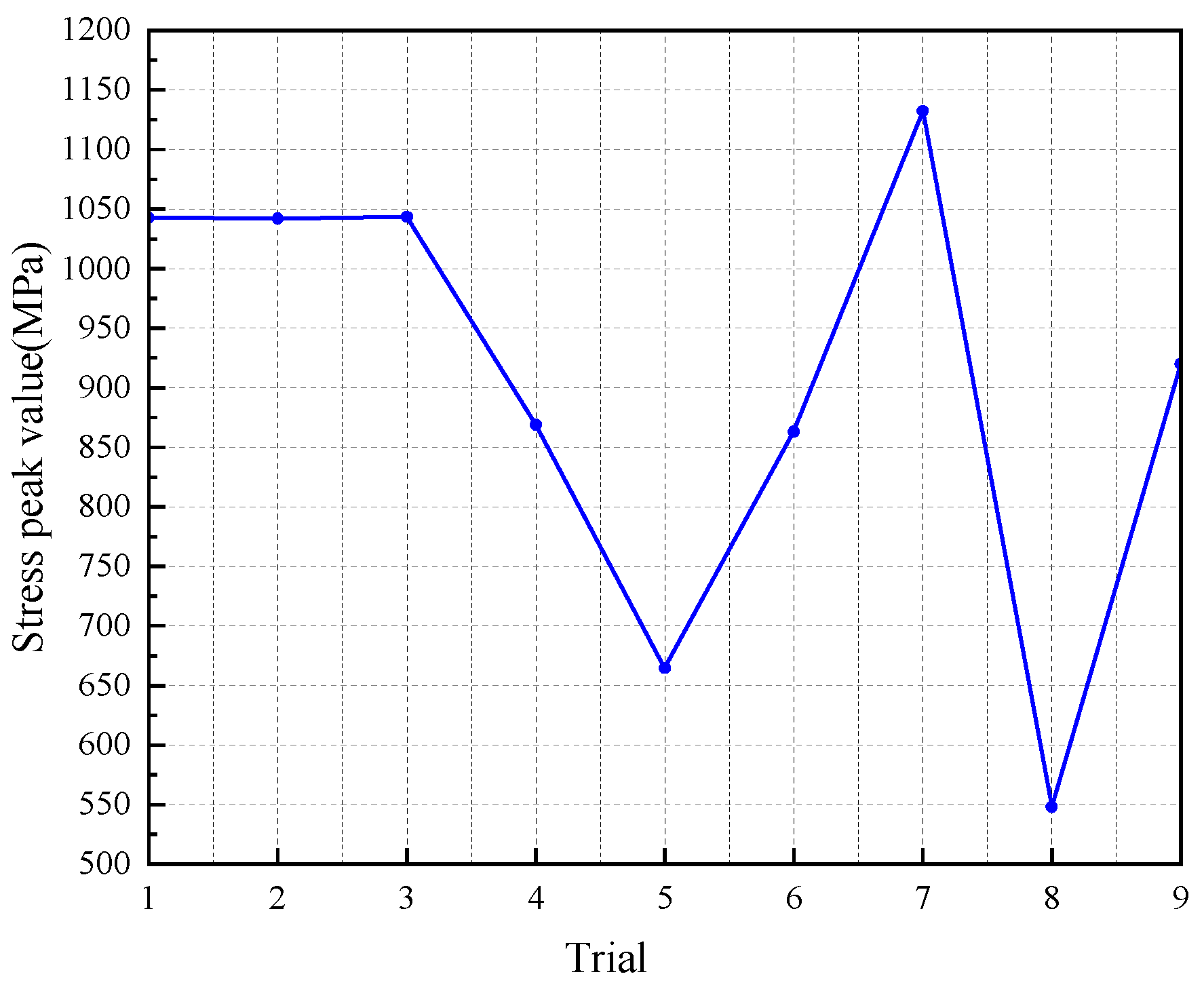
Figure 12 displays the stress peaks from Figure 11 for all trial groups. The stresses fall into two distinct ranges: 850–1150 MPa for Trials 1, 2, 3, 4, 6, 7, and 9, and 500–650 MPa for Trials 5 and 8. The trends of Trials 1 to 3 are basically stable, those of Trials 4 to 6 show a downward trend, and those of Trials 7 to 9 fluctuated greatly but generally showed a downward trend. Therefore, it can be initially concluded that, with the increase in the number of teeth, the transmission ratio, and helix angle of the pinion, the contact stress generally shows a downward trend, thereby reducing the risk of gear failure and improving the service life of gears.

3.3. Axial Force Analysis

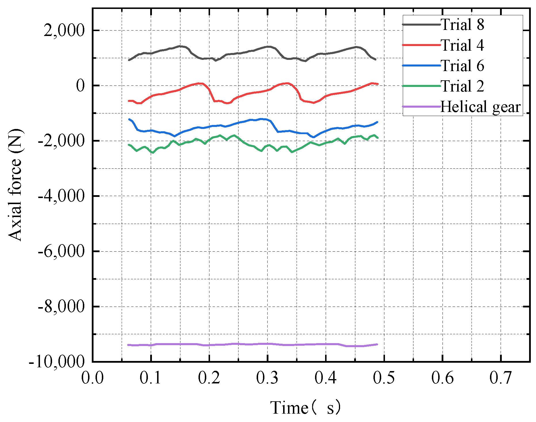
DHFGs achieve the self-balancing of axial forces through their unique symmetrical structure, significantly reducing the axial load compared to helical gears. To quantitatively analyze the axial force optimization effect, this section compares Trial Case No. 2, 4, 6, and 8 DHFG with a helical gear. The helical gear parameters are as follows: pinion teeth 30, helical gear teeth 180, helix angle 30°, pressure angle 20°, and shaft angle of 90°. The elastic modulus is E = 2.1 × 10 5   MPa , Poisson’s ratio is μ = 0.3 , and the torque is 532   N m . The ABAQUS finite element software is employed for load-contact analysis, with the resulting axial force data for both gear sets presented in Figure 13.
As shown in Figure 13, the DHFG generates a markedly lower axial force than its traditional counterpart, owing to the force-balancing effect of its symmetrical tooth design. The opposing axial force components from the left- and right-hand helices cancel each other out, thereby reducing the bearing load. The study further identifies 25° as the optimal helix angle, at which the axial force is minimized due to the most effective force balance.

3.4. Trial Manufacture for Geometric Design Method Verification

3.4.1. Experimental Study on the Machining and Manufacturing of DHFG

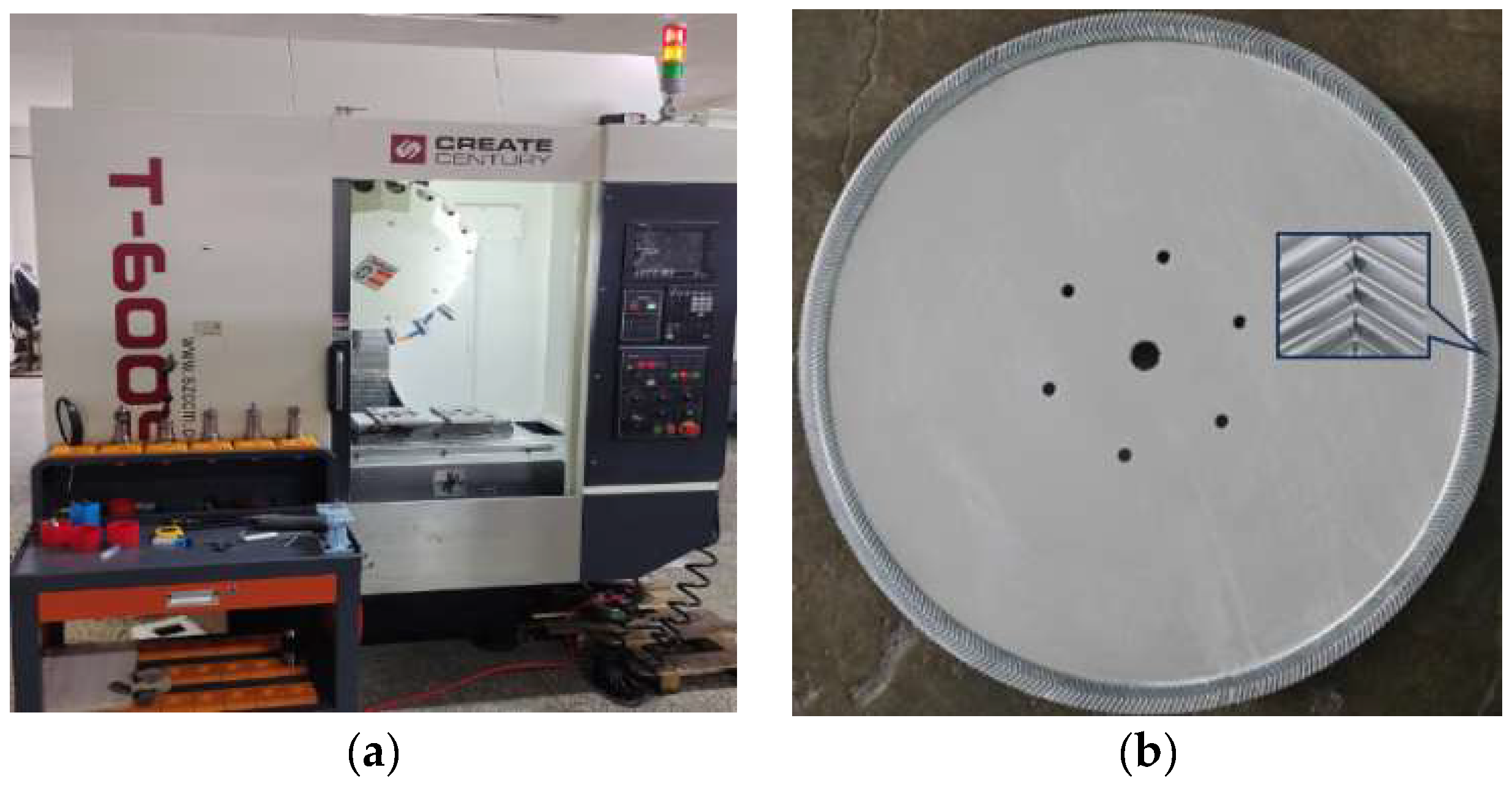
The T-600S drilling and milling center is utilized to machine the double helical face gear (DHFG) with a ball-end mill in a three-stage sequence: roughing, semi-finishing, and finishing, as illustrated in Figure 14a. During the roughing stage, the bulk material at the tooth tip and root is rapidly removed under high feed rates and deep cutting depths, leaving a uniform allowance for subsequent operations. The semi-finishing stage then refines the tooth surfaces with optimized spiral or contour-parallel toolpaths, reducing stepovers to correct geometric deviations and prepare for final machining. During finishing, the ball-end mill executes precision high-speed passes with minimal stepovers, completing the step-by-step refinement of the tooth surface to produce the final DHFG, as shown in Figure 14b.
The precision milling process employs climb milling, advanced coolant systems, and real-time CNC adjustments to effectively mitigate tool wear, vibration, and thermal distortion. Following machining, the gear undergoes deburring and rigorous inspection using CMMs and gear analyzers to validate the profile accuracy and surface quality, ultimately producing a high-precision DHFG that meets the requirements of demanding applications.

3.4.2. Contact Pattern Inspection of DHFG

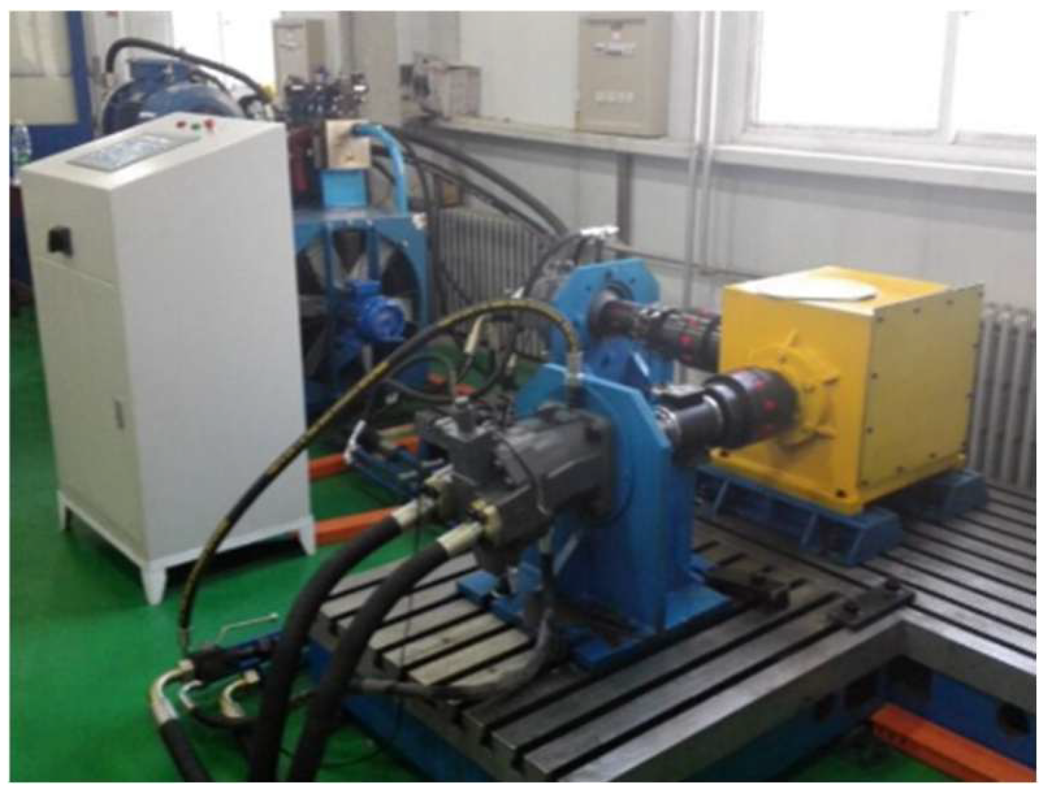
A dedicated test platform is developed for evaluating the DHFG performance, as illustrated in Figure 15. The platform consists of a face gear transmission system connected to a hydraulic pump and motor. The pinion is directly driven by the hydraulic pump, enabling the precise control of rotational speed and torque. The face gear is loaded through the hydraulic motor, with load torque regulated by an adjustable throttle valve. In this section, the DHFG of Test No. 4 is used for the experiment, with a torque of 532   N m and a rotational speed of 1500 rpm.
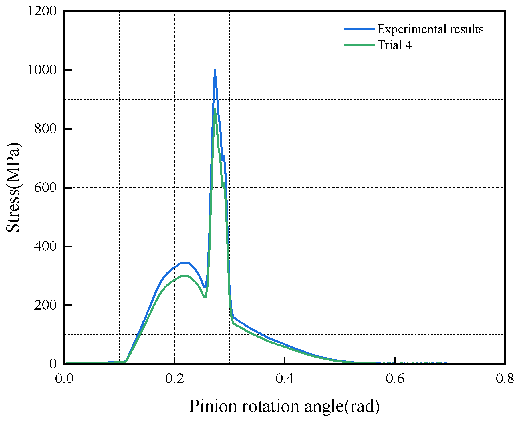
The simulation results show that Test 4 is the optimal design and exhibits superior performance in terms of axial force, stress, and transmission error. To verify this finding, experiments are conducted using the gear parameters from Trial 4. As shown in Figure 16 and Figure 17, the consistency between the simulation results and the experimental results is relatively high, confirming the accuracy and reliability of the finite element model.
The experimental contact patterns of the DHFG, obtained from the test platform, are presented in Figure 18a,b. The uniform distribution of red lead powder across the entire tooth surface demonstrates that different positions of each pinion tooth sequentially engage with the face gear during meshing. This observed meshing behavior shows excellent agreement with simulation results, thereby validating both the feasibility and geometric accuracy of the DHFG tooth profile design.

4. Conclusions

This study comprehensively investigated the design, manufacturing, and performance analysis of double helical face gears (DHFG) through an integrated approach, combining theoretical derivation, numerical simulation, and experimental validation. The main conclusions are summarized as follows:
  • A robust mathematical model for the DHFG tooth surface is established based on the spatial meshing theory and coordinate transformation. Point clouds on the surface of teeth are generated through computer programs to precisely create 3D models for subsequent finite element analysis.
  • The finite element analysis revealed that the designed DHFG pair exhibits favorable meshing characteristics. The actual overlap ratio fluctuated between two and three, ensuring smooth power transmission. Furthermore, the meshing stiffness results indicated a strong load-bearing capacity of the tooth surface.
  • The orthogonal experimental design effectively identified the influence of key design parameters (pinion tooth count, transmission ratio, and helix angle). The results demonstrated a clear trend: increasing these parameters generally reduced the transmission error (enhancing operational smoothness and reducing vibration) and decreased maximum contact stress.
  • The symmetrical double helical structure of the DHFG enables the inherent self-balancing of axial forces. Finite element analysis demonstrated a substantial reduction in axial load compared to a single helical gear. This advantage lowers the load requirements on bearings and housing, facilitating more compact and efficient transmission.
  • Excellent agreement between simulation and experimental results confirms the FE model’s reliability. This, combined with the successful prototype manufacture and correlation of its contact pattern with simulations, validates the entire design-to-manufacturing process.

Author Contributions

Conceptualization, X.C.; methodology, F.C.; software, F.C.; validation, X.C. and F.C.; formal analysis, X.C.; investigation, F.C.; resources, X.C.; data curation, F.C.; writing—original draft preparation, F.C.; writing—review and editing, X.C.; visualization, F.C.; supervision, X.C.; project administration, X.C.; funding acquisition, X.C. All authors have read and agreed to the published version of the manuscript.

Funding

This research was funded by the Natural Science Foundation Project of Liaoning Province (Grant No. 2025-MS-161), 2024 Fundamental Research Project (No. LJ212410154002) of the Educational Department of Liaoning Province, Basic Scientific Research Key Project of the Education Department of Liaoning Province (No. LJKZ0603), and Doctoral Research Start-up Fund Project of Liaoning Province (No. 2022-BS-308).

Data Availability Statement

The original contributions presented in this study are included in the article. Further inquiries can be directed to the corresponding author.

Acknowledgments

We would like to express our appreciation for the support provided by the research community, which has been instrumental in facilitating this work.

Conflicts of Interest

The authors declare no conflicts of interest.

Nomenclature

The following symbols are used in this article:
r b s The base circle radius of the tool involute
θ s 0 The angle parameter of the intersection point between the involute of the cutting tool and the base circle
θ s The angle parameter of the involute tooth surface
φ s The angle turned by the cutting tool during processing
N s The number of teeth of the tool
α s The pressure angle of the division circle phase of the cutting tool
i n v α s The involute function i n v α s = tan α s α s
λ s The helical angle of the helical motion
p s The helical parameter
n s The normal vector to the teeth of the tool
v s ( s 2 ) The velocity of the tool in the S s coordinate system with respect to the gear of the teeth
ω s The angular velocity of the cutter
r s The position vector of point L in the cutter coordinate system
β b The helix angle of the base circle
r p s The pitch circle radius of the tool gear
a f The root height of the tool gear
ϕ 1 The angular displacement of the pinion
ϕ 2 The actual angular displacement of the DHFG
ϕ 1 N s / N 2 The theoretical angular displacement of the driven gear

References

  1. Liu, H.; Zhao, J.; Tang, J. Simulation and Experimental Verification of Die Quenching Deformation of Aviation Carburized Face Gear. Materials 2023, 16, 690. [Google Scholar] [CrossRef]
  2. Mo, S.; Xuan, H.; Liu, W.; Zhang, W. Study on nonlinear vibration and primary resonance characteristics of helicopter face gear-planetary gear coupling transmission system. Proc. Inst. Mech. Eng. Part K-J. Multi-Body Dyn. 2023, 237, 534–550. [Google Scholar] [CrossRef]
  3. Chen, H.; Li, Q.; Jia, C. Research on the Design and Meshing Performance Analysis of Face Gear Meshing Nutation Reducers. Mathematics 2025, 13, 476. [Google Scholar] [CrossRef]
  4. Liu, D.; Wang, G. Transmission principle and geometrical model of eccentric face gear. Mech. Mach. Theory 2017, 109, 51–64. [Google Scholar] [CrossRef]
  5. Noritsugu, M. Research on simplification of face gear tooth surface design. J. Adv. Mech. Des. Syst. Manuf. 2024, 18, JAMDSM0006. [Google Scholar] [CrossRef]
  6. Wei, S.; Zhao, J. Geometric Design of a Face Gear Drive with Low Sliding Ratio. Appl. Sci. 2022, 12, 2936. [Google Scholar] [CrossRef]
  7. Litvin, F.L.; Fuentes, A. Gear Geometry and Applied Theory, 2nd ed.; Cambridge University Press: New York, NY, USA, 2004. [Google Scholar]
  8. Litvin, F.L.; Fuentes, A.; Zanzi, C. Design, generation, and stress analysis of two versions of geometry of face gear drives. Mech. Mach. Theory 2002, 37, 1179–1211. [Google Scholar] [CrossRef]
  9. Litvin, F.L.; Gonzalez-Perez, I.; Fuentes, A. Design, generation and stress analysis of face gear drive with helical pinion. Comput. Methods Appl. Mech. Eng. 2005, 194, 3870–3901. [Google Scholar] [CrossRef]
  10. Kawasaki, K.; Tsuji, I.; Gunbara, H. Geometric design of a face gear drive with a helical pinion. Mech. Sci. Technol. 2018, 32, 1653–1659. [Google Scholar] [CrossRef]
  11. Lin, C.; Ran, G.; Hu, Y. Compound motion characteristics analysis of eccentric herringbone curve-face gear pair. Mech. Sci. Technol. 2021, 35, 5571–5578. [Google Scholar] [CrossRef]
  12. Gao, L.; Feng, Z.R. Tooth surface design and undercutting research of offset orthogonal arc tooth face gear. J. Aerosp. Power 2022, 37, 869–876. [Google Scholar] [CrossRef]
  13. Mo, S.; Zhang, Y. Design methods and stress analysis of asymmetric offset face-gear transmission. Proc. Inst. Mech. Eng. Part C-J. Mech. Eng. Sci. 2022, 236, 7814–7828. [Google Scholar] [CrossRef]
  14. Fu, X.; Fang, Z.; Cui, Y. Modelling, design and analysis of offset, non-orthogonal and profile-shifted face gear drives. Adv. Mech. Eng. 2018, 10. [Google Scholar] [CrossRef]
  15. Fu, X.; Zhang, C.; Xu, H. Static load sharing performance of non-orthogonal and offset helical face gear dual-branch drivetrain. Adv. Mech. Eng. 2025, 17, 1–11. [Google Scholar] [CrossRef]
  16. Wang, J.; Dong, J.; Wang, S.; Xiao, Y. Mathematic design and computer analysis of curve-surface conjugated face gear pair. Adv. Mech. Eng 2025, 17, 1–13. [Google Scholar] [CrossRef]
  17. Li, Z.; Wu, H.; Zhu, R. Influence predictions of geometric parameters on face gear strength. Adv. Mech. Eng. 2015, 2015, 1–7. [Google Scholar] [CrossRef]
  18. Li, Z.; Fan, J.; Zhu, R. Construction of tooth modeling solutions of face gear drives with an involute pinion. Iran. J. Sci. Technol. Trans. Mech. Eng. 2018, 42, 35–39. [Google Scholar] [CrossRef]
  19. Zhou, W.; Zhu, R. Theoretical and experimental research on tooth root bending stress of face gear. Proc. Inst. Mech. Eng. Part C-J. Mech. Eng. Sci. 2024, 238, 7172–7188. [Google Scholar] [CrossRef]
  20. Zhu, L.; Bai, J.X. Stiffness analysis of nutation face gear considering roughness. Eng. Comput. 2023, 40, 2348–2362. [Google Scholar] [CrossRef]
  21. Peng, L. A new geometry definition and generation method for a face gear meshed with a spur pinion. Proc. Inst. Mech. Eng. Part B-J. Eng. Manuf. 2022, 236, 1037–1051. [Google Scholar] [CrossRef]
  22. Feng, G.; Gu, Y.P. Geometric design and characteristic analysis of herringbone face gears. Tsinghua Univ. 2019, 59, 670–678. [Google Scholar] [CrossRef]
  23. Feng, G.; Xie, Z.F.; Zhou, M. Geometric design and analysis of face gear drive with involute helical pinion. Mech. Mach. Theory 2019, 134, 169–196. [Google Scholar] [CrossRef]
  24. Mo, S.; Wang, S. Machining principle and cutter design of face gear skiving. Proc. Inst. Mech. Eng. Part B-J. Eng. Manuf. 2023, 237, 468–480. [Google Scholar] [CrossRef]
  25. Mo, S.; Luo, B.R. Geometry design and tooth contact analysis of non-orthogonal asymmetric helical face gear drives. Mech. Mach. Theory 2022, 173, 104831. [Google Scholar] [CrossRef]
  26. Bo, P.; González, D.; Kang, K.; Wu, Y.; Ma, W. 5-axis double-flank CNC machining of spiral bevel gears via custom-shaped milling tools—Part I: Modeling and simulation. Precis. Eng. 2020, 62, 204–212. [Google Scholar] [CrossRef]
  27. Gómez Escudero, G.; Bo, P.; González-Barrio, H.; Ortega, R.; López de Lacalle, L.N. 5-axis double-flank CNC machining of spiral bevel gears via custom-shaped tools—Part II: Physical validations and experiments. Int. J. Adv. Manuf. Technol. 2022, 119, 1647–1658. [Google Scholar] [CrossRef]
  28. Álvarez, A.; Calleja, A.; Ortega, N.; López de Lacalle, L.N. Spiral bevel gears face roughness prediction produced by CNC end milling centers. Materials 2018, 11, 1301. [Google Scholar] [CrossRef]
  29. Álvarez, A.; Calleja, A. Five-Axis Milling of Large Spiral Bevel Gears: Toolpath Definition, Finishing, and Shape Errors. Metals 2018, 8, 353. [Google Scholar] [CrossRef]
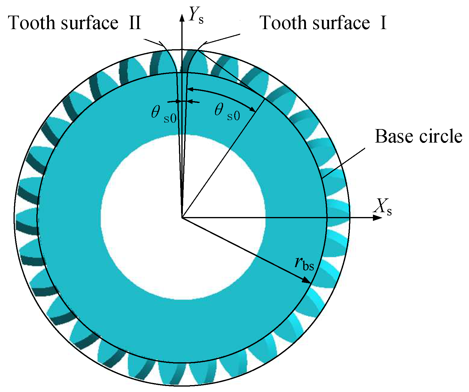
Figure 1. Involute tooth surface parameter.
Machines 13 00912 g001
Figure 2. Helical motion coordinate system.
Machines 13 00912 g002
Figure 3. Face gears unfolding into a transformed coordinate system.
Machines 13 00912 g003
Figure 4. Flowchart of the DHFG model.
Machines 13 00912 g004
Figure 5. Three-dimensional model of DHFG.
Machines 13 00912 g005
Figure 6. Finite element 6-tooth model for tooth surface contact analysis.
Machines 13 00912 g006
Figure 7. Contact analysis of DHFG pair meshing. Note: (a) Face gear with 3 pairs of meshing marks; (b) pinion gear with 3 pairs of meshing marks; (c) face gear with 2 pairs of meshing marks; and (d) pinion gear with 2 pairs of meshing marks.
Machines 13 00912 g007
Figure 8. Nine groups of meshing stiffness.
Machines 13 00912 g008
Figure 9. Nine-group orthogonal transmission error.
Machines 13 00912 g009
Figure 10. Peak-to-peak values of 9 groups of transmission errors.
Machines 13 00912 g010
Figure 11. Nine groups of DHFG stress.
Machines 13 00912 g011
Figure 12. Nine groups of DHFG stress peak trials.
Machines 13 00912 g012
Figure 13. Different parameters first involve axial force.
Machines 13 00912 g013
Figure 14. Trial manufacture of face gear for geometric design method verification. Note: (a) Drilling and milling machining center T-600S; (b) machined prototype of DHFG.
Machines 13 00912 g014
Figure 15. Face gear rolling test bench.
Machines 13 00912 g015
Figure 16. Comparison of contact stress between experiments and simulations.
Machines 13 00912 g016
Figure 17. Comparison of transmission errors between experiments and simulations.
Machines 13 00912 g017
Figure 18. Meshing contact marks of DHFG. Note: (a) Meshing marks of the pinion; (b) meshing marks of DHFG.
Machines 13 00912 g018
Table 1. Mechanical properties of gear materials.
Performance Parameters20CrMnTi (Pinion)18CrNiMo7-6 (DHFG)Unit
Surface hardness60 ± 258 ± 2HRC
Core hardness40 ± 538 ± 5HRC
Tensile strength (Rm)≥1500≥1200MPa
Yield strength (Rp0.2)≥950≥850MPa
Contact fatigue strength (σ Hlim)15001450MPa
Bending fatigue strength (σ Flim)430400MPa
Table 2. Parameters of DHFG transmission model.
Gear Parameter NameParameter Value
Number of pinion teeth30
Tooth number of DHFG180
Modulus (mm)5
Pressure angle (°)20
Tooth top height coefficient1
Top clearance coefficient0.25
Internal helix angle (°)−30
Outer helix angle (°)30
Table 3. Factor level table.
LevelNumber of
Pinion Teeth
Transmission
Ratio
Helix
Angle (°)
Blank Group
125620-
230825-
3351030-
Table 4. Orthogonal experimental scheme design.
TrialNumber of
Pinion Teeth
Transmission
Ratio
Helix
Angle (°)
Blank Group
11111
21222
31333
42132
52213
62321
73123
83231
93312
Disclaimer/Publisher’s Note: The statements, opinions and data contained in all publications are solely those of the individual author(s) and contributor(s) and not of MDPI and/or the editor(s). MDPI and/or the editor(s) disclaim responsibility for any injury to people or property resulting from any ideas, methods, instructions or products referred to in the content.