Novel Model Predictive Control Strategies for PMSM Drives: Reducing Computational Burden and Enhancing Real-Time Implementation
Abstract
1. Introduction
2. System Modeling
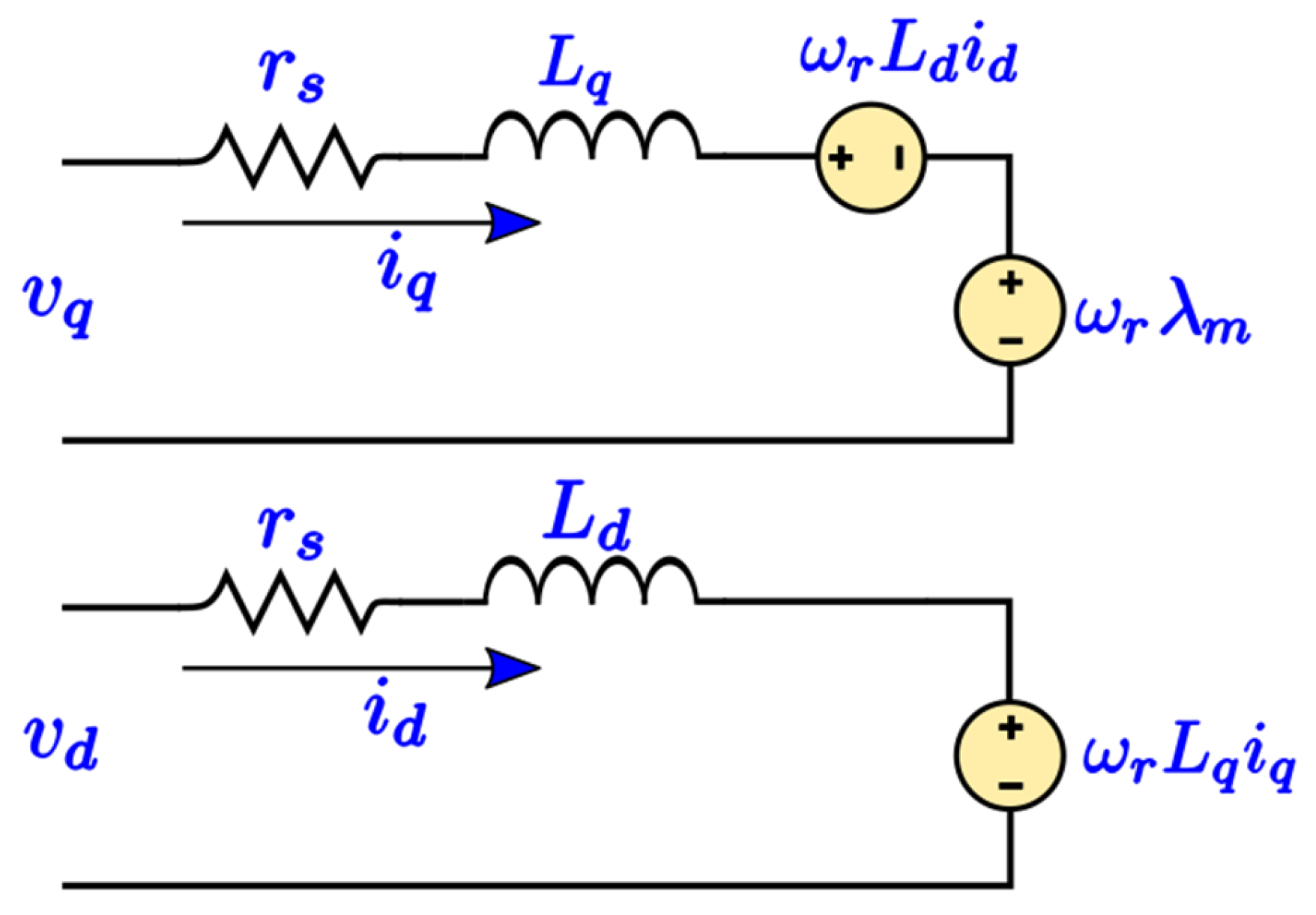
2.1. PMSM Modeling
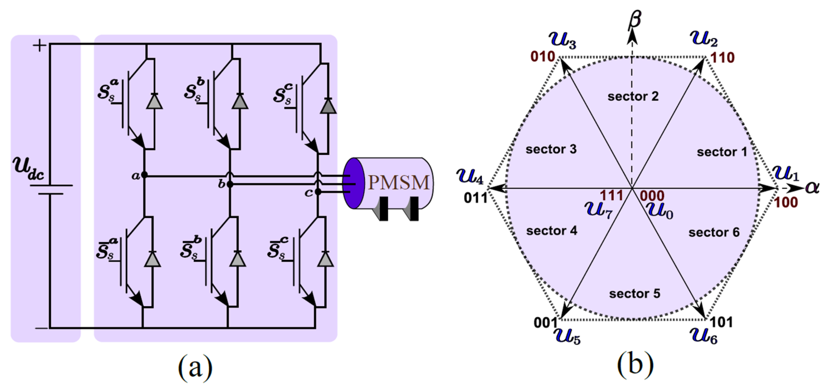
2.2. Inverter Model
3. Conventional Algorithms for Control PMSM
3.1. Conventional MPCI—Full-State Evaluation
| a. | Calculate the voltage vector in the dq-frame via Equations (8) and (9). | [executed for all voltage vectors] |
| b. | Calculate the predicted currents in the dq-frame via Equations (11)–(12). | [executed for all voltage vectors] |
| c. | Calculate the cost function using Equation (13). | [executed for all voltage vectors] |
| Algorithm 1: Algorithm of the conventional MPCI |
| Step 1: Read . Step 2: Calculate the voltages at each state by employing Equations (8) and (9). Step 3: Calculate the predicted currents for each switching state using Equations (11) and (12). Step 4: The cost function is computed using Equation (13), which evaluates the deviation between the predicted currents corresponding to each switching state and the reference currents. Step 5: The switching state that yields the minimum cost function value is then selected. |
3.2. Conventional MPCII—Three-State Evaluation
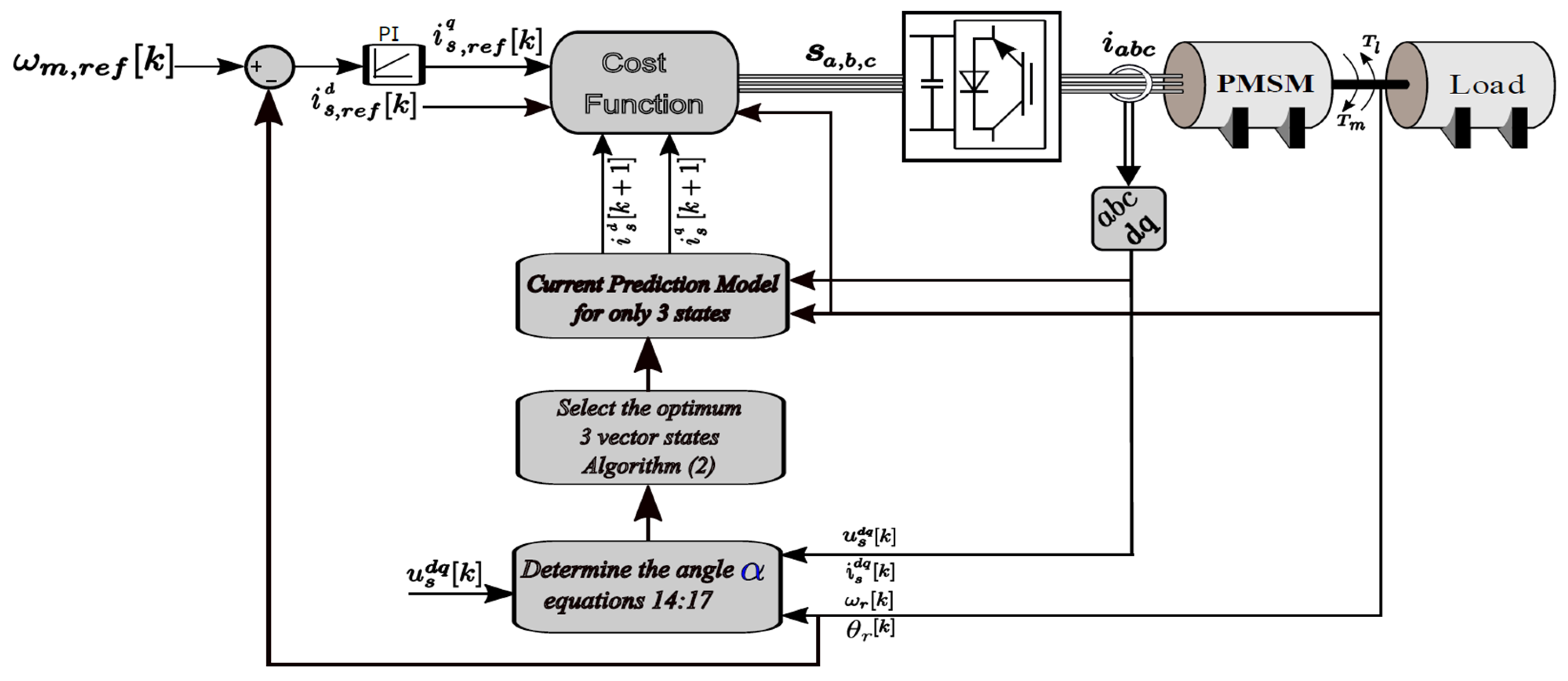
| a. | Calculate , then , then α(k) via Equations (14)–(17). | [executed once] |
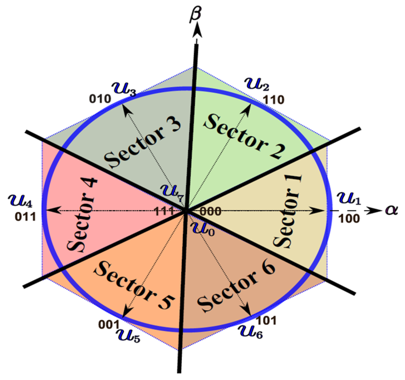
| b. | Identify the sector (via if condition or equivalent equation) | [executed once] |
| c. | Calculate the voltage vector in the dq-frame via Equations (8) and (9). | [executed for three voltage vectors] |
| d. | Calculate the predicted currents in the dq-frame via Equations (11) and (12). | [executed for three voltage vectors] |
| e. | Calculates the cost function using Equation (13). | [executed for three voltage vectors] |
| Algorithm 2: Algorithm of the conventional MPCII |
| Step 1: Read . Step 2: Calculate the required inverter voltage using Equations (14) and (15). Step 3: Calculate the voltage in αβ stationary frame using Equation (16). Step 4: Determine the angle of this voltage using Equation (17). Step 5: Determine sector from α(k) based on Table 2. Step 6: Calculate the voltage vectors for the 3 candidate vectors in the dq-reference frame using Equations (8) and (9). Step 7: Calculate predicted currents for the 3 candidate vectors using Equations (11) and (12). Step 8: Compute the cost function for the candidate vectors using Equation (13), which typically evaluates the error between the predicted currents and reference currents. Step 9: Select the switching state that results in the minimum cost function value. |
4. Proposed Algorithms for Control PMSM
4.1. Proposed MPCI—Two-State Evaluation
| a. | Calculate , then , then α(k) via Equations (14)–(17). | [executed once] |
| b. | Identify the sector (via if condition or equivalent equation) | [executed once] |
| c. | Calculate the voltage vector in the dq-frame via Equations (8) and (9). | [executed for 2 voltage vectors] |
| d. | Calculate the predicted currents in the dq-frame via Equations (11) and (12). | [executed for 2 voltage vectors] |
| e. | Calculate the cost function using Equation (13). | [executed for 2 voltage vectors] |
| Algorithm 3: Algorithm of the proposed MPCI |
| Step 1: Read . Step 2: Calculate the required inverter voltage using Equations (14) and (15). Step 3: Calculate the voltage in αβ stationary frame using Equation (16). Step 4: Determine the angel of this voltage using Equation (17). Step 5: Determine the sector from α(k) based on Table 3. Step 6: Calculate the voltage vectors for the two candidate vectors in the dq-reference frame using Equations (8) and (9). Step 7: Calculate predicted currents for the two candidate vectors using Equations (11) and (12). Step 8: Compute the cost function for the candidate vectors using Equation (13), which typically evaluates the error between the predicted currents and reference currents. Step 9: Select the switching state that results in the minimum cost function value. |
4.2. Proposed MPCII—Direct Evaluation
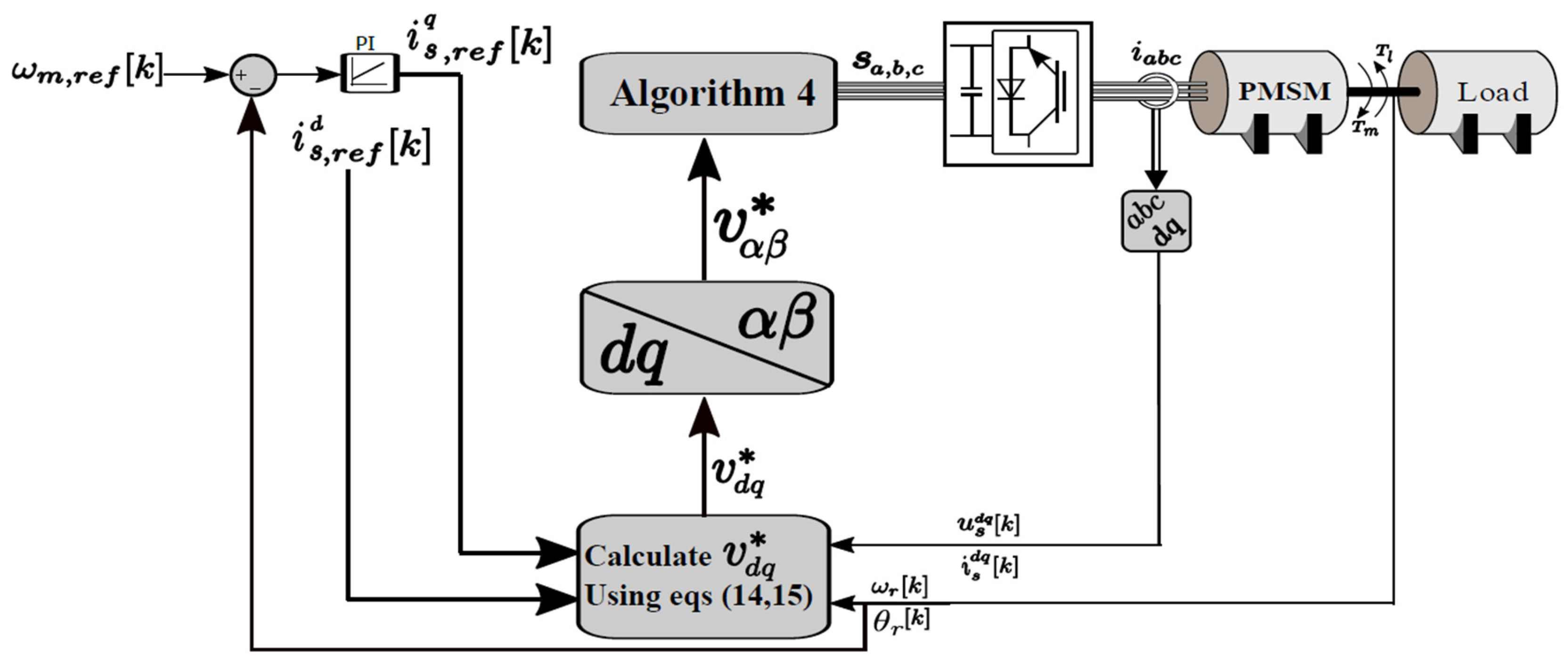
| Algorithm 4: Algorithm of the Proposed MPCII |
| Step 1: Read Step 2: Calculate the required inverter voltage using Equations (14) and (15). Step 3: Calculate the voltage in αβ stationary frame using Equation (16). Step 4: Determine whether is inside the central hexagon using the geometric inclusion check (e.g., inpolygon in MATLAB) If inpolygon = 1 Return the zero-vector state as the optimal switching state. else Determine the angle of the voltage using Equation (17). Based on the value of α(k), determine the optimal switching state according to the following angle intervals: end |
| a. | Calculate then via Equations (14)–(16). | [executed once] |
| b. | Determine whether inside the hexagon. | [executed once] |
| c. | Use a conditional statement (or equivalent expression) to determine inclusion. | [executed once] |
| d. | If it lies outside the hexagon, compute the angle α(k) using Equation (17). | [conditionally executed] |
| e. | Obtain the region and optimal state via conditional logic or an expression. | [conditionally executed] |
5. The Differences Between the Algorithms
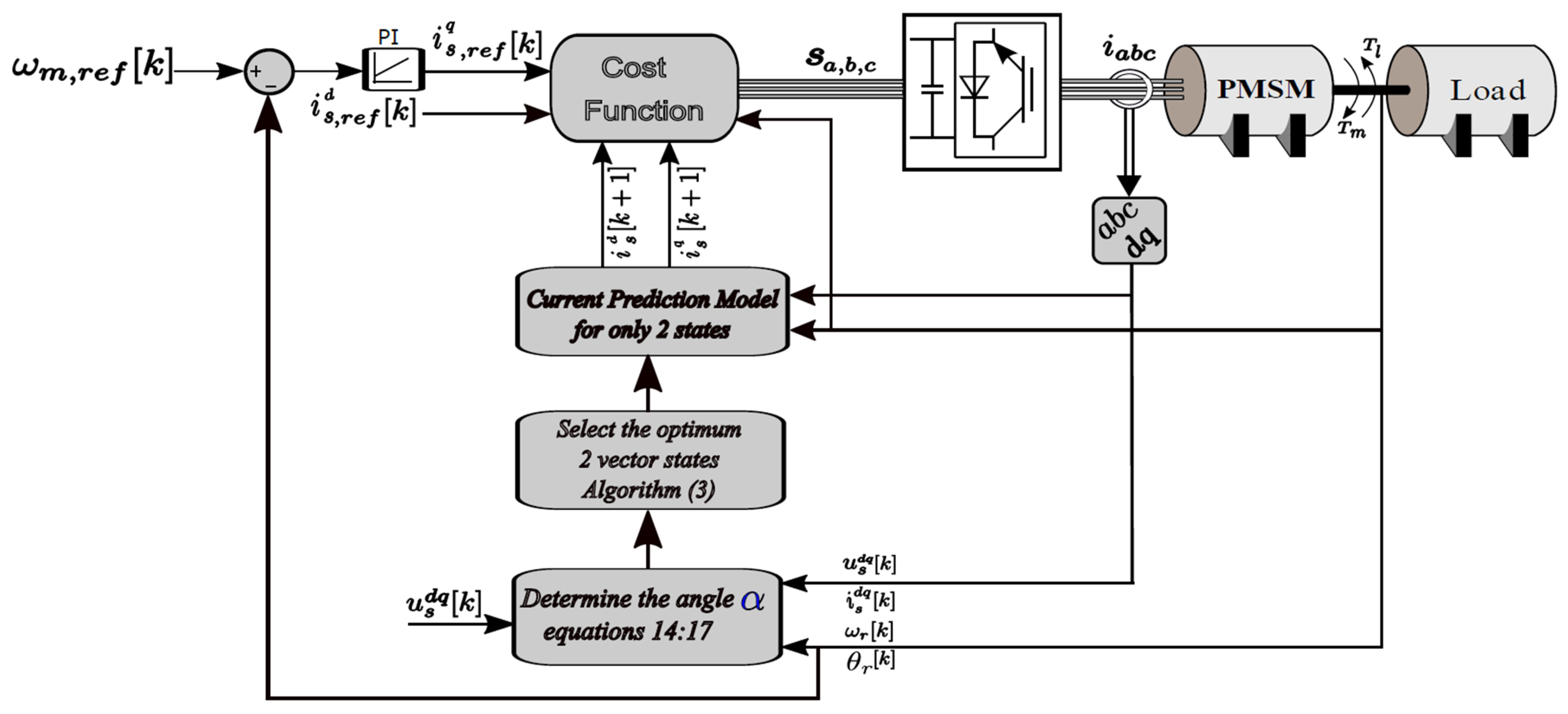
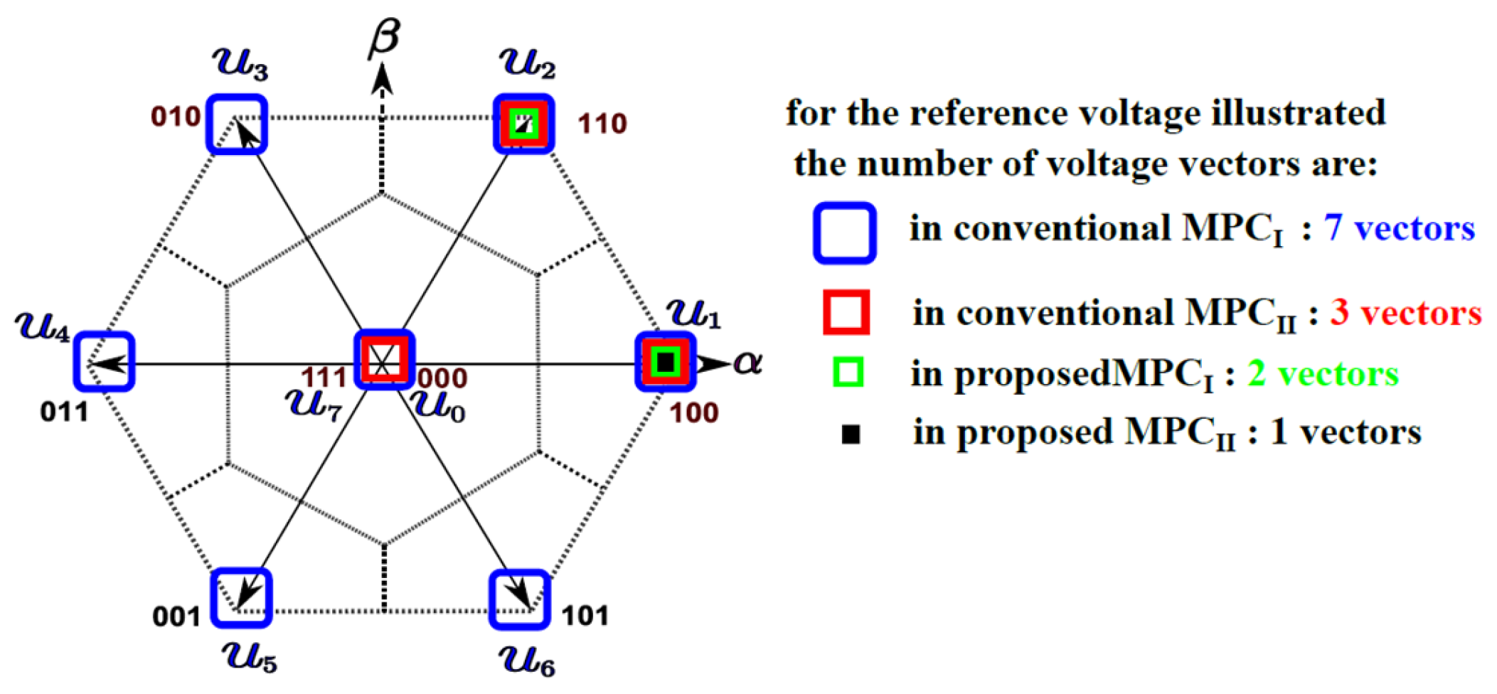
- Conventional MPCI (Algorithm 1): This algorithm evaluates every potential switching state (seven for a two-level inverter), which makes real-time implementation difficult due to its large computing burden (~35 equations each period).
- Conventional MPCII (Algorithm 2): This algorithm improves efficiency while preserving high accuracy by choosing three candidate vectors based on sector identification (around 20 equations each period).
- Proposed MPCI (Algorithm 3): By redefining sectors (around 15 equations each period), it further restricts assessments to two candidate vectors, improving computing efficiency.
- The most efficient method for real-time systems is the proposed MPCII (Algorithm 4), which reduces calculations to 5–7 equations per period by using a geometric integration test to either directly choose the zero state or identify an optimal state depending on the angle.
6. Results and Discussion
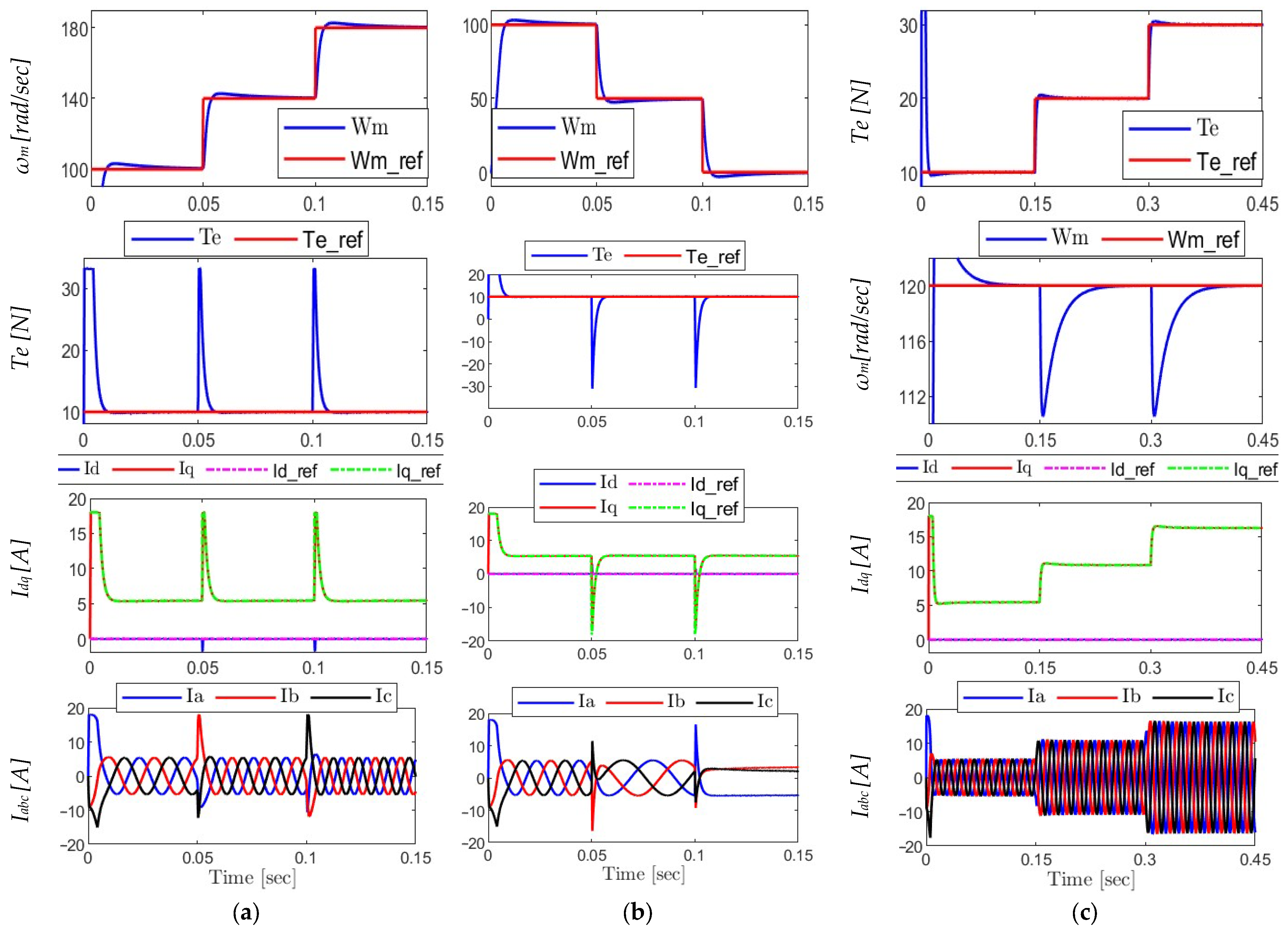
- (a)
- Analysis of the proposed MPCI algorithm under various operating conditions.
- (b)
- Analysis of the proposed MPCII algorithm under various operating conditions.
- (c)
- Comparative analysis between the proposed and conventional approaches.
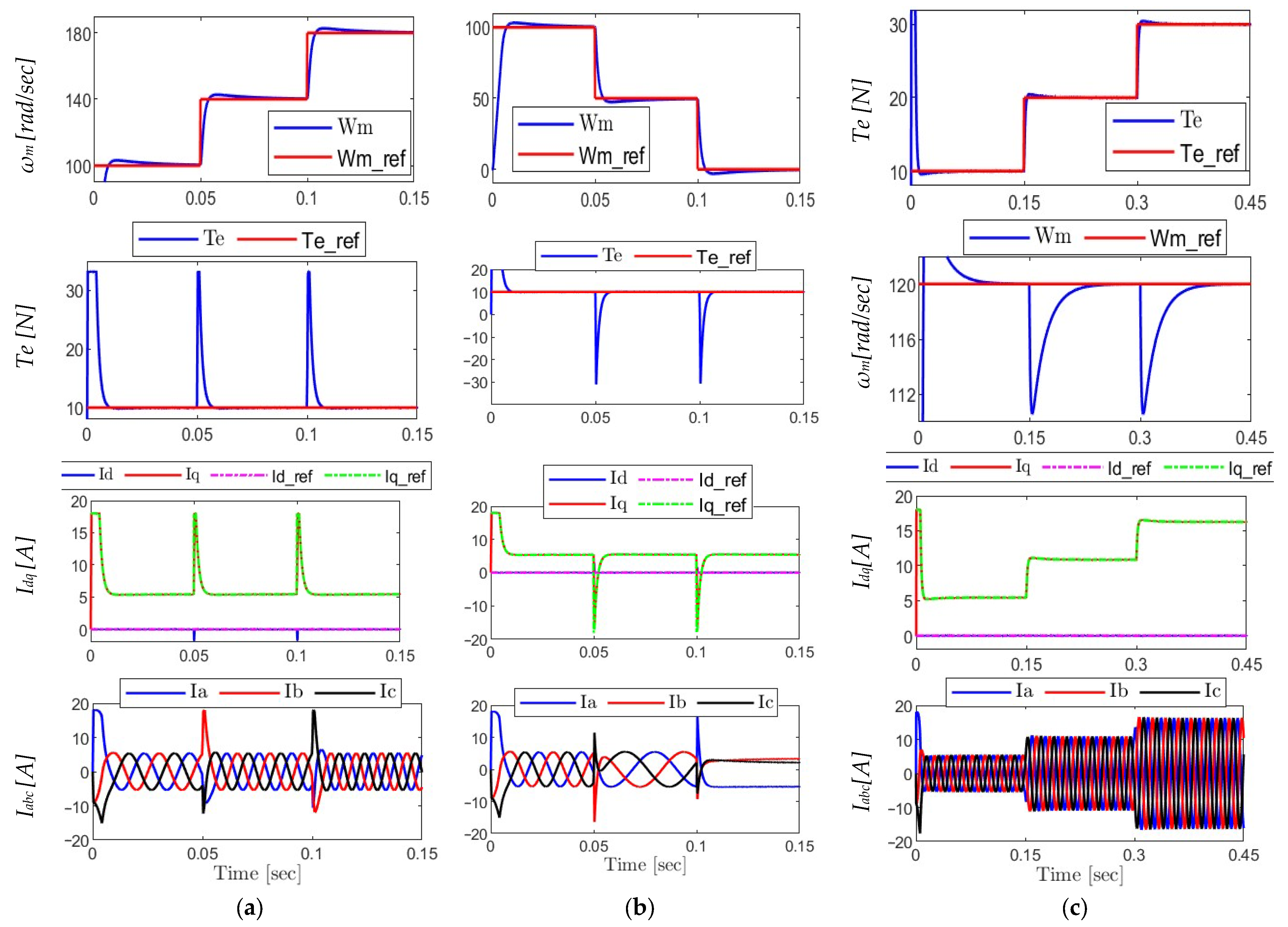
6.1. Analysis of the Proposed MPCI Algorithm Under Various Operating Conditions
- (a)
- Step-Up in Speed
- The speed reference is raised by two steps for the motor.
- There are minor overshoot and steady-state errors, demonstrating fast dynamic behavior, as actual rotor speed ωm rapidly follows the reference ωm,ref.
- The electromagnetic torque Te sudden transition in reaction to changes in speed demonstrates the responsiveness of the control system.
- The d-axis current id is roughly equal to zero, demonstrating adequate PMSM operation, whereas the q-axis current iq precisely matches the torque profile.
- The sinusoidal and balanced ia, ib, and ic stator currents show proper inverter switching.
- (b)
- Speed Step-Down to Standstill
- To simulate slowing down to a stop, the speed reference is gradually reduced until it reaches zero.
- Throughout all phases, the rotor speed ωm keeps tracking the reference precisely and smoothly.
- During braking, there occurs a momentary reversal in torque Te, which is accurately reflected in the iq waveform.
- The id component stays close to zero, guaranteeing appropriate flux direction.
- The stator currents maintain their balance and sinusoidal during transitional phases, confirming stability during deceleration.
- (c)
- Torque Variation at Constant Speed
- The torque reference Te,ref is changed in three separate phases while keeping the speed constant.
- Each torque adjustment is followed by a quick and steady reaction in Te with little settling time
- There is no change in the rotor speed ωm, indicating resilience and efficient decoupling.
- While id is relatively constant, the torque change is accurately reflected by the iq current.
- Although the waveforms maintain their sinusoidal shape, the amplitude of stator currents varies with torque levels.
- Overall, the findings show that under a variety of operating situations, the first proposed MPC algorithm provides high dynamic stability, precise torque and speed tracking, and outstanding current quality.
6.2. Analysis of the Proposed MPCII Algorithm Under Various Operating Conditions
- The rotor speed closely matches its reference
- When the load varies, the electromagnetic torque reacts rapidly.
- The three-phase stator currents stay balanced and sinusoidal during all transitions.
- The dq-axis currents preserve predicted profiles, with id staying near zero and iq exactly matching torque demands.
6.3. Comparative Analysis Between the Proposed and Conventional Approaches
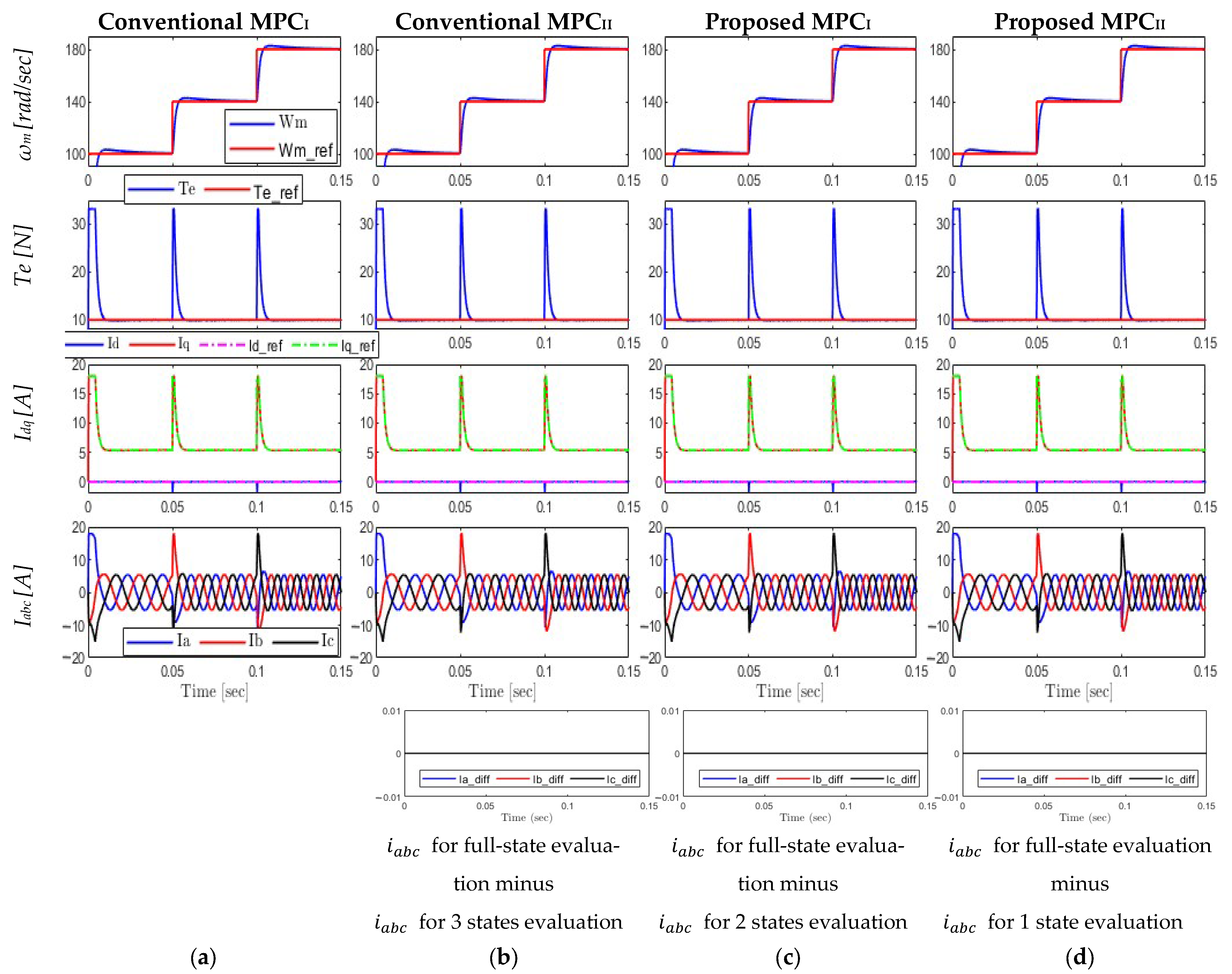
6.3.1. Step Increase in Reference Speed
- Rotor Speed (ωm) and Torque (Te): All controllers exhibit efficient speed control by precisely tracking the reference speed and torque with little overshoot and quick reaction.
- dq Currents (id, iq): All controllers exhibit well-regulated current actions that have a relationship with torque demand.
- Three-Phase Currents (iabc): The sinusoidal and balanced waveforms show that the inverter is operating and regulating current properly.
- The speed tracking root mean square error (RMSE) was identical for all algorithms; its value was 6.37 for the entire simulation period.
- The d- and q-axis current tracking errors (RMSEs) were the same among the algorithms; the values were 0.086 and 0.706, respectively, for the full simulation time.
- The torque ripple was calculated during the steady-state period (0.065–0.1 s); it was the same for all algorithms, with 3.72%.
- Current Difference (Row 5): Although certain approaches use fewer states, differences between full-state and reduced-state (one-, two-, and three-state) assessments are none, demonstrating that all algorithms provide the same three-phase current outputs. Consequently, the total harmonic distortion (THD) is also the same for all of them validating the reduced-complexity model.
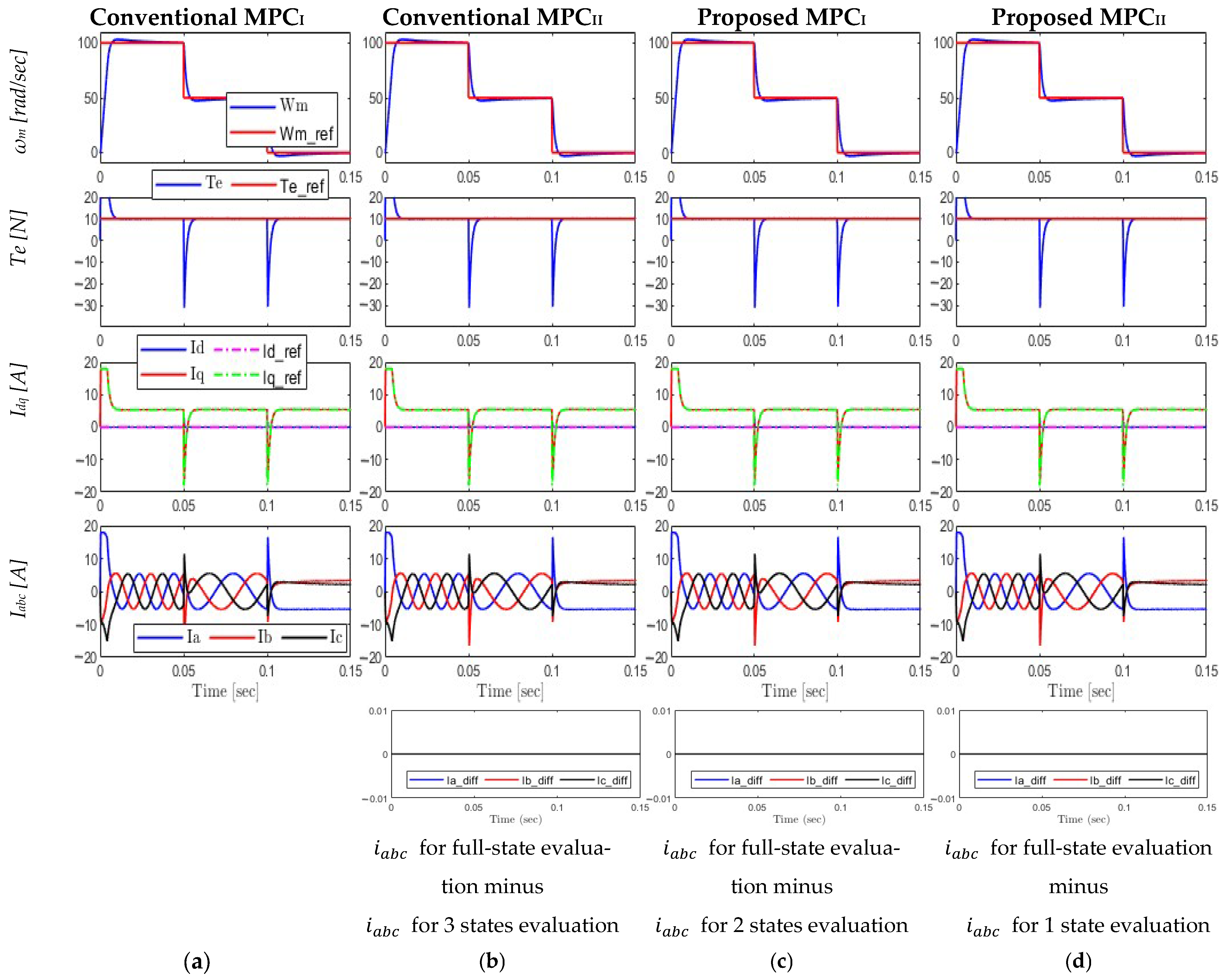
6.3.2. Step Decrease in Reference Speed
- Rotor Speed and Torque: All controllers once more demonstrate accurate tracking, rapid deceleration, and steady transitions, demonstrating resilience in decelerating circumstances.
- Currents: With equally clear and steady profiles, the dq and abc currents behave similarly to the previous case.
- Speed tracking (RMSE) for all algorithms was equal to 6.68 for full interval.
- The d- and q-axis current (RMSE) were again identical for algorithms. It is measured at 0.112 and 1.081, respectively.
- The torque ripple is evaluated in the steady-state region (0.065–0.1 s) and it was uniform for the algorithms, with a value of 3.74%.
- Current Difference: Once more, the current difference graphs (bottom row) demonstrate the computational effectiveness of the reduced-state algorithms without compromising performance, which means that the total harmonic distortion (THD) is identical for all methods, confirming that all reduced-state assessments match the full-state findings.
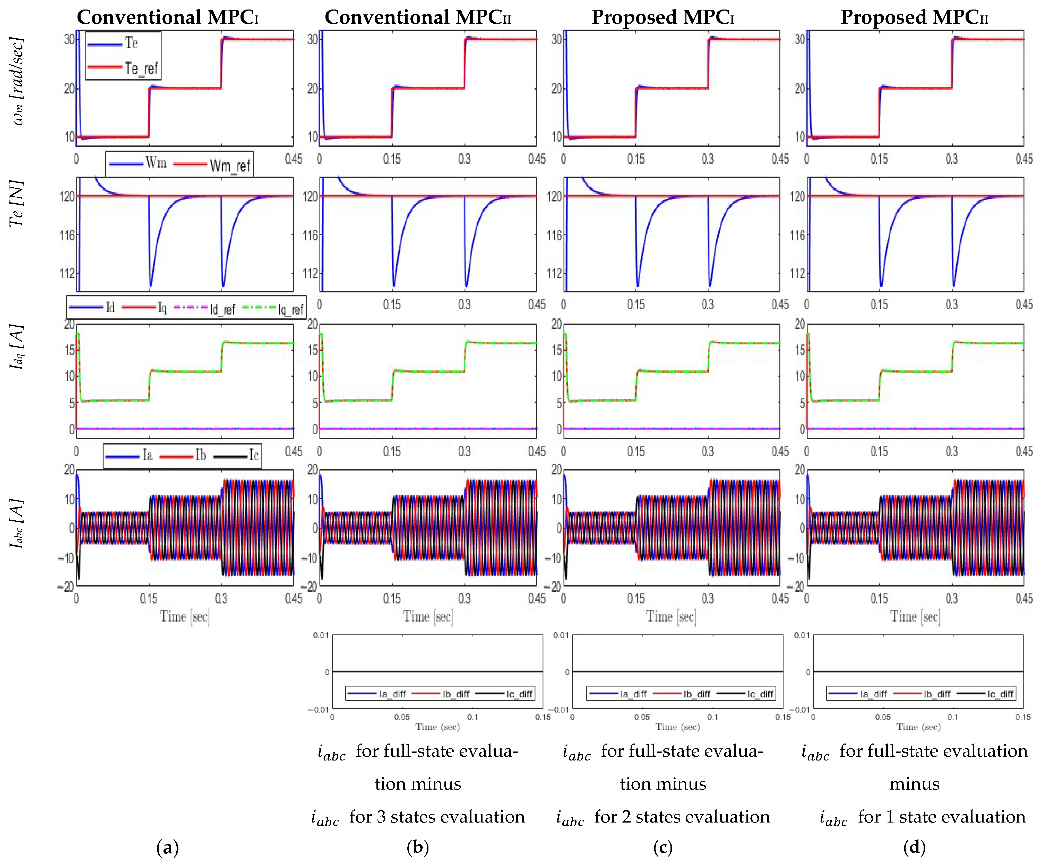
6.3.3. Torque Variation at Constant Speed
- Speed and Torque: The controllers exhibit decoupling control efficacy by maintaining a steady speed even when torque steps are applied. The torque response stays precise and follows the standard.
- Currents: abc currents maintain high-quality waveforms, but dq currents adapt suitably to torque demands.
- The speed tracking (RMSE) was again uniform for all algorithms; it was 5.019.
- The d- and q-axis current tracking errors were consistent also for algorithms, with values of 0.112 and 0.289, respectively, for the full interval.
- The torque ripple is calculated for the steady-state period (0.2–0.3 s); it was the same for all algorithms, with a value of 1.73%.
- Current Difference: Even under different torque settings, the suggested reduced-state algorithms operate exactly like the full-state one indicating that (THD) is also the same.
6.3.4. Comparing the Computational Time
- Conventional MPCI: 1.867 s → (baseline)
- Conventional MPCII: 1.593 s → 14.68% improvement
- Proposed MPCI: 1.417 s → 24.10% improvement
- Proposed MPCII: 1.127 s → 39.64% improvement
7. Conclusions
Author Contributions
Funding
Data Availability Statement
Conflicts of Interest
References
- Adel, M.M.; Ahmed, W.A.; Taha, M.; Saleh, A.A. Enhanced Sensorless Field Oriented Controlled PMSM Drive Using Fractional Calculus and PSO Technique. In Proceedings of the 2020 International Symposium on Power Electronics, Electrical Drives, Automation and Motion (SPEEDAM), Sorrento, Italy, 24–26 June 2020; pp. 5–10. [Google Scholar] [CrossRef]
- El Maguid Ahmed, W.A.; Adel, M.M.; Taha, M.; Saleh, A.A. PSO technique applied to sensorless field-oriented control PMSM drive with discretized RL-fractional integral. Alex. Eng. J. 2021, 60, 4029–4040. [Google Scholar] [CrossRef]
- FPGA-Based High Performance Sensorless Control for PMSM Drives (Berichte aus der Elektrotechnik)—Ma, Zhixun: 9783844028553—AbeBooks. Available online: https://www.abebooks.com/9783844028553/FPGA-Based-High-Performance-Sensorless-Control-3844028552/plp (accessed on 5 September 2025).
- Maji, P.; Kpanda, G.; Ksaha, P. Field oriented control of permanent magnet synchronous motor using PID controller. Adv. Res. Electr. Electron. Instrum. Eng. 2015, 4, 632–639. [Google Scholar]
- Tawfiq, K.B.; Mansour, A.S.; Sergeant, P. Mathematical Design and Analysis of Three-Phase Inverters: Different Wide Bandgap Semiconductor Technologies and DC-Link Capacitor Selection. Mathematics 2023, 11, 2137. [Google Scholar] [CrossRef]
- Zhang, Y.; Zhu, J. Direct Torque Control of Permanent Magnet Synchronous Motor with Reduced Torque Ripple and Commutation Frequency. IEEE Trans. Power Electron. 2011, 26, 235–248. [Google Scholar] [CrossRef]
- Lin, X.; Huang, W.; Jiang, W.; Zhao, Y.; Zhu, S. A Stator Flux Observer With Phase Self-Tuning for Direct Torque Control of Permanent Magnet Synchronous Motor. IEEE Trans. Power Electron. 2020, 35, 6140–6152. [Google Scholar] [CrossRef]
- Foo, G.H.B.; Zhang, X. Constant Switching Frequency Based Direct Torque Control of Interior Permanent Magnet Synchronous Motors With Reduced Ripples and Fast Torque Dynamics. IEEE Trans. Power Electron. 2016, 31, 6485–6493. [Google Scholar] [CrossRef]
- Farhan, A.; Abdelrahem, M.; Saleh, A.; Shaltout, A.; Kennel, R. Simplified Sensorless Current Predictive Control of Synchronous Reluctance Motor Using Online Parameter Estimation. Energies 2020, 13, 492. [Google Scholar] [CrossRef]
- Trubenbach, R.A.; Mackay, A.T.; Kamper, M.J. Performance of a reluctance synchronous machine under vector control. In Proceedings of the IEEE Power Electronics Specialist Conference—PESC ’93, Seattle, WA, USA, 20–24 June 1993; pp. 803–808. [Google Scholar] [CrossRef]
- Siami, M.; Khaburi, D.A.; Rodriguez, J. Simplified finite control set-model predictive control for matrix converter-fed PMSM drives. IEEE Trans. Power Electron. 2017, 33, 2438–2446. [Google Scholar] [CrossRef]
- Abdelrahem, M.; Hackl, C.M.; Kahia, B.; Kennel, R. Predictive Direct Torque Control Strategy for Surface-Mounted Permanent-Magnet Synchronous Generators. In Proceedings of the NEIS 2017; Conference on Sustainable Energy Supply and Energy Storage Systems, Hamburg, Germany, 21–22 September 2017; pp. 1–6. Available online: https://ieeexplore.ieee.org/document/8421831 (accessed on 6 September 2025).
- Geyer, T.; Quevedo, D.E. Multistep finite control set model predictive control for power electronics. IEEE Trans. Power Electron. 2014, 29, 6836–6846. [Google Scholar] [CrossRef]
- Zafra, E.; Vazquez, S.; Geyer, T.; Aguilera, R.P.; Freire, E.; Franquelo, L.G. Computational analysis of the long horizon FCS-MPC problem for power converters. IEEE Trans. Power Electron. 2024, 39, 12762–12773. [Google Scholar] [CrossRef]
- Iqbal, A.; Abu-Rub, H.; Ahmed, S.K.M.; Cortes, P.; Rodriguez, J. Model predictive current control of a three-level five-phase NPC VSI using simplified computational approach. In Proceedings of the 2014 IEEE Applied Power Electronics Conference and Exposition—APEC 2014, Fort Worth, TX, USA, 16–20 March 2014; pp. 2323–2330. [Google Scholar]
- Hu, J.; Zhu, J.; Lei, G.; Platt, G.; Dorrell, D.G. Multi-objective model-predictive control for high-power converters. IEEE Trans. Energy Convers. 2013, 28, 652–663. [Google Scholar]
- Cortés, P.; Wilson, A.; Kouro, S.; Rodriguez, J.; Abu-Rub, H. Model predictive control of multilevel cascaded H-bridge inverters. IEEE Trans. Ind. Electron. 2010, 57, 2691–2699. [Google Scholar] [CrossRef]
- Habibullah, M.; Lu, D.D.-C.; Xiao, D.; Rahman, M.F. A simplified finite-state predictive direct torque control for induction motor drive. IEEE Trans. Ind. Electron. 2016, 63, 3964–3975. [Google Scholar] [CrossRef]
- Siami, M.; Khaburi, D.A.; Rivera, M.; Rodriguez, J. A computationally efficient lookup table based FCS-MPC for PMSM drives fed by matrix converters. IEEE Trans. Ind. Electron. 2017, 64, 7645–7654. [Google Scholar] [CrossRef]
- Mohsen, S.; Amiri, M.; Savadkoohi, H.K.; Rezavandi, R.; Valipour, S. Simplified predictive torque control for a PMSM drive fed by a matrix converter with imposed input current. IEEE J. Emerg. Sel. Top. Power Electron. 2018, 6, 1641–1649. [Google Scholar] [CrossRef]
- Zhang, Y.; Xie, W.; Li, Z.; Zhang, Y. Low-complexity model predictive power control: Double-vector-based approach. IEEE Trans. Ind. Electron. 2014, 61, 5871–5880. [Google Scholar] [CrossRef]
- Ji, D.; Ren, J.; Liu, C.; Shi, Y. Stabilizing terminal constraint-free nonlinear MPC via sliding mode-based terminal cost. Automatica 2021, 134, 109898. [Google Scholar] [CrossRef]
- Hadla, H.; Cruz, S. Predictive Stator Flux and Load Angle Control of Synchronous Reluctance Motor Drives Operating in a Wide Speed Range. IEEE Trans. Ind. Electron. 2017, 64, 6950–6959. [Google Scholar] [CrossRef]
- Zhang, X.; Foo, G.H.B.; Vilathgamuwa, D.M.; Maskell, D.L. An Improved Robust Field-Weakeaning Algorithm for Direct-Torque-Controlled Synchronous-Reluctance-Motor Drives. IEEE Trans. Ind. Electron. 2015, 62, 3255–3264. [Google Scholar] [CrossRef]
- Tang, L.; Zhong, L.; Rahman, M.F.; Hu, Y. A novel direct torque controlled interior permanent magnet synchronous machine drive with low ripple in flux and torque and fixed switching frequency. IEEE Trans. Power Electron. 2004, 19, 346–354. [Google Scholar] [CrossRef]
- Xia, C.; Wang, Y.; Shi, T. Implementation of Finite-State Model Predictive Control for Commutation Torque Ripple Minimization of Permanent-Magnet Brushless DC Motor. IEEE Trans. Ind. Electron. 2013, 60, 896–905. [Google Scholar] [CrossRef]
- Carlet, P.G.; Tinazzi, F.; Bolognani, S.; Zigliotto, M. An Effective Model-Free Predictive Current Control for Synchronous Reluctance Motor Drives. IEEE Trans. Ind. Appl. 2019, 55, 3781–3790. [Google Scholar] [CrossRef]
- Abdelrahem, M.; Hackl, C.; Kennel, R. Simplified model predictive current control without mechanical sensors for variable-speed wind energy conversion systems. Electr. Eng. 2017, 99, 367–377. [Google Scholar] [CrossRef]
- Farhan, A.; Saleh, A.; Shaltout, A. High performance Reluctance Synchronous Motor drive using Field Oriented Control. In Proceedings of the 2013 5th International Conference on Modelling, Identification and Control (ICMIC), Cairo, Egypt, 31 August–2 September 2013; pp. 181–186. Available online: https://ieeexplore.ieee.org/document/6642215 (accessed on 6 September 2025).
- Consoli, A.; Russo, F.; Scarcella, G.; Testa, A. Low and zero speed sensorless control of synchronous reluctance motors. In Proceedings of the Conference Record of 1998 IEEE Industry Applications Conference. Thirty-Third IAS Annual Meeting (Cat. No.98CH36242), St. Louis, MO, USA, 12–15 October 1998; Volume 1, pp. 685–692. [Google Scholar] [CrossRef]
- Zhang, Y.; Lin, H. Simplified model predictive current control method of voltage-source inverter. In Proceedings of the 8th International Conference on Power Electronics—ECCE Asia, Jeju, Republic of Korea, 30 May–3 June 2011; pp. 1726–1733. [Google Scholar] [CrossRef]
- Kouro, S.; Cortes, P.; Vargas, R.; Ammann, U.; Rodriguez, J. Model Predictive Control—A Simple and Powerful Method to Control Power Converters. IEEE Trans. Ind. Electron. 2009, 56, 1826–1838. [Google Scholar] [CrossRef]
- Hong, J.; Pan, D.; Zong, Z. Comparison of the Two Current Predictive-Control Methods for a Segment-Winding Permanent-Magnet Linear Synchronous Motor. IEEE Trans. Plasma Sci. 2013, 41, 1167–1173. [Google Scholar] [CrossRef]
- Gao, X.; Abdelrahem, M.; Hackl, C.M.; Zhang, Z.; Kennel, R. Direct Predictive Speed Control With a Sliding Manifold Term for PMSM Drives. IEEE J. Emerg. Sel. Top. Power Electron. 2020, 8, 1258–1267. [Google Scholar] [CrossRef]
- Filho, C.J.V.; Xiao, D.; Vieira, R.P.; Emadi, A. Observers for High-Speed Sensorless PMSM Drives: Design Methods, Tuning Challenges and Future Trends. IEEE Access 2021, 9, 56397–56415. [Google Scholar] [CrossRef]
- Hassan, M.A.; Adel, M.M.; Farhan, A.; Saleh, A.A. Finite speed-set model reference adaptive system based on sensorless control of permanent magnet synchronous generators for wind turbines. Machines 2024, 12, 429. [Google Scholar] [CrossRef]
- Farhan, A.; Abdelrahem, M.; Hackl, C.M.; Kennel, R.; Shaltout, A.; Saleh, A. Advanced Strategy of Speed Predictive Control for Nonlinear Synchronous Reluctance Motors. Machines 2020, 8, 44. [Google Scholar] [CrossRef]
- Farhan, A.; Saleh, A.; Abdelrahem, M.; Kennel, R.; Shaltout, A. High-precision sensorless predictive control of salient-pole permanent magnet synchronous motor based-on extended Kalman filter. In Proceedings of the 2019 21st International Middle East Power Systems Conference (MEPCON), Cairo, Egypt, 17–19 December 2019; pp. 226–231. Available online: https://ieeexplore.ieee.org/abstract/document/9008188/ (accessed on 4 May 2025).


| Inverter State | |||||
|---|---|---|---|---|---|
| 0 | 000 | 111 | 0 | 0 | 0 |
| 1 | 100 | 011 | 2/3 | −1/3 | −1/3 |
| 2 | 110 | 001 | 1/3 | 1/3 | −2/3 |
| 3 | 010 | 101 | −1/3 | 2/3 | −1/3 |
| 4 | 011 | 100 | −2/3 | 1/3 | 1/3 |
| 5 | 001 | 110 | −1/3 | −1/3 | 2/3 |
| 6 | 101 | 010 | 1/3 | −2/3 | 1/3 |
| 7 | 111 | 000 | 0 | 0 | 0 |
| Angle Range | Sector | Candidate Vectors |
|---|---|---|
| 1 | 0, 1, 2 | |
| 2 | 0, 2, 3 | |
| 3 | 0, 3, 4 | |
| 4 | 0, 4, 5 | |
| 5 | 0, 5, 6 | |
| 6 | 0, 6, 1 |
| Angle Range | Sector | Candidate Vectors |
|---|---|---|
| 1 | 0, 1 | |
| 2 | 0, 2 | |
| 3 | 0, 3 | |
| 4 | 0, 4 | |
| 5 | 0, 5 | |
| 6 | 0, 6 |
| Selection Criteria | Region | Optimal Vectors (State) | |
|---|---|---|---|
| Inside the middle hexagon | - | 0 | 0 |
| Outside the middle hexagon | 1 | 1 | |
| Outside the middle hexagon | 2 | 2 | |
| Outside the middle hexagon | 3 | 3 | |
| Outside the middle hexagon | 4 | 4 | |
| Outside the middle hexagon | 5 | 5 | |
| Outside the middle hexagon | 6 | 6 | |
| Feature | Convention MPCI Algorithm 1 | Convention MPCII Algorithm 2 | Proposed MPCI Algorithm 3 | Proposed MPCII Algorithm 4 |
|---|---|---|---|---|
| Full Vector Evaluation | yes | no | no | no |
| Number of candidates vectors | Increase exponentially | constant | constant | constant |
| for 2-level inverter | 7 | 3 | 2 | 1 |
| for 3-level inverter | 19 | 3 | 2 | 1 |
| for 5-level inverter | 61 | 3 | 2 | 1 |
| Calculation of vector voltages in dq, predicted currents and the cost function | yes | yes | yes | no |
| Calculation of angle of the reference voltage | no | yes | yes | conditionally |
| Conditional logic | No | yes | yes | yes |
| Approximated number of equations per cycle | Increase exponentially | Constant | constant | constant |
| for 2-level inverter | 5 × 7 = 35 | 20 | 15 | 5–7 |
| for 3-level inverter | 5 × 19 = 95 | 20 | 15 | 5–7 |
| for 5-level inverter | 5 × 61 = 305 | 20 | 15 | 5–7 |
| Parameter | Nomenclature/Unit | Value |
|---|---|---|
| flux linkage | 0.41 | |
| Nominal d-axis inductance | Ld [H] | 0.01 |
| Nominal q-axis inductance | Lq [H] | 0.01 |
| Nominal Stator resistance | Rs [Ω] | 1.3 |
| Number of Pole pairs | P | 3 |
| Rotor inertia | J [kg.m2] | 0.0012 |
Disclaimer/Publisher’s Note: The statements, opinions and data contained in all publications are solely those of the individual author(s) and contributor(s) and not of MDPI and/or the editor(s). MDPI and/or the editor(s) disclaim responsibility for any injury to people or property resulting from any ideas, methods, instructions or products referred to in the content. |
© 2025 by the authors. Licensee MDPI, Basel, Switzerland. This article is an open access article distributed under the terms and conditions of the Creative Commons Attribution (CC BY) license (https://creativecommons.org/licenses/by/4.0/).
Share and Cite
Salah, M.; Tawfiq, K.B.; Mansour, A.S.; Farhan, A. Novel Model Predictive Control Strategies for PMSM Drives: Reducing Computational Burden and Enhancing Real-Time Implementation. Machines 2025, 13, 908. https://doi.org/10.3390/machines13100908
Salah M, Tawfiq KB, Mansour AS, Farhan A. Novel Model Predictive Control Strategies for PMSM Drives: Reducing Computational Burden and Enhancing Real-Time Implementation. Machines. 2025; 13(10):908. https://doi.org/10.3390/machines13100908
Chicago/Turabian StyleSalah, Mohamed, Kotb B. Tawfiq, Arafa S. Mansour, and Ahmed Farhan. 2025. "Novel Model Predictive Control Strategies for PMSM Drives: Reducing Computational Burden and Enhancing Real-Time Implementation" Machines 13, no. 10: 908. https://doi.org/10.3390/machines13100908
APA StyleSalah, M., Tawfiq, K. B., Mansour, A. S., & Farhan, A. (2025). Novel Model Predictive Control Strategies for PMSM Drives: Reducing Computational Burden and Enhancing Real-Time Implementation. Machines, 13(10), 908. https://doi.org/10.3390/machines13100908


