Article

Metamodel-Based Digital Twin Architecture with ROS Integration for Heterogeneous Model Unification in Robot Shaping Processes

1
State Key Laboratory of Robotics, Shenyang Institute of Automation, Chinese Academy of Sciences, Shenyang 110169, China
2
University of the Chinese Academy of Sciences, Beijing 101408, China
*
Author to whom correspondence should be addressed.
Machines 2025, 13(10), 898; https://doi.org/10.3390/machines13100898
Submission received: 22 August 2025 / Revised: 15 September 2025 / Accepted: 19 September 2025 / Published: 1 October 2025
(This article belongs to the Section Advanced Manufacturing)

Abstract

Precision manufacturing requires handling multi-physics coupling during processing, where digital twin and AI technologies enable rapid robot programming under customized requirements. However, heterogeneous data sources, diverse domain models, and rapidly changing demands pose significant challenges to digital twin system integration. To overcome these limitations, this paper proposes a digital twin modeling strategy based on a metamodel and a virtual–real fusion architecture, which unifies models between the virtual and physical domains. Within this framework, subsystems achieve rapid integration through ontology-driven knowledge configuration, while ROS provides the execution environment for establishing robot manufacturing digital twin scenarios. A case study of a robot shaping system demonstrates that the proposed architecture effectively addresses heterogeneous data association, model interaction, and application customization, thereby enhancing the adaptability and intelligence of precision manufacturing processes.

1. Introduction

Robots are increasingly applied in industrial production due to advances in science, technology, and artificial intelligence [1]. In precision machining, conventional machine tools are often limited by workpiece size and accessibility, whereas robots can perform complex three-dimensional operations with high flexibility, automation, accuracy, safety, and cost efficiency, making them a promising alternative to traditional methods [2,3].
A central challenge in robotic manufacturing is achieving customized production without compromising precision. Robot precision manufacturing is a machining process involving multiphysical field coupling. The cutting force, for example, can cause tool and workpiece deformation, leading to machining errors [4]. The complexity of these interactions is evident in other advanced manufacturing processes like electrochemical machining, where material removal is governed by the interplay of fluid dynamics, electric fields, and mass transfer of multiple ion species [5]. Effectively modeling such systems often requires a hybrid approach, combining detailed physics-based simulations with data-driven methods that can provide real-time predictions [6,7] without the full computational cost of first-principles models.
Therefore, before actual processing, it is necessary to integrate digital twin and AI technologies to create a transparent, virtual–real fusion simulation environment. This environment can simulate temperature [8], pressure [9], and elasticity [10] during workpiece processing, providing an adequate training set to correct errors caused by these coupled factors and enabling rapid robot programming for custom requirements [11]. This approach enhances decision-making and reliability in robotic operations.
Digital twins, first proposed by Grieves and initially applied in aerospace [12], have been adopted in manufacturing for equipment monitoring, virtual debugging, and operational planning [13]. In robotics, most studies focus on dynamic mapping and state monitoring, with limited data utilization. Recent advances include vision-based control integrated with CAD data [14], ROS-based tools for heterogeneous model integration [15], and cognitive twin architectures for ontology-based simulation [16]. Despite these advances, challenges remain in real-time interaction, system scheduling, and seamless virtual–real integration, motivating the development of metamodel-based digital twin strategies to enhance adaptability and precision in robotic manufacturing systems.
In [17], vision-based control for disassembly tasks utilizes CAD and vision data to inform task planning, illustrating how geometric information can be integrated to improve precision and adaptability. The simulation of the robotic operation tasks is implemented in a digital environment. The ROS-based packaging tool developed by Vazirpanah aims to integrate heterogeneous models built in different simulation environments into a unified formal heterogeneous modeling framework [18]. The interaction between models is through topics, but the real-time correlation and scheduling between systems cannot be guaranteed. A cognitive twin architecture is designed to construct different domain models into a unified semantic ontology model and automatically transform them into an FMI model to realize a digital twin simulation of a complex system [19]. Although these cases provide some useful simulation models or architectures, there are still some challenges in the practical application of digital twinning and AI technology [14,20].
There are challenges in heterogeneous data source association and measurement during virtual and real simulations. Generally speaking, the control effect in the virtual simulation scenario is completely dependent on the fully aware virtual sensor, and the data has its own label. In the actual use process, the more complex the system is, the more information it needs to be perceived, and the greater the amount of associated data required. Taking robot cutting as an example, all of the state data of the robot in the simulation process can be known by default, but in the actual production process, the stress sensor, the laser tracker, the temperature sensor, and other sensing equipment are needed. However, there are still some unpredictable data points which the fusion of a variety of sensor information is needed to predict, such as the slow rebound amount of parts, instantaneous cutting force, etc. Because the above data has a direct impact on the system control effect, it is necessary to associate and link various data types, and in different manufacturing conditions, the quantity, type, format, features, and other differences are large, and rapid data integration applications have thus become a great challenge.
Model error poses cross-system integration challenges. There have been many successes for robot applications developed based on model design [21,22,23], enabling designers to iterate and refine the design in a virtual environment before actually deploying a physical robot. However, it is difficult for a model used in virtual simulation to accurately reflect the processing changes in real artifacts, especially the processing scene for multiphysical field coupling, and it is difficult for a single model to characterize the complex processing process and state changes. Therefore, in the virtual and real fusion scenario, it is necessary to provide a variety of model correction or system recognition interfaces, but under the existing implementation architecture, realizing model unification between the virtual world and the real world is still an important problem to solve urgently.
The changing customization requirements bring strong scalability challenges to system application integration development. Since each customization requirement may require a different combination of models, different process characteristics require different processing parameters. Robotic application development requires a flexible combination and parameter configuration in the models. For example, the working parameters, the motion planning algorithm, or the control strategy of the robot can be adjusted through configuration files or parameter settings. Configurability enables the system to quickly adapt to changing needs without large-scale development and adjustment. At the same time, by defining a unified interface and communication protocol, different components and devices can be seamlessly integrated. At the application layer, we need to achieve flexible and scalable arrangements from multiple dimensions, such as algorithms, models, and hardware, so that the system can quickly adapt to the changing needs without large-scale development and adjustment.
Therefore, this work proposes a metamodel-driven digital twin modeling strategy with a virtual–real fusion implementation architecture to address the challenges of heterogeneous data, model diversity, and dynamic customization in precision manufacturing. The focus lies in rapidly designing and constructing robot digital twin systems capable of meeting the demands of customized precision machining. The main contributions are summarized as follows:
(1)
We propose a novel digital twin implementation architecture for precision manufacturing that encapsulates both physical and virtual systems, enabling the unified design and programming of a shaping system digital twin within a single environment.
(2)
Building upon this architecture, we develop a metamodel-based digital twin operation mechanism and establish a unified simulation environment through ontology-driven configuration. This approach allows subsystems to achieve rapid integration, while ROS serves as the execution platform for virtual–real fusion, thereby supporting the construction of executable robot manufacturing digital twin scenarios.
The system proposed in this paper establishes a unified model bridging the virtual and physical worlds. By abstracting physical entities and algorithms into agents, it forms a distributed network of nodes that allows designers to independently modify and optimize the system. Consequently, precision manufacturing of the developed robot can dynamically adapt to changing conditions, and the proposed framework significantly enhances the system’s adaptability, flexibility, and consistency.

2. Precision Manufacturing Mode Based on Digital Twins

The existing precision manufacturing mode mainly relies on CNC machine tools or robots for machining, as shown on the left side of Figure 1. The robot only processes based on the trajectory planning results, which is equivalent to an open-loop control process. The present study introduces an innovative framework that systematically bridges physical and virtual domains for robotic milling applications.
The methodology incorporates real-time condition monitoring (acquiring sensor data from the operational process), multimodal sensory integration (synthesizing diverse perceptual inputs), virtual environment simulation (encompassing rigid-body dynamics, digital machining, and multiphysics modeling to simulate thermal, stress, and deformation phenomena), and online adaptive optimization (iteratively refining physical operations through simulation feedback). This comprehensive methodology enables dynamic process optimization, effectively improving robotic milling performance through synergistic integration of physical operations and computational simulations. The approach demonstrates three key innovations: (1) the implementation of bidirectional data mapping between the physical and virtual domains, (2) the development of a unified digital twin modeling system (DTMS) for coupled simulations, and (3) the establishment of an online closed-loop control mechanism for continuous process enhancement.
However, the existing virtual simulation mainly provides the rigid-body simulation environment of the robot’s kinematics and dynamics, supporting object interaction, such as collision, contact points, grasping, etc. However, existing simulation software struggles to characterize material morphological changes in virtual environments for material reduction manufacturing of flexible bodies, a challenge that becomes particularly pronounced when integrating milling simulations into commonly used robot motion simulation platforms such as CoppeliaSim, Bullet, and Gazebo, among others. As the scale of the system equipment increases, the mapping and correlation between data in the virtual world and data in the physical world will grow exponentially. If the physical model is rebuilt in the virtual environment, this will not only cause the repetition of work but also lead to inconsistency between the data of the system model and the simulation model.
Virtual fusion in closed-loop processing mode requires the actual control process and a digital twin model for real-time interaction and optimization. The urgent need for a digital twin implementation framework is due to consistency between the physical world and the virtual world model, while user system design and integration development provide data between the actual interaction and control.

3. Digital Twin Implementation Architecture

3.1. The Overall Architecture

In the traditional development mode, the core of system function integration is to move through the interaction of multiple physical devices at the data, information, control, and other levels so as to debug and optimize system functions and performance. But modifying the initial design may lead to a lot of subsequent debugging work. With the development of digital twin technology, the construction of virtual and real interactive closed-loop systems with models and data as the core has become an important means to realize business optimization. How to accurately digitally map physical objects into the information space and realize a digital twin system with virtual and real fusion has become a key problem to solve urgently.
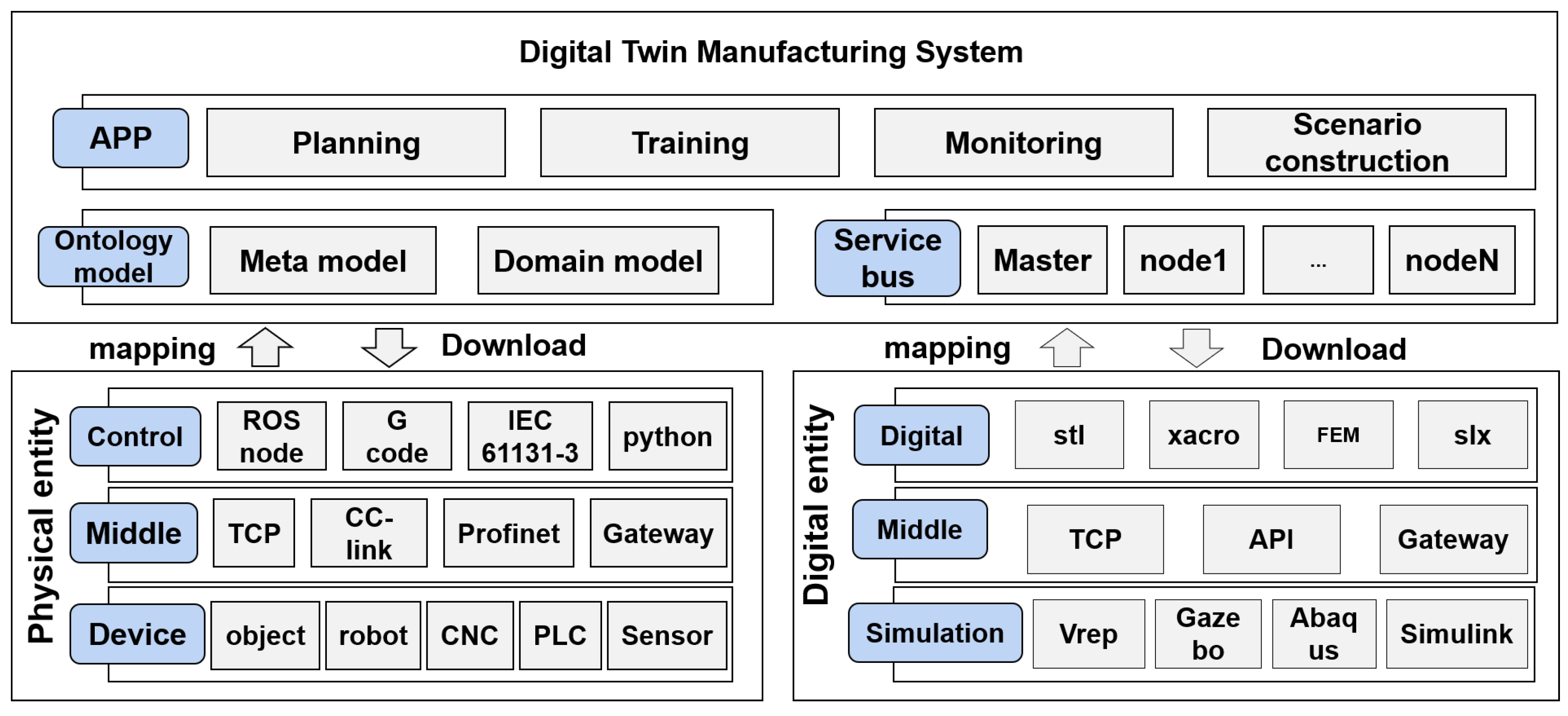
The precision manufacturing process is presented in this section. As shown in Figure 2, the system consists of three parts: the physical entity, the digital entity, and the digital twin manufacturing system (DTMS). Physical entities mainly include all kinds of objects in the precision manufacturing process, including robots, CNC machine tools, PLCs, sensors, processing materials, and working environments. Digital entities describe the physical entities of the virtual space, including the digitized physical entities and all observable data flows and information flows during the precision machining process of the physical entities. The DTMS is a unified abstract description of physical entities and digital entities based on the ontology model. It connects the domain model through a service bus to realize the construction of the digital twin system application of the precision manufacturing process.
The physical entity is based on the traditional control system framework, including the equipment layer, the intermediate layer, and the control layer, covering the underlying equipment and correlation relations of the precision manufacturing system. The underlying equipment includes physical units, such as robots, CNC machine tools, PLCs, sensors, and machining materials; the middleware includes the interaction mode of data flow and information flow between devices; and the control layer mainly refers to the motion controller of the underlying equipment and the running control algorithm program.
The virtual entity is based on multidisciplinary simulation software, including a simulation environment layer, a middle layer, and a digital model layer, including mechanical design, finite element analysis, virtual simulation, and other digital links. The simulation environment layer refers to the virtual simulation environment based on digital models, such as V-rep, Gazebo, ABAQUS, etc.; the middle layer includes the interaction mode of data flow and information flow between digital models; and the digital model layer mainly conducts digital modeling of physical entities, including geometric models, finite element analysis models, multidisciplinary simulation models, and control models.
The DTMS is based on the modeling specification of the metamodel, including the ontology model layer, service bus layer, and application layer, unifying physical entities and virtual entities into the ontology space, and building a system running environment of virtual and real integration through service association. In the DTMS, the service bus is mainly based on the ROS environment, and the ontology model and the application development based on the ontology model are the core of realizing virtual and real integration of the system, which is also the main work of this paper, which will be discussed in detail in the subsequent sections.

3.2. Ontology Model Design

The ontology model is designed to unify the physical models and information models contained in physical and digital entities, ensuring that a common knowledge framework can be shared between the subsystems of the shaping equipment. Moreover, the simulation results can be stored in the knowledge base to realize the reuse and analysis of knowledge.

3.2.1. Ontological Structure

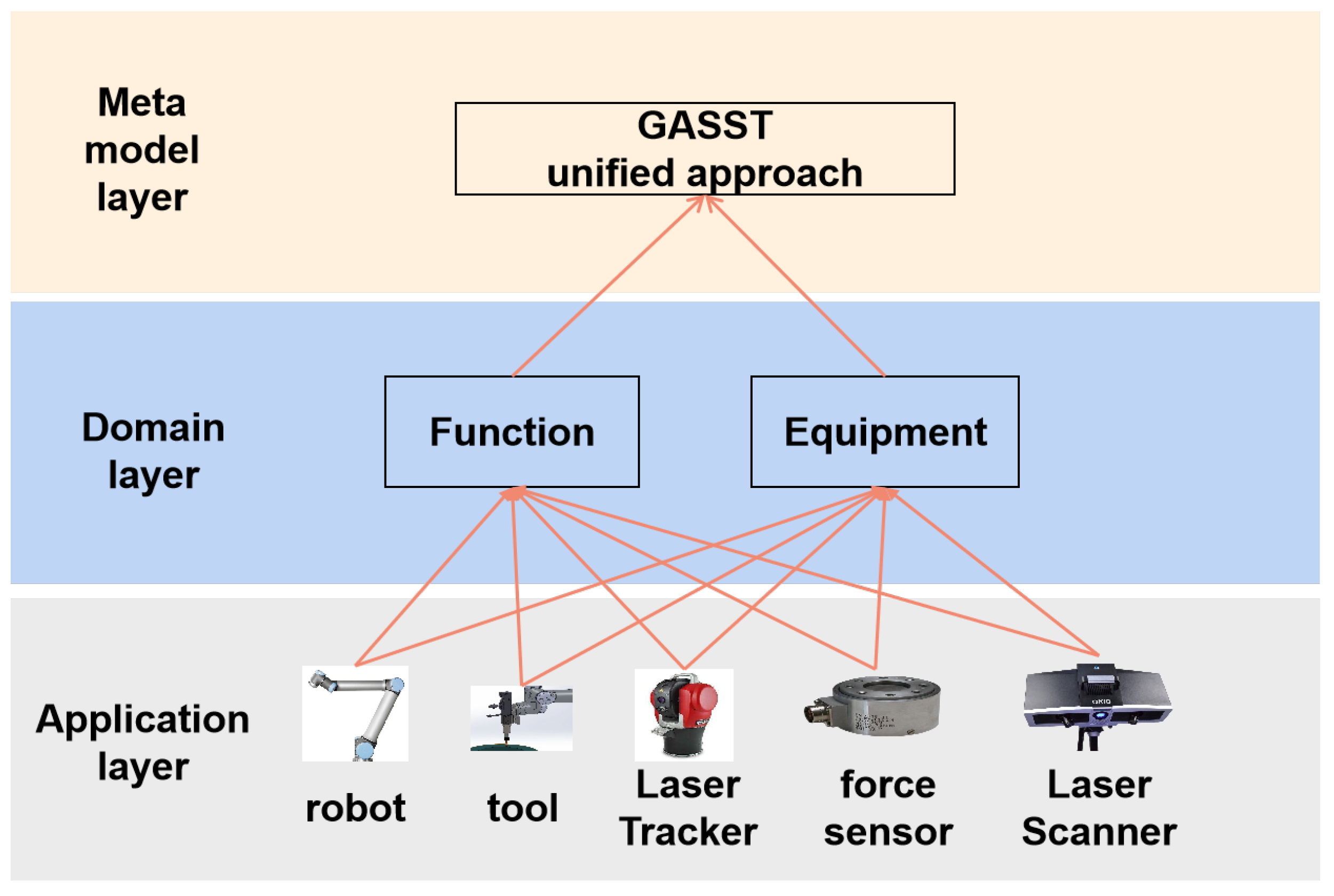
Traditional ontology modeling primarily focuses on the semantic annotation of knowledge, serving as a foundation for knowledge retrieval. However, there is currently no established standard for creating task ontologies, particularly concerning the application and definition within specific fields. To address this gap, this paper proposes an ontology structure, as illustrated in Figure 3. It develops a metamodel for robot application integration and extends this framework to incorporate a field model, ultimately applying it to actual physical systems. This approach provides essential semantic models for subsequent application modeling, task arrangement, and application deployment. Presently, the ontology model is constructed using OWL and Protégé 5.5.

3.2.2. Metal Model Ontology

This paper proposes the implementation of the GASSTA (Graph, Agent, Service, Space, Topic, Association) metamodel with six basic elements: graph, agent, service, space, topic, and relationship. The relationships in the GASSTA model are shown in Figure 4.
A description of the metamodel ontology is shown in Equation (1).
M e t a l _ m o d e l : = { G r a p h , A g e n t , S p a c e , S e r v i c e , T o p i c , A s s o c i a t i o n }
where a graph represents a full cooperative simulation scenario. An agent represents a physical object or subsystem within the scene space. It represents the spatial location of the individual entities in the scene and the coordinate transformation between the entities, or the address of subsystem calculation. A service represents the specific function that the object can provide. A topic represents the interactive information provided by the object. A relationship represents the attribute interactions between agents, as described in Equation (2).
A s s o c i a t i o n : = { C / P , P / S , T r a n s l a t i o n }
where C / S represents the service flow in the collaborative simulation scenario. The arrow root node represents the service provider, and the arrow terminal indicates the service user. P / S represents the information flow in the collaborative simulation scenario. The root node of the arrow represents the topic provider, and the arrow terminal represents the topic user. Translation represents the positional relationship between the physical entity models in the collaborative simulation scenario.
Figure 4 includes five other elements, used for the characterization of a complete collaborative simulation scenario. The agent in Figure 4 includes three elements: space, service, and topic. The connection between Agent1 and Agent2 is topic, service, and space, characterizing the information interaction, service call, and spatial location relationships between agents, respectively. The specific functions of the agent are released through the service method, and the workflow of the service can represent the specific processing process. Semantic description of the model was conducted using the OWL language. Specifically, Protege software was employed to encapsulate the model, and the ontology of the robot shaping system was formalized by defining classes and their attributes. Through this process, the concepts defined in the GASSTA model could be transformed into OWL classes. The data properties of the classes can be used to correlate specific 3D models, program code, text, formulas, and other knowledge information to provide support for the subsequent collaborative simulation code generation.

3.2.3. Domain Ontology

All individuals in the precision manufacturing digital twin system are constructed under the six basic elements, namely graph, agent, space, service, topic, and correlation. According to the domain modeling, both entities and non-entities in the precision manufacturing system can be packaged according to the specific functions of the two-field model. The former can be used to represent a model or method, such as the agent model of force and temperature, and the latter can be used to represent a mechanical arm and a tool. Different graphs can represent different collaborative simulation conditions to complete different simulation tasks. In this way, the GASSTA model provides a standard process and specification for the precision manufacturing system, which can be expanded according to the actual scenario requirements.
(1)
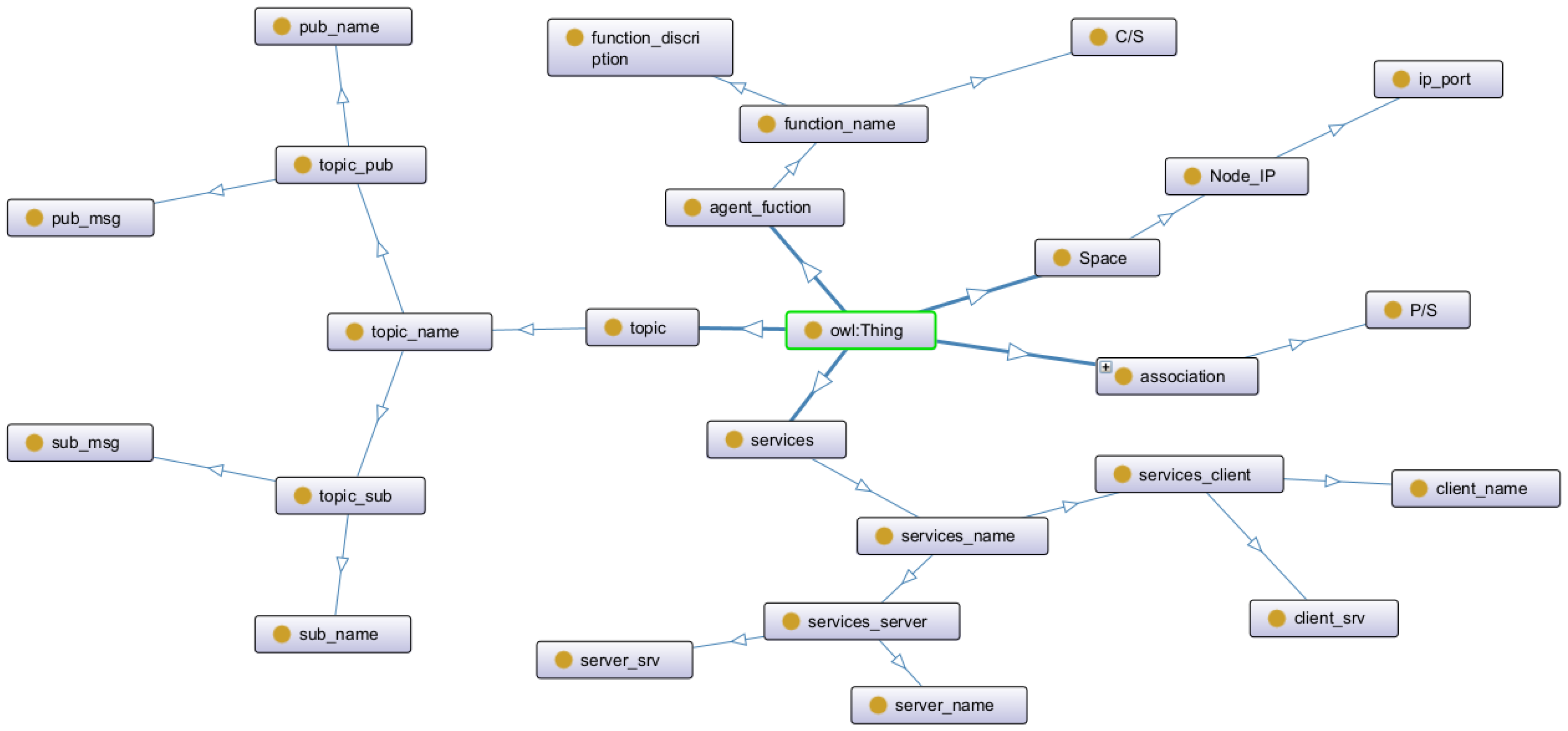
Function ontology—The function ontology is used to characterize the model or method in the system, which is expanded based on the metamodel architecture; the services of the function ontology correspond to an srv file and the source program for the function; the topic corresponds to an msg file, the data format of the topic, and the source program for the function, with the physical equipment to be deployed by the ontology and the call relationship of the corresponding services and topics. Figure 5 depicts the function ontology model.
(2)
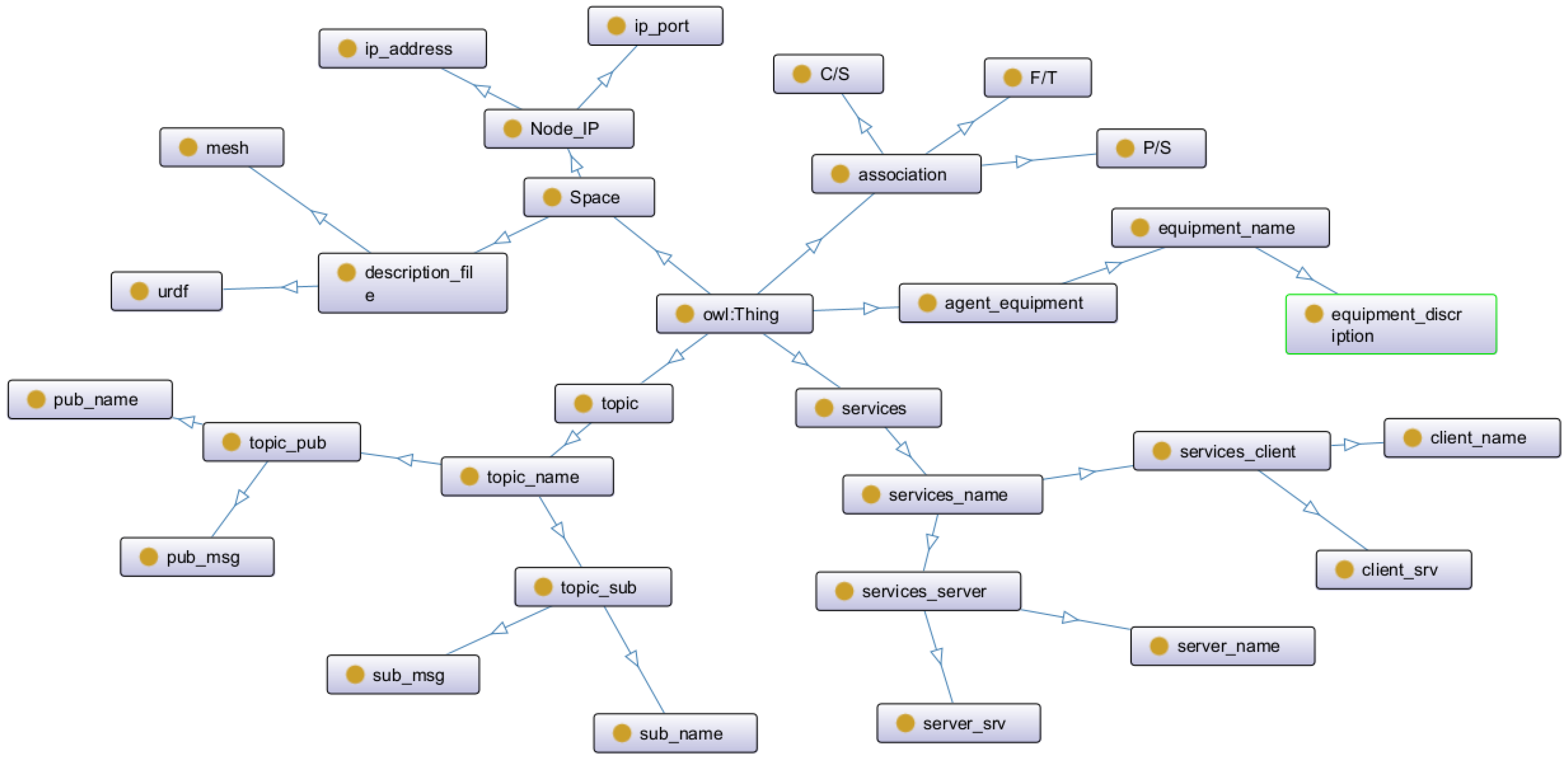
Equipment ontology—This is the collection of equipment categories in the robot shaping system. Unlike the method model, the device ontology adds the spatial relationship of the device and the 3D description file of the device for the subsequent digital twin simulation. At the same time, most of the services provided by the equipment body are network services packaged on the basis of the hardware drive, such as the position control service of the robot. Figure 6 shows the device ontology model.
In general, the domain model is a specific application-oriented instantiation of the metamodel, used to characterize the physical devices or methods in the shaping system and to map the specific functions and interactive information of each part of the system into the services and topics of the agent.

4. Application Layer Design

In the previous section, the metamodel only achieves formal unity for the precision manufacturing system model and whole life cycle consistency. However, how to abstract and reorganize the DTMS model in concrete applications has become a key problem. Based on Java, this paper develops an application layer design tool for the instance model, which can be imported into the specific engineering application model through drag and drop, and provides the graph formal programming environment of the domain model, which has the functions of configuration, arrangement, code generation, and deployment of the domain model.
(1)
Model configuration—Based on the GASSTA specification, entities and algorithms in the system are used as agents, and all agents can be used to generate multiple OWL files. Model instantiation is implemented by using the parameter configuration. The configuration parameters provide detailed information on the processed part, including a detailed description of the processed part; design documents, such as a 3D model; material attribute information, such as Poisson’s ratio, strength, and specific heat; and process requirements, such as machining accuracy, safety constraints, and other information.
(2)
Model arrangement—The actual business process and data flow are realized through correlation between the models, using a line representation with arrows. C/S between services represents the service flow in the collaborative simulation scenario. The arrow root node represents the service provider, and the arrow terminal indicates the service user. P/S between topics represents the information flow in the collaborative simulation scenario. The root node of the arrow represents the topic provider, and the arrow terminal represents the topic user. The translation between spatial attributes represents the positional relationship between physical entity models in the collaborative simulation scenario. The shaping system is finally characterized in the form of graphs, and the corresponding system files are generated.
(3)
Code generation—The choreographed scenario model generates executable programs for the target environment by association.
(4)
Model deployment—The arranged system file contains the interaction between services, topics, spaces, and other information between agents. The code parses the graph information and generates the corresponding program in the form of a functional package according to the ROS node template. After parsing the file, the deployment tool is deployed to the node device according to the IP address, and then, the running scheduling logic is controlled through the master node. Finally, they participate in the simulation process in the form of a ROS node service or topic.

4.1. Code Generation

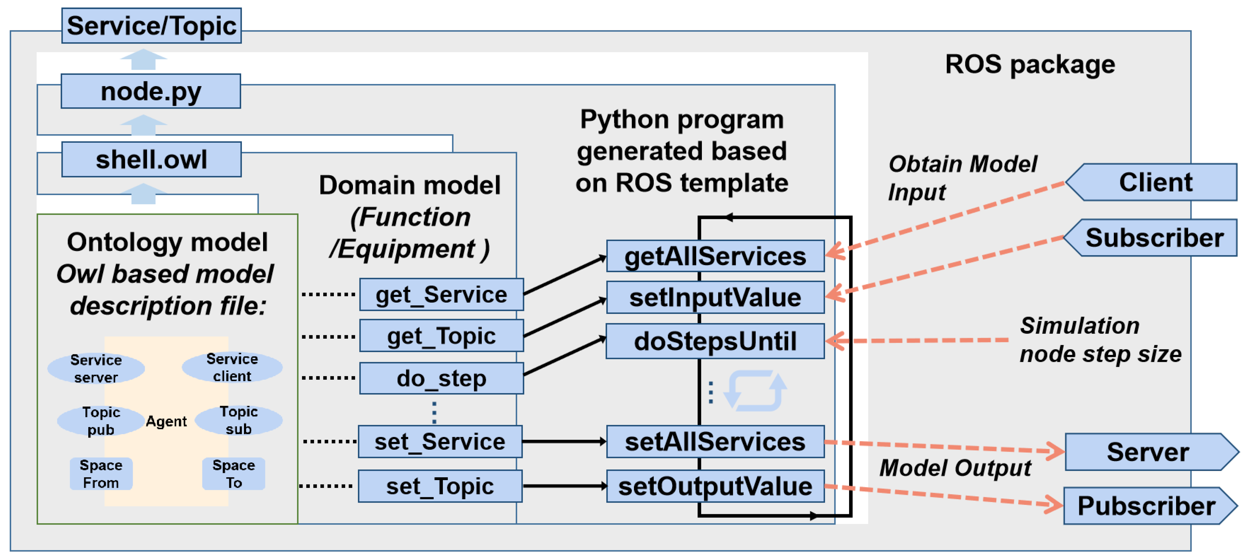
Code generation is central to the development of the DTMS presented in this paper. Application layer design tools for the agent, services, topics, spaces, and other properties in the virtual environment are used to reconstruct the virtual scene. This paper uses the features of distributed deployment in the ROS architecture. Using the ROS code generation principle shown in Figure 7, the ontology model contains instance information in ROS function package-required files and programs.
The ontology choreography tool associates the topic and service corresponding to the agent according to the ROS template selected by the model and generates the corresponding ROS node program, and the algorithm program corresponding to the ontology is integrated into the node by means of callback. All of the nodes are managed via the ROS Master. After the code is generated, the backend does the following based on the configured properties, as shown in Table 1.

4.2. Operation Process of DTMS

The digital twin operation mechanism proposed in this paper is to quickly integrate the ontology model of each subsystem and establish an executable solid propellant grain shaping simulation scenario. Here, we adopted the simulation architecture of ROS as the main environment for virtual simulation. The elements required by the digital twin system can be transformed into the simulation nodes of ROS, the agent model of multidisciplinary simulation can be transformed into specific services, and the information transmission between models can be managed and interacted with through topics. The digital twin operation mechanism proposed in this paper is the operation process of transforming the ontology model into ROS nodes:
(1)
Configuration stage-scene construction—All solid objects in the agent in the graph provide the corresponding URDF model, which can be built in the simulation environment; subobjects provide operational packages that can be run as nodes in ROS.
(2)
Configuration stage-parameter configuration—Based on the design information, the static information of the digital twin simulation includes the solid initial pose; material attribute information, such as Poisson ratio, strength, specific heat, etc.; and process requirements, such as machining accuracy, safety constraints, and other information.
(3)
Initialization stage-scene initialization—The specific location of the entity object is determined by the space attribute, and the location relationship of the entity object is described by translation.
(4)
Initialization phase-service registration and initialization—The specific functions of the entity are published in a service manner.
(5)
Digital twin simulation stage-workflow operation—According to the specific workflow of the task model reasoning, the processing process of the robot shaping system is simulated through the service calling sequence of the ontology model.
(6)
Digital twin simulation stage-single-step calculation—The specific simulation step is determined according to the initialization information, the multidisciplinary simulation is integrated by the agent model, and the simulation is calculated according to the specific solver or executable program.
(7)
Digital twin simulation stage-simulation results—The resulting data of the simulation are stored uniformly according to the ontology model.
In traditional ROS-based simulation, the data correlation between each subsystem usually requires human participation, and data analysis of the simulation results can only provide limited information. With the support of the digital twin operation mechanism, the simulation results of each node can be combined with the ontology model to form a knowledge base and provide a training set for subsequent planning and deployment.
The digital twin under the DTMS architecture is reflected in the following aspects:
(1)
A unified semantic modeling method is adopted to establish the ontology model of multiple agents, which integrates the physical model and the digital model of each piece of physical equipment into the process of solid propellant grain shaping.
(2)
The ontology model is transformed into nodes under the ROS architecture, and each environment of the digital twin is connected through service combination, and data interaction between subsystems is realized through topics.
In conclusion, the data/information between the models and the feasibility and convergence of the system algorithm are verified by the ROS simulation process. On this basis, the generated node program can be deployed to the corresponding physical hardware according to the IP information of the model space attribute. According to the connection relationships between the models in the ontology system file, the ROS nodes are started in order, which can realize stable operation of the whole system.

5. Digital Twin Simulation Verification of the Shaping System

5.1. The Robot Shaping System

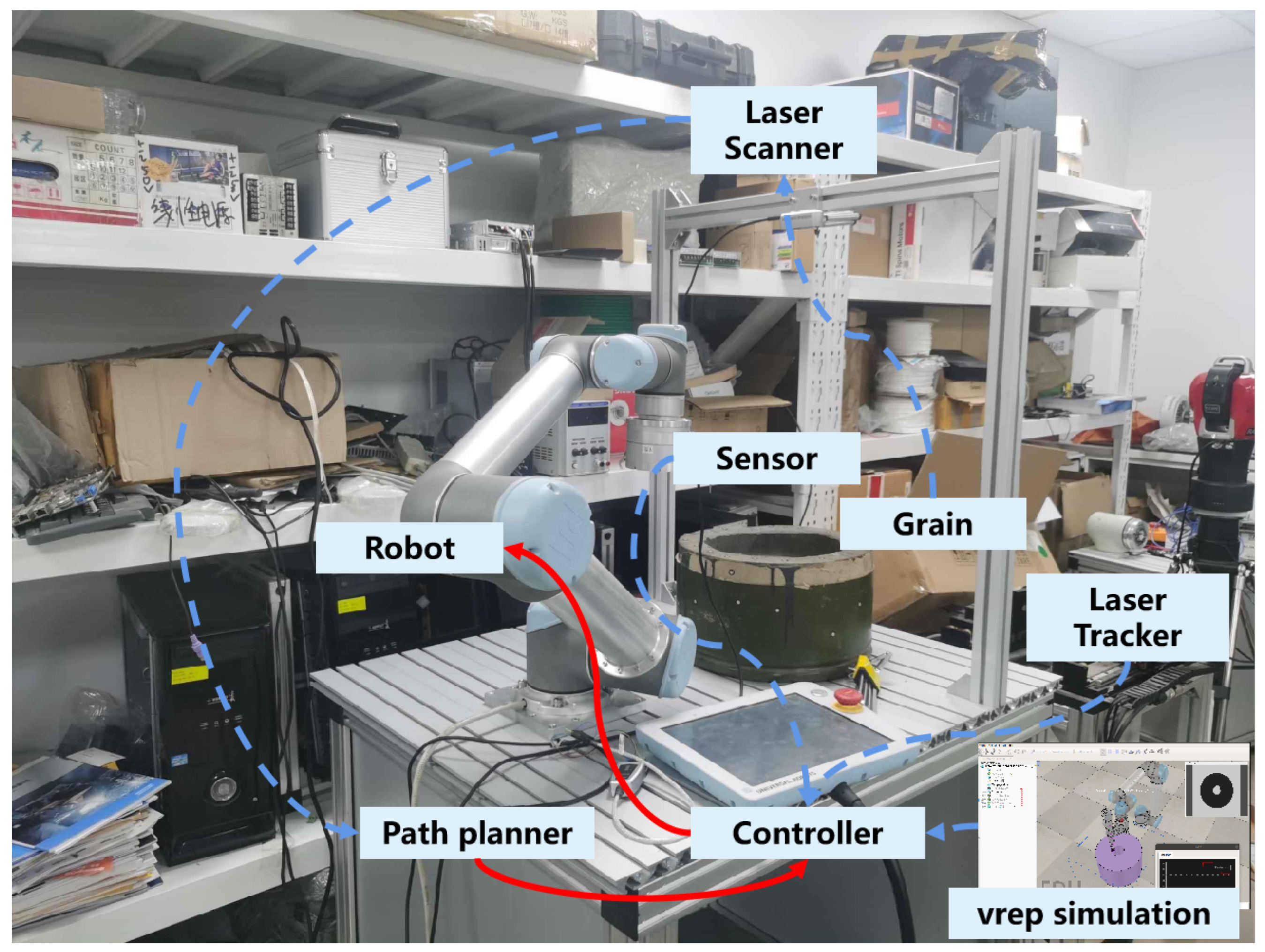
To effectively demonstrate the implementation of the ontology model and the digital twin simulation architecture presented in this paper, it is crucial to provide concrete application examples—specifically focusing on the material reduction manufacturing process for inert solid propellant grains. We therefore showcase the robotic shaping system depicted in Figure 8. This robust system integrates key components—including a sophisticated robot controller, a cutting system, a force sensor, a vision sensor, and a laser tracking instrument—creating a seamless and efficient operational framework. Furthermore, the robot’s online control algorithm, paired with a dynamic virtual simulation environment, is expertly deployed on a dedicated PC, ensuring optimal performance and reliability in real-time applications.
In order to provide shaping precision, the digital twin system needs to provide force, heat, deformation, and other physical quantities to realize the simulation closed loop. One aspect is the simulation results, and the other is the measurement results of the sensing system. The goal of simulation system optimization is shown in Equation (3).
min x J ( π ω ; x ) : = E | | x ^ x | | s . t . x t = f s u r r o g a t e ( s t , x t 1 ) s t = π ( s t 1 ; ω )
where π ω denotes the simulation process, and s represents the simulation state, which encompasses the material’s position and shape, the mechanical arm’s configuration, ambient temperature, and other relevant factors. Each simulation stage depends on specific configuration parameters. Therefore, it is necessary to optimize the parameters ω to ensure that the simulated environment closely matches the real-world conditions, thereby improving the reliability of the simulation results. Here, f s u r r o g a t e represents a surrogate model used to accelerate computation, and the optimal configuration parameters ω are obtained through Equation (3), ensuring the fidelity and accuracy of the simulation system.
Based on this optimized simulation, further design and optimization tasks can be performed, including cutting process planning, cutting path optimization, and flexible manipulator control. Taking cutting path planning as an example, under the constraints of material viscoelasticity, manipulator stiffness, and cutting precision, a joint simulation is conducted based on the GASSTA ontology model to establish an optimized cutting path planning framework, enabling more accurate and reliable path generation.
Specifically, the environmental state at time t is represented as x t , with the state space including the joint angles of the manipulator Ψ t , the center position of the tool’s end-effector e t , the cutting state δ t , and the maximum temperature at the tool-material contact point ξ t , i.e.,
x t = [ Ψ t , e t , δ t , ξ t ]
This comprehensive state definition provides a complete description of the simulation environment, allowing the optimization process to fully account for manipulator motion, cutting dynamics, and thermal effects.
The optimal robot milling strategy can be described by the optimization problem
min l ( τ )
s . t . x t + 1 = f ( x t , u t ) , t = 1 , 2 , , T
where f ( x t , u t ) represents the loss function or the cost function, and the motion trajectory of the robot; the system dynamics function, namely the robot dynamics function, given the current robot state and control amount; the robot state at the next time; and the system control amount are also incorporated into the problem. In the robot milling task, the system dynamics are given by the simulation environment and satisfy the following environmental constraints:
s . t . Ψ t + 1 = f ( Ψ t , u t ) e t = f F K ( Ψ t ) δ t , ξ t = f s u r r o g a t e ( e t 1 , e t ; s s u r f a c e )
where f F K represents the positive kinematic function of the robot, with the specific robot architecture and parameters determined. The UR5 robot is used in this project, and the positive kinematics is implemented using V-rep V3.6.0 simulation software. The agent model is used to represent a finite element analysis because finite element analysis cannot meet the real-time requirements, and the calculation cost is huge. In this paper, the Kriging model is adopted to build a multi-fidelity surrogate model f s u r r o g a t e to improve the computational efficiency with enough accuracy. Although the agent model is not as accurate as a finite element analysis, it still meets the requirements and can greatly accelerate the simulation process.
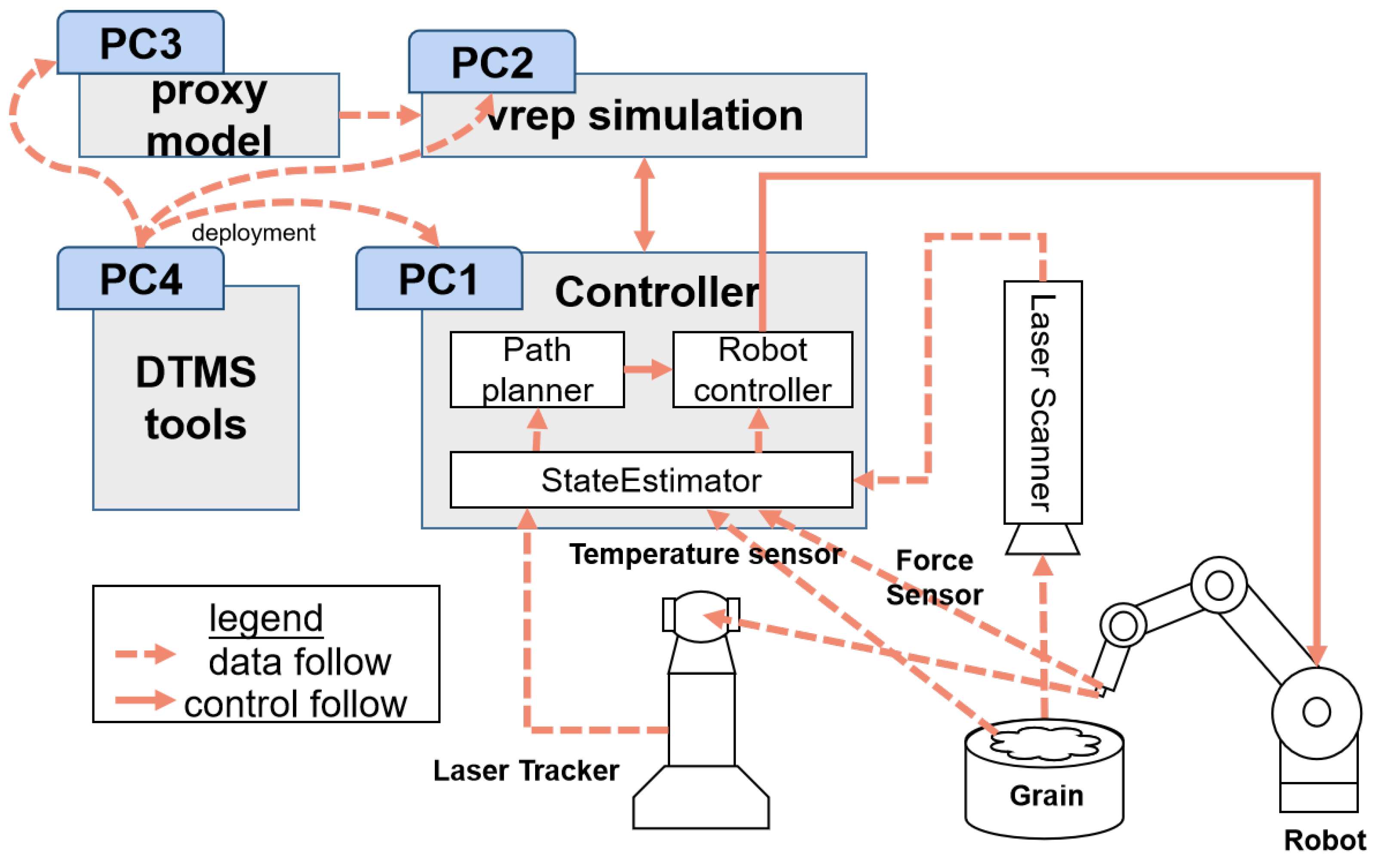
All components of the system are connected through Ethernet or wireless networks. The system structure is shown in Figure 9. The system is finally implemented using ROS simulation architecture, so the processing units included in the system are all run independently on different computers in the way of ROS simulation nodes.

5.2. Ontology Model Design of the Robot Shaping Scene

Referring to Figure 9, all subsystems in the column-shaping scenario can be divided into functions and devices based on physical entities. According to the modeling specification of the GASSTA ontology model, each agent contains three auxiliary elements: service, topic, and space. Each service corresponds to one srv file and the source program for the function implementation; each topic to one msg file, the data format describing the topic, and the source program for the function implementation; and spatial coordinates to describing the location of the entity. The URDF file characterizes the description of the entity itself; the mesh file represents the STL file of the entity itself; and the node IP represents the IP address on which the node is running. Taking the robot cutting system ontology model as an example, the required services are the robot control service and the milling cutter speed control service; the subscribed topics can include a speed control instruction, joint control instruction, torque control instruction, milling cutter speed control instruction, etc.; the spatial coordinate information represents the coordinate information between other entities and the system. At the same time, the model can publish the joint value, speed value, torque value, cutter speed value, etc.; the spatial attributes include the spatial coordinates of the system itself, the 3D description file, and the node IP on which the model runs.
The ontology model of the algorithm in question focuses primarily on the services and topics that can be provided by the method itself. For instance, using the force agent model as an example, this model can offer a service for force simulation and can publish a topic related to the contact force. Additionally, the spatial attributes include the node IP address on which the model operates. Based on these examples and utilizing the GASSTA ontology model, we can abstract all of the elements involved in the robot shaping system and model the robotic shaping process, as illustrated in Table 2. The Protege tool has been used to instantiate the ontology model, and the related files are uploaded to a cloud server for unified management and consistency of the file models. This step also identifies the required agents within the system, along with the services and topics that need to be provided.

5.3. Digital Twin Simulation and Deployment of the System

In the process of digital twin simulation, the ontology configuration tool is developed to represent the basic elements using rectangles. Lines with arrows are used to indicate relationships between elements. Element attributes are represented as an attribute list. The agent in Table 2 can be characterized in the form of an ontology, and the specific algorithm programs are encapsulated into the present body in the form of model properties. With the DTMS tool, illustrated in Figure 10, you can import the ontology model required into the scene and arrange the information flow of the ontology model using connections.
In this paper, V-rep simulation software is used to build the simulation environment of the robot shaping system. The related entity model can be updated through the URDF and mesh files in the spatial attributes, and the initialized spatial pose can be adjusted using the spatial coordinate information. Because V-rep cannot directly read the parameters of the ontology, this paper generates txt profiles to store the pose information on the agent model. The services and data in the V-rep simulation process are also involved in the simulation process through the ROS node services or topics.

5.4. Analysis of the Simulation Results

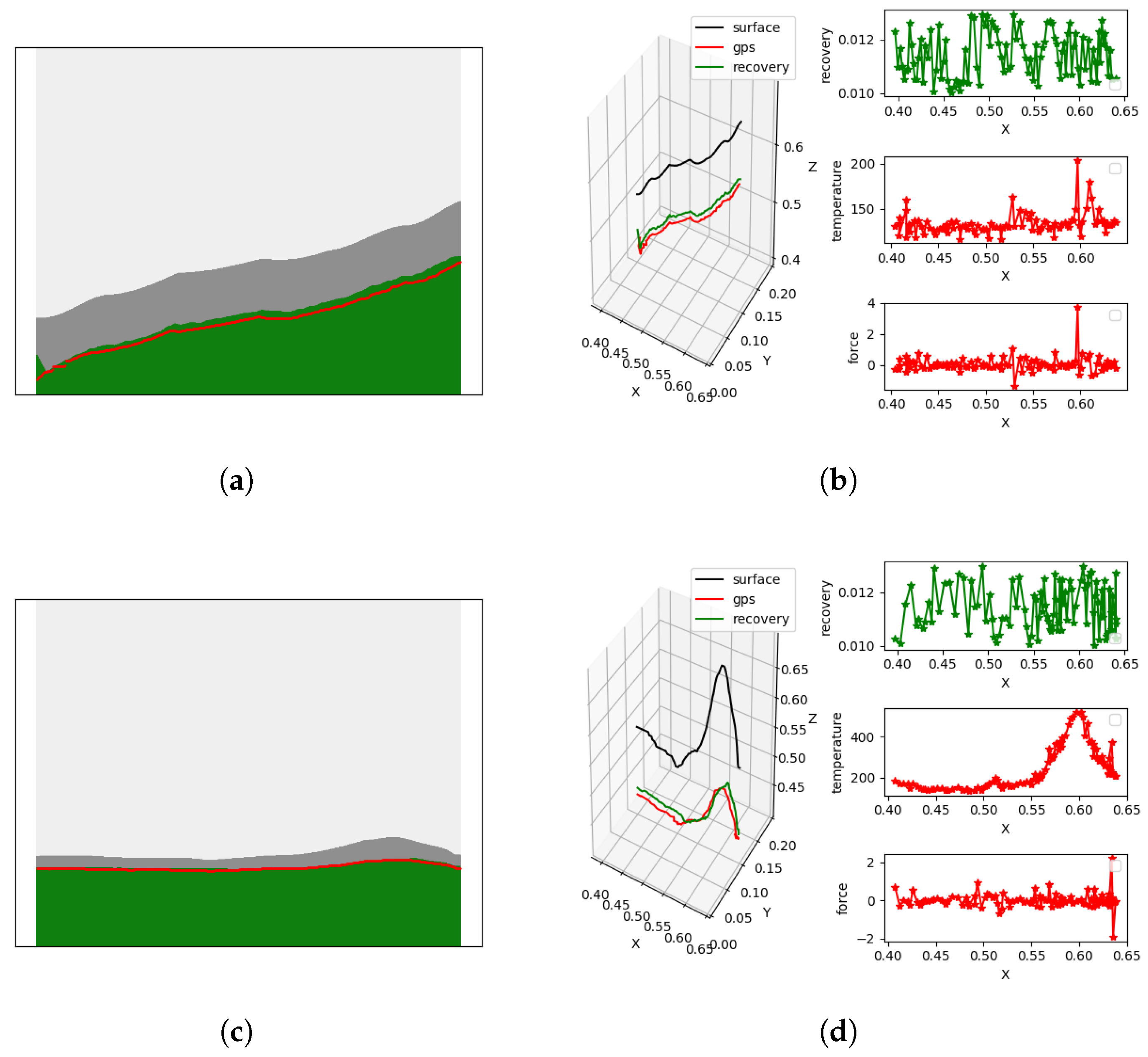
The digital twin simulation system developed in this study was applied to the process of cutting inert solid propellant grains to validate its effectiveness and practicality. By integrating the path planning, strain evolution, temperature distribution, and force response into a unified virtual environment, the system enables comprehensive monitoring and in-depth analysis of the cutting process. As illustrated in Figure 11, the simulation results indicate that the proposed digital twin system can accurately reproduce the material strain, thermal effects, and cutting force variations under different operating conditions. These findings demonstrate that the system possesses reliable predictive capability and real-time feedback functions for complex inert solid propellant grain cutting operations, thereby providing strong support for experimental studies and offering an effective tool for process optimization. Furthermore, when the initial inert solid propellant grain type is changed, only the metamodel of the solid propellant grain needs to be modified, and the subsequent digital twin simulation results will update synchronously. Experimental results further confirm that the system remains effective even after modifications to the geometry and deformation characteristics of the solid propellant grains.

5.5. Analysis of the Physical Experiment Results

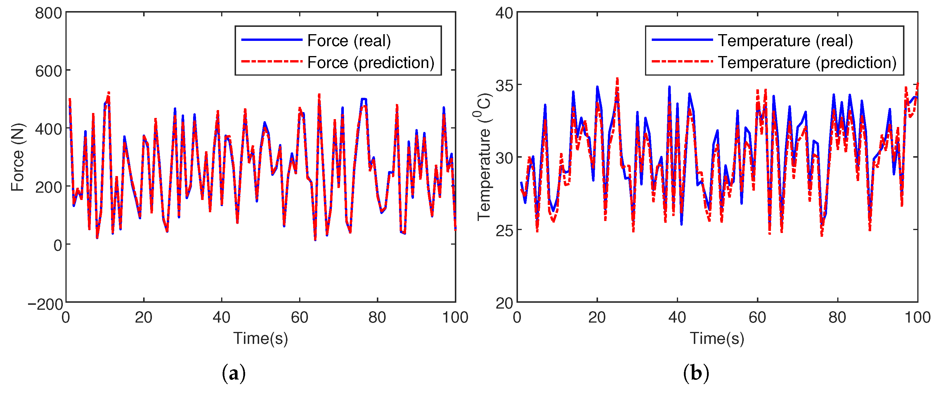
After the simulation experiment, we conducted physical experiments based on the robot shaping system shown in Figure 8. The milling cutter is a double-edged ball cutter, with the rotating speed set to 20 r/s, and the feed speed set to 2 mm/s. As illustrated in Figure 12, under the proposed digital twin architecture, the milling cutter runs stably, and the motion of the robotic arm is controlled by the plan agent. At the same time, through the state estimator agent, it is possible to monitor and predict the temperature and pressure during the robot shaping process effectively.

6. Conclusions

This study presents a digital twin system that exhibits adaptive responsiveness to dynamic variations in the pharmaceutical shaping process, thereby enabling automated design verification and unmanned processing across diverse drug models and size specifications. The proposed GASSTA metamodel establishes a unified foundation for standardized virtual–real integration, ontology-driven configuration, and graph-based topological representation, while the integration methodology incorporates multiphysics coupling simulation, ROS-based functional package generation, and distributed system validation. Experimental results demonstrate that the architecture effectively addresses the challenges of heterogeneous data association, model interaction, and application customization, thus contributing to enhanced precision, scalability, and intelligence in pharmaceutical manufacturing.

Author Contributions

Q.L. designed this study, drafted the manuscript, and acquired funding. P.Z. contributed to methodology development and critical revision of the paper. Q.W. carried out software implementation, data analysis, and visualization. H.Z. supervised the project and provided resources. All authors have read and agreed to the published version of the manuscript.

Funding

This research was funded by the National Key Research and Development Program of China (2024YFB4711105) and the State Key Laboratory of Robotics (2025-Z02-02).

Data Availability Statement

Data are contained within the article.

Conflicts of Interest

The authors declare no conflicts of interest.

References

  1. Urrea, C.; Kern, J. Recent Advances and Challenges in Industrial Robotics: A Systematic Review of Technological Trends and Emerging Applications. Processes 2025, 13, 832. [Google Scholar] [CrossRef]
  2. Ji, W.; Wang, L. Industrial robotic machining: A review. Int. J. Adv. Manuf. Technol. 2019, 103, 1239–1255. [Google Scholar] [CrossRef]
  3. Makulavičius, M.; Petkevičius, S.; Rožėnė, J.; Dzedzickis, A.; Bučinskas, V. Industrial robots in mechanical machining: Perspectives and limitations. Robotics 2023, 12, 160. [Google Scholar] [CrossRef]
  4. Liu, D.; Liu, Z.; Zhao, J.; Song, Q.; Ren, X.; Ma, H. Tool wear monitoring through online measured cutting force and cutting temperature during face milling Inconel 718. Int. J. Adv. Manuf. Technol. 2022, 122, 729–740. [Google Scholar] [CrossRef]
  5. Wu, M.; Guo, Z.; Qian, J.; Reynaerts, D. Multi-Ion-Based Modelling and Experimental Investigations on Consistent and High-Throughput Generation of a Micro Cavity Array by Mask Electrolyte Jet Machining. Micromachines 2022, 13, 2165. [Google Scholar]
  6. Wu, M.; Arshad, M.H.; Saxena, K.K.; Qian, J.; Reynaerts, D. Profile prediction in ECM using machine learning. Procedia CIRP 2022, 113, 410–416. [Google Scholar] [CrossRef]
  7. Wu, M.; Yao, Z.; Verbeke, M.; Karsmakers, P.; Gorissen, B.; Reynaerts, D. Data-driven models with physical interpretability for real-time cavity profile prediction in electrochemical machining processes. Eng. Appl. Artif. Intell. 2025, 160, 111807. [Google Scholar] [CrossRef]
  8. Chen, G.; Zhu, J.; Zhao, Y.; Hao, Y.; Yang, C.; Shi, Q. Digital twin modeling for temperature field during friction stir welding. J. Manuf. Process. 2021, 64, 898–906. [Google Scholar] [CrossRef]
  9. Zhang, Q.; Shen, S.; Li, H.; Cao, W.; Tang, W.; Jiang, J.; Deng, M.; Zhang, Y.; Gu, B.; Wu, K.; et al. Digital twin-driven intelligent production line for automotive MEMS pressure sensors. Adv. Eng. Inform. 2022, 54, 101779. [Google Scholar] [CrossRef]
  10. Saren, Q.; Zhang, Z.; Xiong, J.; Chen, X.; Zhu, D.; Wu, W.; Jin, X.; Shang, K. An accuracy and performance-oriented accurate digital twin modeling method for precision microstructures. J. Intell. Manuf. 2024, 35, 2887–2911. [Google Scholar] [CrossRef]
  11. Huang, Z.; Fey, M.; Liu, C.; Beysel, E.; Xu, X.; Brecher, C. Hybrid learning-based digital twin for manufacturing process: Modeling framework and implementation. Robot. Comput.-Integr. Manuf. 2023, 82, 102545. [Google Scholar] [CrossRef]
  12. Kousi, N.; Gkournelos, C.; Aivaliotis, S.; Giannoulis, C.; Michalos, G.; Makris, S. Digital twin for adaptation of robots’ behavior in flexible robotic assembly lines. Procedia Manuf. 2019, 28, 121–126. [Google Scholar] [CrossRef]
  13. Kampa, A. Modeling and simulation of a digital twin of a production system for industry 4.0 with Work-in-Process synchronization. Appl. Sci. 2023, 13, 12261. [Google Scholar] [CrossRef]
  14. Matulis, M.; Harvey, C. A robot arm digital twin utilising reinforcement learning. Comput. Graph. 2021, 95, 106–114. [Google Scholar] [CrossRef]
  15. Saavedra Sueldo, C.; Perez Colo, I.; De Paula, M.; Villar, S.A.; Acosta, G.G. ROS-based architecture for fast digital twin development of smart manufacturing robotized systems. Ann. Oper. Res. 2023, 322, 75–99. [Google Scholar] [CrossRef]
  16. Lu, J.; Yang, Z.; Zheng, X.; Wang, J.; Dimitris, K. Exploring the concept of Cognitive Digital Twin from model-based systems engineering perspective. Int. J. Adv. Manuf. Technol. 2022, 121, 5835–5854. [Google Scholar] [CrossRef]
  17. Asif, M.E.; Rastegarpanah, A.; Stolkin, R. Robotic disassembly for end-of-life products focusing on task and motion planning: A comprehensive survey. J. Manuf. Syst. 2024, 77, 483–524. [Google Scholar] [CrossRef]
  18. Vazirpanah, M.; Attarzadeh-Niaki, S.H.; Salimi-Badr, A. Ros-based co-simulation for formal cyber-physical robotic system design. In Proceedings of the 2022 27th International Computer Conference, Computer Society of Iran (CSICC), Tehran, Iran, 23–24 February 2022; pp. 1–5. [Google Scholar]
  19. Li, Y.; Chen, J.; Hu, Z.; Zhang, H.; Lu, J.; Kiritsis, D. Co-simulation of complex engineered systems enabled by a cognitive twin architecture. Int. J. Prod. Res. 2022, 60, 7588–7609. [Google Scholar] [CrossRef]
  20. Wang, S.; Zhang, J.; Wang, P.; Law, J.; Calinescu, R.; Mihaylova, L. A deep learning-enhanced Digital Twin framework for improving safety and reliability in human–robot collaborative manufacturing. Robot. Comput.-Integr. Manuf. 2024, 85, 102608. [Google Scholar] [CrossRef]
  21. Rakhtala, S.M.; Ghayebi, R. Real time control and fabrication of a soft robotic glove by two parallel sensors with MBD approach. Med. Eng. Phys. 2022, 100, 103743. [Google Scholar] [CrossRef] [PubMed]
  22. Gan, J.; Zhou, Z.; Yu, A.; Ellis, D.; Attwood, R.; Chen, W. Co-simulation of multibody dynamics and discrete element method for hydraulic excavators. Powder Technol. 2023, 414, 118001. [Google Scholar] [CrossRef]
  23. Huynh, H.N.; Assadi, H.; Rivière-Lorphèvre, E.; Verlinden, O.; Ahmadi, K. Modelling the dynamics of industrial robots for milling operations. Robot. Comput.-Integr. Manuf. 2020, 61, 101852. [Google Scholar] [CrossRef]
Figure 1. Manufacturing mode based on the digital twin.
Machines 13 00898 g001
Figure 2. Architecture diagram of digital twin realization of the precision manufacturing process.
Machines 13 00898 g002
Figure 3. Structure of modular ontologies for the robot shaping system.
Machines 13 00898 g003
Figure 4. GASSTA ontology model.
Machines 13 00898 g004
Figure 5. GASSTA function model.
Machines 13 00898 g005
Figure 6. GASSTA equipment model.
Machines 13 00898 g006
Figure 7. Digital twin simulation following the ROS code generation principle.
Machines 13 00898 g007
Figure 8. The robot shaping system—testbed.
Machines 13 00898 g008
Figure 9. DTMS structure diagram of the robot shaping system.
Machines 13 00898 g009
Figure 10. Flow chart of DTMS implementation of the robot shaping system.
Machines 13 00898 g010
Figure 11. Simulation verification of a digital twin system for inert solid propellant grain cutting. (a) Scenario 1: digital twin simulation path planning. (b) Strain, temperature, and force variations in Scenario 1 under digital twin simulation. (c) Scenario 2: digital twin simulation path planning. (d) Strain, temperature, and force variations in Scenario 2 under digital twin simulation.
Machines 13 00898 g011
Figure 12. Physical experiment verification of a digital twin system for inert solid propellant grain cutting. (a) Temperature measurement values and predicted values during the shaping process. (b) Force measurement values and predicted values during the shaping process.
Machines 13 00898 g012
Table 1. The process of the configuration.
1Configuration process
2Create functional packages, and each agent corresponds to one or more functional packages.
3Create the msg folder, and import the msg file that originates from the ontology model.
4Modify the CMakeLists.txt document.
5Modify the package.xml
6Generate pub files and sub files based on the template.
7Compile and configure the environment variables.
Table 2. Definition of the robot shaping system agent.
AgentCall the ServiceSubscribe to the TopicRender ServicesPost a Topic
V-rep_nodeFormal simulationDeformation quantityLocation control serviceRobot cartesian data
Force simulationContact forcePhoto serviceRobot joint data
Temperature simulationTemperature scalePosition reading servicePoint cloud data
Robot controlJoint control
PlanPhoto servicePoint cloud dataPlanning servicesPlanning trajectory
Contact force
Temperature scale
Planning servicesPlanning trajectoryRobot controlJoint control
Robot controlLocation servicesRobot Cartesian
Position reading serviceRobot joint value
Laser tracker data Robot tcp data
State estimator Temperature-sensor data Temperature scale
Force sensor Contact force
Temperature agent Temperature simulationTemperature scale
Force agent Force simulationContact force
Formal agent Formal simulationDeformation quantity
Disclaimer/Publisher’s Note: The statements, opinions and data contained in all publications are solely those of the individual author(s) and contributor(s) and not of MDPI and/or the editor(s). MDPI and/or the editor(s) disclaim responsibility for any injury to people or property resulting from any ideas, methods, instructions or products referred to in the content.