Article

Transient Stability-Oriented Nonlinear Power Control of PMSG-WT Using Power Transfer Matrix Modeling with DC Link Behavior

by
Muhammad Ali Bijarani
1,
Ghulam S. Kaloi
1,
Mazhar Baloch
2,*,
Rameez Akbar Talani
1,
Muhammad I. Masud
3,
Mohammed Aman
4 and
Touqeer Ahmed Jumani
2
1
Department of Electrical Engineering, Quaid-e-Awam University of Engineering Science and Technology, Nawabshah 67450, Pakistan
2
Department of Electrical Engineering and Computer Science, College of Engineering, A’Sharqiyah University, Ibra 400, Oman
3
Department of Electrical Engineering, College of Engineering, University of Business and Technology, Jeddah 21361, Saudi Arabia
4
Department of Industrial Engineering, College of Engineering, University of Business and Technology, Jeddah 21361, Saudi Arabia
*
Author to whom correspondence should be addressed.
Machines 2025, 13(10), 886; https://doi.org/10.3390/machines13100886
Submission received: 19 August 2025 / Revised: 16 September 2025 / Accepted: 17 September 2025 / Published: 26 September 2025
(This article belongs to the Section Electrical Machines and Drives)

Abstract

In this paper, a nonlinear power transfer matrix model is presented for power control of Permanent Magnet Synchronous Generator (PMSG) wind turbines, incorporating the DC link dynamics to account for transient stability, thereby clarifying the technical aspect and purpose. The rising penetration of wind turbines (WTs) into the power grid necessitates that they remain connected during and after faults to ensure system reliability. During voltage dips, the stator and grid-side converter (GSC) of a permanent magnet synchronous generator (PMSG) system are directly impacted by the sudden voltage changes. These disturbances can induce large transient voltages and currents in the stator, which in turn may lead to uncontrolled current flow in the rotor circuit and stress the converter components. Moreover, Low Voltage Ride-Through (LVRT) is a critical requirement for grid connection to Wind Energy Conversion Systems (WECS). It ensures that WTs remain connected and operational during short periods of grid voltage dips (faults), instead of disconnecting immediately. This capability is essential for maintaining grid stability. However, in this paper, the authors propose an LVRT scheme for a grid-connected PMSG-based WECS. A sequence of attempts was performed to validate the effectiveness of the proposed control scheme under fault conditions and to improve its overall performance.

1. Introduction

Wind energy is increasingly being utilized as a major source of power generation due to its clean nature and is rapidly expanding across the globe. With the global population rising, energy demand is also growing [1]. As conventional energy sources are being depleted, harnessing wind energy has become increasingly important, and its demand is expected to rise in the coming years [2]. In a wind turbine energy conversion system, different generators are commonly used, including DFIGs and PMSGs. DFIGs are more complex and costly compared to PMSGs. PMSGs offer high efficiency as compared to DFIGs [3]. PMSGs offer design features, including gearless construction, which decreases the cost of maintenance. Their capability lies in producing power at varying wind speeds, making them reliable for optimizing wind power generation [4]. However, PMSGs offer several advantageous characteristics, are widely used in wind energy systems [5,6]. The WTs function at either variable or fixed speeds. Variable-speed wind turbines (VSWTs) are controlled using power electronic equipment, and synchronous machines are employed based on the control scheme [7]. The VSWTs have become more efficient and are widely adopted in recent years [1,8]. In wind farms, grid voltage dips, whether symmetrical or unsymmetrical, along with major faults, can adversely influence the working efficiency of PMSG-based wind turbines. Maintaining system stability under such unbalanced conditions is essential [9]. However, conventional control strategies have failed to ensure stability during voltage surges. For smooth and stable PMSG operation, protecting the stator windings from overvoltage is crucial [10]. These windings may be damaged by power surges if not properly safeguarded. Although much research aims to protect PMSGs from power surges, current methods have proven insufficient for system stability. Traditional Proportional-Integral (PI) controllers have also not improved performance or ensured stability during fault conditions. To address this, Low Voltage Ride Through (LVRT) capability has been introduced. LVRT refers to the ability of wind turbines to remain connected to the grid and generate reactive power during grid faults [11,12]. A common method for protecting the PMSG during faults is to connect a crowbar resistor to the rotor windings. This prevents the machine side converter (MSC) from disconnecting during failures [13]. Crowbar circuits shield electrical circuits from overvoltage caused by power surges [14], protecting the generator’s stator windings and ensuring reliable PMSG operation. In PMSG-based wind power systems, the short-circuit current (SCC) can be managed via the power converter. However, SCC formulas are not applicable during transient states, as they cannot accurately represent the system’s dynamic behavior under faulty conditions due to the complexity of power system configurations [15]. Symmetrical short circuits are a common cause of power failures in electrical systems. Despite symmetrical voltages, transient responses are complex due to the variability of system parameters [16]. Therefore, a nonlinear dynamic model of the PMSG, coupled with a feedback linearization control approach, is used to achieve the desired performance under fault conditions [17]. This paper is organized into ten sections. Section 1 provides the introduction. Section 2 covers the modeling of the wind turbine’s mechanical power. Section 3 addresses the modeling of the PMSG wind turbine system in the dq reference framework. Section 4 discusses the controller design and analysis of the feedback control system. Section 5 offers an assessment of the stability of the feedback control method. Section 6 focuses on the DC-link voltage controller. Section 7 addresses the angular speed operation controller. Section 8 provides system performance evaluation and results, while Section 9 concludes the paper, and Section 10 addresses future work and discussion.

1.1. Related Work

This paper proposes a nonlinear back-stepping controller for regulating the generator’s rotational speed, with its stability verified through a Lyapunov-based analysis. A key drawback of this approach is that it controls the generator speed without explicit knowledge of wind speed, which limits its effectiveness [18]. To overcome this limitation, a nonlinear sliding mode control strategy is introduced to enhance the dynamic performance of the permanent magnet synchronous generator (PMSG), thereby ensuring stable power transfer to the grid. In this framework, a proportional–integral (PI)-based sliding surface is designed, and Lyapunov stability theory is applied to guarantee asymptotic stability of the closed-loop system [19]. Additionally, transient stability and DC-link voltage regulation during LVRT are addressed. A time–frequency analysis based on the Hilbert transform is employed to characterize nonlinear oscillations, and the study demonstrates that such oscillations, along with system stability, are strongly influenced by active power variations [20].

1.2. Research Contribution

The research contribution of this paper is discussed as follows:
(1)
In this paper, a nonlinear power transfer matrix approach is applied to model the dynamic behavior of a PMSG-based wind energy conversion system. Unlike conventional models that rely on voltage, current, and flux linkage as state variables, the proposed nonlinear power transfer matrix employs instantaneous active and reactive powers as the state variables.
(2)
To achieve the effective regulation of active and reactive power, a Lyapunov-based stability scheme is incorporated into the conventional controller, thereby guaranteeing the stability of the nonlinear system under uncertain wind conditions.
(3)
During the fault circumstances, the grid voltage can sag. LVRT-capable generators inject reactive power to support voltage recovery.
(4)
After the fault is cleared, LVRT ensures a smooth transition back to normal operation without unnecessary tripping and reconnection delays.

2. Modeling of Wind Turbine’s Mechanical Power

The mechanical power extracted by a WT is given by Equation (1) [17,21].
P m = 1 2 ρ π R 2 T C p λ , β v 3 w i n d
As ρ represents the density of air; R T shows the turbine blade radius; v shows the wind speed; and Equation (2) represents the WT power coefficient that can be computed by employing the tip speed ratio (TSR) λ and blade pitch angle β , and Equations (3) and (4) become the following:
C p ( λ , β ) = 0.22 ( 116 λ i 0.4 β 5 ) e 12.5 λ i
1 λ i = 1 λ + 0.08 β 0.035 β 3 + 1
λ (TSR) can be defined as follows:
λ = ω r o t R T ν w i n d

3. PMSG Wind Energy System Model Based on Power Components

The power converter adds an MSC for the generator’s speed control and a GSC for inserting power into the system. Real and reactive powers for GSC with passive sign convention in the synchronous frame of reference are given in Equation (5).
p g ( t ) q g ( t ) = 3 2 v s d v s q v s q v s d i g d i g q
where V s d and Vsq represent the stator voltages, and i g d and i g q represent grid-side converter currents appearing in the synchronous frame of reference, respectively. Resolving Equation (5) will result in Equations (6) and (7), whereby we achieve the following:
i g d i g q = K v p g ( t ) q g ( t )
p s ( t ) q s ( t ) = 3 2 v s d v s q v s q v s d i s d i s q
Correspondingly, the real and reactive power elements of PMSG resolved in about stator currents are in Equation (8), and we achieve the following:
K v = 2 3 v s 2 v s d v s q v s q v s d , v s = v s q 2 + v s d 2
Stator current components are provided in Equation (9):
i s d i s q = K v p s ( t ) q s ( t )

3.1. Modeling of PMSG Wind Turbine System in dq Reference Frame

Voltage and flux equations are given in Equations (10)–(13) summed up as follows:
V d s V q s = λ . d s λ . q s + ω s 0 1 1 0 λ d s λ q s + R s 0 0 R s I d s I q s
V d r V q r = λ . d r λ . q r + ( ω s ρ ω r ) λ q r λ d r 0 1 1 0 + R r 0 0 R r I d r I q r
λ d s λ q s = L s 0 0 L s I d s I q s + L m 0 0 L m I d r I q r
λ q r λ d r = L r 0 0 L r I d r I q r + L m 0 0 L m I d s I q s
Replacing Equations (12) and (13) within Equation (10) for I d s d t and I q s d t , we obtained Equation (14) as follows:
I d s d t I q s d t = a 1 ω s ω s a 1 I d s I q s + a 2 a 3 a 3 a 2 I d r I q r + p L m 2 ω r σ L s L r 0 0 I d s + L m σ L s L r 0 0 L m σ L s L r V d r V q r + a 2 a 3 a 3 a 2 I d r I q r + p L m 2 ω r σ L s L r 0 0 I d s + L m σ L s L r 0 0 L m σ L s L r V d r V q r + 1 σ L s 0 0 1 σ L s V d s V q s
Replacing Equation (7) with Equation (14), the subsequent Equation (15) can be achieved:
2 3 α 1 , b 1 ω s l i p ω s l i p 2 3 α 1 b 1 P s Q s + α 1 R r V d g α 1 R r V q g α 1 R r V q g α 1 R r V d g λ d s λ q s + p α 1 L r V q g V d g V d g V q g λ d s λ q s ω r α 1 L m V d g V q g V q g V d g V d r V q r + α 1 L r V g 2
The stator flux equations can be obtained by substituting I s q and I s d from Equation (7) into Equation (10). Subsequently, λ s d and λ s q are resolved and expressed in Equation (16).
λ d s d t λ d q d t = α 3 R r V d g R r V q g R r V q g R r V d g P s Q s + 0 ω s ω s 0 λ q s λ d s
The nonlinear model of the PMSG equation of wind turbine torque and rotor model is provided as Equation (17):
d d t ω r = P J T e P J T m
where P ,   J and T m represent the number pole pairs, the rotor inertia, and the mechanical torque, respectively. The electric torque is taken into consideration as in Equation (18), yielding the following:
T e = 3 2 p ( λ d s I d r + λ d s I q r )
In Equations (12) and (13), the electric torque and the dynamic model input are mechanical torque, as shown in Equation (18). It can be explicit in terms of active and reactive power. By rearranging Equation (17) in Equation (18), the equation can be attained as in Equation (19), and we get:
d d t ω r = P 2 J V s λ s q P s + P 2 J V s λ s d Q s P J T m

3.2. Grid-Side Converter and Filter Model

The filter and d q model of GSC in Equations (20) and (21) are given as follows:
V s d q = V g d q + L f d i g d q d t + j ω e L f i g d q + τ f i g d q
where L f and R f show the inductance and resistance of the filter, respectively, and the index weighs variables at the GSC. Replacing Equation (6) in Equation (20) produces Equation (21):
P g d t Q g d t = b 3 ω s ω s b 3 P g Q g 1.5 V d g L f V q g L f V q g L f V d g L f V d f V q f + 1.5 V g 2 L f 0
Active power P r dispatched to the rotor is given in Equation (22):
P r = 3 2 V r d I r d V r q I r q
Using Equations (7), (12), and (13), P r can be computed as Equation (23).
P r = I s ( V d s V r d   +   V q s V r q ) I m V s 2 P s + I s ( V q s V r d   +   V d s V r q ) I m V s 2 Q s + 1.5 λ d s I m V r d + 1.5 λ q s I m V r q
Power losses were ignored due to small quantities. By taking the identical actual power of the dynamic model of PMSG, as it may be achieved in the DC converter and DC link model node in Equation (24):
V d c ( t ) I d c ( t ) = P g ( t ) P r ( t ) P l o s s ( t )
where P g ( t ) describes the grid power; P r ( t ) describes the active power of the rotor; and Ploss(t) describes the power losses, containing the copper losses and the converter switching losses.

4. Controller Design and Analysis of a Feedback Control System

Active and Reactive Power Controller Design

This research utilizes vector-oriented control alignment based on V q g for the MSC and GSC. Thus, the components of the flux of a PMSG in a field-oriented frame of reference with V d g = 0 and V d q = V g = A (constant) can be obtained, i.e., V q r , V q f , V d r , and V d f correlates with P s , P g , Q s , and Q g separately. Subsequently, a continuous controller with PI output feedback is implemented, allowing the controlled input to individually manage the states of power at the intended source. Hence, the subsequent Proportional Integral controller’s feedback output is MSC, considering MSC. Proposed PI controllers for RSC output feedback are given as follows in Equations (25) and (26):
V d r = k p Q r Q s + k I Q r 0 1 ( Q s Q s r e f ) d τ
V q r = k P P r P s + k I P r 0 1 ( P s P s r e f ) d τ + L r L m V g
The grid-side converters, suggested for the feedback PI controller’s output, are given in Equations (27) and (28):
V d f = k P Q f Q g + k I Q f 0 1 ( Q g Q g r e f ) d τ
V q f = k P P f P g + k I P f 0 1 ( P g P g r e f ) d τ + V g
where the gains k P Q f , k I Q f , k P P f , k I P f are scalar and positive. The right-hand part, last term V q r and V q f are attached for reliability reasons with the valuation of V g constant and specified.
Controller Equations (25)–(28) are built upon a general grid voltage-oriented control (VOC) design. In an open-loop system, by integrating these controllers, the full model is expressed in VOC alignment rather than the conventional field arrangement method. This represents a notable advancement, as it eliminates the requirement for measuring flux or estimation. Nonetheless, stability must be analytically verified since the established benefits of the field-oriented approach for demonstrating stability are not applicable here. To achieve this, the complete closed-loop representation of the system and controller is presented in a manner that allows for a thorough stability analysis in voltage orientation as in Equation (29).
P S . = 2 3 α 1 b 1 + α 1 b 2 k P P r P s ω s l i p Q s p α 1 L r V g λ d s ω r + α 1 R r V g λ d s α 1 α q r z q r
By exchanging Equations (25) and (26) within Equation (15) for P s , the following Equation (30) can be obtained:
Q s . = ω s s l i p P s 2 3 α 1 b 1 + α 1 b 2 k P Q r Q s + p α 1 L r V g λ q s ω r + α 1 R r V g λ d s α 1 α d r z d r
Now replacing Equations (25) and (26) with Equation (21) for P g , yields the succeeding Equation (31):
P g = b 3 + 3 2 b 4 k P P f P g ω s Q g α q f z q f
Replacing Equations (25) and (26) with Equation (21) for P g yields Equation (32), and we get the following:
Q g = ω s P g b 3 + 3 2 b 4 k P Q f Q g α d f z d f
Re-arranging Equations (16) and (19), Equations (33)–(35) can be obtained as follows:
ω r = p α 2 L r V g λ d s P s p α 2 L r V g λ q s Q s b J ω r 1 J T m
λ d s = α 3 R r V g Q s + ω s λ q s
λ q s = α 3 R r V g P s ω s λ d s

5. Stability Analysis of the Feedback Control System

Considering the 11th feedback control system and taking into account the following Lyapunov function H in Equation (36):
H = 1 2 α 1 ( P s 2 + Q s 2 ) + 1 2 ( P g ) 2 + 1 2 ( Q g ) 2 + 1 2 α 2 ω r 2 + 1 2 α 3 ( λ d s 2 + λ q s 2 ) + 1 2 ( z d r 2 + z q r 2 + z d f 2 + z q f 2 )
H is the time derivative, denoted in Equations (29)–(35), and can be defined as H . = x d T R d x d 0 . The derivative of H is computed from the utilization of Equations (20) and (37):
H . = 2 3 b 1 + b 2 k P P r P s 2 2 3 b 1 + b 2 k P Q r Q s 2 ( b 3 + 3 2 b 4 k P P f ) ( P g ) 2 ( b 3 + 3 2 b 4 k P Q f ) ( Q g ) 2 b 5 + y T u c l
See Appendix A for detailed parameters of Equations (29)–(37). Since the parameters are positive being functions of the grid voltage magnitude, the generator, and the controller gain the first five quadratic terms of the time-derivative of the storage function in Equation (37) are non-positive. Consequently, Equation (37) leads to the following proposition.
To begin the analysis of stability, and to determine that the system of the eleventh order is Input-to-State Stable (ISS). Concerning, it is to evaluate the unforced feedback control of the eleventh order, by setting u c l = O 5 × 1 . The objective is to demonstrate that the method possesses a Global Exponential Stability (GES) balance at the beginning of the point, which subsequently guarantees the Input-to-State Stability (ISS) of the 11th-order system influenced by certain bounded external factors u c l .
Establishing Global Exponential Stability (GES) beginning of the unforced system is a challenging endeavor because identifying an appropriate Lyapunov function is quite complex. Therefore, we will begin by employing the previously identified storage function H .
It is clear through Equation (37) for the unperturbed method, a derivative of the time of the function of storage is non-positive, i.e., H ˙ 0 . That certainly demonstrates Lyapunov’s stability; the subsequent suggestion is valid.
The eleventh-order unforced feedback control possesses a state vector x 2 z T that is independent, and may be expressed in Equations (38) and (39):
M x ˙ 2 z ˙ = J ( x 2 R ) x 2 z
M 11 0 5 × 6 0 6 × 5 M 22 x d . x u . = J d ( x d u ) R d D D T J u x d x u
With x d = P s Q s P g Q g ω r T being the r = 5 damped states and x u = λ d s λ d s z d r z q r z d f z q f T being the n r = 6 un-damped states of the n = eleventh-order state vector x d u = x 2 z T = x d x u , the matrix expressions are related to Equations (38) and (39).

6. DC-Link Voltage Controller

The voltage controller used is as follows:
P g r e f = k P d c V d c + k I d c 0 1 ( V d c r e f V d c ) d τ
Equation (40) defines the DC-voltage dynamics, and it is noted that the usual method of evaluation regarding the grid-side converter takes into account the DC current as a disturbance input on the opposite side. The closed-loop transfer function is taken as follows in Equation (41):
V d c V d c r e f = a 1 k I d c s 2 + a 1 k P d c s + a 1 k I d c
Duty ratio m q f is taken to be reliably identical to its stable valuation m q f * . Transfer function (41) permits to attain the controller designer to develop a closed-loop transfer function with ζ damping factor, ω n natural frequency and unity static gain given below in Equation (42):
V d c V d c r e f = ω n 2 s 2 + 2 ζ ω n s + ω n 2
where ω n 2 = k I d c m q f * V g r i d and 2 ζ ω n = k P d c m q f * V g r i d . Employing the 2% standard, the required settling time T s is related to ζ and ω n by T s = 4 ( ζ ω n ) , resulting in the subsequent gain expressions:
k P d c = 8 C V g r i d m q f * T s   and   k P d c = 16 C V g r i d m q f * ζ 2 T s 2
To prevent dependency on gain m q f * , which is changing in a broad operation scope of the PMSG, the above-mentioned gain expressions acquired division is used in Equation (43):
k P d c k I d c = ζ 2 T s 2
Mathematical statement (41) can be revised by utilizing (43), as in Equation (44):
V d c V d c r e f = 1 C V g r i d γ s 2 + 1 C V g r i d ζ 2 T s 2 + 1 C V g r i d
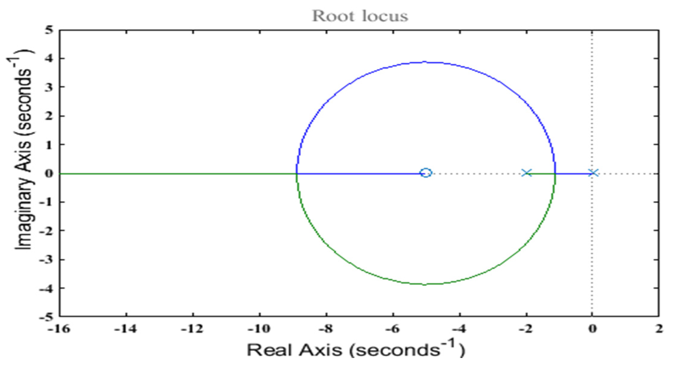
This is evident from (44) that the behavior of the closed loop may be altered with the criterion γ = 1 ( k I d c m q f * ) , which shows that the design of the controller has to be followed along a generalized root locus of the nonlinear system with changing criterion γ , so for steady-state operation, this complete anticipated performance scope of the PMSG system is achieved. Since m q f * is anticipated to stay in a calculated domain of values. The root locus evaluation gives a recognized significant range for the dominant pole of (44) that is to be related to the expected settling time T s . Moreover, during the expression of the parameter γ , a suitable value for the integral gain k I d c can be chosen, although the value of k P d c is resolved from (43), which provides the required settling time and the damping factor.

7. Angular Speed Operation Controller

Through P s r e f , it may be determined that for values under P m max P G S C g r i d , r e f , an external speed controller can be applied to obtain the angular speed. This method can be implemented using a PI controller as follows:
P s r e f = k P ω ω r + k I ω 0 1 ( ω r r e f ω r ) d τ
where ω r r e f = ω r o p t according to Equation (4) for the angular speed function. For evaluating its function, the initial two differential equations of (17) are accounted stable under VOC arrangement, providing the following:
λ q s * = R s ω s I d s *   and
λ d s * = V g r i d R s I q s * ω s
For PMSG of MW ratings, the stator resistance is estimated at the extent of (mΩ), although for 50 Hz utility grids ω s = 100 π rad/s. Consequently, the q-axis stator flux component has a value that is small in number, having a stable value; thus, the d-axis stator flux component supposes a fairly steady state value λ d s ¯ , shown as follows:
λ d s * λ d s ¯ = V g r i d ω s
Thus, near-stator-flux-oriented control is anticipated for the machine-side converter. Accordingly, by applying Equations (7), (12), (13), (18) and (47), the equation below-mentioned electromagnetic torque is achieved as follows:
T e = p ω s P s
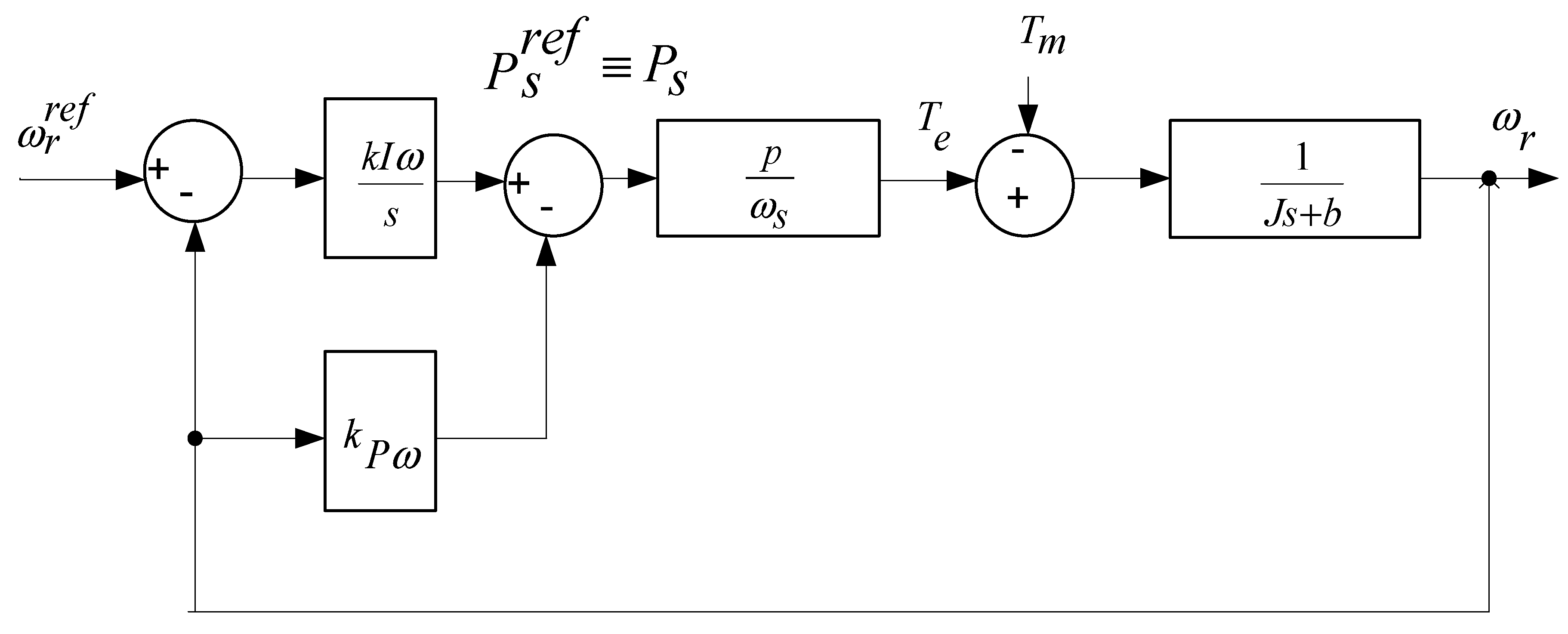
That is dependent directly on the stator active power. Adjusting the stator power controllers Equations (25) and (26) being quicker than the angular speed controller, considering P s = P s r e f utilizing the timescale division assumption. In view of only the slow dynamics of ω r from Equations (17) and (48), the block diagram in Figure 1, Figure 2 and Figure 3 derived analytically. Recognizing the mechanical torque T m as a disruption, the transfer function given below is obtained for the closed-loop system:
ω r ω r r e f = p J ω s k I ω S 2 + ( b J + p J ω s k P ω ) S + p J ω s k I ω
which can be written in the form of Equation (42) with ω n 2 = k l ω p / ( J ω s ) and 2 ζ ω n = [ b J + k p ω P / ( J ω s ) ] employing the 2% standard, angular speed controller gains are measured below:
k P ω = 8 T s b J J ω s p   and   k I ω = 16 T s 2 ζ 2 J ω s p
Using the phrase b J , the proportional gain is supposed to be negligible in large-scale wind energy conversion systems, which cannot be considered in the gain selection method. Moreover, J is a prominent variable of the system.
Concluding, it is observed that a new design method for DPC has been developed, which ensures stability while providing reliable simplifications to the structure of the controller and the comprehensive nonlinear implementation. As signified by the evaluation, only voltage alignment is needed on the GSC and MSC, which further make it simple the controller design. The whole system and controller configuration are illustrated in Figure 4.
The established feedback control function controls the stator current related to a PMSG and is also used to accommodate the actual values of the controller. The PMSG-wind energy conversion system can be linked with a compensation network and a power electronic converter. Figure 4a,b present the phase A fault current of the stator. A collection is observed regarding of stator current. The proposed model is validated by plotting a conventional model and employing it as a standard model. The proposed model is verified by utilizing simulation as represented in Figure 4a,b.

7.1. Short Circuit Current Behavior

The response of the PMSG under three-phase inherent faults is illustrated in Figure 5a,b. During this fault condition, the breaker is open when the crowbar protection circuit is activated. An increase in crowbar current indicates that the upper cut-off threshold has been reached due to the rise in DC-link voltage. Consequently, the MSC is disabled and remains non-operational for a brief period while the crowbar resistance is connected to the rotor circuit [22]. If the DC-link voltage drops below the lower threshold, the crowbar is deactivated and reconnected to the rotor circuit, allowing the system to resume normal operation. Transformer saturation occurs when the terminal voltage falls below the LVRT threshold, triggering the unit breaker to isolate the faulted system [23]. Figure 5c shows the impact of transformer saturation under three-phase permanent faults at the Point of Common Coupling (PCC). The figure presents a comparative analysis of terminal voltage behavior with and without the influence of transformer saturation, highlighting its effect on system voltage stability.

7.2. Crowbar Protection

A thyristor-based crowbar actuation circuit can be triggered using a gate signal, enabling it to enter conduction mode. Once activated, the crowbar remains conducting until the current through it is extinguished. In more advanced configurations, active crowbar circuits employ Insulated Gate Bipolar Transistors (IGBTs). Unlike thyristors, IGBTs can be turned off by reducing the gate-emitter voltage below the threshold level [24]. Although the passive and active crowbar schemes differ in their activation mechanisms, both manage extreme rotor currents through a bypass resistor. Crowbar activation can be controlled using DC bus, either voltage or rotor current measurements. To prevent excessive voltage on the converter terminals during faults, the bypass resistor must have a low value, although it does not need to be highly precise. Therefore, adjusting the bypass resistor value is necessary to meet the desired protection characteristics [25]. The passive crowbar configuration is illustrated in Figure 5a, while the operational differences between passive and active crowbar schemes during fault occurrence and recovery are shown in Figure 5d. A back-to-back converter that helps regulate stator current and voltage profiles supports the LVRT capability. The fault behavior of a PMSG under such conditions is depicted in Figure 5c. The short-circuit response of the PMSG varies depending on the type of crowbar circuit and the LVRT strategy employed. In some PMSG configurations, a chopper resistor is installed in the DC link capacitor as an alternative to a rotor-side crowbar circuit for dissipating fault energy.

7.3. Current Limiting During a Fault

To enhance performance in tracking and extracting maximum wind power and to maintain system stability under normal operating conditions, a structured controller design procedure is implemented [26]. This controller is responsible for improving overall system performance while ensuring stability. It also addresses the rejection of disturbances, uncertainties, and un-modeled dynamics [27]. In addition to the controller design, LVRT and start-up algorithms are incorporated to protect against faults or severe oscillations. Algorithms such as the active crowbar, series dynamic restorer, and dynamic voltage restorer are considered effective options for implementing LVRT functionality. During normal operating conditions, these protection algorithms function independently of the main control approach. This independence makes them suitable for integration with the proposed power transfer matrix method. A feedback loop is included in the system to monitor converter currents and to reduce power reference commands during oscillatory conditions. This loop works in conjunction with LVRT algorithms to mitigate overcurrent scenarios during transients. Importantly, the feedback loop operates without compromising controller performance under normal conditions and is thus an integral part of the controller design.

8. System Performance Evaluation—Results

This section presents a comprehensive evaluation of the proposed system and the controller’s performance, using results obtained from real-time data. Table 1 summarizes the specifications of the 1.5-MW PMSG system.
The recommended method of the nonlinear dynamic model to verify the efficiency of the simulation results has been performed. At first, the performance of the dynamic system was validated using small changes in real power.
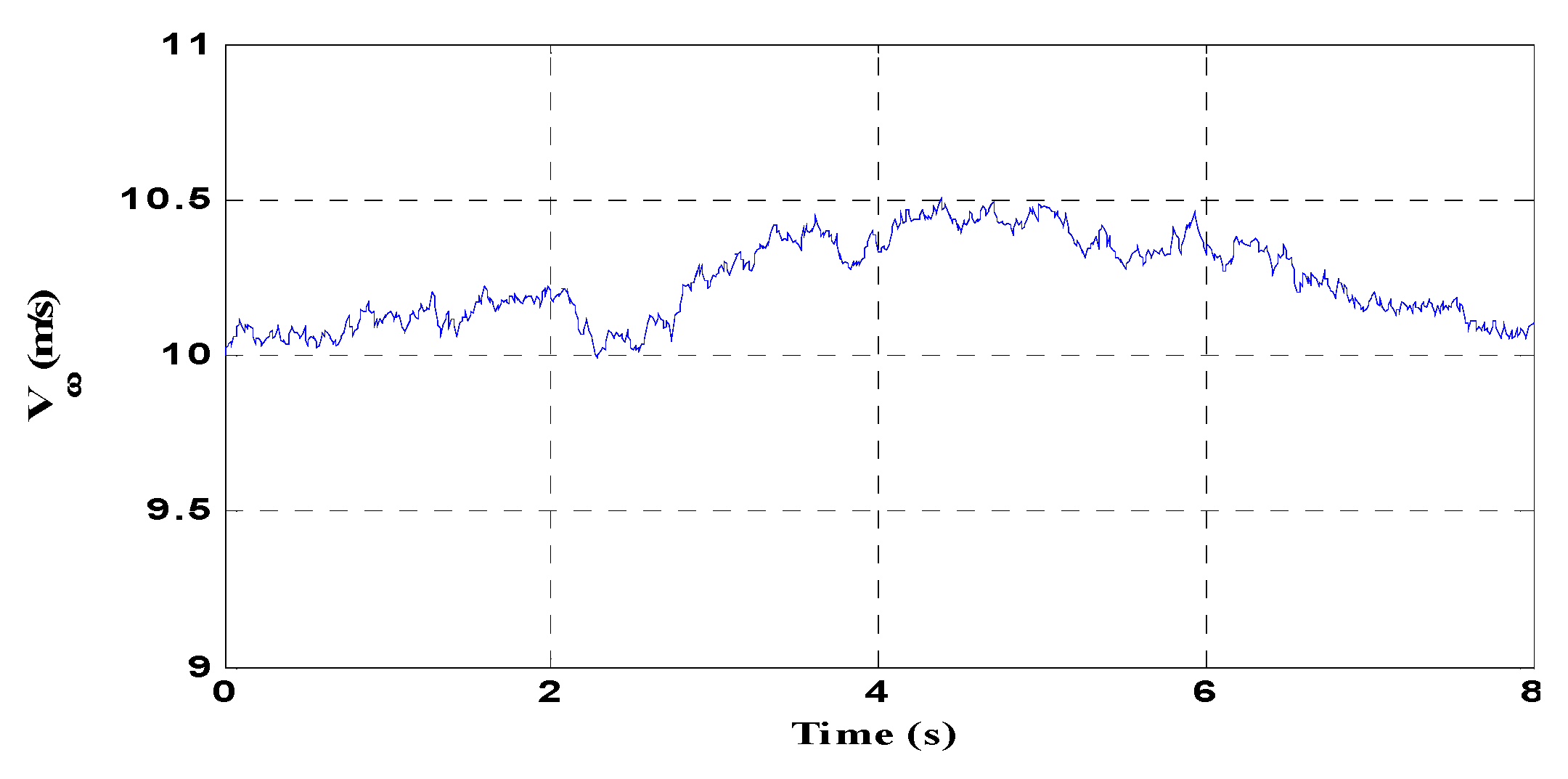
The gains of power are specified in Table 2. Furthermore, Table 2 holds the gain of PI controller operation, which was measured for T s = 2.6   s and ζ = 0.707 , for the speed of wind response of the system is simulated by the feedback control in Figure 6, which is based on real information.
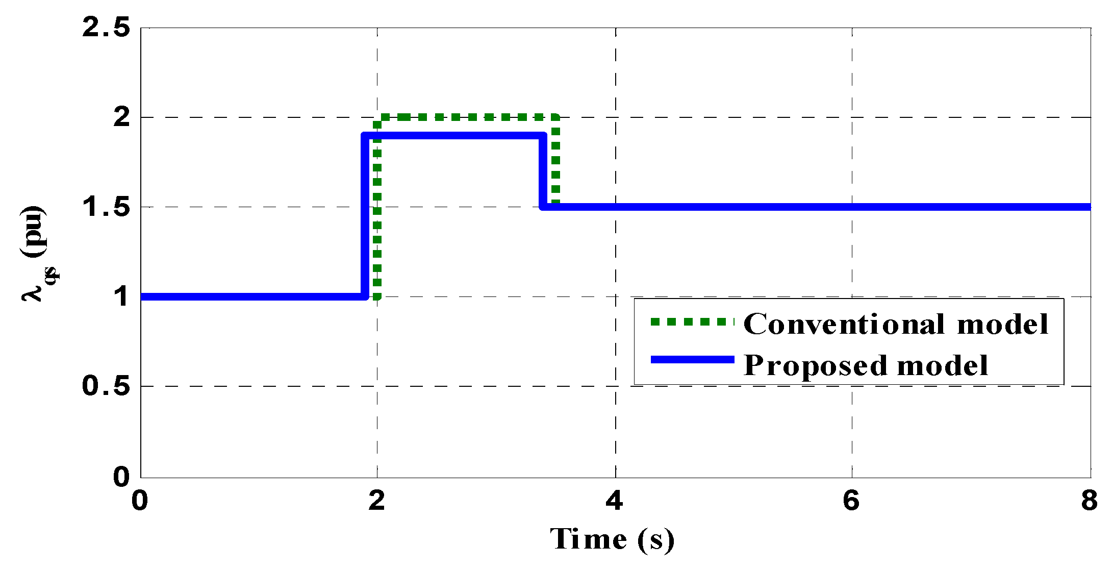
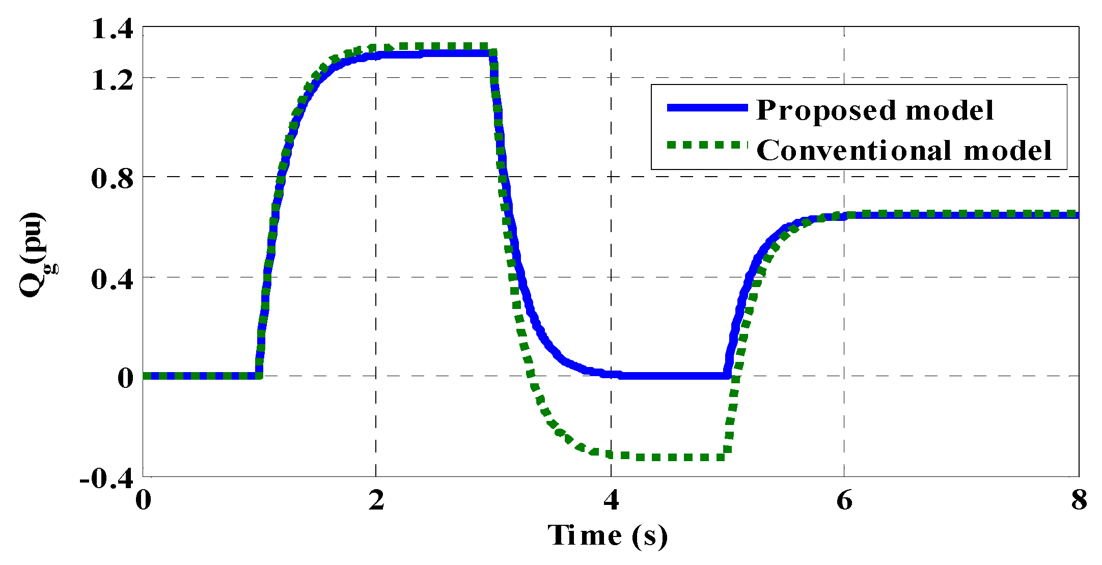
Adjustments regarding references of reactive power for both the stator and the GSC are being examined. Specifically, the combination of active and reactive power references is initially established at zero. All along 3   s , the stator reactive power reference Q s gets 0.2 pu and at time instant 3   s , that supposes valuation at −0.1 pu. Alternatively, the reactive power is exchanged between the GSC and the grid Q g becomes 0.2.5 pu, at that time 2.5 s, and −0.01 pu at that time 4 s. Additionally, Figure 7 and Figure 8 illustrate the feedback of the stator flux elements. The assumptions made regarding the stator flux components regarding speed control of the rotor apply to the studied operations, although a near stator-flux orientation has been successfully attained. It is clear from Equation (35) that the stator power expression in Equation (29) concerning the closed-loop control system, λ d s is connected directly with P s and λ q s is connected directly with Q s , which can also be verified by inspecting Figure 7 and Figure 8.
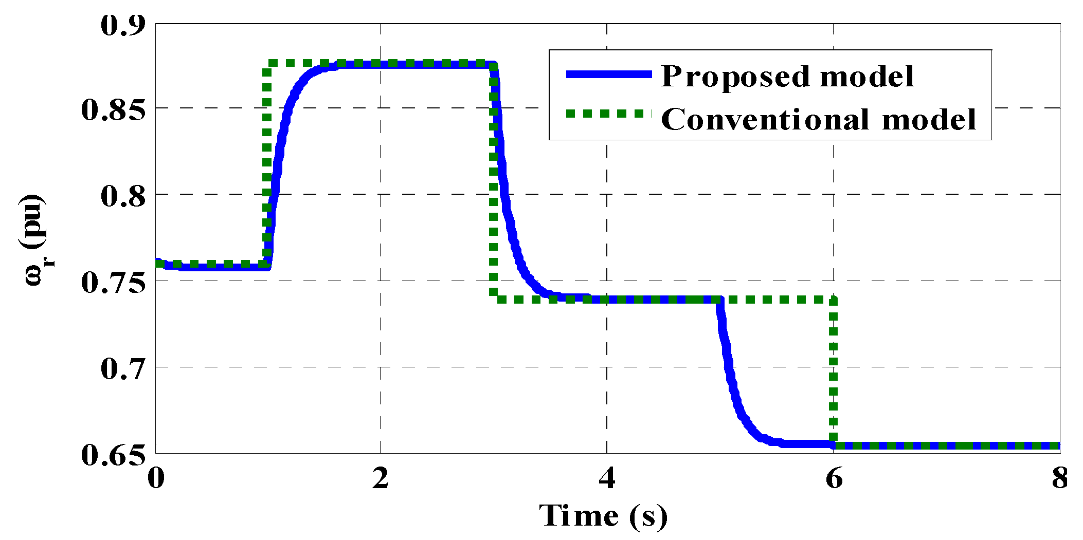
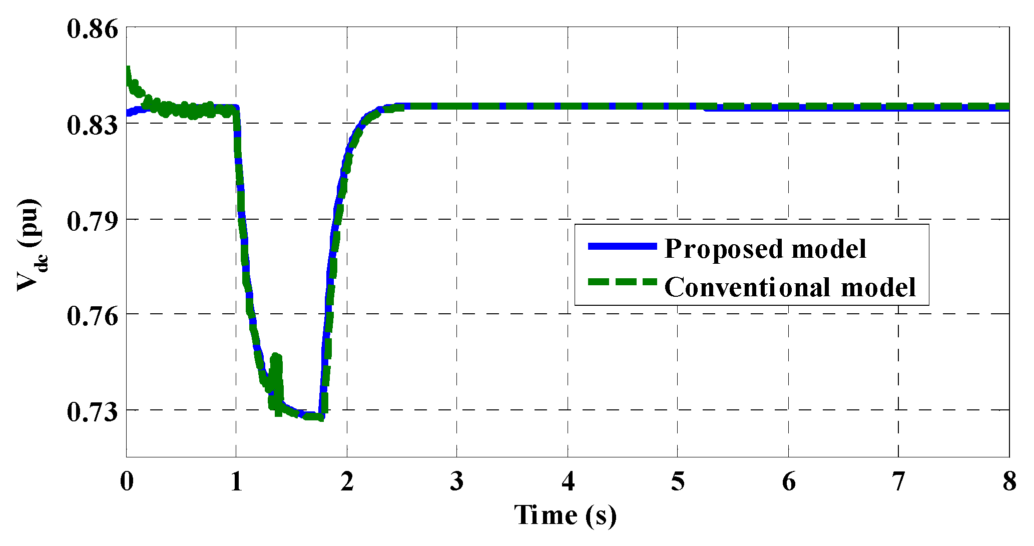
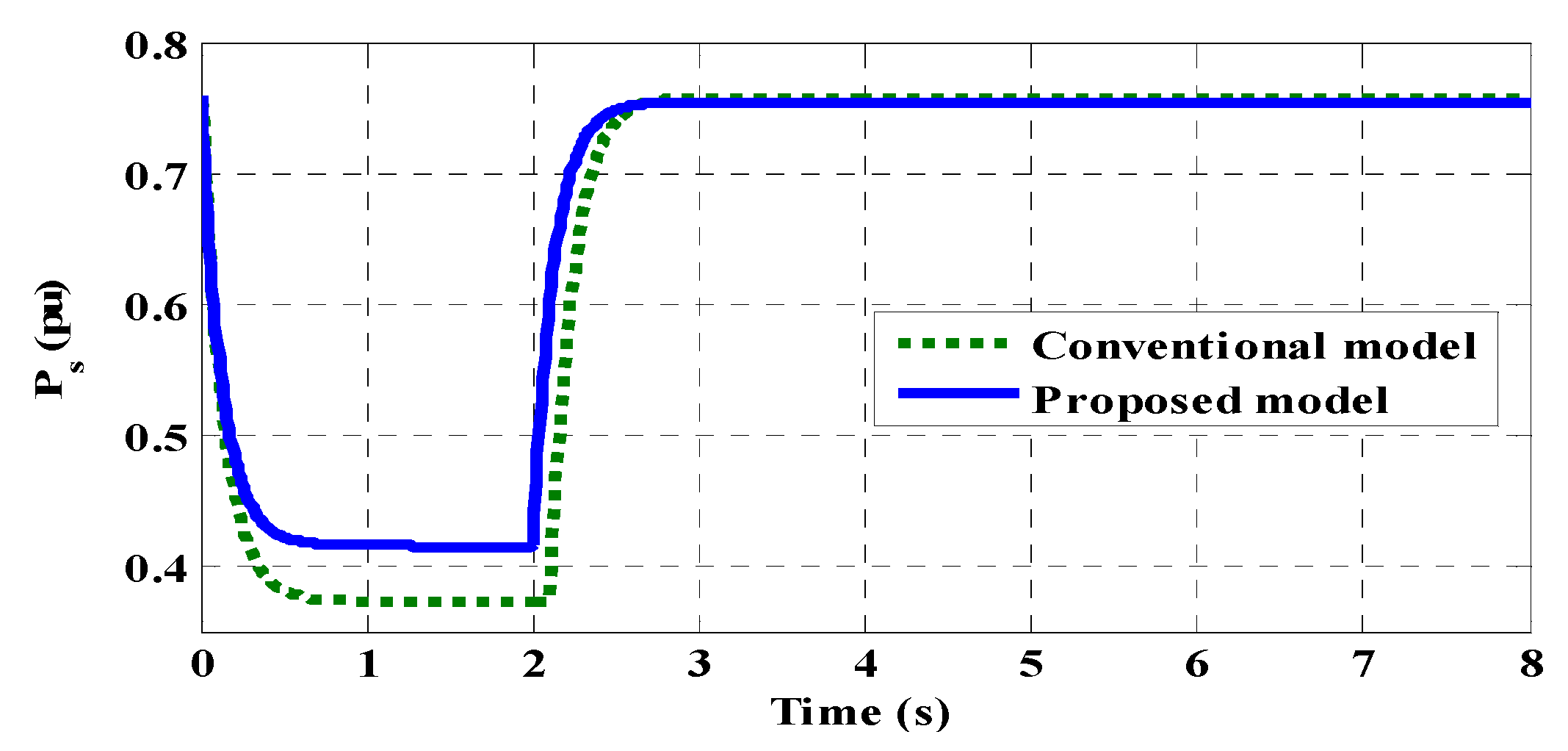
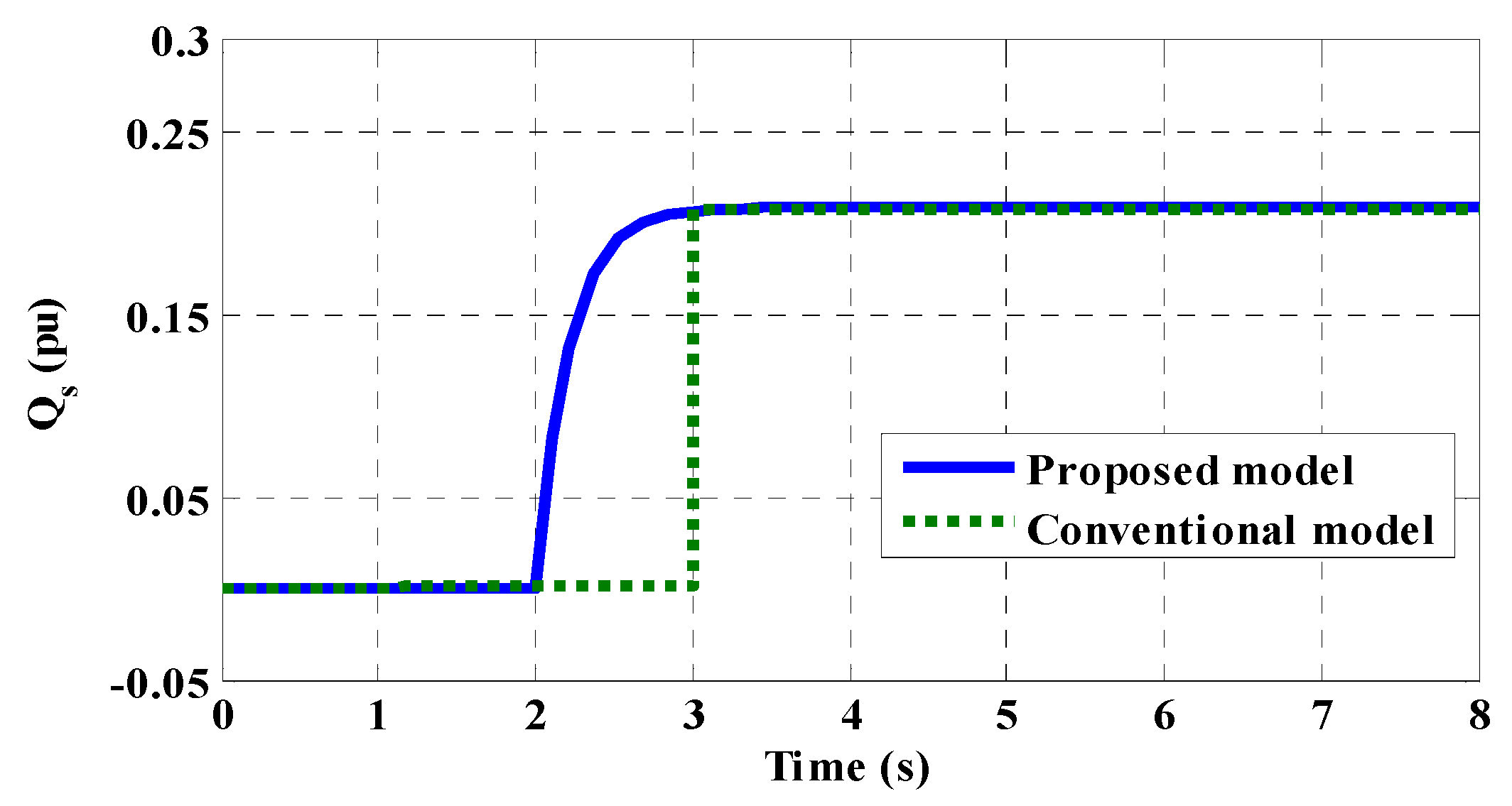
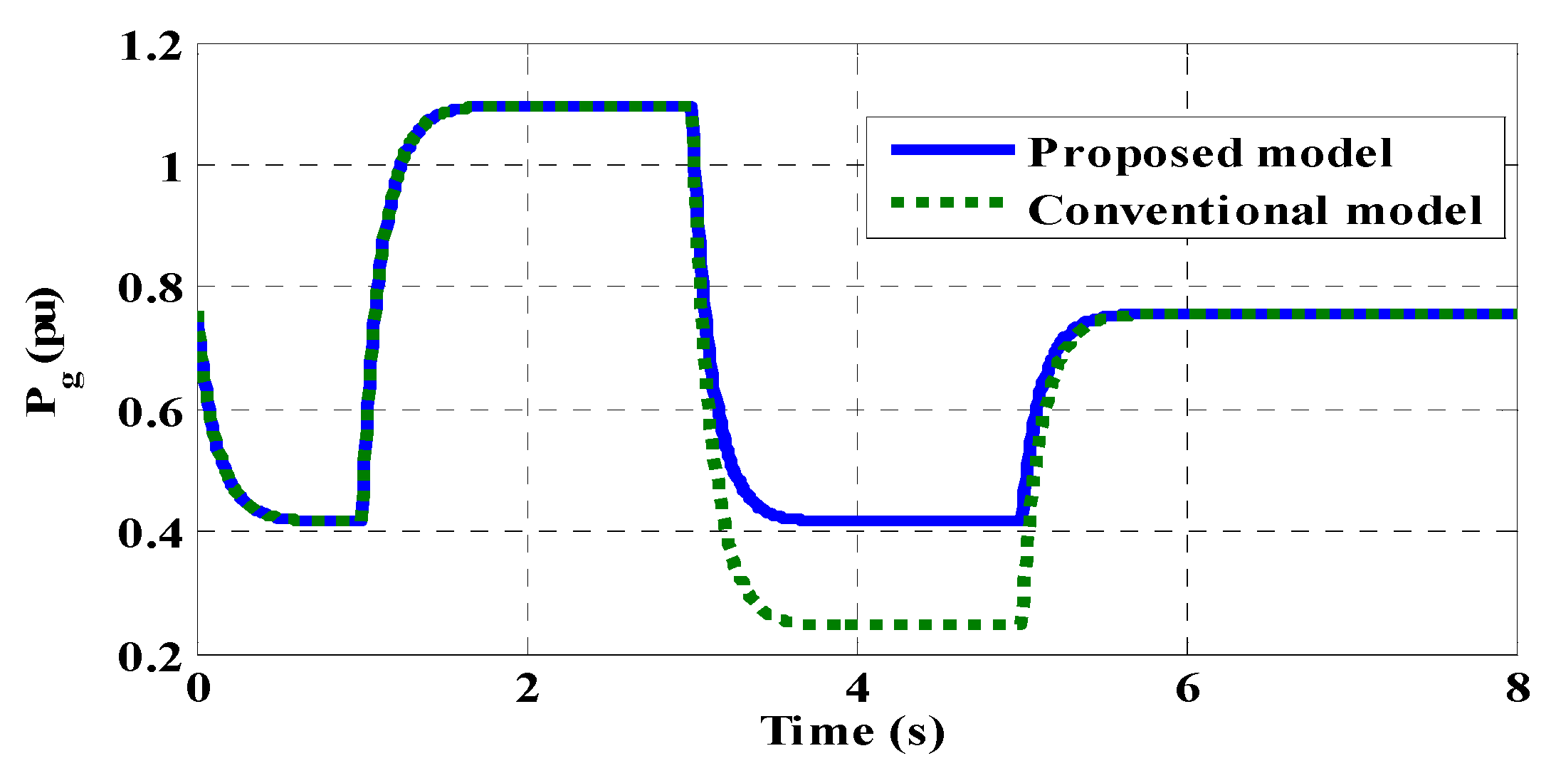
In Figure 9, the optimal speed of rotor reference, alongside the response of the angular speed, is presented. The stable transient reaction is revealed by observations that align with the rotor’s speed controller design and arrangement. In Figure 10, illustrates the DC link voltage attained between the MSC and grid sides. In the case of conventional controller , a noticeable peak value occurs at 1.3 s as compared to the proposed controller suppresses successfully. In Figure 11, the GSC, total PMSG active power, and stator responses are given. A consistent result appears to be achieved with minor overshoots, and the negative value signifies an insertion into the grid. Figure 12 shows the reactive power responses for the GSC, the stator, and the total PMSG. A rapid transient is noted without any fluctuations. Despite the lack of decoupling terms in all the controllers, the variations in reactive power have a minimal effect on the dynamics of active power. The GSC reactive power, as well as the stator, is immediately found within less than 1 s. As a reference to the change, however, the reactive power dynamics are disturbed slightly by the changes in active power. Ultimately, Figure 13 and Figure 14 illustrate the results across all ratios of duty that are constrained and take on values reflecting the linear functioning of both converters.
At every instance, the response of the system stabilizes at equilibrium after a brief transient period, thereby fully confirming the stability analysis.
In Figure 15, the generalized root locus is given. The high negative value is at −5 Hz. The arrows show the movement of the poles.
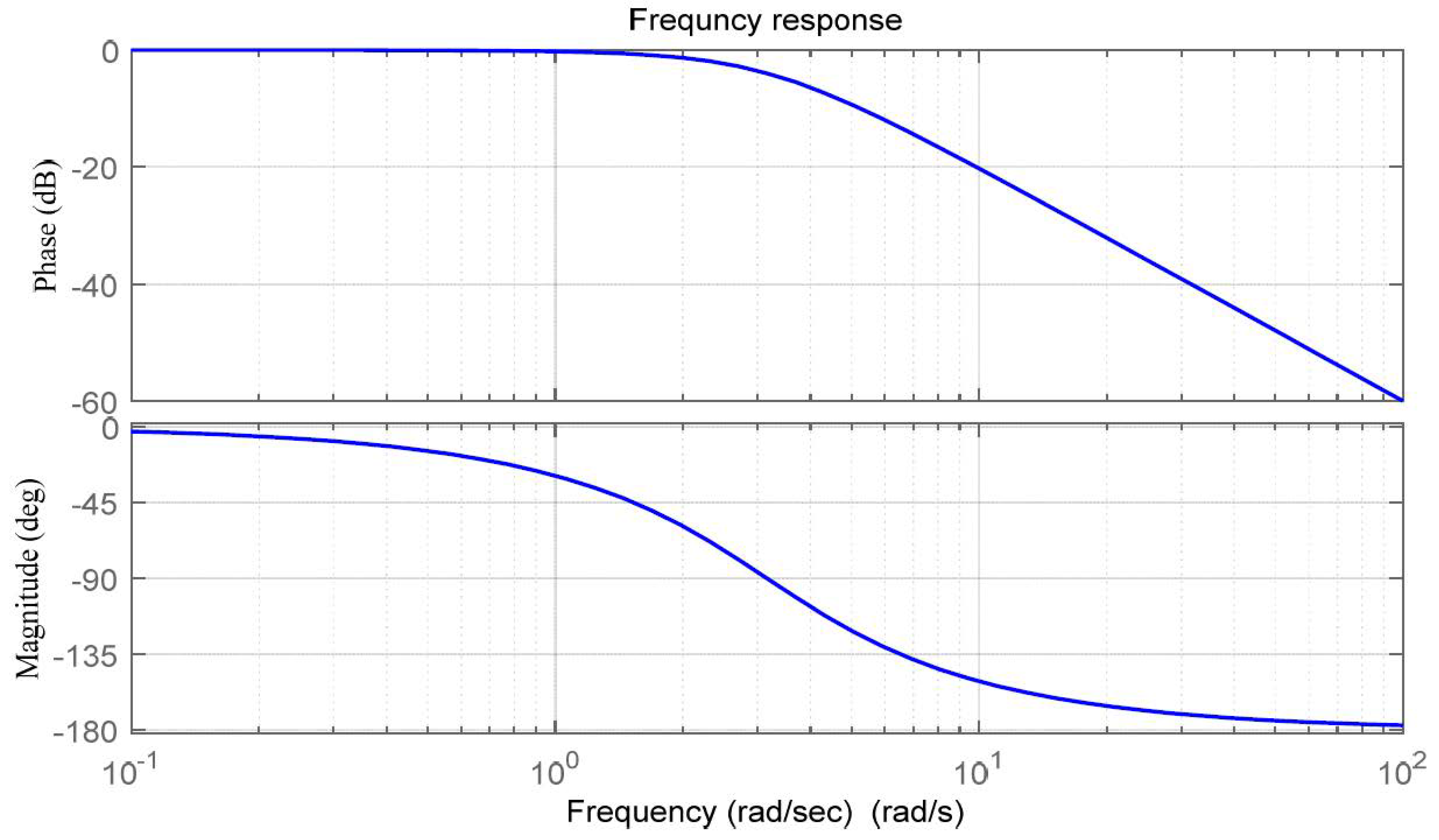
Figure 16 The frequency response curve is shown. Frequency response shows magnitude (top), phase (bottom), shows frequency response with respect to magnitude and phase.

9. Conclusions

In this paper, the LVRT capability of PMSGs is focused on by limiting stator current oscillations and stabilizing the DC-link voltage during voltage dips. The proposed control technique improves the transient response of the PMSG under fault conditions. Specifically, the paper investigates real/reactive power control using a PI controller, with system reliability enhanced through the Lyapunov stability method. Simulation results demonstrate that the proposed nonlinear control scheme effectively increases real power output and reduces current oscillations. The advanced Lyapunov-based stability analysis ensures the DC-link voltage remains stable and the rotor speed is maintained for maximum power extraction, even under disturbances caused by variations in real and reactive power references.

10. Future Work and Discussion

Although the Permanent Magnet Synchronous Generator (PMSG) WTs have proven to be an effective and reliable solution for WECS, there are still several areas that can be further investigated for systems, reliability, and efficiency under dynamic WTS and power grid environments. However, some of the recommended future directions include the following:
(1)
Fuzzy Logic Control (FLC): These types of controllers can be applied to grip the nonlinear and uncertain behavior of WTs, and it does not require any accurate mathematical model.
(2)
Neural Network (NN) Controller: the NN controller is a well-known controller for many applications, such as solar/wind and other renewable sources, and it can also provide self-learning and pattern recognition that can enhance PMSG performance under variable wind profiles. However, the research could discover the use of AI, machine and deep learning architectures for predictive control, system identification, and adaptive optimization in order to maintain the wind turbine systems’ stability and performance.
(3)
Model Predictive Control (MPC): These types of controllers can be used to handle various system variables with limitations, making them highly suitable for grid-connected WTs. In PMSG systems, MPCs have the ability to optimize maximum energy at minimum wind speed, and they can also minimize the system’s losses and deliver smooth power during grid disturbances.
(4)
Hybrid Intelligent Control Systems: A combination of fuzzy logic, neural networks, MPC, and AI could be integrated to create hybrid controllers that exploit the strengths of each approach. For instance, fuzzy logic can provide robustness, while neural networks add adaptability, and MPC ensures optimal control under constraints. Such hybrid schemes may offer superior performance in terms of efficiency, reliability, and resilience.

Author Contributions

Conceptualization, M.A.B. and G.S.K.; methodology, M.A.B. and R.A.T.; software, G.S.K. and M.A.B.; validation, M.A.B.; formal analysis, investigation, M.A.B. and G.S.K.; data curation, M.A.B.; writing—original draft, M.A.B.; writing—review and editing M.B., M.I.M., and T.A.J.; supervision, G.S.K.; funding acquisition M.I.M. and M.A. All authors have read and agreed to the published version of the manuscript.

Funding

This research received no external funding.

Data Availability Statement

The data presented in this study are available on request from the corresponding author.

Conflicts of Interest

The authors declare no conflicts of interest.

Abbreviations

CpPower coefficient of wind turbine
RsResistance of stator
Idsd-axis Stator current
Iqsq-axis Stator current
RrResistance of Rotor
Idrd-axis Rotor current
Iqrq-axis Rotor current

Appendix A

a 1 = R s σ L s L r
a 2 = R r L m σ L s L r
a 3 = p ω r L m σ L s
b 1 = R s L r + R r L s
b 2 = L m V g
b 3 = R f L f
b 4 = V g L f
b 5 = b L r V g 2 ω r 2

References

  1. Baloch, M.H.; Wang, J.; Kaloi, G.S. Stability and nonlinear controller analysis of wind energy conversion system with random wind speed. Int. J. Electr. Power Energy Syst. 2016, 79, 75–83. [Google Scholar] [CrossRef]
  2. Nguyen, P.T.H.; Stüdli, S.; Braslavsky, J.H.; Middleton, R.H. Coordinated Control for Low Voltage Ride Through in PMSG Wind Turbines. IFAC-PapersOnLine 2018, 51, 672–677. [Google Scholar] [CrossRef]
  3. Polinder, H.; Ferreira, J.A.; Jensen, B.B.; Abrahamsen, A.B.; Atallah, K.; McMahon, R.A. Trends in Wind Turbine Generator Systems. IEEE J. Emerg. Sel. Top. Power Electron. 2013, 1, 174–185. [Google Scholar] [CrossRef]
  4. Mayilsamy, G.; Lee, S.R.; Joo, Y.H. An improved model predictive control of back-to-back three-level NPC converters with virtual space vectors for high power PMSG-based wind energy conversion systems. ISA Trans. 2023, 143, 503–524. [Google Scholar] [CrossRef] [PubMed]
  5. Shotorbani, A.M.; Mohammadi-Ivatloo, B.; Wang, L.; Marzband, M.; Sabahi, M. Application of finite-time control Lyapunov function in low-power PMSG wind energy conversion systems for sensorless MPPT. Int. J. Electr. Power Energy Syst. 2019, 106, 169–182. [Google Scholar] [CrossRef]
  6. Ghafoor, A.; Apsley, J.; Al Kez, D.; Djurović, S. Operation of a wind turbine permanent magnet synchronous generator (PMSG) for ancillary frequency support services. Int. J. Electr. Power Energy Syst. 2025, 167, 110623. [Google Scholar] [CrossRef]
  7. Wang, C.-N.; Lin, W.-C.; Le, X.-K. Modelling of a PMSG Wind Turbine with Autonomous Control. Math. Probl. Eng. 2014, 2014, 856173. [Google Scholar] [CrossRef]
  8. Huang, S.; Wang, J.; Huang, C.; Zhou, L.; Xiong, L.; Liu, J.; Li, P. A fixed-time fractional-order sliding mode control strategy for power quality enhancement of PMSG wind turbine. Int. J. Electr. Power Energy Syst. 2022, 134, 107354. [Google Scholar] [CrossRef]
  9. Kuppusamy, S.; Joo, Y.H. Stabilization of PMSG-based wind turbine systems with sampling information: Dynamic delay partition method. Int. J. Electr. Power Energy Syst. 2023, 149, 109023. [Google Scholar] [CrossRef]
  10. Ibrahim, R.A.; Zakzouk, N.E. A PMSG Wind Energy System Featuring Low-Voltage Ride-through via Mode-Shift Control. Appl. Sci. 2022, 12, 964. [Google Scholar] [CrossRef]
  11. Hu, Y.-L.; Wu, Y.-K.; Chen, C.-K.; Wang, C.-H.; Chen, W.-T.; Cho, L.-I. A Review of the Low-Voltage Ride-Through Capability of Wind Power Generators. Energy Procedia 2017, 141, 378–382. [Google Scholar] [CrossRef]
  12. Mallick, P.; Sharma, R.; Kabat, S.R. Low Voltage Ride Through Improvement Using Power System Stabilizer for DFIG based Wind Energy Conversion System. In Proceedings of the 2022 2nd Odisha International Conference on Electrical Power Engineering, Communication and Computing Technology (ODICON), 11–12 November 2022; IEEE: Piscataway, NJ, USA, 2022; pp. 1–6. [Google Scholar] [CrossRef]
  13. Emeghara, C.M.; Mahajan, S.M.; Arzani, A. Direct Power Control of a Surface-Mounted Permanent Magnet Synchronous Generator Wind Turbine for Offshore Applications. IEEE Access 2023, 11, 62409–62423. [Google Scholar] [CrossRef]
  14. Shanmugam, L.; Joo, Y.H. Stabilization of permanent magnet synchronous generator-based wind turbine system via fuzzy-based sampled-data control approach. Inf. Sci. 2021, 559, 270–285. [Google Scholar] [CrossRef]
  15. Abo-Khalil, A.G.; Alobaid, M. Optimized Control for PMSG Wind Turbine Systems under Unbalanced and Distorted Grid Voltage Scenarios. Sustainability 2023, 15, 9552. [Google Scholar] [CrossRef]
  16. Soliman, M.A.; Hasanien, H.M.; Al-Durra, A.; Alsaidan, I. A Novel Adaptive Control Method for Performance Enhancement of Grid-Connected Variable-Speed Wind Generators. IEEE Access 2020, 8, 82617–82629. [Google Scholar] [CrossRef]
  17. Han, S.; Yao, D.; Wei, W. Mechanical Power Calculation of Wind Turbine in Mountainous Wind Farm Model Utilizing Variation Coefficient of Wind Speed. In Proceedings of the 2019 IEEE Sustainable Power and Energy Conference (iSPEC), 21–23 November 2019; IEEE: Piscataway, NJ, USA, 2019; pp. 325–330. [Google Scholar] [CrossRef]
  18. Hawkins, N.; McIntyre, M.L. A Robust Nonlinear Controller for PMSG Wind Turbines. Energies 2021, 14, 954. [Google Scholar] [CrossRef]
  19. Ramasamy, T.; Basheer, A.A.; Tak, M.-H.; Joo, Y.-H.; Lee, S.-R. An Effective DC-Link Voltage Control Strategy for Grid-Connected PMVG-Based Wind Energy Conversion System. Energies 2022, 15, 2931. [Google Scholar] [CrossRef]
  20. Hu, Q.; Xiong, Y.; Liu, C.; Wang, G.; Ma, Y. Transient Stability Analysis of Direct Drive Wind Turbine in DC-Link Voltage Control Timescale during Grid Fault. Processes 2022, 10, 774. [Google Scholar] [CrossRef]
  21. Yessef, M.; Bossoufi, B.; Taoussi, M.; Motahhir, S.; Lagrioui, A.; Chojaa, H.; Lee, S.; Kang, B.-G.; Abouhawwash, M. Improving the Maximum Power Extraction from Wind Turbines Using a Second-Generation CRONE Controller. Energies 2022, 15, 3644. [Google Scholar] [CrossRef]
  22. Gholizadeh, M.; Tohidi, S.; Oraee, A.; Oraee, H. Appropriate crowbar protection for improvement of brushless DFIG LVRT during asymmetrical voltage dips. Int. J. Electr. Power Energy Syst. 2018, 95, 1–10. [Google Scholar] [CrossRef]
  23. Yin, J.; Huang, X.; Qian, W. Analysis and research on short-circuit current characteristics and grid access faults of wind farms with multi-type fans. Energy Rep. 2024, 11, 1161–1170. [Google Scholar] [CrossRef]
  24. Liu, D.; Ma, X.; Wang, Z.; Yang, Y.; Wang, J.; Zhou, L. Crowbar-Less Low-Voltage Ride-Through Control Strategy for Full-Size Converter-Based Variable-Speed Pumped Storage Units in Generation Mode. Electronics 2025, 14, 1411. [Google Scholar] [CrossRef]
  25. Huy, T.N.; Le Hanh, D.; Takano, H.; Duc, T.N. Cooperative LVRT control for protecting PMSG-based WTGs using battery energy storage system. Energy Rep. 2023, 9, 590–598. [Google Scholar] [CrossRef]
  26. Mahela, O.P.; Gupta, N.; Khosravy, M.; Patel, N. Comprehensive Overview of Low Voltage Ride Through Methods of Grid Integrated Wind Generator. IEEE Access 2019, 7, 99299–99326. [Google Scholar] [CrossRef]
  27. Li, J.; Qiu, Q.; Zhan, M. An Improved Crowbar Control Circuit of DFIG during LVRT. In Proceedings of the 2021 IEEE 4th International Electrical and Energy Conference (CIEEC), 28–30 May 2021; IEEE: Piscataway, NJ, USA, 2021; pp. 1–6. [Google Scholar] [CrossRef]
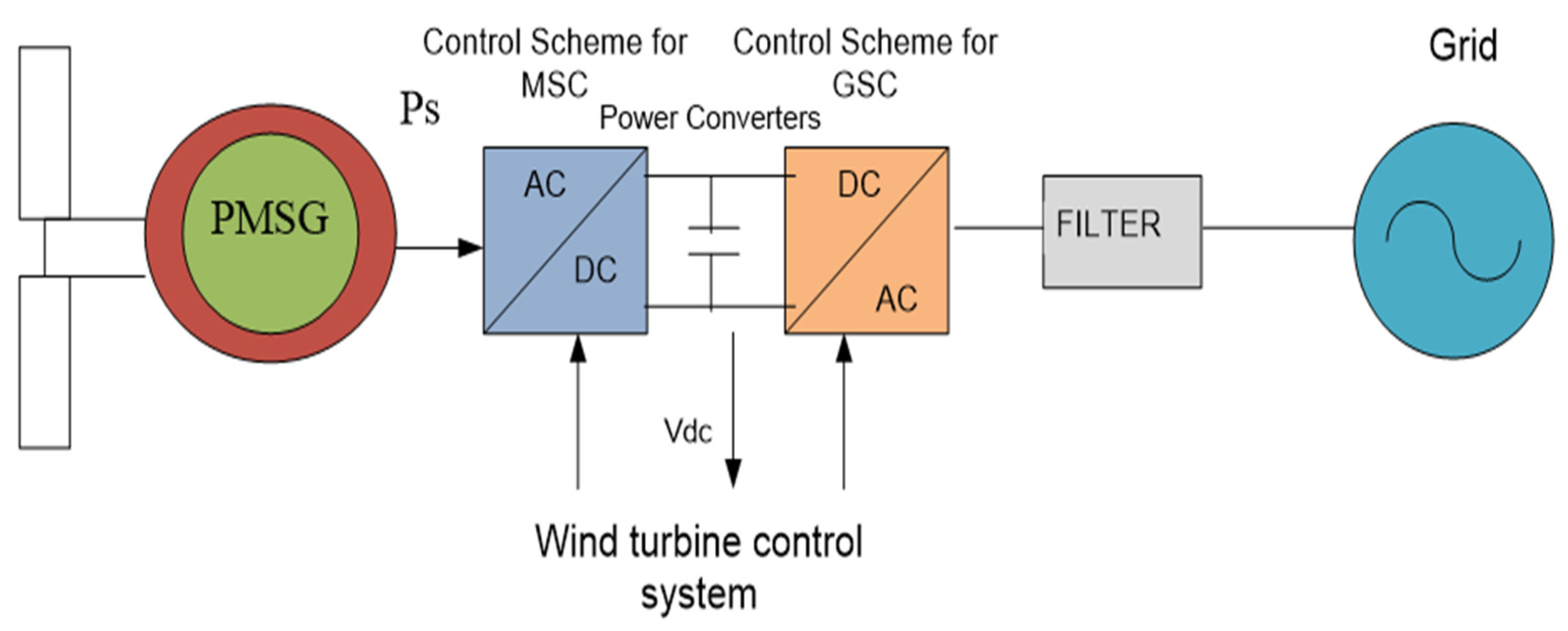
Figure 1. PMSG-based WECS.
Machines 13 00886 g001
Figure 2. Schematic diagram of the rotor dynamics and the proposed angular speed.
Machines 13 00886 g002
Figure 3. Control variables for MSC and GSC.
Machines 13 00886 g003
Figure 4. (a) Stator Symmetrical fault current. (b) Enlarged outlook of the stator fault current controller.
Machines 13 00886 g004
Figure 5. (a) Current in the stator at the time of a three-phase fault. (b) Voltage in the stator during a 3-phase fault occurs. (c) Saturation effect of the transformer on the terminal voltage while a fault occurs. (d) DC-link voltage behavior during a fault situation is brought into an asymptotically stable position at a natural, uncertain wind speed.
Machines 13 00886 g005
Figure 6. Variation in wind speed versus time.
Machines 13 00886 g006
Figure 7. Stator flux λ q s (pu) vs. time (s).
Machines 13 00886 g007
Figure 8. Stator flux λ d s (pu) vs. time (s).
Machines 13 00886 g008
Figure 9. Rotor speed ω r (pu) vs. time.
Machines 13 00886 g009
Figure 10. DC link voltage V d c (pu) vs. time.
Machines 13 00886 g010
Figure 11. Active power of the stator P s (pu) vs. time.
Machines 13 00886 g011
Figure 12. Reaction of the stator Q s (pu) vs. time.
Machines 13 00886 g012
Figure 13. Active power of the grid P g (pu) vs. time.
Machines 13 00886 g013
Figure 14. Reactive power of the grid Q g (pu) vs. time.
Machines 13 00886 g014
Figure 15. Root locus for dc-link.
Machines 13 00886 g015
Figure 16. Frequency response.
Machines 13 00886 g016
Table 1. PMSG wind energy system parameters.
SymbolQuantityValue
RsResistance (stator)0.01 Ω
RrResistance (rotor)0.00840 Ω
LsInductance (stator)0.005310 H
LrInductance (rotor)0.0053135 H
LmMutual inductance0.0051836 H
PNo. of pairs poles3.2
RfResistance of grid filter0.03 Ω
LfInductance of grid0.002 H
CCapacitance (DC-link)0.02 F
RTBlade radius36 m
BCoefficient of rotor0.00016 Nm s/rad
JTotal rotor inertia765.5 kg.m2
NgRatio of gearbox62.1
ΒPitch angle
ΡAir density1.2 kg/m3
λoptTip–speed ratio optimal 6.323
ωsAngular frequency grid2 π f rad/s
VgVoltage grid575 V rms
Table 2. Gains of the controller.
GainValueGainValueGainValue
kPPr0.001kPPf0.01kPω32,100
kIPr0.001kIPf0.1kIω6400
kPQr0.001kPQf0.001kPdc10,000
kIQr0.01kIQf0.01kIdc4000
Disclaimer/Publisher’s Note: The statements, opinions and data contained in all publications are solely those of the individual author(s) and contributor(s) and not of MDPI and/or the editor(s). MDPI and/or the editor(s) disclaim responsibility for any injury to people or property resulting from any ideas, methods, instructions or products referred to in the content.