Abstract
Electromagnetic separators are widely used in new energy battery purification, resource recycling, and mineral processing. However, coil heating can cause a decline in separation performance and damage to coil insulation. To ensure the stable operation of electromagnetic separators, cooling plates are employed to effectively mitigate temperature rise. To explore a high-performance and economical cooling method, this paper employs CFD finite element analysis for the structural optimization of cooling plates. First, the paper investigates the flow heat characteristics of S-shaped cooling plates. Numerical simulations are performed to analyze the variation of fluid characteristics with different numbers of water channels. Regression equations linking structural parameters to performance indicators are derived, and the optimal channel number and hydraulic diameter are determined. Furthermore, to enhance heat transfer efficiency, an innovative semicircular groove structure is introduced on the cooling plate walls. An optimization strategy based on a genetic algorithm is developed to determine the optimal groove parameters. A simulation shows that the optimized cooling plate reduces coil temperature by 12.63 °C with a decrease of 15.31% compared with the original design. Finally, a prototype with optimized parameters is manufactured after the experimental results of the two test points and the simulation results reveal errors of 0.26% and 0.96%, respectively. The experimental results align well with the simulations, confirming the reliability of the experimental results and the feasibility of the optimization strategy, and providing a reference for future cooling plate designs.
1. Introduction
Ferromagnetic material separation equipment is an important device in fields such as battery manufacturing, resource recycling, and mineral separation. The performance of its core component, the electromagnetic coil, directly determines the separation efficiency. However, electromagnetic coils generate a large amount of heat during operation. Due to poor air circulation inside the equipment and inadequate heat dissipation conditions, the coil temperature rises excessively. This temperature rise not only significantly reduces the operating magnetic field strength, affecting the separation effect, but also impairs the physical properties of the coil materials, thereby damaging the interlayer insulation structure, shortening the service life of the coil, and in severe cases, may even lead to coil burnout accidents [1,2]. To address this issue, some scholars have proposed a solution using high-temperature superconducting high-intensity magnetic separators, which achieve effective heat dissipation through low-temperature liquid nitrogen cooling technology [3,4]. Nevertheless, the high equipment cost of this cooling method limits its wide application in actual production. Therefore, developing an economical and efficient heat dissipation scheme remains an important research direction in the field of ferromagnetic material separation equipment.
To ensure efficient heat dissipation of the coil and maintain stable operation of the electromagnetic separator, the performance of heat exchange equipment is of crucial importance. As a commonly used heat exchange carrier in equipment, cooling plates are widely applied in the field of heat exchange, and rationality of their structural design serves as a key prerequisite for ensuring that heat dissipation performance meets the required standards. Experts and scholars have conducted extensive research on the structural optimization of cooling plates, with their core focus being the impact of channel structure design on heat exchange performance. Optimizing the flow channel topology can effectively alter fluid flow, thereby improving heat dissipation efficiency. Chen et al. [5] carried out a numerical study on parallel microchannel cold plates (PMCPs) and compared the performance of I-type, Z-type, and U-type configurations. Among these three systems, the performance of symmetric PMCP I and Z is similar and superior to that of symmetric PMCP U. Compared with simple parallel flow paths, serpentine cooling channels still demonstrate a relatively better cooling performance—they not only extend the flow distance of the cooling medium but also enhances fluid mixing, thereby improving the heat exchange efficiency of the cooling plate [6,7]. Raza et al. [7] conducted a numerical study on serpentine cooling channels, and the results indicated that serpentine channels exhibit better thermal performance in comparison to simple parallel channels. Similarly, Masaeli et al. [8] performed three-dimensional two-phase flow field numerical simulations on the fuel cell performance with four types of flow channels (parallel serpentine, serpentine baffle, serpentine interdigitated, and serpentine stepped). Compared with the parallel serpentine configuration, the geometries of serpentine baffle, serpentine interdigitated, and serpentine stepped flow channels showed a significant improvement in performance. Siddiqui et al. [9] established a comprehensive multi-physics model of serpentine-cooled photovoltaic modules and found that cooling plates with a V-shaped structure have significantly better flux uniformity and a higher power output. The thermal performance of streamlined cooling plates can be effectively enhanced by adopting new channel configurations [10]. Yogeshwar et al. [11] proposed a double serpentine channel cooling plate (DSC-CP) and applied it to battery thermal management systems (TMSs); compared with traditional single serpentine cooling plates, DSC-CP offers better temperature uniformity. The goal of their research was to optimize heat dissipation capacity while achieving energy efficiency [12,13]. Although the heat exchange performance of serpentine cooling plates is superior to that of traditional cooling plates, issues such as a thick boundary layer, poor heat exchange uniformity, and high pressure-drop result in poor economic efficiency within the cooling plates [14]. In response to this, Gao et al. [15] proposed gradually varied circular notched fins (GV-CNFs). Compared with the traditional serpentine channel cooling structure, GV-CNFs reduce the maximum temperature while controlling the pressure loss within a reasonable range. Grooves on the fluid surface can disrupt the development of the boundary layer, promote fluid mixing and heat exchange, and enhance heat transfer effects. The use of roughness elements can change the turbulent structure near the wall, reduce the thickness of the temperature boundary layer, and effectively improve heat exchange efficiency [16]. Liu et al. [17] pointed out that integrating cross channels into traditional serpentine channels can significantly reduce the required pump power and improve thermal performance under a certain power cost. Fan et al. [18] added one-way secondary channels and grooves to traditional serpentine cooling plates; compared with traditional cooling plates, their thermal performance decreased slightly, but the pump power consumption was reduced by 92.6% compared with the original cold plate. The adoption of appropriately configured structured surface roughness can improve the cooling and heat dissipation efficiency of cooling plates [19]. Gorzin et al. [20] conducted an experimental investigation into the heat transfer and fluid flow characteristics of ribbed serpentine microchannel heat sinks with different rib spacings. It was found that increasing the rib spacing effectively enhances the heat dissipation performance of the heat sink. Yang et al. [21] proposed a vein fractal structure liquid cooling plate, using the traditional serpentine liquid cooling plate as the control group, and focused on analyzing the limitations of serpentine channels in the thermal management of power batteries. Guo et al. [22] added multiple short rib groove guide vanes in the cooling channels, and the results showed that these guide vanes can effectively improve heat transfer efficiency. Yu et al. [23] altered the thermal boundary layer by adding grooves; experiments showed that the average temperature of photovoltaic thermal modules with periodically expanded grooves in the channels was significantly lower than that in smooth channels. The optimization of cooling plate structures often involves multiple parameters and indicators, and the impact of multiple parameters on performance indicators is usually difficult to predict. Traditional optimization methods often consume a great deal of time, so appropriate methods are needed to quantitatively balance changes between different parameters to ensure the economic efficiency of the equipment during operation. The optimal design parameters of cooling structures can be obtained by optimizing the objective function through the response surface method [24,25,26]. Some researchers have studied structural designs through experiments to find reasonable solutions [27,28,29]. Integrating intelligent algorithms into the optimal design of cooling plate structures helps to significantly improve design efficiency.
In the current academic community, newly developed optimized cooling plate structures have been created to enhance performance; however, numerous limitations still exist. Firstly, the correlation between structural parameters and heat exchange performance has not been thoroughly analyzed in most studies, so the inherent law governing the impact of parameter coupling on heat dissipation cannot be clarified. Secondly, an effective evaluation framework is still lacking for the economic analysis of cooling systems. Single indicators, such as improved heat exchange efficiency and reduced flow resistance, are often focused on in existing studies, and a comprehensive model for “performance improvement–energy consumption cost” has not been established, which makes it difficult to measure the practical value of optimization schemes in engineering practice. Thirdly, in the process of multi-parameter and multi-objective optimization, coupling constraints exist between various objectives, and traditional methods cannot efficiently balance the various requirements, which in turn leads to a cumbersome and inefficient optimization process.
In this paper, systematic optimization analysis is conducted on the internal flow channel structure of the cooling plate for electromagnetic separators, and numerical heat transfer research is conducted, focusing on the core structural parameters of S-shaped water channels (e.g., the number of water channels and the cross-sectional height of water channels). After the influence law of each parameter on heat dissipation performance is explored via the single-variable control method, the basic optimized structure of the S-shaped water channel is determined by combining the comprehensive evaluation of heat dissipation efficiency and economy. To further improve the heat exchange capacity of this basic structure, an enhanced scheme of adding semicircular expanded grooves on the inner wall of the water channel is proposed in this paper, which can significantly enhance the heat exchange performance of the cooling plate. Considering the differential influence of different groove structures on heat exchange and the economy of pressure drop, with groove radius and groove spacing as optimization variables, an optimization strategy combining the response surface method and genetic algorithm is proposed: a parameter-objective relationship model is constructed via the response surface method (RSM), efficient multi-parameter optimization of the cooling plate is achieved by relying on the multi-objective optimization capability of the genetic algorithm, and the optimal grooving method is ultimately determined. Finally, the computational fluid dynamics (CFDs) finite element method is used to compare the flow field and heat exchange characteristics of the cooling plate before and after optimization, and the feasibility and reliability of the optimization scheme are verified through experiments.
2. Establishment of Mathematical Model
2.1. Modeling of Electromagnetic Separator and Cooling Plate
In this paper, an electromagnetic separator, which is mainly applied to magnetic block separation in the fields of battery materials, steelmaking, and the mineral industry, is studied. According to the requirements of the materials to be sorted, two electromagnetic coils are installed inside the separator’s drum. To address the efficient heat dissipation demands of these coils, a novel cooling structure is proposed in this paper. The magnetic separator and cooling structure are shown in Figure 1, with their parameters listed in Table 1.
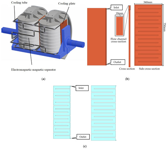
Figure 1.
Schematic diagram of the structure: (a) electromagnetic separator; (b) cooling plate; (c) fluid domain.

Table 1.
Main parameters of the electromagnetic separator.
The cooling plate is crucial for the stable operation of the magnetic separator, as it can effectively dissipate the heat generated during operation and protect the equipment from performance degradation due to overheating. As shown in Figure 1, the cooling plates are placed on both sides of the electromagnetic separator. Pipes are arranged outside the cooling plates to supply cooling fluid, and their internal flow channels are S-shaped. This S-shaped flow channel design extends the flow path and residence time of the cooling fluid within the cooling plates, which helps enhance heat dissipation efficiency.
2.2. Establishment of the Fluid–Thermal Coupling Model
The energy and momentum-related equations for the flowing fluid in the cooling plate can be described by the following equations:
where is the velocity vector (in m/s); μ is the dynamic viscosity of the fluid (in kg/(m·s)); ρ is the fluid density (in kg/m3); p is the fluid pressure (in Pa); is the global body force per unit mass (in N/kg); T is the fluid temperature (K); k is the thermal conductivity of the fluid (in W/(m·K)); and φ refers to viscous dissipation.
By means of the Reynolds number (Re), the flow regime of the fluid can be determined:
where u is the fluid velocity (in m/s); v is the kinematic viscosity (in m2/s).
Since the internal channel of the cooling plate is rectangular, the hydraulic diameter is used to represent the characteristic length:
where a is the length of height the rectangle channel (in mm) and b is the length of the width of the rectangle channel (in mm).
The Nusselt number (Nu) is used to evaluate the heat transfer performance of the fluid:
where h denotes the convective heat transfer coefficient.
Forced convective heat transfer in turbulent pipe flow is commonly described by the Dittus–Boelter equation:
For the purpose of quantitatively analyzing the characteristics of turbulent forced convection heat transfer on the surface of the heat sink plate (i.e., how the heat transfer capacity between the fluid and the plate is affected by the flow regime and fluid properties), the classical turbulent forced convection heat transfer criterion correlation (Dittus–Boelter formula) is introduced:
where Pr refers to the Prandtl number; tw and tf represent the avoidance temperature and fluid temperature, respectively (in °C); since the coolant is heated in the paper, n0 is 0.4.
Due to the viscosity of the fluid, along-the-path resistance is formed within the fluid and between the fluid and the wall surface. To overcome this resistance, along-the-path loss occurs. The along-the-path pressure drop is commonly expressed by the Darcy–Weisbach equation:
where λ is the frictional resistance coefficient; L is the pipe length (in m), and g is the gravitational acceleration (in m/s2).
2.3. Model Assumptions and Setting of Boundary Conditions
To ensure solution accuracy and eliminate the impact of grid precision on the calculation results, the model is meshed using hexahedral grids, with the minimum orthogonality quality guaranteed to exceed 0.2; the mesh diagram is presented in Figure 2. Additionally, a grid independence analysis of the model is conducted. As illustrated in Figure 3, by comparing temperature variations under different grid quantities, it is observed that when the number of grids is less than 4 million, the calculation results exhibit significant sensitivity to the grid quantity. When the grid count reaches 4,863,581, further increases in grid quantity exert minimal influence on the results, and the grid tends to converge. Therefore, during meshing, the grid quantity is ensured to be no less than 5 million to maintain solution accuracy.
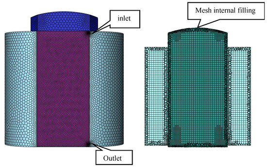
Figure 2.
Mesh diagram of the model.
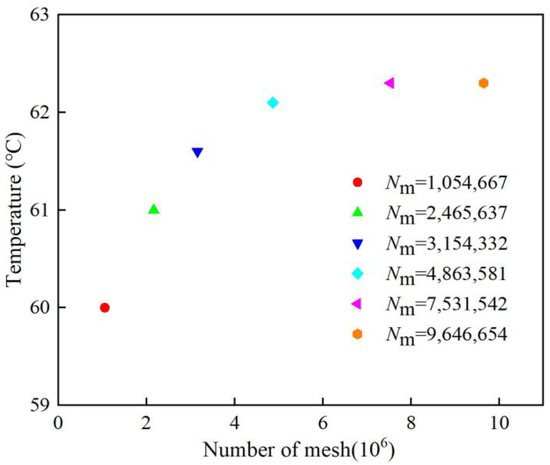
Figure 3.
Grid convergence analysis.
To improve the solution efficiency, the following assumptions are made for the model:
- Each part of the windings generates heat uniformly, and other heat sources are ignored;
- Fluid motion is complex with a large Reynolds number, so the k-Omega turbulence model is used to calculate the flow field of the motor;
- The fluid is incompressible;
- To ensure the accuracy of the solution, polyhedral meshes are set, with their orthogonality quality guaranteed to be above 0.2; the mesh meshing diagram is shown in Figure 3.
- Boundary conditions are set for the model as follows:
- The ambient temperature is set to 25 °C, and all surfaces in contact with air are configured for convective heat transfer;
- The coolant temperature is 25 °C; the specific physical parameters of the coolant and other main materials are shown in Table 2.
Table 2. Main material thermophysical parameters.
- The fluid inlet is set as a velocity inlet; the fluid outlet is set as a pressure outlet.
3. CFD-Based Research on Heat Transfer of Heat Sink
In the practical operation of electromagnetic separators, heat generation is inevitable. Such a heat-induced resistance increase in coils deteriorates the separator’s performance, significantly compromising its stable operation and operational efficiency. Within the thermal management system of electromagnetic separators, the cooling plate serves as the core heat-dissipating component, whose structural parameters play a critical role in determining heat dissipation efficiency, energy consumption levels, and manufacturing costs. To develop a cooling plate design that balances high performance and cost-effectiveness, it is essential to explore how its structural parameters influence cooling performance.
3.1. The Influence of the Number of Water Channels on the Heat Transfer of the Cooling Plate
Coil temperature control is critical for electromagnetic separators. As the core heat-dissipating component, the rationality of the structural design of the cooling plate directly determines its heat dissipation performance. Increasing the number of water channels (n) of the S-shaped channel is an effective way to enhance heat transfer; meanwhile, factors such as flow resistance, manufacturing cost, and reliability are comprehensively considered to determine the optimal value of n. Schematic diagrams of cooling plates with different numbers of channel water channels are shown in Figure 4.
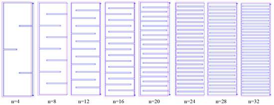
Figure 4.
Cooling plate structures under different numbers of water channels.
The relationship between the pressure drop between the inlet and outlet of the cooling plate and the pump power is as follows:
where Wpump is the pump power, uin is the inlet flow velocity; ΔP is the pressure drop between the inlet and outlet.
By establishing models with different numbers of water channels and performing CFD finite element calculations, the contour plots of the fluid field and temperature field of the cooling plate under different n are obtained, as shown in Figure 5.
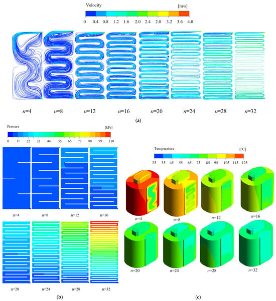
Figure 5.
Comparison of the distribution of the indicators of the magnetic separator and its cooling system with different number of passes: (a) flow velocity distribution of the cooling plate; (b) pressure distribution inside the cooling plate; (c) temperature distribution of the magnetic separator and the cooling plate.
As observed in Figure 5, in terms of the fluid field, when n is small, flow dead zones emerge at the fluid inlet. This is because when coolant enters the wider cooling plate channels from narrower pipes, its velocity drops sharply, causing boundary layer separation and forming dead zones. Under these conditions, the cooling plate exhibits weak heat dissipation capacity, the magnetic separator coils run at higher temperatures, and the internal pressure of the plate is low. As n increases, the cross-sectional area of the cooling plate channels decreases, which in turn reduces the size of the dead zones. Simultaneously, the coolant flow velocity in the plate gradually increases, enhancing the cooling plate’s heat dissipation performance and lowering the coil temperature accordingly. However, this also causes a rise in the pressure drop within the cooling plate.
To further investigate the influence of the number of water channels of the S-shaped cooling plate on its heat dissipation performance, Figure 6 presents the curves of average flow velocity, Nu, maximum coil temperature, and pressure drop obtained from numerical simulations. From Figure 6a and as can be seen from Figure 5, when n increases, the cross-sectional area of the water channels inside the cooling plate decrease. Since the inlet velocity and flow rate are both fixed, according to the continuity equation of fluid, the average flow velocity inside the cooling plate will increase. This improves the heat exchange efficiency and reduces the temperature of the cooling plate. However, due to the bending of the flow channels, both the local resistance and frictional resistance along the path increase, leading to a significant rise in the pressure drop. This requires a pump with higher power to drive the fluid, resulting in an increase in energy consumption cost.
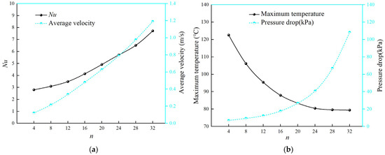
Figure 6.
Changes in performance indicators of the cooling plate with variations in channel turns: (a) Nu and average flow velocity; (b) maximum coil temperature and pressure drop.
From the temperature curve in Figure 6b, the maximum coil temperature decreases gradually as the number of water channels increases. It reaches 120.31 °C at the number (n) of 4 and drops to 69.83 °C at the number (n) of 32. This indicates that increasing the number of channels effectively reduces the coil temperature. Also, the rate of temperature decrease slows down when n exceeds 20.
As shown in the pressure drop curve in Figure 6b, the pressure drop ΔP increases in a quadratic-function relationship with n, causing a drastic rise in pump power. Notably, the growth gradient of the pressure drop spikes when n exceeds 20. Therefore, by comprehensively balancing the heat dissipation capability and economic efficiency of the cooling plate, the optimal number of water channels is determined as n of 20.
The average interpolation method is used for regression fitting of the finite element calculation results in Figure 6, and a system of equations for each parameter with the number of water channels as the variable is given, as shown in Equation (11). This precise system of functional equations provides an engineering reference basis for the calculation of fluid parameters in the water channel structure of the cooling plate. In order to ensure the correctness of the fit, the fitting function will be selected in such a way that the value of R2 is greater than 0.98, the R2 value of the fitted curve is shown in Table 3.
where n denotes the number of water channels, Nu(n) is the fitting function of the Nusselt number with respect to the independent variable n; vavg(n) is the fitting function of the average flow velocity with respect to the independent variable n; Tmax(n) is the fitting function of the maximum temperature with respect to the independent variable n (in °C); and ΔP(n) is the fitting function of the pressure drop with respect to the independent variable n (in kPa).
Table 3.
R2 values for each curve fit of parameter n.
3.2. The Influence of the Channel Cross-Section Area on the Heat Transfer of the Cooling Plate
In the study of cooling plates for electromagnetic separators, the cross-section area of the flow channel has a significant impact on their performance. The cross-sectional area of the flow channel inside the cooling plate is equal to a multiplied by b, as shown in Figure 7. With the width b of the rectangular channel kept constant, the width of the long side a of the rectangular channel is adjusted. Changing the hydraulic diameter Dh alters the height a and cross-sectional area of the channel, which affects the heat dissipation capability of the cooling plate. To investigate the fluid flow characteristics inside the cooling plate under different lengths a, finite element method is used to perform fluid–solid coupling calculations on the electromagnetic separator model, as shown in Figure 8.
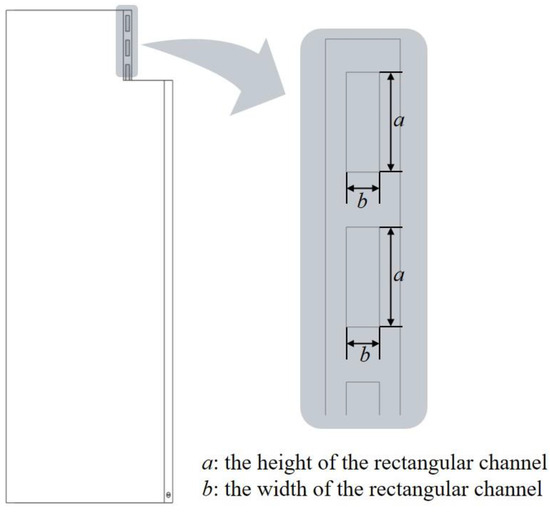
Figure 7.
Flow channel cross-sectional view.
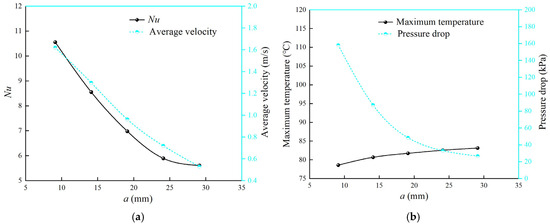
Figure 8.
Changes in cooling plate performance under different height a: (a) Nu and average flow velocity; (b) maximum magnetic separator temperature and pressure drop between cooling plate inlets and outlets.
The parameter curves characterizing the variation in height a of the cooling channel are presented in Figure 8. As a increases (and, consequently, so does hydraulic diameter Dh), Nu, average fluid velocity, and pressure drop decrease gradually, while the maximum coil temperature of the magnetic separator increases progressively. This is because, for a steady flow of incompressible fluids, flow velocity is inversely proportional to the channel’s cross-sectional area. Increasing the long side a increases the channel’s cross-sectional area, thereby reducing fluid velocity. Since flow velocity correlates positively with the heat transfer coefficient, the Nusselt number decreases, in turn causing the maximum temperature of the magnetic separator to rise. According to the Darcy–Weisbach equation, a pressure drop is positively correlated with flow velocity, resulting in a corresponding decrease in the pressure drop.
From the temperature curve in Figure 8b, it can be seen that as a increases, the maximum temperature of the coil gradually rises. When a is 9 mm, the maximum temperature of the coil is 78.6 °C; after that, the temperature continues to increase, and when a reaches 24 mm, the maximum temperature rises to 83.16 °C. When a exceeds 20 mm, the temperature rise becomes relatively slow.
As shown in the pressure drop curve in Figure 8b, as a increases, the pressure drop decreases sharply. When a is 9 mm, the pressure drop at the coolant inlet inside the cooling plate is as high as 158.23 kPa; when a is 29 mm, the pressure drop decreases to 26.78 kPa. The pressure drop decreases drastically at the beginning, but when a reaches 24 mm, the rate of decrease becomes slow.
The foregoing analysis for the electromagnetic separator indicates that reducing the height a of the cross area can enhance Nu and average fluid velocity, improve the heat transfer performance of the cooling plate, and lower the maximum operating temperature of the magnetic separator. However, it causes a sharp increase in the inlet–outlet pressure drop, resulting in a significant rise in pump power consumption, thereby compromising economic efficiency. The maximum temperature of the electromagnetic magnetic separator and the cooling liquid inlet–outlet pressure drop are selected as the evaluation guarantee, and the intersection of the temperature and pressure drop curves is selected as the preferred point. At this point, the height a is determined to be 24 mm, with a corresponding hydraulic diameter Dh of 12 mm.
Fitting is performed on the curves in Figure 8, and a system of equations for each parameter with the cross-sectional height a as the variable is derived as shown in Equation (12). These precise functional equations provide an engineering reference for calculating the fluid parameters of the cooling plate structure. In order to ensure the correctness of the fit, the fitting function will be selected in such a way that the value of R2 is greater than 0.98. The R2 value of the fitted curve is shown in Table 4.
where a is the height of the rectangular channel (in mm); Nu(a) is the fitting function of the Nusselt number with respect to the independent variable a; vavg(a) is the fitting function of the average flow velocity with respect to the independent variable a; Tmax(a) is the fitting function of the maximum temperature with respect to the independent variable a (in °C); and ΔP(a) is the fitting function of the pressure drop with respect to the independent variable a (in kPa).
Table 4.
R2 values for each curve fit of parameter a.
4. Optimization Strategy of the Cooling Plate
4.1. An Innovative Semicircular Groove Structure
Heat transfer enhancement structures are used to improve flow mixing, thereby promoting heat transfer enhancement in microchannels with small hydraulic diameters under laminar flow. For cooling plates with smooth wall surfaces, heat dissipation is relatively unidimensional, mainly relying on heat conduction through the velocity gradient of the main flow. After introducing expansive grooves on the inner wall surfaces of the cooling plate, the contact area between the coolant and the cooling plate increases; on the other hand, the addition of expansive grooves disrupts the boundary layer to enhance turbulence, and roughness peaks induce vortices, thus strengthening convective heat transfer.
In this study, a type of semicircular groove is introduced inside the cooling plate to improve flow performance and enhance the heat transfer capability of the structure, as illustrated in Figure 9. The groove radius r is adopted as the control variable for groove size, and the groove spacing l is used to characterize the number of grooves. For a given length, the number of grooves increases as the groove spacing decreases. This work investigates the influence of multi-parameter variations in the grooves on the cooling plate performance.
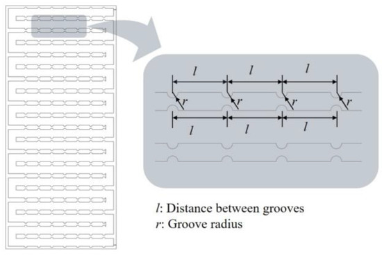
Figure 9.
Schematic diagram of the semicircular groove structure.
4.2. Optimization Strategy Based on RSM and Genetic Algorithm
Based on the previous analysis, where the number of water channels of the water channel in the S-type cooling plate is determined as 20 and the hydraulic diameter as 12 mm, periodic semicircular grooves are introduced into the S-type cooling plate to alter its heat transfer capacity. To investigate the influence of the same periodic grooves on the cooling plate, with the groove radius adopted as the variable parameter characterizing groove size, a functional model describing the impact of groove parameters on heat dissipation performance is established using RSM, while also exploring the effects of different grooving patterns on the cooling plate’s performance.
To achieve optimal heat dissipation performance and economy, the genetic algorithm is employed to optimize the optimal structural parameters of the grooves based on the functional model established by response surface methodology, ultimately completing the optimized design of the cooling plate for the electromagnetic separator.
To effectively ensure higher precision and enhance the accuracy of optimization objectives, a second-order function is employed to fit the mathematical model of the optimization objectives.
where y represents the system response; β is the regression coefficient; t denotes the number of independent variables; ε stands for the fitting error; and x is the input variable.
To enhance the operational stability of the electromagnetic separator and reduce its temperature, this paper takes reducing the maximum temperature of the electromagnetic separator and improving the cooling efficiency as optimization objectives.
Defining the optimization range can reduce experiment time and improve experimental efficiency, and selecting an appropriate groove opening radius is crucial. The groove radius should not be too small, as an excessively small groove opening will increase the difficulty of the manufacturing process, thereby raising costs. Therefore, the groove radius is chosen to be no less than 1 mm here. Meanwhile, the groove opening should not be too large either, as an excessively large opening will reduce the structural strength of the plate, so the groove radius is limited to within 5 mm. Due to geometric constraints, an excessively large groove opening distance will cause structural conflicts; thus, the opening distance is limited to the range [10,45]. The optimized variables must satisfy the following constraints:
where l denotes the distance between open grooves (in mm), and r denotes the radius of the semicircular groove (in mm).
The CFD finite element method was applied to conduct finite element simulation calculations for two variables: groove opening radius and opening spacing. The fitted curves of the response surfaces and contour plots of the optimization objectives with respect to each factor are shown in Figure 10, and the following conclusions are obtained:
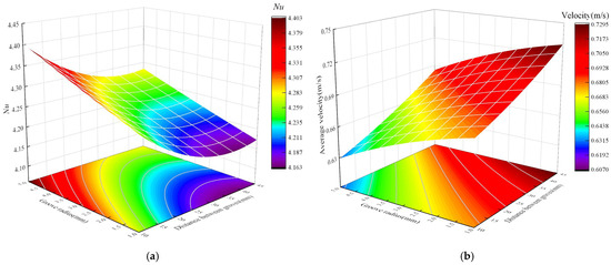
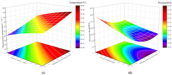
Figure 10.
Response surface modeling for optimization objectives.: (a) Nu of the fluid boundary; (b) average flow rate of the fluid in the cooling plate; (c) high temperatures inside the magnetic separator; (d) pressure drop between cooling plate inlets and outlets.
- An increase in groove radius and a decrease in groove spacing both increase the roughness of the inner wall of the cooling plate, enhance the flow resistance of the fluid, and ultimately reduce the average flow velocity of the coolant in the cooling plate. Nu varies between 4.163 and 4.403, with a small overall trend, ranging from a minimum when l is 45 mm and r is 1 mm to a maximum when l is 10 mm and r is 5 mm;
- An increase in groove radius and a decrease in groove spacing strengthen the turbulence effect, thereby improving the heat transfer capacity of the wall. However, since their impact on flow velocity is negative, under the mutual restriction of these two conditions, Nu shows a trend of first increasing and then decreasing with the increase in groove radius and the decrease in groove spacing. The mean flow velocity varies from 0.607 m/s to 0.7295 m/s, with a minimum when l is taken as 5 mm and r is taken as 1 mm, and a maximum when l is taken as 10 mm and r is taken as 5 mm;
- An increase in groove radius and a decrease in groove spacing can effectively enhance the heat transfer capacity of the cooling plate, and both can reduce the maximum temperature of the magnetic separator. The maximum temperature varies from 67.9 to 67.9, and the overall trend is not significant, with a minimum when l is 45 mm and r is 1 mm, and a maximum when l is 10 mm and r is 5 mm;
- An increase in groove radius and a decrease in groove spacing lead to an increase in pressure drop. This is because an increase in groove radius changes the flow channel shape and roughness, while more dense grooves further increase flow resistance; the increased fluid flow resistance ultimately results in a rise in pressure drop. The pressure drop varies from 4.163 kPa to 33.96 kPa, with the overall trend being small, taking a minimum when l is taken as 5 mm and r is taken as 1 mm and a maximum when l is taken as 10 mm and r is taken as 5 mm.
The mathematical models of the relationships between each response and each factor fitted from Figure 10 lay a foundation for multi-objective optimization. The fitted regression equations for the maximum temperature, pressure drop, and flow velocity of the electromagnetic separator, and Nu are as follows:
where Nu(r,l) is the fitting function of the Nusselt number with respect to the independent variables r and l; vavg(r,l) is the fitting function of the average flow velocity with respect to the independent variables r and l; Tmax(r,l) is the fitting function of the maximum temperature with respect to the independent variables r and l (in °C); and ΔP(r,l) is the fitting function of the pressure drop with respect to the independent variables r and l (in kPa).
The optimization objective is to minimize the maximum temperature of the coil and the pressure drop of the cooling plate. To ensure that the electromagnetic separator coil maintains a relatively low temperature while the cooling system still provides high cooling efficiency, the primary goal of the optimization calculation in the multi-objective optimization process is to reduce the maximum temperature of the coil. During the optimization process, the weighting assigned to the set maximum temperature of the coil is slightly higher than that of the coolant pressure drop; therefore, the weighting coefficients for the maximum temperature of the coil and the pressure drop are set to 0.6 and 0.4, respectively. The genetic algorithm is used to optimize the objective function, with the initial conditions of the genetic algorithm set as follows: a population size of 200, a maximum of 150 generations, an elite count of 5, and a crossover rate of 0.70. The setting conditions and results of the genetic algorithm are shown in Figure 11. Through optimization using the genetic algorithm, the optimal solution is obtained, and the predicted values of the maximum coil temperature and pressure drop are 68.74 °C and 33.16 kPa, respectively. Corresponding to this optimal solution, the radius of the open groove on the water channel baffle is 4.5 mm and the spacing of the open grooves is 10 mm, which corresponds to the region with relatively lower temperature and relatively higher pressure drop on the response surface in Figure 10.
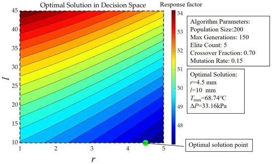
Figure 11.
Genetic algorithm optimization condition setting and results.
4.3. Finite Element Analysis of Optimization Results
Due to the simplifying assumptions of the theoretical model, uncertainties in experimental measurements, and deviations of the actual behavior of the fluid from the ideal situation, it is inevitable that there will be a certain discrepancy between the calculated values and the predicted values. In order to accurately and quantitatively measure this discrepancy, so as to more accurately assess the reliability of the model, optimize the design of the heat sink structure, and improve the understanding of the fluid performance, we introduce the following error analysis formula.
where PRE is the relative error, yc is the simulation calculated value and yp is the predicted value.
A finite element model was established based on the parameters obtained from the final optimization, and the cooling plate was fabricated using the optimized cooling plate parameters mentioned above. Through CFD finite element simulation, a comparative simulation analysis was conducted for the cases before and after grooving. From the finite element simulation results of the optimized model with grooves on the fluid wall, the flow velocity, pressure, and temperature distributions as shown in Figure 12 were obtained, and the results before and after optimization are presented in Table 5.
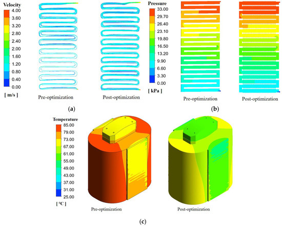
Figure 12.
Comparison of individual results of CFD finite element cloud maps of results before and after optimization: (a) flow rate distribution of fluids within the cooling; (b) pressure distribution on the inner wall surface of the cooling plate; (c) temperature distribution of electromagnetic magnetic separator.
Table 5.
Comparison of indicators for optimized sequential cooling plates.
By comparing the results before and after optimization, the following conclusions are drawn:
- Through a comparative analysis of the predicted values and finite element calculation results, the findings show that the error rates of all key indicators (e.g., flow velocity, pressure drop, temperature) are controlled within 2%. These errors arise from the interaction of the algorithm’s inherent approximation, computing resource limitations, and model errors; however, the error magnitudes are relatively small and acceptable in engineering practice. These data fully demonstrate that the mathematical model, boundary condition settings, and algorithm employed in the structural parameter optimization of the cooling plate exhibit high accuracy and reliability.
- Compared with the cooling plate with smooth walls, the introduction of the groove structure significantly changes the geometric shape of the flow channel. This causes a significant increase in internal pressure when the fluid flows through the groove area due to increased local resistance (such as eddy current loss and boundary layer separation). Additionally, the protrusions or depressions of the grooves have a retarding effect on fluid flow. Although the local flow velocity in narrow or deep grooves may increase, the overall average flow velocity is lower than that of the smooth-walled cooling plate.
- By comparing the experimental data, it can be seen that after introducing the groove structure, the thermal management performance of the electromagnetic coil is significantly optimized. The maximum temperature of the coil decreases from 82.45 °C (with smooth walls) to 69.82 °C, a reduction of 12.63 °C, with a decrease rate as high as 15.31%. This indicates that the groove structure effectively enhances the convective heat transfer process by increasing wall roughness and promoting fluid disturbance (such as increased turbulence intensity or generation of secondary flow), thereby accelerating the heat transfer from the coil to the cooling medium.
5. Experiment Validation
This test platform as Fig.13 is mainly composed of four parts: the prototype system, power supply unit, temperature monitoring equipment, and cooling water supply system, with specific specifications listed in Table 6. During the experiment, four cooling plates were arranged on both sides of the two coils, and coolant was continuously supplied by a water chiller. Both the excitation coils and cooling plates were hermetically installed inside the drum, shown as Figure 13; due to the sealed structure, direct measurement using PT100 temperature sensors was not feasible. Therefore, preliminary temperature measurement of the cooling plates was conducted using Thermax temperature indicator strips in this study. Given the limited accuracy of Thermax temperature indicator strips, the drum shell was immediately disassembled after 5 h operation, and a Fluke infrared thermometer was used to quickly measure the maximal temperature of the coil. Since the coils are completely sealed inside the drum, their heat dissipation is mainly achieved through the cooling plates, and the external environment has little impact on the heat dissipation results. To ensure the experimental results would be as accurate as possible, the environmental conditions were controlled during the experiment to be windless with an ambient temperature of 25 °C, and a 5 h continuous rated operation test was conducted on the electromagnetic separator.
Table 6.
The main equipment and parameters of the experiment.
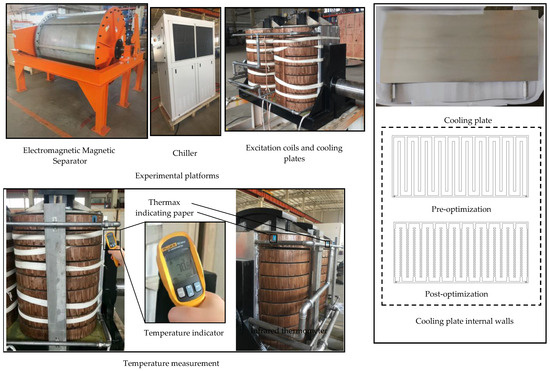
Figure 13.
Experimental platforms.
Based on the experimental results, temperature data of the optimized electromagnetic separator coils and the temperature rise simulation curves before and after optimization were obtained, as shown in Figure 14. When the temperature reaches a stable state, the simulation results show that the coil temperatures before and after optimization are 82.45 °C and 69.82 °C, respectively. The stable temperatures of the two test points on the optimized coil measured in the experiment are 70 °C and 70.5 °C, respectively, with errors of 0.26% and 0.96% compared with the simulation values. All measured temperatures are far below the 120 °C limit allowed for coil insulation, which indicates that the system has a sufficient safety margin. The error between the experimental and simulation results is small and can be neglected in engineering applications, which further verifies the accuracy of the simulation model and the feasibility of the optimization scheme.
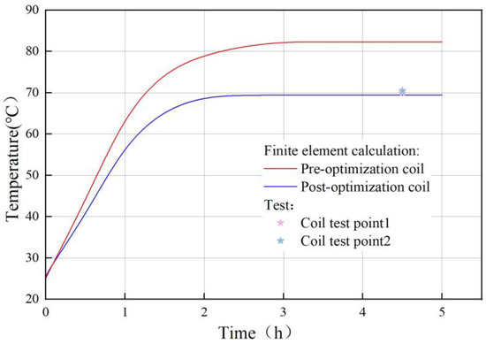
Figure 14.
Finite element temperature rise curves versus experimental temperatures.
6. Conclusions
In this study, the structural optimization design of the S-type cooling plate for the electromagnetic separator was carried out. The heat dissipation performance of the cooling plate under different structural configurations was analyzed using the CFD finite element method, and a multi-parameter and multi-objective algorithm was applied for the structural optimization design of the cooling plate. The following conclusions are drawn:
- The increase in the number of cooling channels significantly improves the coolant flow rate and Nu of the cooling plate, thereby enhancing its heat dissipation capability and reducing the coil temperature of the electromagnetic separator. However, it also leads to an increase in pressure drop, which raises the required pump power for the cooling plate. Therefore, when determining the number of water channels for the S-shaped water channel, it is necessary to balance economic efficiency.
- With the number of channels fixed, reducing the height dimension can increase the coolant flow velocity and Nu, further enhancing the heat transfer capacity of the cooling plate. Nevertheless, a decrease in hydraulic diameter causes a sharp increase in flow channel resistance, resulting in multiple increases in the inlet–outlet pressure drop.
- This paper proposed a semi-circular groove structure, and the structural parameters of the grooves were optimized based on RSM and the genetic algorithm. The results show that the introduction of grooves enhances the turbulence effect, further improving the heat transfer capacity of the cooling plate. After optimization, the maximum temperature decreased by 12.63 °C with a reduction rate of 15.31%, and the error between the predicted values and finite element simulation results was less than 2%, verifying the accuracy of the optimization method. Despite the presence of a small boost in pressure drop, a smaller mention is acceptable.
- A cooling plate was fabricated with optimized parameters, and an experimental platform for the electromagnetic separator and its cooling system was built. The experimental results are consistent with the simulation results, indicating that optimization can effectively enhance the heat dissipation capacity of the cooling plate, verify the accuracy and feasibility of the simulation, and provide a reference for subsequent structural design of cooling plates.
Author Contributions
Conceptualization, J.D., K.L. and H.R.; Methodology, X.W., H.R., H.L. and K.L.; Software, J.D., H.R., H.L. and K.L.; Formal analysis X.W. and H.L.; Investigation, X.W. and J.D.; Writing—original draft, J.D., H.L. and K.L.; Writing—review and editing, J.D., K.L. and X.W.; Supervision, X.W. and J.D. All authors have read and agreed to the published version of the manuscript.
Funding
This research was funded by Science and Technology Project of Tianjin, grant number 23YDTPJC00710.
Data Availability Statement
The original contributions presented in this study are included in the article. Further inquiries can be directed to the corresponding author.
Conflicts of Interest
The authors declare no conflicts of interest.
Abbreviations
The following abbreviations are used in this manuscript:
| PMCP | Parallel microchannel cooling plates. |
| DSC-CP | A double serpentine channel cooling plate. |
| TMS | Thermal management systems. |
| GV-CNF | Gradually varied circular notched fins. |
| RSM | Response Surface Methodology. |
| CFD | Computational Fluid Dynamics. |
| Re | Reynolds number. |
| Nu | Nusselt number. |
| Pr | Prandtl number. |
References
- Ma, N.; Houser, J.B. Recycling of steelmaking slag fines by weak magnetic separation coupled with selective particle size screening. J. Clean. Prod. 2014, 82, 221–231. [Google Scholar] [CrossRef]
- Cao, Q.; Han, X.; Lai, Z.; Xiong, Q.; Zhang, X.; Chen, Q.; Xiao, H.; Li, L. Analysis and reduction of coil temperature rise in electromagnetic forming. J. Mater. Process. Technol. 2015, 225, 185–194. [Google Scholar] [CrossRef]
- Wang, Q.; Dai, Y.; Huang, H.; Song, S.; Zhang, B.; Kim, K.; Oh, S. Development of conduction-cooled high temperature superconducting magnet. IEEE Trans. Appl. Supercond. 2005, 15, 2332–2335. [Google Scholar] [CrossRef]
- Rey, C.; Hoffman, W.; Cantrell, K.; Eyssa, Y.; VanSciver, S.; Richards, D.; Boehm, J. Design and fabrication of an HTS reciprocating magnetic separator. IEEE Trans. Appl. Supercond. 2002, 12, 971–974. [Google Scholar] [CrossRef]
- Chen, K.; Chen, Y.; Song, M.; Wang, S. Multi-parameter structure design of parallel mini-channel cold plate for battery thermal management. Int. J. Energy Res. 2020, 44, 4321–4334. [Google Scholar] [CrossRef]
- Hamrang, A.; Abdollahzadeh, M.; Kermani, M.; Rahgoshay, S. Numerical simulation of the PEM fuel cell performance enhancement by various blockage arrangement of the cathode serpentine gas flow channel outlets/inlets. Int. J. Heat Mass Transf. 2022, 186, 122475. [Google Scholar] [CrossRef]
- Raza, W.; Islam, N.; Samad, A. Design and analysis of a novel Bi-layer curved serpentine chaotic micromixer for efficient mixing. Chem. Eng. Process.-Process Intensif. 2023, 183, 109246. [Google Scholar] [CrossRef]
- Masaeli, N.; Afshari, E.; Baniasadi, E.; Baharlou-Houreh, N. Performance studies of a membrane-based water and heat exchanger using serpentine flow channels for polymer electrolyte membrane fuel cell application. Appl. Therm. Eng. 2023, 222, 119950. [Google Scholar] [CrossRef]
- Siddiqui, M.; Shahab, M.; Siddiqui, O.; Ali, H.; Zubair, S.M. A comprehensive multi-physics model of photovoltaic modules with non-uniform solar concentration and serpentine cooling. Energy Convers. Manag. 2022, 271, 116266. [Google Scholar] [CrossRef]
- Imran, A.A.; Mahmoud, N.S.; Jaffal, H.M. Analysis of channel configuration effects on heat transfer enhancement in streamline-shaped cold plates used in battery cooling system: A comparative study. Int. Commun. Heat Mass Transf. 2024, 155, 107570. [Google Scholar] [CrossRef]
- Yogeshwar, D.; Repaka, R.; Marath, N.K. A double serpentine channel liquid cooling plate for hotspot targeted cooling of lithium-ion batteries in a battery module. Int. J. Therm. Sci. 2025, 209, 109521. [Google Scholar] [CrossRef]
- Zhang, H.; Liu, Y.; Guo, J. A Study on the Heat Dissipation Effects During the Meshing Process of Involute Gears with Variable Tooth Thickness. Machines 2025, 13, 686. [Google Scholar] [CrossRef]
- Mubashir, M.; Xu, J.; Guo, Z.; Wang, X.; Wang, H.; Qiao, F.; Li, E.; Mei, X. Numerical investigation of a novel cold plate design with uniform circular hollow fins for battery thermal management systems. Appl. Therm. Eng. 2024, 237, 121791. [Google Scholar] [CrossRef]
- Zhang, L.; Ma, Y.; Lv, M.; Wang, X.; Shi, X. Performance-Enhanced Double Serpentine Minichannel Heat Sink for Phased-Array Radar High-Heat-Flux Chip Cooling. Electronics 2025, 14, 2246. [Google Scholar] [CrossRef]
- Gao, H.; Hou, X.; Ma, W.; Ma, Y. Design and Thermal Performance Analysis of a Liquid Cooling Plate Based on Gradually Varied Circular Notched Fins for Lithium-Ion Batteries. Processes 2025, 13, 924. [Google Scholar] [CrossRef]
- Li, Q.-X.; Pan, M.; Dong, Y.-H. Turbulence modulation and heat transfer enhancement in channels roughened by cube-covered surface. Comput. Fluids 2018, 165, 33–42. [Google Scholar] [CrossRef]
- Liu, H.; Gao, X.; Zhao, J.; Yu, M.; Niu, D.; Ji, Y. Liquid-based battery thermal management system performance improvement with intersected serpentine channels. Renew. Energy 2022, 199, 640–652. [Google Scholar] [CrossRef]
- Fan, L.; Li, J.; Chen, Y.; Zhou, D.; Jiang, Z.; Sun, J. Study on the cooling performance of a new secondary flow serpentine liquid cooling plate used for lithium battery thermal management. Int. J. Heat Mass Transf. 2024, 218, 124711. [Google Scholar] [CrossRef]
- Ansari, M.Q.; Zhou, G. Flow and heat transfer analysis of microchannels structured with rectangular surface roughness. Chem. Eng. Process.-Process Intensif. 2020, 156, 108066. [Google Scholar] [CrossRef]
- Gorzin, M.; Ranjbar, A.A.; Hosseini, M.J. Experimental study on serpentine minichannel heat sink: Effect of rib existence and distance. Int. J. Therm. Sci. 2022, 173, 107397. [Google Scholar] [CrossRef]
- Yang, M.; Zhang, S.; Tian, H.; Lv, L.; Han, J. Research on Thermal Characteristics and Algorithm Prediction Analysis of Liquid Cooling System for Leaf Vein Structure Power Battery. Batteries 2025, 11, 326. [Google Scholar] [CrossRef]
- Guo, Z.; Rao, Y.; Li, Y.; Wang, W. Experimental and numerical investigation of turbulent flow heat transfer in a serpentine channel with multiple short ribbed passes and turning vanes. Int. J. Therm. Sci. 2021, 165, 106931. [Google Scholar] [CrossRef]
- Yu, C.; Li, H.; Chen, J.; Qiu, S.; Yao, F.; Liu, X. Investigation of the thermal performance enhancement of a photovoltaic thermal (PV/T) collector with periodically grooved channels. J. Energy Storage 2021, 40, 102792. [Google Scholar] [CrossRef]
- Kani, T.G.; Ghahremani, A. Optimal design of heat pipes for city gate station heaters by applying genetic and Bayesian optimization algorithms to an artificial neural network model. Case Stud. Therm. Eng. 2024, 55, 104203. [Google Scholar] [CrossRef]
- Li, Z.; Zhu, W.; Wang, B.; Wang, Q.; Du, J.; Sun, B. Optimization of cooling water jacket structure of high-speed electric spindle based on response surface method. Case Stud. Therm. Eng. 2023, 48, 103158. [Google Scholar] [CrossRef]
- Gao, G.; Xu, F.; Xu, J. Parametric optimization of FDM process for improving mechanical strengths using Taguchi method and response surface method: A comparative investigation. Machines 2022, 10, 750. [Google Scholar] [CrossRef]
- Guo, R.; Li, L. Heat dissipation analysis and optimization of lithium-ion batteries with a novel parallel-spiral serpentine channel liquid cooling plate. Int. J. Heat Mass Transf. 2022, 189, 122706. [Google Scholar] [CrossRef]
- Xu, X.; Tong, G.; Li, R. Numerical study and optimizing on cold plate splitter for lithium battery thermal management system. Appl. Therm. Eng. 2020, 167, 114787. [Google Scholar] [CrossRef]
- Liu, J.; Ai, M. Structural optimization design and heat transfer characteristics of air-to-air cooled high voltage motor heat exchanger. Case Stud. Therm. Eng. 2022, 40, 102532. [Google Scholar] [CrossRef]


Disclaimer/Publisher’s Note: The statements, opinions and data contained in all publications are solely those of the individual author(s) and contributor(s) and not of MDPI and/or the editor(s). MDPI and/or the editor(s) disclaim responsibility for any injury to people or property resulting from any ideas, methods, instructions or products referred to in the content. |
© 2025 by the authors. Licensee MDPI, Basel, Switzerland. This article is an open access article distributed under the terms and conditions of the Creative Commons Attribution (CC BY) license (https://creativecommons.org/licenses/by/4.0/).