Abstract
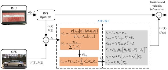
The key technologies for advanced autonomous vehicles include those relating to perception, decision making, and execution. Path-tracking control in autonomous vehicles is heavily dependent on their positioning system. Therefore, the development of low-cost and reliable positioning systems is crucial to improving perception and decision-making technologies for autonomous vehicles. Although the accuracy of the global positioning system (GPS) is extremely high, it is vulnerable to interference. Further, despite the low positioning accuracy of inertial navigation systems (INSs), their robustness is notably high. Therefore, an integrated navigation information method based on the Adaptive Particle Filter and the Iterative Kalman Filter (APF-IKF) was developed in this study. Firstly, an integrated navigation system model was established. Then, the IKF was adopted to estimate the speed, latitude and longitude errors of the INS. Thirdly, the newest estimated error results were introduced into the APF to optimize the distribution function, and the particle quality was improved. In this process, the APF can filter non-Gaussian noise, preliminarily estimate the error, optimize the result with the IKF and correct the output information of the INS with the final estimated error. Finally, by using differential GPS positioning as the benchmark, we built a real-vehicle test platform with a low-cost and low-precision GPS and inertial units and carried out a series of real-vehicle tests. The experimental results show that compared with the traditional KF method, APF-IKF can significantly improve the positioning accuracy and robustness of the system.
1. Introduction
Intelligent driving technology has emerged against the backdrop of a new wave of technological revolutions. It integrates modern sensor technology, information and communication technology, automatic control technology and more [1,2,3,4,5,6]. With the critical need for highly reliable and precise positioning and attitude information, navigation systems are increasingly playing a more significant role in intelligent driving systems, which makes them a hotbed of research and development [7,8,9,10].
With the advantages of high positioning accuracy, the GPS is widely used in the fields of aerospace and vehicles [11,12,13,14,15]. However, with weak anti-interference ability, strict requirements on the environment for vehicles and high susceptibility to electromagnetic waves or surrounding buildings, the GPS is not suitable for application in intelligent vehicles on its own. As INSs have a strong anti-interference ability and can independently obtain continuous three-dimensional space location and orientation data under any weather conditions, and in medium environments, they can measure the complete information of the motion state of a mass body with steady output. Therefore, INSs are increasingly applied in vehicles [16,17,18,19,20,21,22,23].
In practical applications, the price of high-precision inertial navigation systems is high. Meanwhile, although the widely used micro-electromechanical systems have a low cost, they have null drift and noise, meaning slow error accumulation occurs over time when they are used alone [24]. In order to make up for the deficiencies of INSs and the GPS, integrated navigation technologies have been widely developed. Alireza Shaghaghian proposed a GPS/INS fusion method based on the improved Kalman filter, which improves the estimation of position and velocity in navigation problems by integrating classic and modern control techniques [25]. Chen Zhimin and Yuan Xinqu researched the GPS/INS loose/tight coupling algorithm based on the EKF and achieved good positioning results [26]. Rongjian Wang proposed a multi-model filtering method for tracking different motion models and filtering to improve fusion positioning accuracy and robustness, enabling high-precision, high-availability positioning in complex environments [27]. To solve the problem of EKF performance degradation when system nonlinearity increases or measurement covariance is inaccurate, Jiang Haitao proposed an extended state observer (ESO) to improve the performance of loosely coupled GPS/INS integrated navigation with accurate measurement modeling [28]. Kyunghyun Ryu compared the effects of the navigation fusion method based on the EKF and UKF. Through the comparison of aircraft attitude estimation effects under a fixed trajectory and variable trajectory, it was verified that the UKF could estimate position and attitude more accurately in nonlinear regions [29].
To reduce the multi-path effect of GNSS in large cities, Guohao Zhang et al. proposed an integrated navigation positioning algorithm based on the adaptive Kalman filter. The positioning accuracy was improved on the basis of the traditional Kalman filter by adjusting the measurement noise covariance at different positioning accuracy values [30]. Yahui Liu proposed an integrated navigation method of the adaptive Kalman filter based on attenuation factors; this algorithm continuously updates the covariance of process and measurement noise and effectively suppresses white Gaussian noise by collecting the estimated and observed values in order to achieve the expected aim [31]. Chuang Zhang et al. studied the GPS/IMU/LOG integrated navigation system based on the AFPF, addressed sample depletion, improved the particle quality and verified the algorithm’s effectiveness with experiments [32]. The above research methods satisfactorily deal with Gaussian noise.
Although existing research methods such as improved Kalman filters, loose/tight coupling algorithms, multi-model filtering, extended state observers and adaptive Kalman filters have made significant achievements in enhancing the performance of INS/GPS integrated navigation systems, they still possess certain limitations. They are often sensitive to model linearization and Gaussian noise assumptions, which may render them ineffective in dealing with nonlinearities and non-Gaussian noise. Moreover, they might require intricate tuning and are quite susceptible to variations in sensor quality and environmental conditions, with high computational demands that complicate the management of multiple models simultaneously. Furthermore, despite the increase in system complexity and cost due to the incorporation of auxiliary sensors, improper fusion process management could introduce new sources of error. Moreover, environmental noise has a non-ignorable effect on GPS/INS integrated navigation, which is influenced not only by Gaussian white noise but also by non-Gaussian noise caused by random environmental noise [33].
In practical industrial applications, the predominant approach employed in a unified navigation system is the Kalman filtering algorithm. The Kalman filtering algorithm is primarily applicable to linear systems and situations involving Gaussian noise. Its performance deteriorates significantly in the case of nonlinear systems. The auxiliary particle filter integrates the concepts of particle filtering and iterative Kalman filtering, enabling it to address nonlinear systems and non-Gaussian noise scenarios. Assisted particle filtering is capable of handling a wide range of complex dynamic systems and measurement models. By sampling from the prior probability density function and iteratively updating and resampling the samples based on the measurement data, assisted particle filtering can effectively approximate the true posterior probability density function, leading to more precise estimation results.
The posterior probability density function of the system may exhibit a multimodal distribution, posing a challenge for the Kalman filtering algorithm. However, the auxiliary particle filter excels in representing the multimodal distribution through its particle set, thereby yielding more precise estimation results. Even if the model exhibits errors or noise in its statistical characteristics that deviate from practical assumptions, the auxiliary particle filter can still yield relatively accurate estimation results. In terms of robustness, the auxiliary particle filter demonstrates resilience to variations in model errors and noise statistical characteristics.
In this study, we thus developed an information fusion method for navigation systems using APF-IKF (Adaptive Particle Filter–Iterated Kalman Filter). We established a combined navigation error model that informed the development of the APF-IKF algorithm. The empirical probability distribution, as well as the system state estimation and variance of the APF, are optimized by incorporating the latest observational data from the IKF. This approach addresses issues such as particle impoverishment and degradation, effectively mitigating the influence of non-Gaussian noise. By integrating the current error value with the estimated and measured values, we can derive an optimal error estimate in real-time, which is then used to refine the INS information, producing the final output. This method effectively counteracts external disturbances in measurement values and model errors, enhancing the precision of the integrated navigation system. To validate the efficacy and superiority of the algorithm presented in this study, we constructed a MATLAB (2017 version)/Simulink error model. A reference trajectory was generated based on real-vehicle testing, utilizing the dual-antenna differential GPS. We then compared the positioning results of a standalone INS, the non-differential GPS and the integrated INS/GPS, analyzing the experimental outcomes.
The main contribution of this study is the proposal of a novel INS/GPS integration method that combines an Adaptive Particle Filter (APF) with the Iterative Kalman Filter (IKF) to achieve more accurate state estimation. Our approach is innovative in the following aspects:
- (1)
- We developed an improved APF algorithm that adjusts the empirical probability distribution of particles by incorporating a combined navigation error model, thereby effectively addressing non-Gaussian noise and particle degradation issues.
- (2)
- By integrating the IKF with an APF, our method provides more precise error estimates and corrections without compromising computational efficiency, which is crucial to improving positioning accuracy in dynamic environments.
- (3)
- We conducted experimental validations that demonstrate the superiority of our method in terms of accuracy and robustness over traditional INS/GPS integration methods, particularly in complex environments.
- (4)
- We also showed how the effectiveness of the proposed method can be further validated with Hardware-In-the-Loop (HIL) simulations and real-vehicle tests, providing a solid foundation for practical applications.
In summary, the results of this research study not only show enhanced precision and reliability of the INS/GPS integrated navigation system but also open up new possibilities for the application of low-cost MEMS sensors in the field of high-precision navigation. These contributions are significant for the development of intelligent driving technology and may promote the widespread use of autonomous vehicles.
This paper is organized as follows: In Section 2, the GPS/INS integrated navigation system model is presented as our proposal for a combined estimation method. In Section 3, the combined APF-IKF and the iteration method are proposed in detail. In Section 4, we present the verification of the proposed method based on experimental vehicle tests. Finally, the conclusion is described in Section 5.
2. Steering and Braking Cooperative Control Model
The development of an integrated INS and GPS navigation model is presented in this section. The directions of east, north and sky were selected as the reference coordinate system. The system state variable X(t) mainly includes the error angle of the platform, speed and position deviations, and the null drift errors of the single gyroscope and accelerometer, which can be expressed as
Above, X(t) is a fifteen-dimensional system state vector, and , and represent platform misalignment angles in the directions of east, north and sky in the navigation coordinate system, respectively. , and represent the speed errors in the directions of east, north and sky in the navigation coordinate system, respectively. , and are the longitude, latitude and elevation deviations in the directions of east, north and sky, respectively. , and are the gyroscopic drift errors. , and are the accelerometer errors. The modeling of the errors of the inertial navigation system is shown as follows.
The errors of the gyroscope mainly include the null drift, high-frequency white noise drift and slow-varying drift of the Markov chain every time the application starts. The reference gyroscope errors can be expressed as
Above, represents the null drift of the gyroscope, represents a first-order Markov process, represents white noise drift and represents x, y and z.
satisfies
After the gyroscope starts each time, the null drift value does not change.
The formula is shown as follows:
The gyroscope produces a slow fluctuation over time based on the drift of a constant value. This fluctuation is not completely random and has a certain correlation with the value of the previous moment. Therefore, the slow drift can be expressed with the first-order Markov process.
Accelerometer errors mainly include the constant value drift and the white noise error. The error model of the accelerometer is the following formula:
Above, is white noise, is the constant drift error and represents x, y and z. has the following formula:
In this study, we selected ENU as the navigation coordinate system, and the corrected angular velocity of command platform can be expressed as
Above, is the principal radius of the curvature with the carrier located in the meridian, and is the principal radius of the curvature with the carrier located in the prime vertical; and indicate the eastward and northward speed of the carrier motion, respectively, decomposed in navigation coordinates. There are also errors in due to errors in the INS. Let us suppose that the real platform correction angular speed is , , which can be expressed as
Above, is the drift error of the INS, is the projection of the geographic coordinate error caused by the change in the latitude of the carrier in the navigation coordinates and indicates the projection of the angular speed caused by the rotation of the earth in the navigation coordinates.
In theory, the platform angle of platform coordinate p created by the navigation computer should be consistent with that of navigation coordinate n. However, due to the existence of various deviations of the navigation system, there is a misalignment angle between the two coordinate systems, which is denoted by and can be expressed as
Above, is , and is the pose transformation matrix from system p to system n.
Let us suppose that the space transformation matrix from the vehicle coordinate system to the navigation coordinate system is ; thus, the transformation matrix from the vehicle coordinate system to the real coordinate system can be obtained, and the vehicle attitude angle error can be expressed as
In the absence of error, the speed differential equation of navigation system is
is the eastward, northward and upward speed. There is an error in in the above equation. Therefore, the real value of without error is and can be expressed as
Above,
There are also errors in and , and their real values can be represented by and :
Similarly, there is also an error in the accelerometers, and the real value of can be expressed as :
We substitute the real value of information into Equation (10) to obtain the real speed differential equation:
It can be obtained from Equations (10)–(15) that
We substitute Equations (9)–(14) into Equation (16) to obtain the speed error differential equation, as shown in Equation (17):
The position error of the inertial navigation system is mainly caused by the speed error, and its equation can be expressed as
The state equation of the INS/GPS integrated navigation system can be obtained by using the above formulas. Coefficient matrix of the system is
Matrix is
Above, , , , , , , , , , and are
INS/GPS integrated navigation takes the difference between the speed and position received by the GPS and those output by the INS as the measured values. Let us suppose that the real speed and position of the carrier in navigation coordinates are , , and . Moreover, , , and represent the speed and position information of the INS output resolved in navigation coordinates, while , , and represent that resolved by the GPS. The above can be obtained with the following equations:
The measurement equation of the system is
Above, is the measurement noise.
The system error measurement value is
Coefficient matrix is
4. Experimental Results
The RT2500 strap-down inertial navigation system was used in this experiment. Accelerometers and angular accelerometers were integrated into the system to reduce costs. In this study, the non-differential GPS was used in the integrated navigation system. The information collected by the GPS included position and speed. We integrated the data of the single-antenna GPS with the data of the INS. In order to ensure the accuracy and validity of the final estimation results, the differential dual-antenna GPS was used for experimental verification.
Auto box (dSPACE) was adopted as the communication equipment between INS/GPS and MATLAB. Figure 2 shows the experimental equipment.
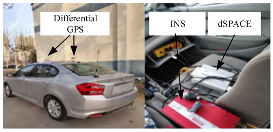
Figure 2.
Experimental equipment.
Data Collection Process and Methodology
- (1)
- Pre-Experimental Setup
The GPS antenna was mounted on top of the car to ensure that it was clearly visible to the satellite for accurate signal reception. The RT2500 INS was initialized and calibrated according to the manufacturer’s instructions to ensure accurate initial readings. The GPS and the INS converted the collected signals into CAN signals and transmitted them to control desk PC software on the through Auto box. The software application then analyzed the collected GPS and INS CAN signals by calling the compiled MATLAB program.
- (2)
- Data Collection During Experiment
As the vehicle moved, the INS continuously collected acceleration and angular rate data to track the vehicle’s motion. Simultaneously, the non-differential GPS collected position and speed data at regular intervals, which were transmitted to the MATLAB environment through Auto box. We used MATLAB to build the algorithm model, and the output of the system included information such as the longitude, latitude and heading angle of the vehicle. To verify the validity of the proposed method, we selected a rectangular road in China. As shown in Figure 3, we marked the shape of the road on Google Maps. In order to distinguish the robustness of the algorithm, we applied electromagnetic interference at a certain point in the road.
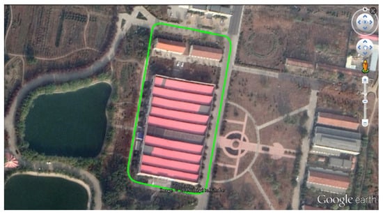
Figure 3.
The Google map of the experimental road.
Figure 4, Figure 5 and Figure 6 present the acceleration data recorded with the IMU, detailing the movement along the three axes. Figure 7, Figure 8 and Figure 9 display the angular velocity data for the corresponding axes of the gyroscope. The collected data encompassed actual measurements, superimposed white noise and accumulated drift, all of which contribute to a reduction in precision in inertial navigation. We fed these unprocessed readings to our algorithmic model, which processed them to determine velocity and location information.
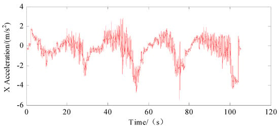
Figure 4.
Acceleration on X-axis of IMU.
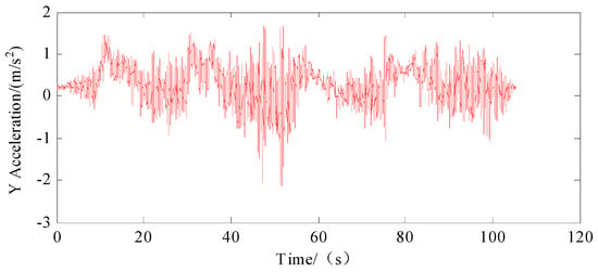
Figure 5.
Acceleration on Y-axis of IMU.
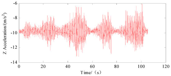
Figure 6.
Acceleration on Z-axis of IMU.
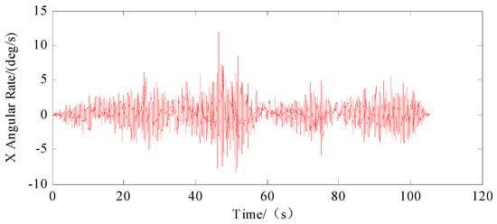
Figure 7.
Angular rate on X-axis of IMU.
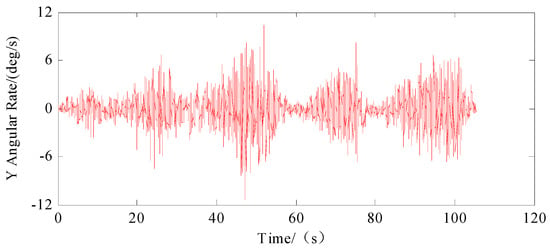
Figure 8.
Angular rate on Y-axis of IMU.
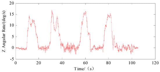
Figure 9.
Angular rate on Z-axis of IMU.
In our analysis, the X, Y and Z axes were designated as representing the transverse, longitudinal and vertical dimensions, respectively. Figure 4 illustrates the side-to-side or lateral acceleration experienced by the vehicle. Conversely, Figure 9 captures the vehicle’s rotational movements around the vertical axis and its yawing maneuvers. The prominent spikes observable in both Figure 4 and Figure 9 serve as indicators of the vehicle turning around four distinct corners, highlighting the dynamic nature of its trajectory.
We chose the differential GPS as the positioning reference curve. As shown in Figure 10, we parsed the raw data from the non-differential GPS and IMU outputs. Then, the three sets of data were compared in the same coordinate system. The horizontal coordinate was latitude and the vertical one longitude. As can be seen from the figure, the GPS’s positioning accuracy is high. However, within the region formed by the longitude of 116.0002 to 116.0005 and the latitude of 36.432 to 36.4325, the GPS data are distorted by interference. Due to the accumulated errors in the inertial navigation system, the positioning errors are gradually amplified.
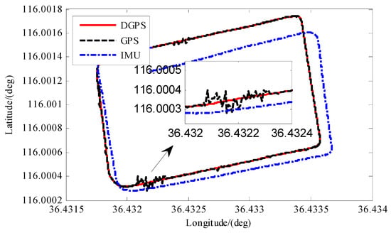
Figure 10.
The tracks of different navigation systems.
As shown in Figure 11, we further took the differential GPS as the benchmark and compared the final effect of the KF algorithm and the APF-IKF algorithm in the same coordinate system. In the figure, we can see that in the region where the GPS is not disturbed, the positioning curve analyzed by the KF algorithm deviates from the reference curve, but the positioning error is relatively small. After the GPS is subjected to interference, the location data analyzed by the KF algorithm are affected by the distortion of the GPS data. Therefore, the robustness of the KF algorithm is poor. In contrast, the data analyzed by the APF-IKF algorithm are consistent with the reference curve of the differential GPS output. In the area of GPS interference, the APF-IKF algorithm can accurately estimate the error and compensate for the navigation system’s shortcomings.
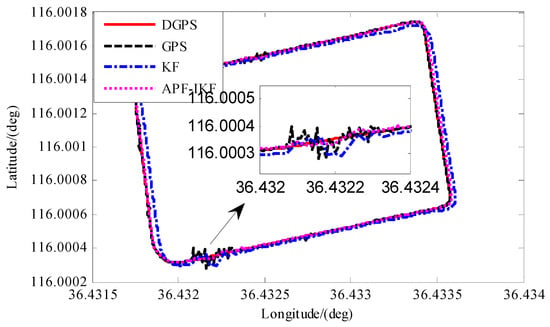
Figure 11.
Comparison of tracks between different algorithms.
The experimental validation confirmed the effectiveness and superiority of the APF-IKF algorithm within the context of integrated navigation systems. Figure 12 and Figure 13 clearly demonstrate that APF-IKF surpasses traditional methods by delivering enhanced accuracy and robustness against external interferences in the determination of course angles and speeds. The velocity errors analyzed with the APF-IKF algorithm were roughly between −0.2 km/h and 0.2 km/h and were all close to the zero line. The KF algorithm was affected by the cumulative error of the IMU, and the maximum value was 0.6° km/h. The APF-IKF algorithm exhibited superior estimation and analytical capabilities for velocity and heading angle errors compared with the conventional Kalman filter (KF) approach. The maximum error of vehicle heading angle determined by the KF algorithm was four times that of the APF-IKF algorithm. Notably, as time progressed, the error trend associated with APF-IKF remained closely clustered around zero, indicating a high degree of stability and consistency in its performance.
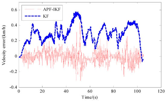
Figure 12.
Comparison of velocity error between different algorithms.
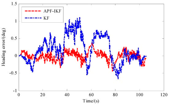
Figure 13.
Comparison of heading angle error between different algorithms.
Figure 14 and Figure 15 present the heading angle data and the eastward and northward velocity, respectively, processed by the APF-IKF algorithm. During the real-vehicle test, the vehicle navigated in a counterclockwise direction to complete a full loop. Observations from Figure 14 indicate that the vehicle’s heading angle remained relatively constant for the initial 10 s, signifying straight-line travel. Between the 32nd and 40th seconds, there was a gradual increase in the vehicle’s heading angle to 360 degrees, followed by an abrupt shift to 0 degrees. This transition corresponds to the vehicle maneuvering from the northerly to the southerly direction, then the westerly direction and finally the easterly direction. The vehicle completed a circuit and returned to the starting point, with the heading angle at the end aligning closely with that at the outset. The heading angle is a pivotal parameter in trajectory tracking control in autonomous vehicles. Figure 15 depicts the calculations of the vehicle’s lateral and longitudinal speeds based on the APF-IKF algorithm. Within the first 10 s, both the eastward and northward velocities were negative, indicating southwestward motion. These velocity metrics are critical to characterizing the operational stability of an autonomous vehicle, which is vital to studying decision making and dynamic stability in intelligent vehicle systems.
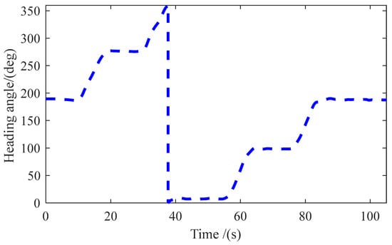
Figure 14.
The heading angle information of APF-IKF.
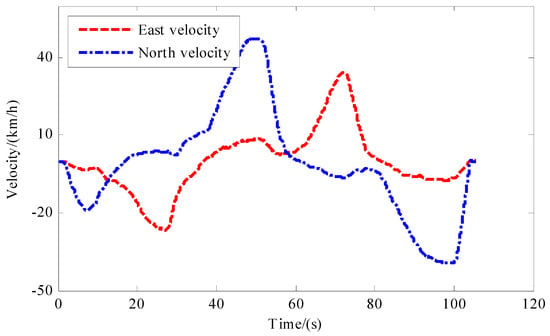
Figure 15.
The eastward velocity and northward velocity of APF–IKF.
To further validate the system’s performance, we conducted a series of experiments using actual vehicles, during which we arranged a cluster of GPS units to intentionally lose signal at a predetermined time.
Figure 16 illustrates the comparison between the latitude and longitude estimated by the proposed algorithm and the actual coordinates during sudden GPS interruption. Figure 17 presents a comparison between the plane coordinate curve generated by the proposed algorithm and the target coordinate curve under sudden GPS interruption. The figures reveal that at approximately 36.4509 degrees latitude, a disruption in GPS signal occurs, leading to significant deviations in the output latitude and longitude values from their actual counterparts. Additionally, Figure 17 indicates an abrupt failure of GPS at a northward distance of 140 m, corresponding to Figure 16. Subsequently, a consistent error of about 20 cm is maintained by the system. Prior to signal interruption, the system error remains below 10 cm.
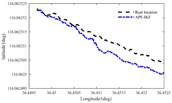
Figure 16.
Comparison of latitude and longitude mapping following sudden GPS disruption.
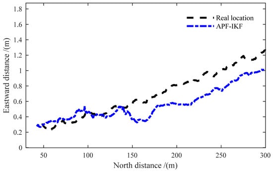
Figure 17.
A comparative analysis of spatial coordinates following an abrupt disruption in GPS navigation.
5. Conclusions
Traditional filtering approaches fall short in adequately addressing the intricacies of integrated GPSs/INSs characterized by uncertain dynamic models. The incorporation of auxiliary particle filtering offers a significant advantage thanks to its dual weighting mechanism, which demonstrates superiority in managing non-Gaussian noise and consequently leads to more precise estimation outcomes.
In this study, we developed a novel approach that integrates a particle filter with a Kalman filter to bolster the system’s resilience against non-Gaussian noise. A dedicated real-vehicle experimental setup was established to rigorously validate the proposed algorithm. By leveraging differential GPS data, a comparative analysis was conducted to assess the robustness of the GPS/INS navigation system under GPS signal disruption. A comparison was made between the APF-IKF and the conventional Kalman filter (KF) algorithms. The results underscore a substantial enhancement in the system’s anti-interference capabilities without compromising on accuracy.
Moreover, the benefits of the APF-IKF-based integrated navigation system were further substantiated by a meticulous comparison against other systems in terms of longitudinal, latitudinal and vehicular speed parameters along the driving route.
In the process of path-tracking control in autonomous vehicles, the most important parameters applied are the northward and eastward speed, the position data and the vehicle heading angle. These data are precisely output by the APF-IKF integrated navigation system.
Author Contributions
Supervision, H.X. and D.G.; conceptualization, H.X.; methodology, H.X. and D.G.; software, H.X.; validation, Z.F. and M.C.; formal analysis, D.W.; investigation, H.X.; resources, M.C. and H.X.; data curation, D.G. and H.X.; writing—original draft preparation, H.X.; writing—review and editing, D.G. and Z.F. All authors have read and agreed to the published version of the manuscript.
Funding
This research study received no external funding.
Data Availability Statement
Data are available upon request from the authors. The data that support the findings of this study are available from the corresponding author, D.G., upon reasonable request.
Conflicts of Interest
The authors declare no conflicts of interest.
References
- Zhang, K.; Gui, H.; Luo, Z.; Li, D. Matching for navigation map building for automated guided robot based on laser navigation without a reflector. Ind. Robot 2019, 46, 17–30. [Google Scholar] [CrossRef]
- Hiroki, K.; Masaki, O.; Takeshi, N.; Takeshi, Y.; Takanori, F. Localization Method Using Camera and LiDAR and its Application to Autonomous Mowing in Orchards. Jrobomech 2022, 34, 877–886. [Google Scholar]
- Zeng, Q.; Kan, Y.; Tao, X.; Hu, Y. LiDAR Positioning Algorithm Based on ICP and Artificial Landmarks Assistance. Sensors 2021, 21, 7141. [Google Scholar] [CrossRef] [PubMed]
- Li, B.; Chen, G. Improving the combined GNSS/INS positioning by using tightly integrated RTK. GPS Solut. 2022, 26, 144. [Google Scholar] [CrossRef]
- Liang, W.; Li, K.; Li, Q. Anti-spoofing Kalman filter for GPS/rotational INS integration. Measurement 2022, 193, 110962. [Google Scholar] [CrossRef]
- Rahmad, S.; Mohamed, A.; Abdenour, H.; Atika, R.; Abdelmalik, T.-A. Map-Matching-Based Localization Using Camera and Low-Cost GPS For Lane-Level Accuracy. Procedia Comput. Sci. 2022, 198, 255–262. [Google Scholar]
- Andrzej, S.; Witold, K.; Pawel, B. Sensors and System for Vehicle Navigation. Sensors 2022, 22, 1723. [Google Scholar] [CrossRef] [PubMed]
- Liu, C. Research on GPS Vehicle Navigation System Based on Embedded Technology. J. Phys. Conf. Ser. 2022, 2170, 012045. [Google Scholar] [CrossRef]
- Sun, J.; Tao, L.; Niu, Z.; Zhu, B. An Improved Adaptive Unscented Kalman Filter with Application In the Deeply Integrated Bds/ins Navigation System. IEEE Access 2020, 8, 95321–95332. [Google Scholar] [CrossRef]
- Liang, J.; Li, Y.; Yin, G.; Xu, L.; Lu, Y.; Feng, J.; Shen, T.; Cai, G. A MAS-based hierarchical architecture for the cooperation control of connected and automated vehicles. IEEE Trans. Veh. Technol. 2022, 72, 1559–1573. [Google Scholar] [CrossRef]
- Mihajlow, R.P.; Demirev, V.G. Application of GPS navigation in agricultural aggregates. Annu. J. Tech. Univ. Varna Bulg. 2018, 2, 14–19. [Google Scholar] [CrossRef]
- Kamil, K.; Damian, W. New Methodology for Computing the Aircraft’s Position Based on the PPP Method in GPS and GLONASS Systems. Energies 2021, 14, 2525. [Google Scholar] [CrossRef]
- Kumar, P.S.; Dutt, V.S.I. Development and performance evaluation of Correntropy Kalman Filter for improved accuracy of GPS position estimation. Int. J. Intell. Netw. 2022, 3, 1–8. [Google Scholar]
- Zhu, W.; Hou, J.; Liu, Z.; Ding, Z. GPS Positioning Error Compensation Based on Kalman Filtering. J. Phys. Conf. Ser. 2021, 1920, 012088. [Google Scholar] [CrossRef]
- Xu, X. A design of intelligent delivery drone based on BeiDou navigation and visual processing. J. Phys. Conf. Ser. 2021, 1976, 012035. [Google Scholar] [CrossRef]
- Ahmed, E.M.; Ahmed, A.; Ahmed, E.A.; Ashraf, A. A Machine Learning Approach for an Improved Inertial Navigation System Solution. Sensors 2022, 22, 1687. [Google Scholar] [CrossRef] [PubMed]
- Alexander, M.; Boris, M.; Gregory, M. Navigation of Underwater Drones and Integration of Acoustic Sensing with Onboard Inertial Navigation System. Drones 2021, 5, 83. [Google Scholar] [CrossRef]
- Wu, G.; Fang, X.; Song, Y.; Liang, M.; Chen, N. Study on the Shearer Attitude Sensing Error Compensation Method Based on Strapdown Inertial Navigation System. Appl. Sci. 2022, 12, 10848. [Google Scholar] [CrossRef]
- Ban, J.; Wang, L.; Chen, G. A Platform Control Algorithm for Long-endurance Hybrid Inertial Navigation System with Fiber Optic Gyroscope. Instrum. Exp. Tech. 2022, 65, 645–652. [Google Scholar] [CrossRef]
- Wu, L.; Sun, Y.; Fu, X.; Zeng, Q. A novel ambiguity resolution model of BeiDou navigation satellite system/inertial navigation system tightly coupled for kinematic-to-kinematic precise relative positioning. Int. J. Distrib. Sens. Netw. 2022, 18. [Google Scholar] [CrossRef]
- Liang, J.; Lu, Y.; Wang, F.; Yin, G.; Zhu, X.; Li, Y. A robust dynamic game-based control framework for integrated torque vectoring and active front-wheel steering system. IEEE Trans. Intell. Transp. Syst. 2023, 24, 7328–7341. [Google Scholar] [CrossRef]
- Liang, J.; Wang, F.; Feng, J.; Zhao, M.; Fang, R.; Pi, D.; Yin, G. A Hierarchical Control of Independently Driven Electric Vehicles Considering Handling Stability and Energy Conservation. IEEE Trans. Intell. Veh. 2023, 9, 738–751. [Google Scholar] [CrossRef]
- Liang, J.; Tian, Q.; Feng, J.; Pi, D.; Yin, G. A polytopic model-based robust predictive control scheme for path tracking of autonomous vehicles. IEEE Trans. Intell. Veh. 2023, 9, 3928–3939. [Google Scholar] [CrossRef]
- Dadashi, F.; Millet, G.P.; Aminian, K. A Bayesian approach for pervasive estimation of breaststroke velocity using a wearable IMU. Pervasive Mob. Comput. 2015, 19, 37–46. [Google Scholar] [CrossRef]
- Shaghaghian, A.; Karimaghaee, P. Improving GPS/INS Integration Using FIKF-Filtered Innovation Kalman Filter. Asian J. Control 2019, 21, 1671–1680. [Google Scholar] [CrossRef]
- Chen, Y.; Ling, X.; Li, Y.; Jiao, H.; Liu, Y. Study on GPS/INS Loose and Tight Coupling. In Proceedings of the 2015 7th International Conference on Intelligent Human-Machine Systems and Cybernetics, Hangzhou, China, 26–27 August 2015; IEEE: Piscataway, NJ, USA, 2015; Volume 1, pp. 34–37. [Google Scholar]
- Wang, R. IMM-EKF Based GPS/INS Combined Positioning Method for Drone. In Proceedings of the 2020 International Conference on Computing and Data Science (CONF-CDS 2020), Stanford, CA, USA, 1–2 August 2020; pp. 172–176. [Google Scholar] [CrossRef]
- Jiang, H.; Shi, C.; Li, T.; Dong, Y.; Li, Y.; Jing, G. Low-cost GPS/INS integratio n with accurate measurement modeling using an extended state observer. GPS Solut. 2020, 25, 17. [Google Scholar] [CrossRef]
- Ryu, K.; Kang, J.; Lee, D. Performance Comparison between EKF and UKF in GPS/INS Low Observability Conditions. In Proceedings of the 2021 21st International Conference on Control, Automation and Systems (ICCAS), Jeju, Republic of Korea, 12–15 October 2021. [Google Scholar]
- Zhang, G.; Hsu, L.-T. Intelligent GNSS/INS integrated navigation system for a commercial UAV flight control system. Aerosp. Sci. Technol. 2018, 80, 368–380. [Google Scholar] [CrossRef]
- Liu, Y.; Fan, X.; Lv, C.; Wu, J.; Li, L.; Ding, D. An innovative information fusion method with adaptive Kalman filter for integrated INS/GPS navigation of autonomous vehicles. Mech. Syst. Signal Process. 2018, 100, 605–616. [Google Scholar] [CrossRef]
- Zhang, C.; Guo, C.; Zhang, D. Ship navigation via GPS/IMU/LOG integration using adaptive fission particle filter. Ocean Eng. 2018, 156, 435–445. [Google Scholar] [CrossRef]
- Liang, J.; Feng, J.; Fang, Z.; Lu, Y.; Yin, G.; Mao, X.; Wu, J.; Wang, F. An Energy-oriented Torque-vector Control Framework for Distributed Drive Electric Vehicles. IEEE Trans. Transp. Electrif. 2023, 9, 4014–4031. [Google Scholar] [CrossRef]
Disclaimer/Publisher’s Note: The statements, opinions and data contained in all publications are solely those of the individual author(s) and contributor(s) and not of MDPI and/or the editor(s). MDPI and/or the editor(s) disclaim responsibility for any injury to people or property resulting from any ideas, methods, instructions or products referred to in the content. |
© 2024 by the authors. Licensee MDPI, Basel, Switzerland. This article is an open access article distributed under the terms and conditions of the Creative Commons Attribution (CC BY) license (https://creativecommons.org/licenses/by/4.0/).
