Next Article in Journal
Impact of Double-Suction Pump Eye Diameter Variation on Cavitation Phenomena
Previous Article in Journal
A Literature Review of Fault Detection and Diagnostic Methods in Three-Phase Voltage-Source Inverters
 
 
Correction published on 2 December 2024, see Machines 2024, 12(12), 874.
Article

A Closed-Form Inverse Kinematic Analytical Method for Seven-DOF Space Manipulator with Aspheric Wrist Structure

by
Guojun Zhao
1,*,
Bo Tao
2,†,
Du Jiang
1,†,
Juntong Yun
1,† and
Hanwen Fan
1,†
1
Key Laboratory of Metallurgical Equipment and Control Technology of Ministry of Education, Wuhan University of Science and Technology, Wuhan 430081, China
2
Precision Manufacturing Research Institute, Wuhan University of Science and Technology, Wuhan 430081, China
*
Author to whom correspondence should be addressed.
These authors contributed equally to this work.
Machines 2024, 12(9), 632; https://doi.org/10.3390/machines12090632
Submission received: 5 August 2024 / Revised: 5 September 2024 / Accepted: 6 September 2024 / Published: 9 September 2024 / Corrected: 2 December 2024
(This article belongs to the Section Machine Design and Theory)

Abstract

:
The seven-degree-of-freedom space manipulator, characterized by its redundant and aspheric wrist structure, is extensively used in space missions due to its exceptional dexterity and multi-joint capabilities. However, the non-spherical wrist structure presents challenges in solving inverse kinematics, as it cannot decouple joints using the Pieper criterion, unlike spherical wrist structures. To address this issue, this paper presents a closed-form analytical method for solving the inverse kinematics of seven-degree-of-freedom aspheric wrist space manipulators. The method begins by identifying the redundant joint through comparing the volumes of the workspace with different joints fixed. The redundant joint angle is then treated as a parametric joint angle, enabling the derivation of closed-form expressions for the non-parametric joint angles using screw theory. The optimal solution branch is identified through a comparative analysis of various self-motion manifold branches. Additionally, a hybrid approach, combining analytical and numerical methods, is proposed to optimize the parametric joint angle for a trajectory tracking task. Simulation results confirm the effectiveness of the proposed method.

1. Introduction

Industrial seven-degree-of-freedom (DOF) robots have gained widespread attention in modern space exploration [1]. The high dexterity and multi-joint structure of these space manipulators enable them to perform various space missions, such as satellite maintenance [2], space station construction [3], and planetary exploration [4]. In this context, research on inverse kinematics (IKs) for seven-DOF space manipulators is particularly critical [5]. The IK solutions provide the necessary theoretical foundation for the precise operation of these manipulators in complex space environments, which is crucial for improving their kinematic accuracy and efficiency [6,7].
The current methods for solving the inverse kinematics of manipulators are mainly divided into two types: the analytical method and the numerical method [8,9,10,11]. Analytical methods, such as geometric and algebraic approaches, can yield mathematical expressions for all joint angles of manipulators, offering precise inverse kinematics solutions [12]. However, as the DOF of the manipulator increases, implementing analytical methods becomes increasingly challenging [13,14]. Numerical methods are commonly employed due to their notable approximations and adaptability to various manipulator structures [15,16]. Nevertheless, they have a significant drawback related to singularities. These methods require obtaining the joint configuration based on the inverse Jacobian [17]. Furthermore, specific joint configurations can lead to a singular Jacobian, which may result in impractical joint velocities [18]. Given the limitations of analytical and numerical methods, hybrid methods, which combine the advantages of both, are recommended. These methods balance computational accuracy and efficiency and are suitable for solving the inverse kinematics problem of complex robotic manipulators [19].
Parameterization of one or multiple joint angles is currently the most widely used hybrid method. When the parameter joint angle belongs to an internal joint of the redundant manipulator, the critical step is to identify the redundant joint. Kuhlemann proposed that an appropriate method for selecting redundant joints not only enhances the convenience of the solution process but also improves the quality of the IK solution [20]. Lee demonstrated that the quality of the IK solution is highly dependent on the selection of redundant joints [21]. They determine the redundant joints of manipulators by analyzing the impact of joint angles on the global configuration and the range of the null space, respectively. Zaplana proposed a method for selecting redundant joints by analyzing the workspace of the manipulator [22]. Once the redundant joint is determined, the next step is to solve the inverse kinematics of the manipulator based on the parametric joint angle. Zaplana and Tondu proposed utilizing joint variables as redundant parameters to derive closed-form solutions for IKs [23]. These methods effectively mitigate the impact of additional DOF. There has also been some research on parametric joint angles that do not belong to the internal joint of a redundant manipulator. Shimizu and Dou et al. introduced the concept of an “arm angle” and used it as the parametric joint angle to solve the inverse kinematics of a redundant manipulator [24,25]. This method omits the step of determining the redundant joint. However, the process of determining the arm angle is quite complicated. Moreover, this method is generally applicable to spherical wrist manipulators but not to non-spherical wrist manipulators.
Self-motion manifolds encompass all inverse kinematics solutions of manipulators. Analyzing the performance of manipulators based on self-motion manifolds offers a global perspective. Furthermore, applying self-motion manifolds to the motion planning of manipulators is significant as it enhances motion performance and ensures the continuity of joint trajectories [26]. Vahrenkamp achieved obstacle avoidance in manipulator motion planning by applying self-motion manifolds to inverse kinematics optimization at the positional level [27]. Ananthanarayanan proposed a motion planning method to guarantee the smoothness and continuity of joint trajectories based on the manifold indicator of self-motion manifolds [28].
In previous works, Xiao [29] split a 6DOF non-spherical wrist manipulator into two sub-chains and achieved the parametric solution of the manipulator by comparing the position and orientation of the two sub-chains. Zhang [30] investigated a 6DOF non-spinning surface manipulator based on the work in [29] and proposed a more simplified objective function consisting of multiple variables. This function was based on the method outlined in [29]. Subsequently, the selection of multiple solutions for inverse kinematics was realized by dividing the unique domain of the manipulator. Unlike previous works, this paper shifts the research focus from a 6DOF manipulator to a 7DOF manipulator, rendering some methods applicable to the 6DOF manipulator no longer suitable for the 7DOF manipulator. The main improvements of this paper compared to previous works are outlined as follows.
  • The number of joint angles to be optimized has been reduced from multiple to one, which decreases the complexity of the objective function by lowering the number of optimization dimensions;
  • Screw theory is no longer limited to modeling but is now applied to inverse kinematics solving as well;
  • The smoothing of joint angles for the manipulator during trajectory tracking has been considered, and a method has been proposed to improve it.
Since a non-spherical wrist 7DOF manipulator cannot decouple the joints according to the Pieper criterion like a spherical wrist manipulator, this leads to difficulties in obtaining the inverse kinematics solution. To address the inverse kinematics solution problem of a non-spherical wrist 7DOF manipulator, this paper proposes a closed-form inverse kinematics analysis method based on the joint redundancy parameter. This method determines the optimal inverse kinematics solution by selecting the redundant joint, deriving analytical expressions for the non-redundant joint angles based on the redundant joint angle, identifying the optimal solution branch, and optimizing the parametric joint angle based on a trajectory tracking task. The primary contributions of this paper are as follows:
  • Applying established criteria for identifying the redundant joint in an aspheric wrist redundant manipulator based on workspace analysis;
  • An optimal solution branch selection method based on self-motion manifolds is proposed;
  • A hybrid method based on screw theory for solving the inverse kinematics of a space manipulator is proposed.
The rest of this paper is organized as follows. Section 2 models the forward kinematics of the space manipulator. Section 3 introduces a workspace analysis method for determining the redundant joint of the space manipulator. Section 4 derives analytic expressions for non-parametric joint angles based on the parametric joint angles. Section 5 determines the optimal solution branch based on self-motion manifolds and presents a hybrid method to determine the optimal parametric joint angle based on the trajectory tracking task. Section 6 provides simulations and discussion. The final section concludes this paper.

2. Forward Kinematic Analysis of a Space Manipulator

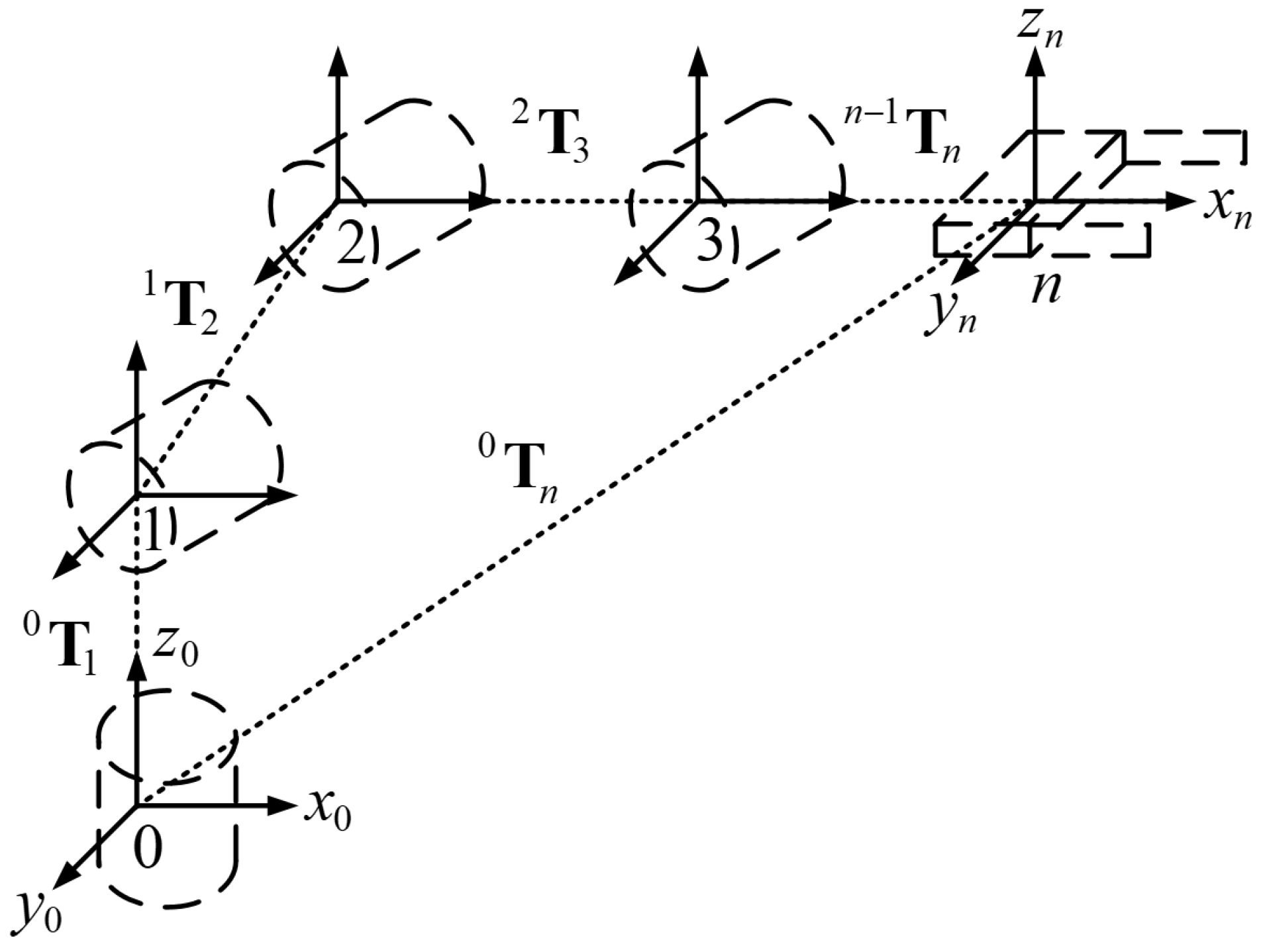
Robotic manipulators typically consist of links connected by joints, forming open kinematic chains. The final component within this kinematic chain is referred to as the end effector (EE). Each joint is linked to an articulation, collectively defining the joint configuration θ = [ θ 1 θ 2 θ 3 . . . θ n ] T , where n represents the overall DOF of the manipulator, as illustrated in Figure 1.
Figure 1 shows a kinematic chain of a serial robotic manipulator. j−1Tj represents the homogeneous transformation matrix of link j to link j − 1.
Forward kinematics involves calculating the position and orientation of the end effector based on the joint configuration. It is typically a straightforward problem with a guaranteed solution. The expression for forward kinematics is shown in Equation (1).
T n 0 ( θ ) = T 1 0 ( θ 1 ) 1 T 2 ( θ 2 ) n 1 T n ( θ n ) T n 0 ( θ ) = j = 1 n T j j 1 ( θ j )
where T n 0 represents the pose transformation matrix of end effector with respect to base coordinate system. θ represents the joint vector [ θ 1, θ 2,..., θ 7]. j−1Tj represents the homogeneous transformation matrix of link j to link j−1. θ j represents the j-th joint angle. n represents the total number of degrees of freedom.
In this section, a seven-DOF space manipulator with a non-spherical wrist structure is studied, and forward kinematic analysis is performed based on screw theory. Compared with the Denavit–Hartenberg (DH) method [31], the screw theory method is more flexible, requiring only two coordinate systems: the base coordinate system and the tool coordinate system. By describing the motion of the manipulator as a whole, this approach simplifies the analysis of the mechanism [32,33,34,35]. In Section 4, screw theory is utilized to derive the inverse kinematic solution of the manipulator. This theory has two key properties: (1) parallel vectors maintain the same direction when rotating around an axis; and (2) when a point rotates about an axis, its projection remains consistent in different directions. These properties facilitate the derivation of analytical expressions for non-parametric joint angles in relation to the parametric joint angle.
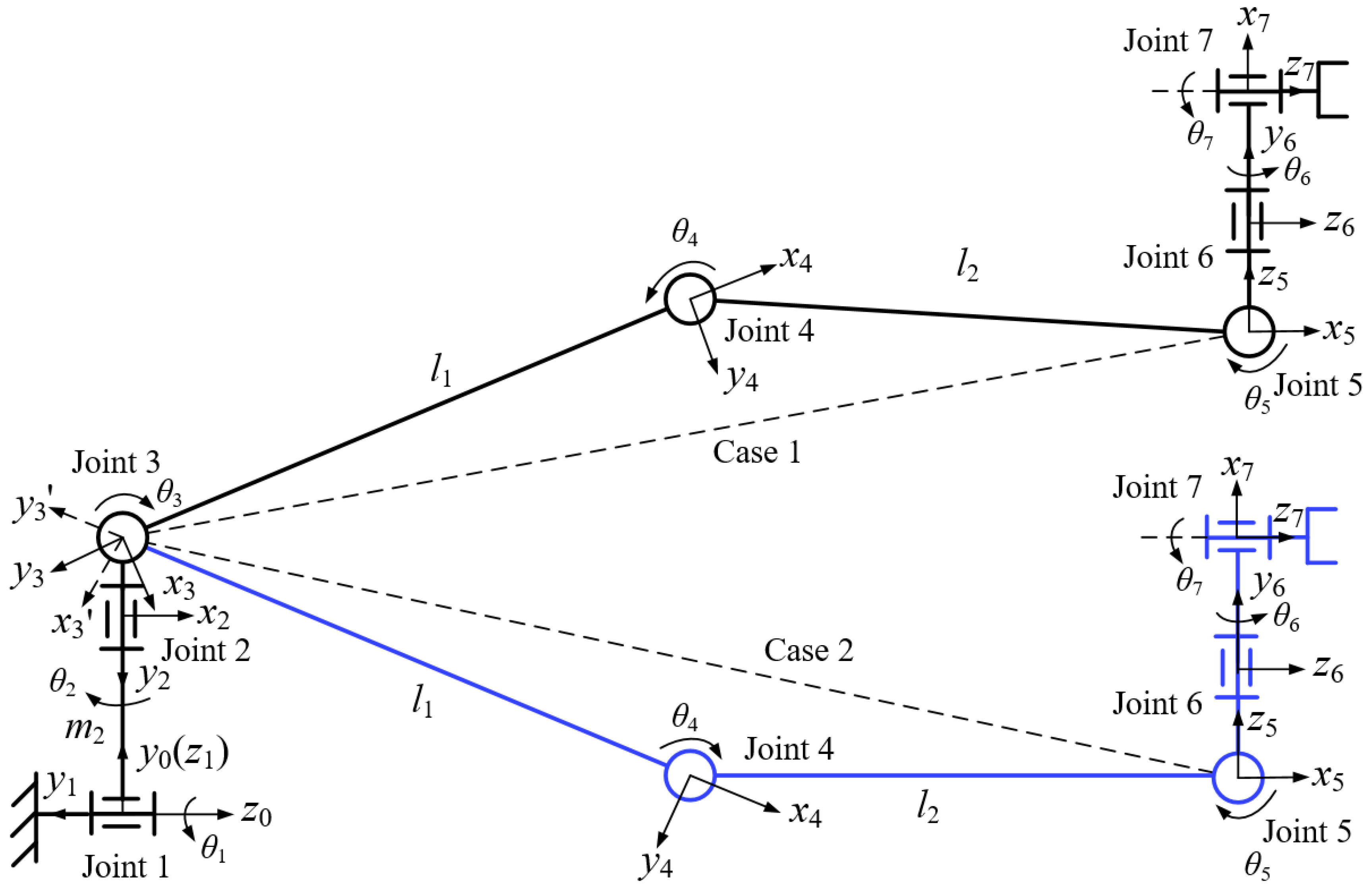
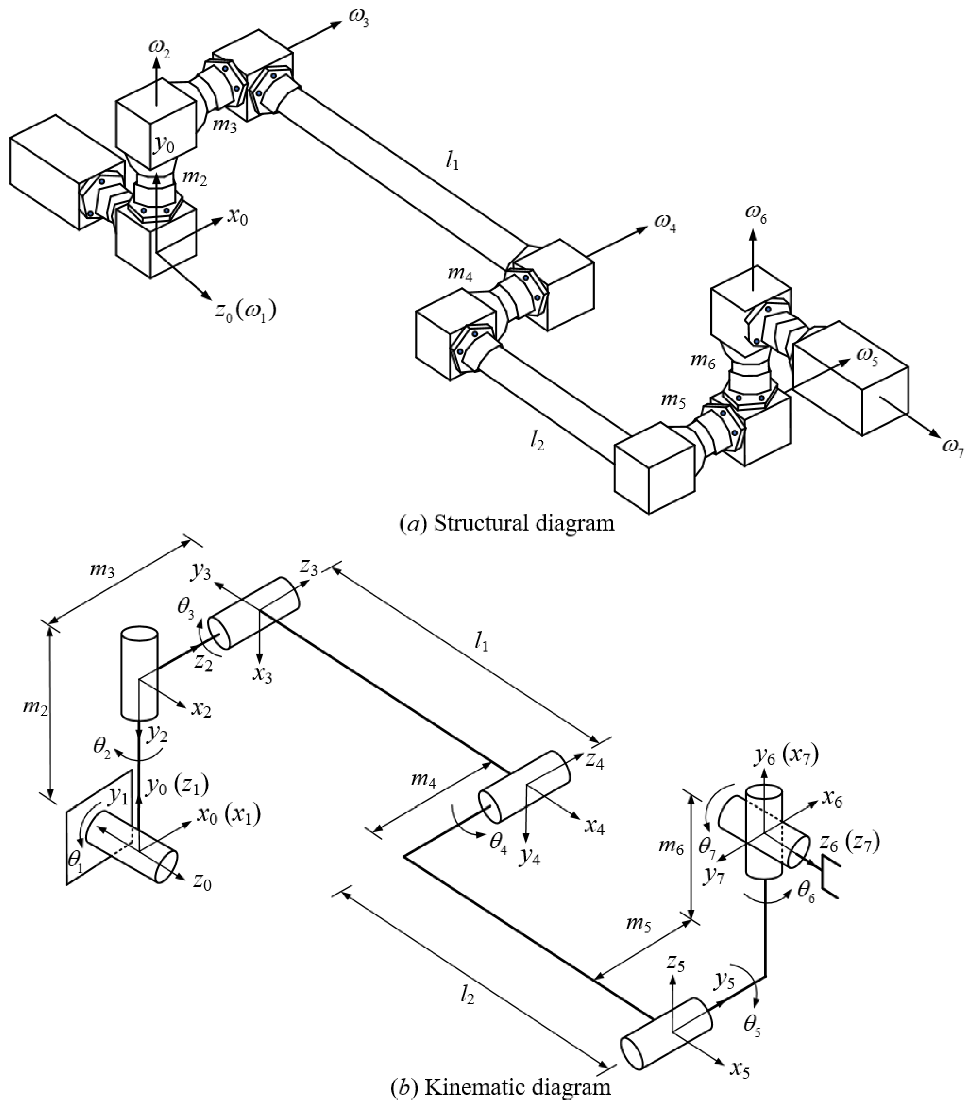
Figure 2 shows the structural diagram (Figure 2a) and kinematic diagram (Figure 2b) of the seven-DOF space manipulator. According to Figure 2, it is evident that the third, fourth, and fifth joint axes of the manipulator are parallel to each other. Based on the property that the direction of vector rotation around parallel axes and the projection of point rotation around parallel axes are invariant, the forward kinematic expression of the manipulator can be simplified. The specific derivation process for the inverse kinematics will be described in Section 4.
Table 1 shows the joint parameters of seven-DOF space manipulator based on screw theory. Where i represents the i-th joint. ω i represents the unit vector of the i-th joint axis. λ i represents the point on the i-th joint axis. Based on screw theory, the pose of the rigid body in space can be represented by the relative pose of the coordinate system fixed on the rigid body to the world coordinate system. The mathematical expression for a pose change of the rigid body is shown in Equation (2).
SE ( 3 ) = R p 0 1 R R 3 × 3 , p R 3 , R T R = I , d e t ( R ) = 1
where SE(3) is the special Euclidean group, which also represents the pose transformation matrix of rigid body. R is a 3 × 3 orthogonal matrix, representing the orientation change of the rigid body. p is a 3 × 1 position vector, representing the position change of the rigid body. For SE(3), the Lie algebra is se(3), and the elements of this Lie algebra are defined as shown in Equation (3).
ξ ^ = ω ^ ν 0 0
where ξ ^ represents the unit kinematic screw matrix, ω ^ represents the unit angular velocity of rigid body, and ν represents the translational velocity of rigid body. According to screw theory, the screw motion of the manipulator can be expressed in the form of exponential coordinates of the kinematic screw, which is shown in Equation (4).
e ξ ^ θ = e ω ^ θ ( I e ω ^ θ ) ( ω × ν ) + θ ω ω T ν 0 1 , ω 0 I θ ν 0 1 , ω = 0
where θ represents the joint angle, I represents the 3 × 3 identity matrix, and ω represents the angular velocity of rigid body. e ξ ^ θ represents the pose matrix transformed from the joint coordinate system to world coordinate system. e ω ^ θ represents the 3 × 3 orientation matrix, and (Ie ω ^ θ ) ( ω × ν ) + θ ω ω T ν represents the 3 × 1 position vector. The forward kinematic expression obtained based on screw theory is shown in Equation (5).
T = e ξ ^ 1 θ 1 e ξ ^ 2 θ 2 e ξ ^ 3 θ 3 e ξ ^ 4 θ 4 e ξ ^ 5 θ 5 e ξ ^ 6 θ 6 e ξ ^ 7 θ 7 T 0
where ξ ^ i represents the unit kinematic screw matrix of the i-th joint and θ i represents the i-th joint angle. T represents the pose change matrix of the end effector with respect to the base coordinate system. e ξ ^ i θ i represents the pose change matrix of joint i relative to the base coordinate system. T0 represents the initial pose matrix of the end effector.

3. Determination of a Redundant Joint

The redundant degree of freedom provides the manipulator with greater maneuverability and singularity avoidance capabilities, but it also introduces a redundant kinematic parameter. To handle this redundant kinematic parameter, the paper first identifies it by analyzing and comparing the workspace after fixing different joint angles to determine the redundant joint. Then, the redundant joint angle is treated as the redundant kinematic parameter, and analytical expressions are derived for the non-redundant joint angles in terms of this parameter. Finally, a multi-objective optimization method is proposed to determine the optimal redundant parameter based on the trajectory tracking task.

3.1. Exclusion of Non-Redundant Joints

In this section, the method for excluding non-redundant joints builds upon the approach proposed in [22]. The method specifies the parameter to be optimized, which is a choice favoring the subsequent optimization. However, under different optimization goals, the proposed strategy might not be desirable or could be inferior to other constraints, such as intuitive behavior. Due to the additional DOF, obtaining closed-form inverse kinematics solutions for a redundant manipulator is challenging. By selecting and parameterizing the redundant joint angle, a redundant manipulator can be transformed into a non-redundant manipulator, which facilitates the process of solving the inverse kinematics. For simplicity, the following notations are defined:
(i)
W represents the workspace of the manipulator.
(ii)
Wi represents the working subspace of W when the i-th joint angle is set to a constant value.
To simplify the selection process of the redundant joint, non-redundant joints are excluded first. Joint i is considered to be a non-redundant joint when the following condition is satisfied:
  • When joint i is fixed, the manipulator becomes a globally degenerate manipulator.
A manipulator is globally degenerate if and only if, when one of the joint angles ( θ ( i ) , i = 1, 2, , 7) is fixed to a constant value C, the determinant of the Jacobian, (det(JG( θ )), equals 0.

3.2. Identification of Redundant Joint

In this section, the method for determining the redundant joint builds upon the approach proposed in [22]. After excluding non-redundant joints, the redundant joint can be determined based on candidate joints. The discriminating condition for the redundant joint is shown below:
  • There exists 2 i n such that Wi = W.
The condition indicates that there exists a redundant joint i for which Wi = W. The swept volume of Wi is obtained by fixing joint i and rotating around its axis. Since Wi is symmetric about the rotation axis, cross-sections can be used in place of the swept volume for comparison [36]. By setting the i-th joint angle θ i = 0, the cross-section SWi of the working subspace can be obtained. Subsequently, the area of SWi can be calculated using Equation (6). If the cross-sectional areas of W and Wi are similar, it indicates that joint i is redundant.
SW i = x m i n x m a x ( z 1 m a x ( x ) z 1 m i n ( x ) + . . . + z L m a x ( x ) z L m i n ( x ) ) Δ x
where SWi represents the projected area of the corresponding workspace in the x-z plane when the i-th joint is fixed. xmax and xmin represent the maximum and minimum values of SWi in the x-axis direction. z1max(x), , zLmin(x) represent the local extreme values of z for each x. Δ x represents the discrete step size in the x-direction. The pseudo-code for generating the workspace Wi is shown in Algorithm 1. The specific link parameters and the limits of each joint angle of the manipulator are shown in Table 2 and Table 3, respectively.
Algorithm 1 Workspace Generation
Require: 
Joint parameters JP (Table 1 and Table 2), Forward Kinematics function FK Equation (5),
(Equation (40)), Minimum value of the j-th joint angle θ jmin (Table 3), Maximum value
of the j-th joint angle θ jmax (Table 3).
Ensure: 
Workspaces Wi ( 1 i 7 )
1:
for  1 m 4000   do
2:
    the i-th joint angle θ i← 0
3:
    the j-th joint angle θ j θ jmin + rand(1)( θ jmax θ jmin) ( 1 j 7 , i j )
4:
    Pose matrix Tm ← FK(JP)
5:
    Position vector p mTm
6:
end for
7:
Wi p 1, , p 1000

3.3. Example Analysis

According to the condition in Section 3.1, when the fourth, fifth, and sixth joints are fixed, the manipulator becomes a globally degenerate manipulator. For this reason, joints 4, 5, and 6 are not redundant joints.
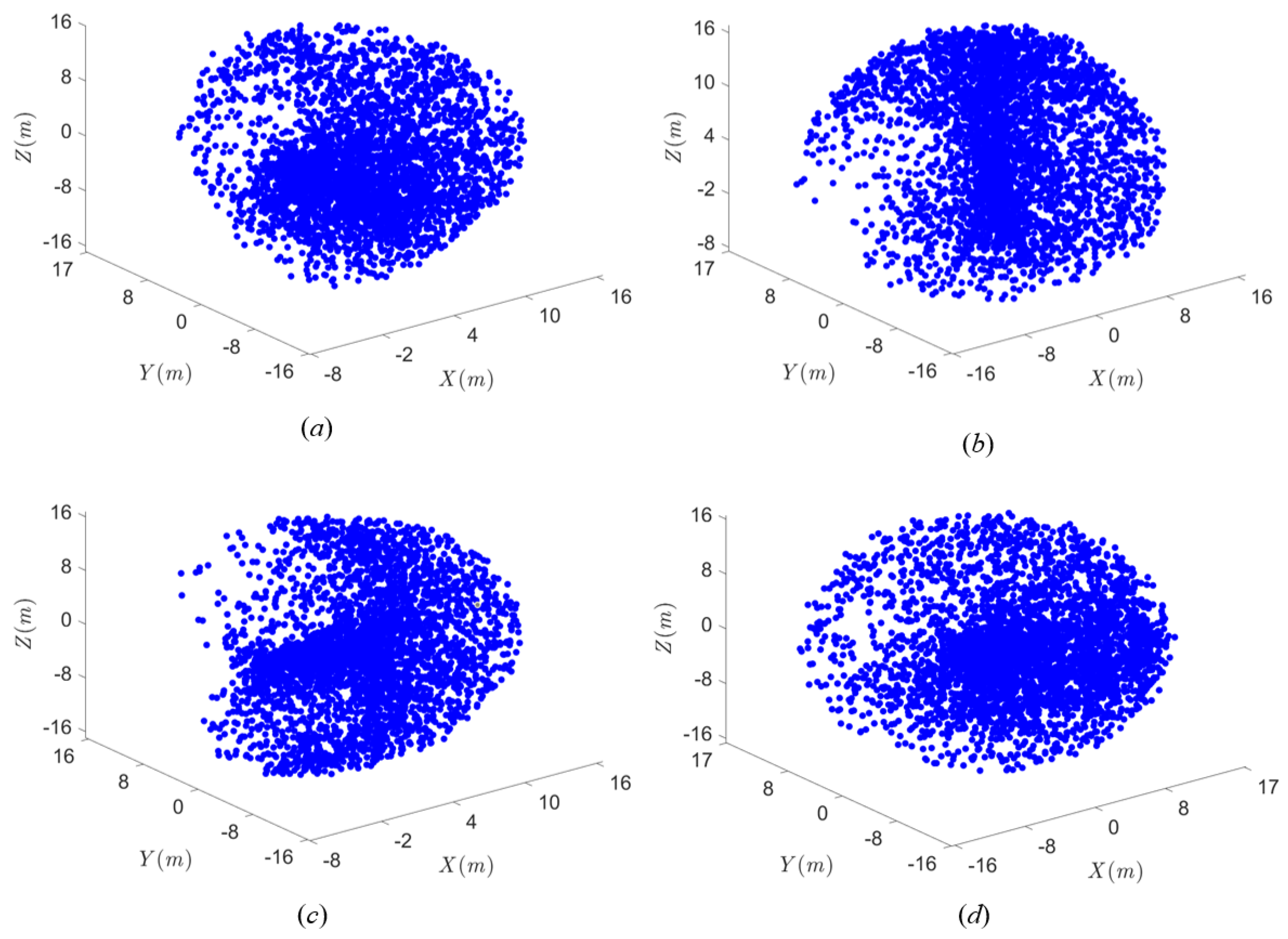
According to the condition in Section 3.2, the redundant joint can be determined by comparing the volumes of working subspaces with the first, second, third, and seventh joints fixed (Figure 3). According to Algorithm 1, the dimensions of different working subspaces along the x-axis, y-axis, and z-axis are as follows:
W 1 : 24 m × 33 m × 32 m W 2 : 32 m × 33 m × 24 m W 3 : 24 m × 32 m × 32 m W 7 : 33 m × 33 m × 32 m
W1, W2, W3, and W7 represent the workspaces with the first, second, third, and seventh joints fixed, respectively. When no joint is fixed, the dimensions of the original workspace W along the x-axis, y-axis, and z-axis are 33 m × 33 m × 32 m, which are the same as those of W7. Furthermore, according to Equation (6), the projection areas of the x-z cross-sections of W1, W2, W3, and W7 can be obtained and are shown as follows:
SW 1 : 540.4946 m 2 SW 2 : 633.5214 m 2 SW 3 : 643.7499 m 2 SW 7 : 786.4967 m 2
SW1, SW2, SW3, and SW7 represent the projection areas of the workspace in the x-z plane when the first, second, third, and seventh joints are fixed, respectively. The projection area of the original workspace in the x-z plane is known to be 786.4967 m2, which is consistent with SW7. For the above reasons, the seventh joint is considered the redundant joint, and the seventh joint angle is considered the parametric joint angle.
Figure 3a–d represent the corresponding workspaces of the manipulator when the first, second, third, and seventh joint angles are fixed to zero, respectively. When the i-th joint angle is fixed to a constant value, the corresponding workspace Wi is called the working subspace of original workspace W.

4. Inverse Kinematic Analysis

In this section, screw theory is used to solve the inverse kinematics of the manipulator. Based on screw theory and the parametric joint angle, expressions for the non-parametric joint angles are derived. The exact derivation of the non-parametric joint angles is provided below.
Shifting the terms of Equation (5), Equation (7) can be obtained.
e ξ ^ 3 θ 3 e ξ ^ 4 θ 4 e ξ ^ 5 θ 5 = e ξ ^ 2 θ 2 e ξ ^ 1 θ 1 T T 0 1 e ξ ^ 7 θ 7 e ξ ^ 6 θ 6
To facilitate the representation of results, the following assumptions are made:
T n = e ξ ^ 3 θ 3 e ξ ^ 4 θ 4 e ξ ^ 5 θ 5 = t n 11 t n 12 t n 13 t n 14 t n 21 t n 22 t n 23 t n 24 t n 31 t n 32 t n 33 t n 34 t n 41 t n 42 t n 43 t n 44
T T 0 1 = n x o x a x p x n y o y a y p y n z o z a z p z 0 0 0 1
In Equations (8) and (9), Tn represents the pose matrix variable. t n 11 ,   t n 21 ,   t n 31 and n x ,   n y ,   n z all represent the projections of the new x-axis onto the x-axis, y-axis, and z-axis of the original coordinate system after rotation. t n 12 ,   t n 22 ,   t n 32 and o x ,   o y ,   o z all represent the projections of the new y-axis onto the x-axis, y-axis, and z-axis of the original coordinate system after rotation. t n 13 ,   t n 23 ,   t n 33 and a x ,   a y ,   a z all represent the projections of the new z-axis onto the x-axis, y-axis, and z-axis of the original coordinate system after rotation. t n 14 ,   t n 24 ,   t n 34 and p x ,   p y ,   p z all represent translations along the x-axis, y-axis, and z-axis. t n 41 ,   t n 42 ,   t n 43 are usually 0, and t n 44 is usually 1.
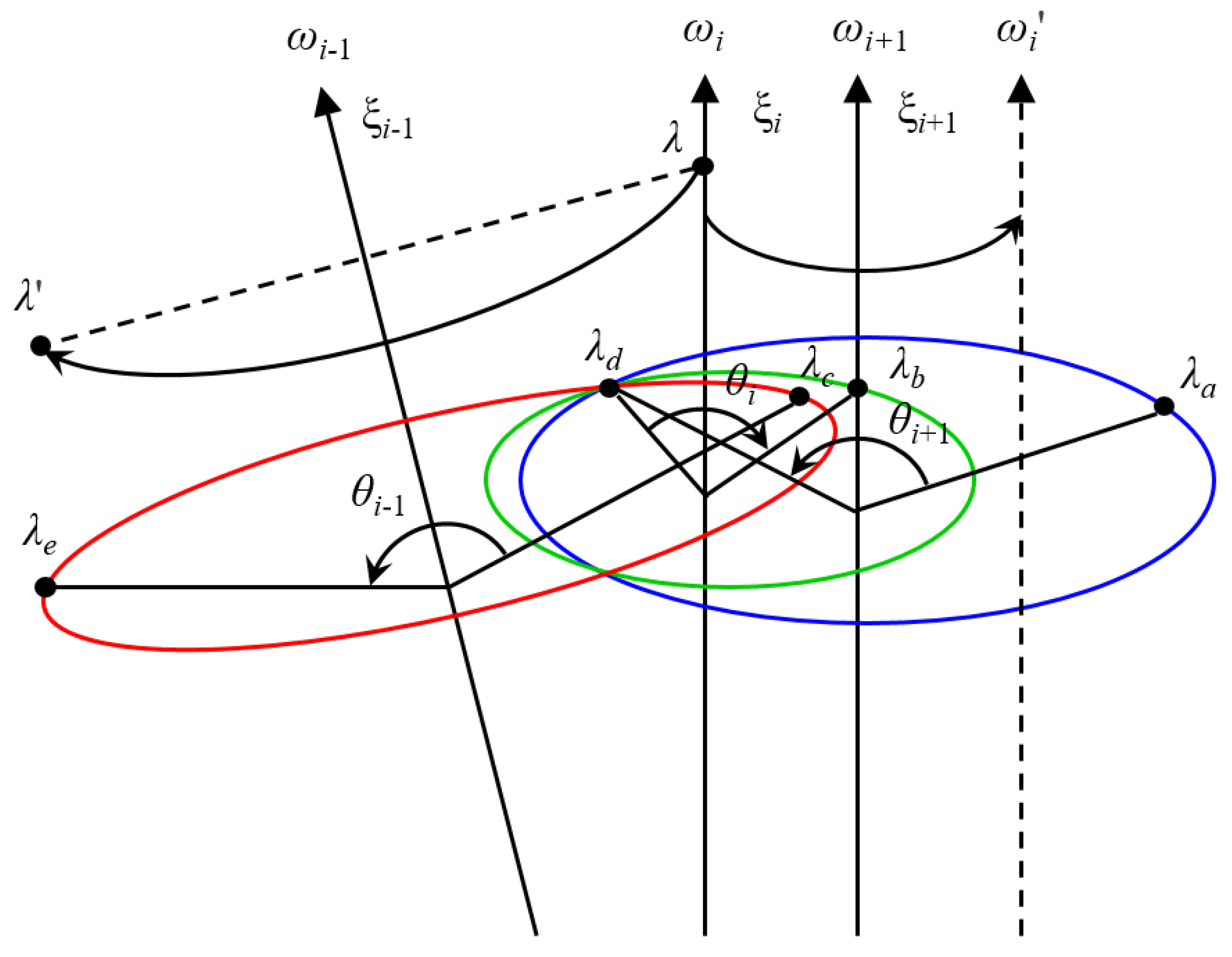
Figure 4 shows the geometric description of the rotation of vectors and points around a joint axis. According to Figure 4, it is evident that the directions of vectors ω i and ω i rotating around the axis of vector ω i+1 are the same. Furthermore, the projections of points λ and λ rotated around the axis of vector ω i−1 are the same.
As already mentioned, according to the structure of the seven-DOF space manipulator shown in Figure 2, it can be found that the third joint axis, the fourth joint axis, and the fifth joint axis of the manipulator are parallel. Based on screw theory, two conclusions can be obtained as follows.
Conclusion 1:
e ξ ^ 3 θ 3 e ξ ^ 4 θ 4 e ξ ^ 5 θ 5 · ω = ω .
As shown in Figure 4, when the motion of the manipulator is described by screw motion, if vector ω is parallel to the joint axis vector ω ii=3,4,5, the direction of ω always remains the same no matter how many degrees ω rotates around ω ii=3,4,5. This property can be expressed by Equation (11).
e ξ ^ 3 θ 3 · ω = ω e ξ ^ 4 θ 4 · ω = ω e ξ ^ 5 θ 5 · ω = ω
Bringing Equation (11) into Equation (8), Equation (12) can be obtained.
t n 11 t n 12 t n 13 t n 21 t n 22 t n 23 t n 31 t n 32 t n 33 · 1 0 0 = 1 0 0
Conclusion 2:
e ξ ^ 3 θ 3 e ξ ^ 4 θ 4 e ξ ^ 5 θ 5 · [ 0 , 0 , 0 , 1 ] T = [ 0 , , , 1 ] T
As shown in Figure 4, when the motion of the manipulator is described by screw motion, for any point λ in space, the first component of the λ coordinate always remains the same no matter how many degrees the point λ rotates around ω ii=3,4,5. This property can be expressed in Equation (14).
e ξ ^ 3 θ 3 · [ 0 , 0 , 0 , 1 ] T = [ 0 , , , 1 ] T e ξ ^ 4 θ 4 · [ 0 , 0 , 0 , 1 ] T = [ 0 , , , 1 ] T e ξ ^ 5 θ 5 · [ 0 , 0 , 0 , 1 ] T = [ 0 , , , 1 ] T
Bringing Equation (14) into Equation (8), Equation (15) can be obtained.
t n 14 = 0
In order to facilitate the representation of the formulas, the following abbreviations and symbols are defined for use in the derivation that follows:
s i = s i n ( θ i ) , s ij = s i n ( θ i + θ j ) , s ijk = s i n ( θ i + θ j + θ k ) c i = c o s ( θ i ) , c ij = c o s ( θ i + θ j ) , c ijk = c o s ( θ i + θ j + θ k )
s i c i = s i n ( θ i ) c o s ( θ i ) , c i s i = c o s ( θ i ) s i n ( θ i ) s i s i = s i n ( θ i ) s i n ( θ i ) , c i c i = c o s ( θ i ) c o s ( θ i )
Simplifying Equation (12), Equation (16) can be obtained.
c 1 c 2 s 1 c 2 s 2 = n x c 6 c 7 + a x s 6 o x c 6 s 7 n y c 6 c 7 + a y s 6 o y c 6 s 7 n z c 6 c 7 + a z s 6 o z c 6 s 7
For Equation (9), it is important to note that:
n x 2 + n y 2 + n z 2 = 1 , n x · o x + n y · o y + n z · o z = 0 o x 2 + o y 2 + o z 2 = 1 , n x · a x + n y · a y + n z · a z = 0 a x 2 + a y 2 + a z 2 = 1 , o x · a x + o y · a y + o z · a z = 0
Combining Equations (16) and (17), Equation (15) can be transformed into Equation (18).
A s i n θ 6 + B c o s θ 6 + C = 0
A = l 1 + l 2 + a x p x + a y p y + a z p z B = b 1 c o s θ 7 b 2 s i n θ 7 C = m 4 m 3 m 5 b 1 = m 3 m 4 + m 5 + n x p x + n y p y + n z p z b 2 = m 2 + m 6 + o x p x + o y p y + o z p z
Let:
s i n θ 6 = 2 t 1 + t 2 c o s θ 6 = 1 t 2 1 + t 2
Based on Equation (19), Equation (18) can be transformed into Equation (20).
( C B ) t 2 + 2 A t + ( C + B ) = 0
When A 2 + B 2 C 2 0 and C B , two sets of solutions for t are obtained [37], which is shown in Equation (21).
t = A ± A 2 + B 2 C 2 ( C B )
According to Equation (21), the expression of θ 6 can be obtained, which is shown as follows:
θ 6 = a t a n 2 ( 2 t , 1 t 2 )
According to Equation (16), the value of the sine function for θ 2 can be obtained as shown in Equation (23).
s 2 = o z c 6 s 7 n z c 6 c 7 a z s 6
Two sets of solutions for θ 2 are obtained based on Equation (23), which is shown as Equation (24).
θ 2 = a r c s i n ( o z c 6 s 7 n z c 6 c 7 a z s 6 ) θ 2 = π a r c s i n ( o z c 6 s 7 n z c 6 c 7 a z s 6 )
Since the solution of θ 2 has been found, the sine and cosine function value of θ 1 can be obtained based on Equations (16) and (24), as shown in Equation (25).
s 1 = n y c 6 c 7 + a y s 6 o y c 6 s 7 c 2 c 1 = n x c 6 c 7 + a x s 6 o x c 6 s 7 c 2
According to Equation (25), the solution of θ 1 can be obtained as shown in Equation (26).
θ 1 = a t a n 2 ( s i n θ 1 , c o s θ 1 )
Equation (27) can be obtained from Equation (8).
T n = 1 0 0 0 0 c 345 s 345 P 0 s 345 c 345 Q 0 0 0 1
P = m 2 ( 1 c 345 ) l 1 s 3 l 2 s 34 + ( l 1 + l 2 ) s 345 Q = l 1 c 3 + l 2 c 34 ( l 1 + l 2 ) c 345 m 2 s 345
According to Equations (8) and (27), Equations (28) and (29) can be obtained.
s i n ( θ 3 + θ 4 + θ 5 ) = t n 32 c o s ( θ 3 + θ 4 + θ 5 ) = t n 22
l 1 s 3 + l 2 s 34 = m 2 m 2 t n 22 + ( l 1 + l 2 ) t n 32 t n 24 l 1 c 3 + l 2 c 34 = t n 34 + ( l 1 + l 2 ) t n 22 + m 2 t n 32
Taking the sum of squares on both sides of the two equations above and below Equation (29) and then adding them together gives Equation (30).
K 1 2 + K 2 2 = l 1 2 + l 2 2 + 2 l 1 l 2 c o s θ 4
K 1 = m 2 m 2 t n 22 + ( l 1 + l 2 ) t n 32 t n 24 K 2 = t n 34 + ( l 1 + l 2 ) t n 22 + m 2 t n 32
Two sets of solutions for θ 4 (Figure 5) can be obtained according to Equation (30) [37], as shown in Equation (31).
θ 4 = ± a r c c o s K 1 2 + K 2 2 l 1 2 l 2 2 2 l 1 l 2
Bringing the value of θ 4 into Equation (29), the values of sine and cosine function for θ 3 can be obtained, as shown in Equation (32).
s i n θ 3 = K 1 l 1 + K 1 l 2 c o s θ 4 K 2 l 2 s i n θ 4 K 1 2 + K 2 2 c o s θ 3 = K 2 l 1 + K 2 l 2 c o s θ 4 + K 1 l 2 s i n θ 4 K 1 2 + K 2 2
According to Equation (32), two sets of solutions for θ 3 can be obtained, as shown in Equation (33).
θ 3 = a t a n 2 ( s i n θ 3 , c o s θ 3 )
Bringing the values of θ 3 and θ 4 into Equation (27), the solution of θ 5 can be obtained, which is shown as Equation (34).
θ 5 = a t a n 2 ( t n 32 , t n 22 ) θ 3 θ 4

5. Determination of Optimal Parametric Joint Angle

5.1. Determination of Optimal Solution Branch Based on Self-Motion Manifolds

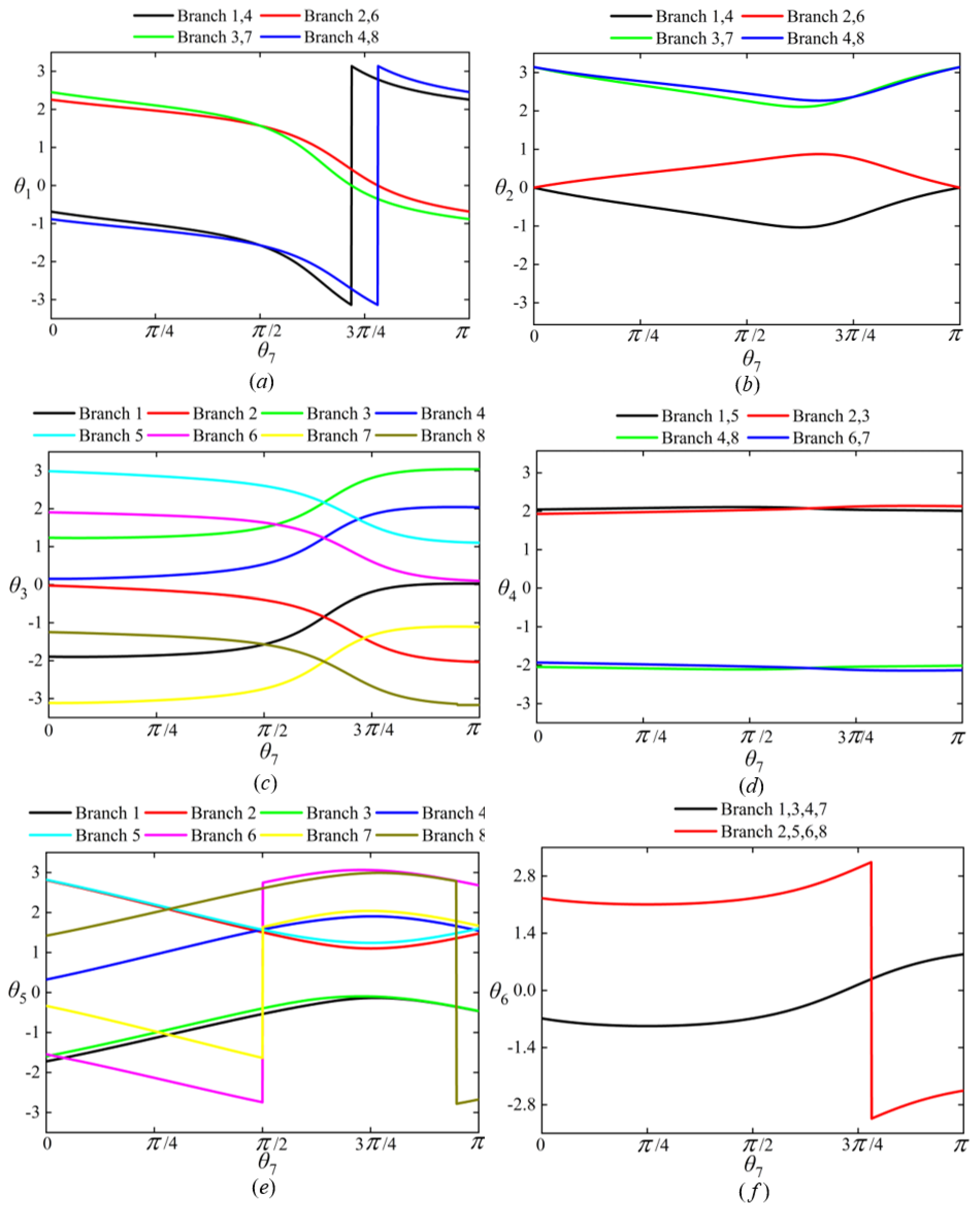
Self-motion manifolds contain all inverse kinematic solutions for a given pose. It is feasible to determine the optimal solution branch by comparing different self-motion manifold branches [38,39,40,41], which avoids the problem of multiple solutions. Given the target position [5 m, 5 m, 5 m] and rotation angles around the x-axis, y-axis, and z-axis [90°, 0°, 0°], the self-motion manifolds for the parametric joint angle θ 7 and non-parametric joint angles θ 1 to θ 6 can be obtained based on closed-form expressions for the non-parametric joint angles (Section 4).
Figure 6 shows the projections of self-motion manifolds on planes θ 7 θ i ( 1 i 6 ). These manifolds are curves in the space of ( θ 1 , θ 2 , θ 7 ) and are represented projected in planes in Figure 6. In Figure Figure 6a,e,f, the sudden changes in angles θ 1 , θ 5 , and θ 6 are due to angular wrapping. This is an unavoidable computational defect: when computing any angle using inverse trigonometric functions, if the angle goes above + π or below π , it reappears from the opposite place (i.e., π or + π , respectively). This is an apparent discontinuity and not a true discontinuity.
According to Figure 6, it is obvious that there are eight branches of self-motion manifolds. The optimal branch of self-motion manifolds can be determined by comparative analysis of all self-motion manifold branches. For a more specific comparative analysis of self-motion manifold branches, the flexibility index of minimum condition number is proposed, which can be expressed as follows:
k 1 = σ m i n σ m a x
where k 1 represents the flexibility index of minimum condition number, which takes value in range of [0, 1]. σ min and σ max represent the minimum and maximum singular values of the Jacobian, respectively. k 1 reflects the manipulability of the manipulator [42]. Different k 1 values will have the following effects on the manipulator:
  • When k 1 = 1, it indicates that the Jacobian is perfectly conditioned, meaning the manipulator is in its optimal configuration for performing tasks. This implies that the manipulator can exert equal force or velocity in all directions, making it highly dexterous.
  • When k 1 is closer to 1, it suggests that the manipulator is less sensitive to control errors or perturbations, which means it can operate more accurately.
  • When k 1 deviates significantly from 1, the manipulator may be in a configuration where it is more prone to errors, as certain directions in the task space might be difficult to control accurately.
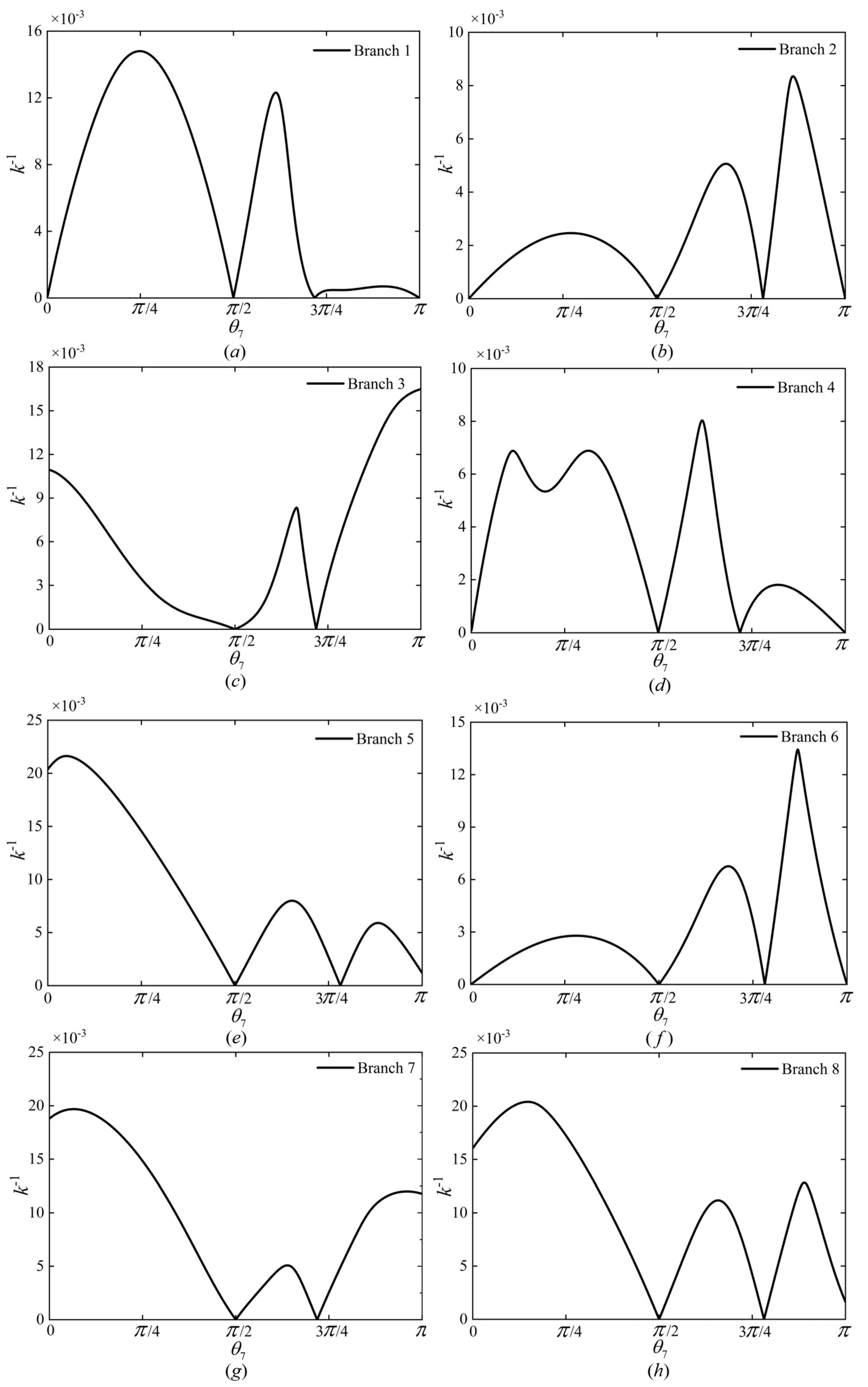
Figure 7 shows the variation in k−1 with respect to θ 7 in each self-motion manifold branch. In Figure 7a–h, when the parameter joint angle θ 7 is π /2 and near 3 π /4, the indicator value of k−1 becomes zero. This indicates that at this point, the maximum singularity value is infinite, i.e., singularity occurs. Therefore, θ 7 should avoid taking values π /2 and near 3 π /4.
According to Figure 7, the optimal k−1 of the optimal branch can be determined by comparing the maximum value of k−1 in different branches. The maximum value of k−1 is used to evaluate the optimal performance of each branch. After that, the optimal parametric joint angle θ 7 can be determined based on the optimal k−1 of the optimal branch. Non-parametric joint angles θ 1 to θ 6 can also be determined based on the expressions described in Section 4. For the trajectory tracking task, [ θ 1 , θ 2 , …, θ 7 ] is used as the joint configuration θ for the first path point, and the optimal branch will be used as solution branch for the computation of objective function in a subsequent trajectory tracking task.

5.2. Determination of Optimal Parametric Joint Angle Based on a Trajectory Tracking Task

Although self-motion manifolds provide all possible solutions, choosing the best of them does not always meet the needs of practical applications. It is still crucial to solve the optimization problem in order to obtain the best solution, especially when considering practical applications such as energy consumption, system stability, or path planning. By selecting a solution branch based on self-motion manifolds for subsequent optimization, the need to analyze multiple solutions is avoided, thereby enhancing solution efficiency.
For the trajectory tracking task, a hybrid (analytical and numerical) method is proposed to optimize θ 7. Compared to conventional analytical and numerical methods, the proposed method is more advantageous in dealing with complex manipulator structures and avoiding singularities. It uses a local traversal search strategy to find the optimal solution. The joint configurations are obtained based on forward kinematics, thereby avoiding the computation of the inverse Jacobian and the effects of singularities.
Conventional optimization methods take each joint angle as input, use the range of joint angles as constraint conditions, and finally output the minimum value of the objective function [43]. The optimization process can be described by Equation (36).
m i n f ( θ 1 , . . . , θ i , . . . , θ n ) , s u b j e c t t o θ i min θ i θ i max
where f represents the objective function, θ i ( 1 i n ) represents the i-th joint angle, n represents the total number of DOF. θ i min and θ i max represent the minimum and maximum values of the i-th joint angle, respectively. Unlike numerical iteration methods [16,44], the proposed method does not require the computation of the inverse Jacobian. Furthermore, the complexity of the objective function is reduced by reducing the number of dimensions to be optimized, which is more advantageous in terms of computational speed. The simulation results in Section 6.2 demonstrate this. The optimization process can be described by Equation (37).
m i n f ( θ 7 ) , s u b j e c t t o θ 7 min θ 7 θ 7 max
where θ 7 represents the parametric joint angle. θ 7 min and θ 7 max represent the minimum and maximum values of θ 7 , respectively. By comparing Equations (36) and (37), the multi-objective optimization problem with constraints can be transformed into a one-dimensional optimization problem.
After specifying the inverse kinematic problem of robotic manipulator, it is necessary to construct a suitable objective function. The most frequently used function of conventional optimization methods is shown in Equation (38).
f = T real T expect 2
where Treal and Texpect represent the actual and desired pose of the end effector, respectively. · 2 represents the Euclidean norm. For the trajectory tracking task, this paper proposed a new objective function, which is shown as Equation (39).
f = α T real T expect 2 + β i = 1 n θ i θ i 1 2
where θ i represents the corresponding joint configuration at the i-th path point. n represents the number of path points. Both α and β are random numbers between [0, 1] and α + β = 1.
The second term of the objective function is designed based on the minimum joint change criterion, which ensures that the transformation of adjacent joint angles is minimized, thereby ensuring the continuity and smoothness of the overall joint angle changes during trajectory tracking. Compared to conventional objective function, the proposed objective function considers both the accuracy of the target pose and the continuity of joint angles.
The purpose of the optimization is not only to ensure that the end effector reaches the specified pose but also to ensure a smooth transition between consecutive joint configurations for the trajectory tracking task, which cannot be achieved by simply substituting θ 7 into the expressions derived in Section 4. This smoothness is important for practical applications where abrupt changes in joint angles can lead to mechanical stress or inefficient movement.
For space robots, optimization is useful for avoiding singular configurations and ensuring the controllability and stability of the robot. This is crucial for preventing operational errors and potential damage to the spacecraft. Additionally, optimization reduces mechanical stress by ensuring smooth transitions between joint configurations, thereby extending the operational lifespan of the space robot.
For the robot–spacecraft system, optimization enhances the reliability and stability of the system. Smooth movements minimize interference with the spacecraft trajectory, reduce mechanical stress, and decrease energy consumption, thereby improving overall system efficiency and increasing the success rate of the mission.
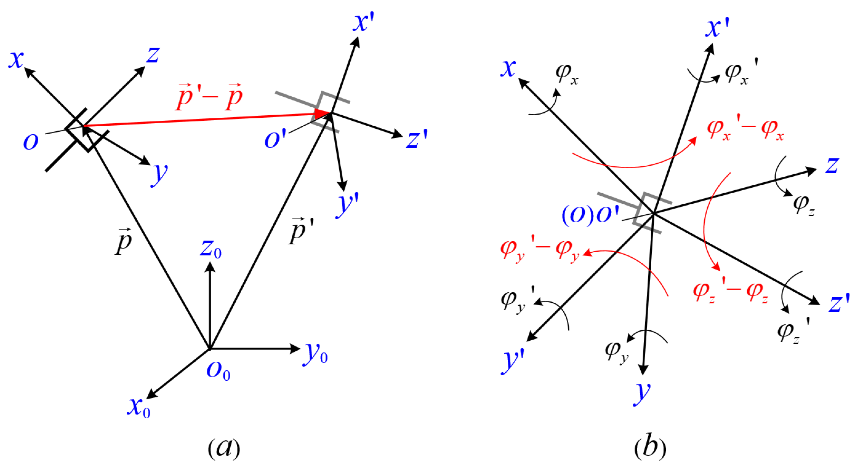
Figure 8 shows a schematic of the pose error for the manipulator. When the pose matrix of the end effector is known, the pose error refers to the norm between the actual pose matrix and the desired pose matrix. The desired pose matrix is the known pose matrix, while the actual pose matrix is obtained using the proposed algorithm. The pose error includes both the position error Δ p and the orientation errors (Euler angular errors) Δ ϕ x, Δ ϕ y, and Δ ϕ z are used for rotation around the x-axis, y-axis, and z-axis, respectively.
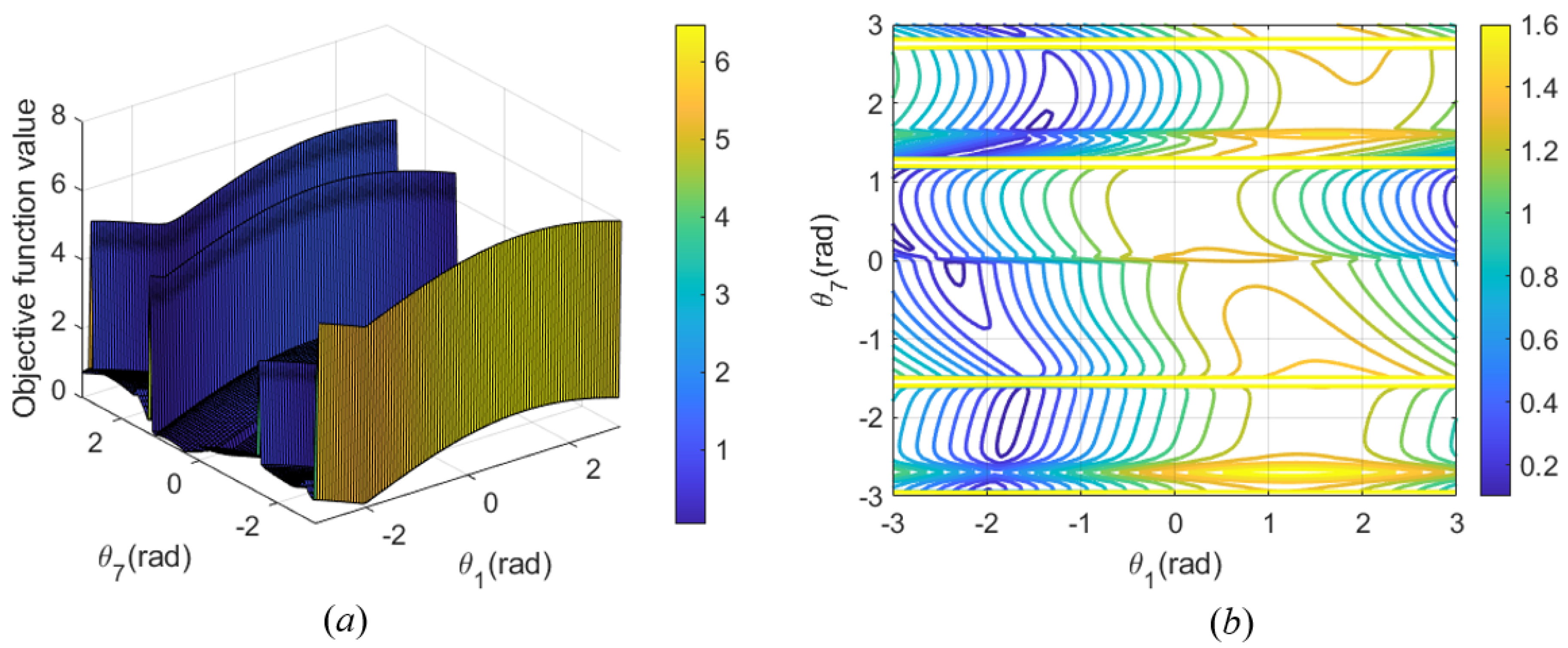
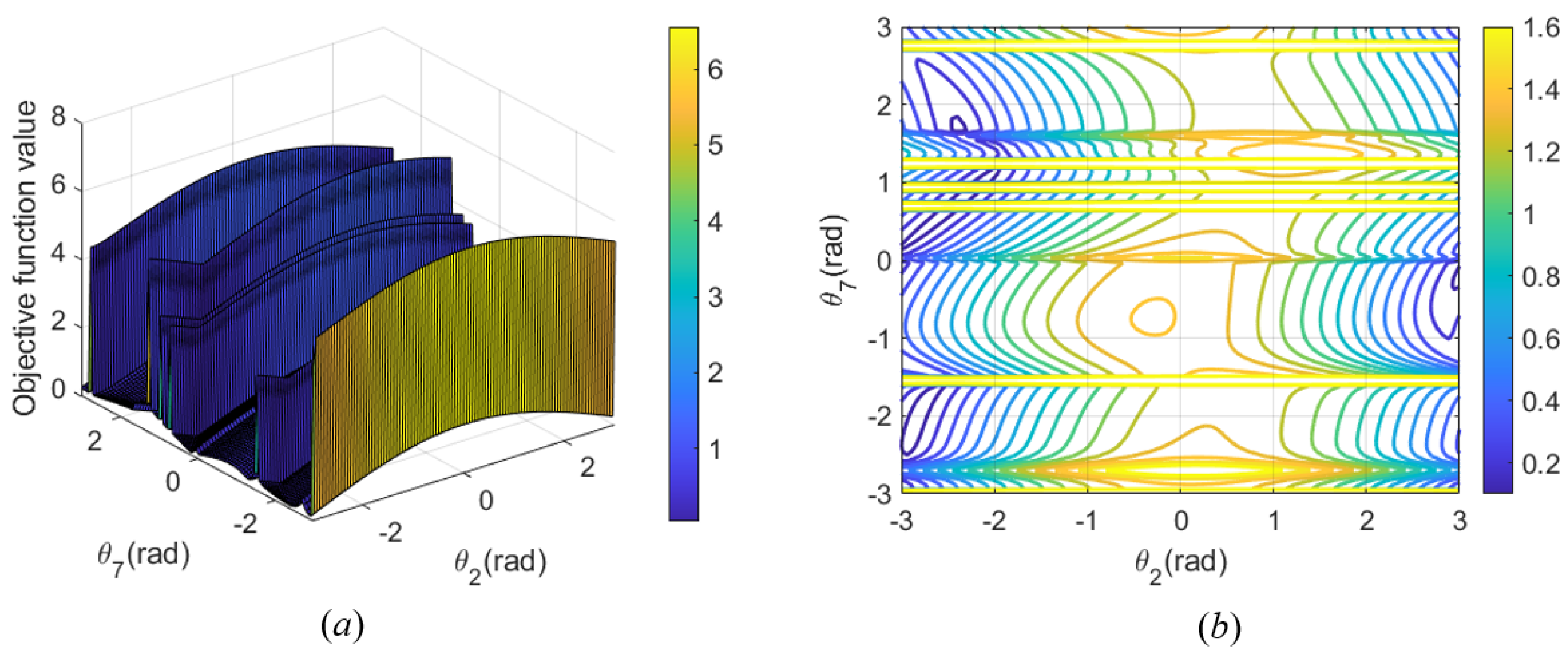
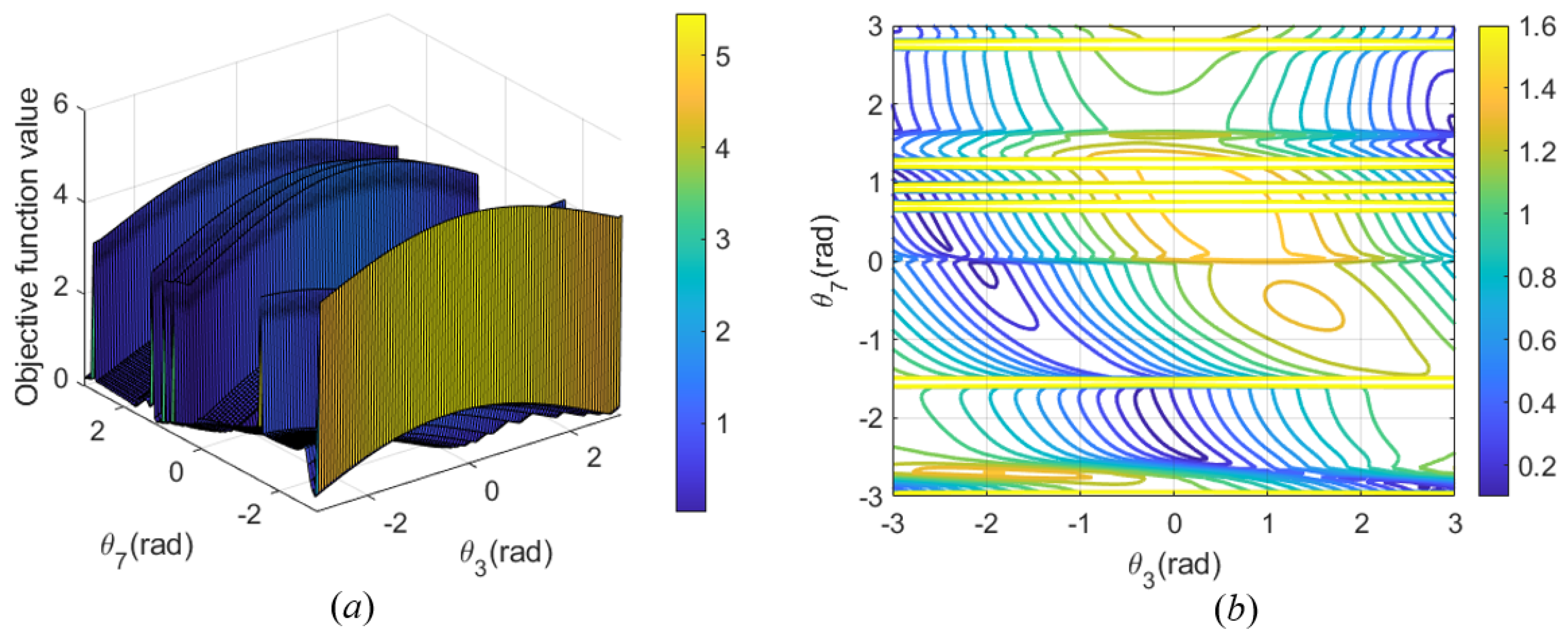
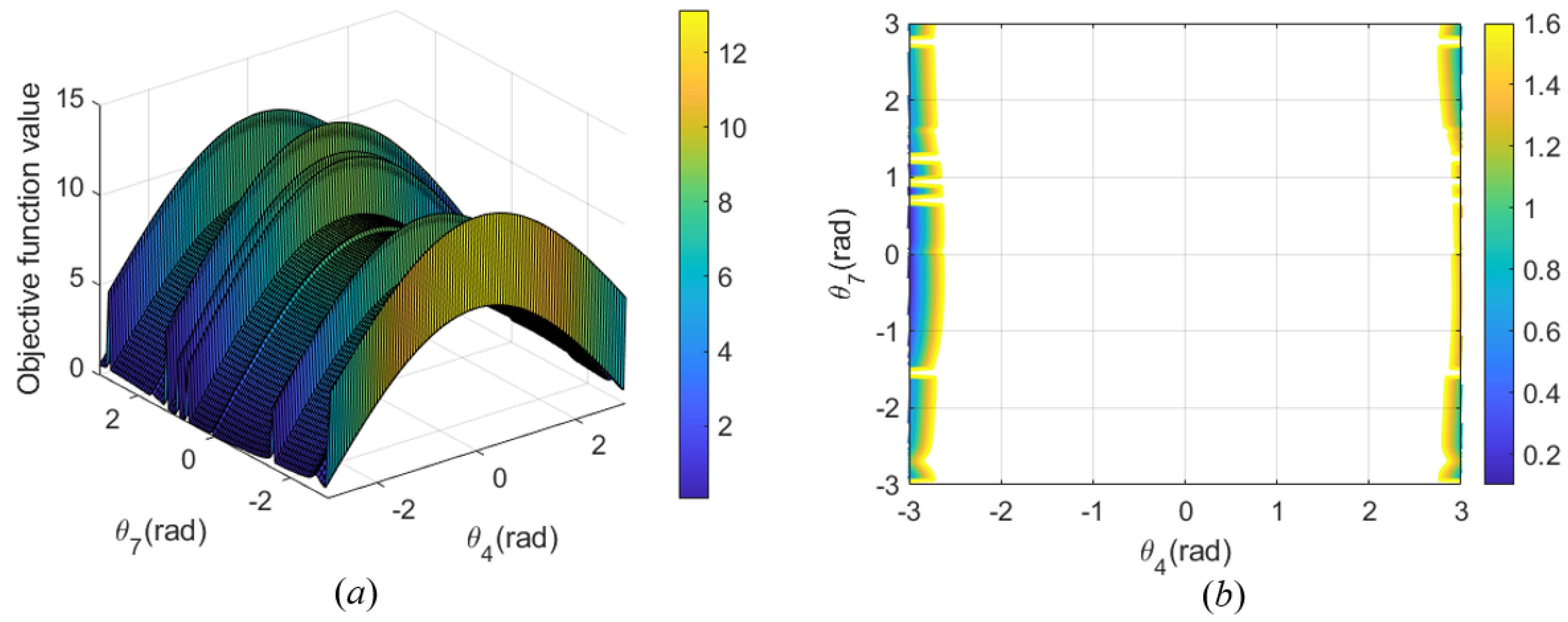
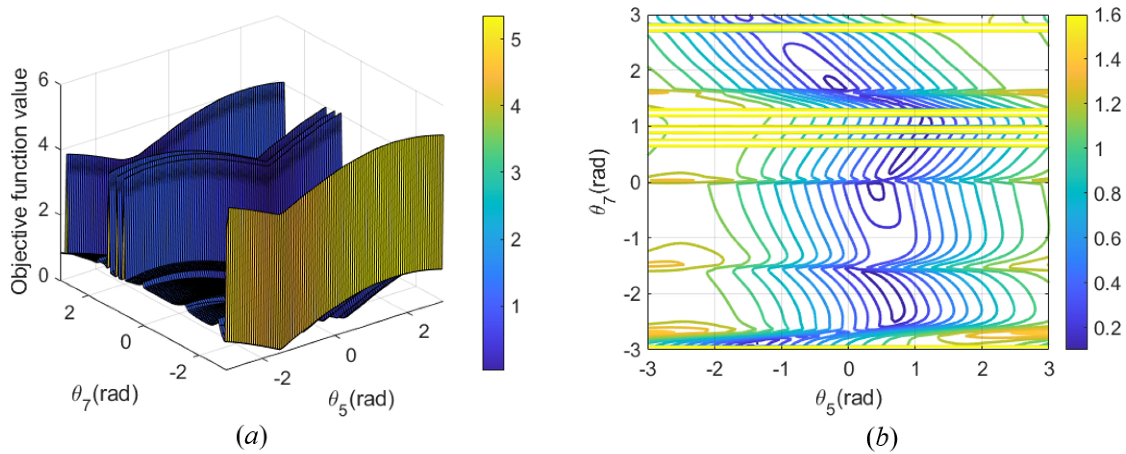
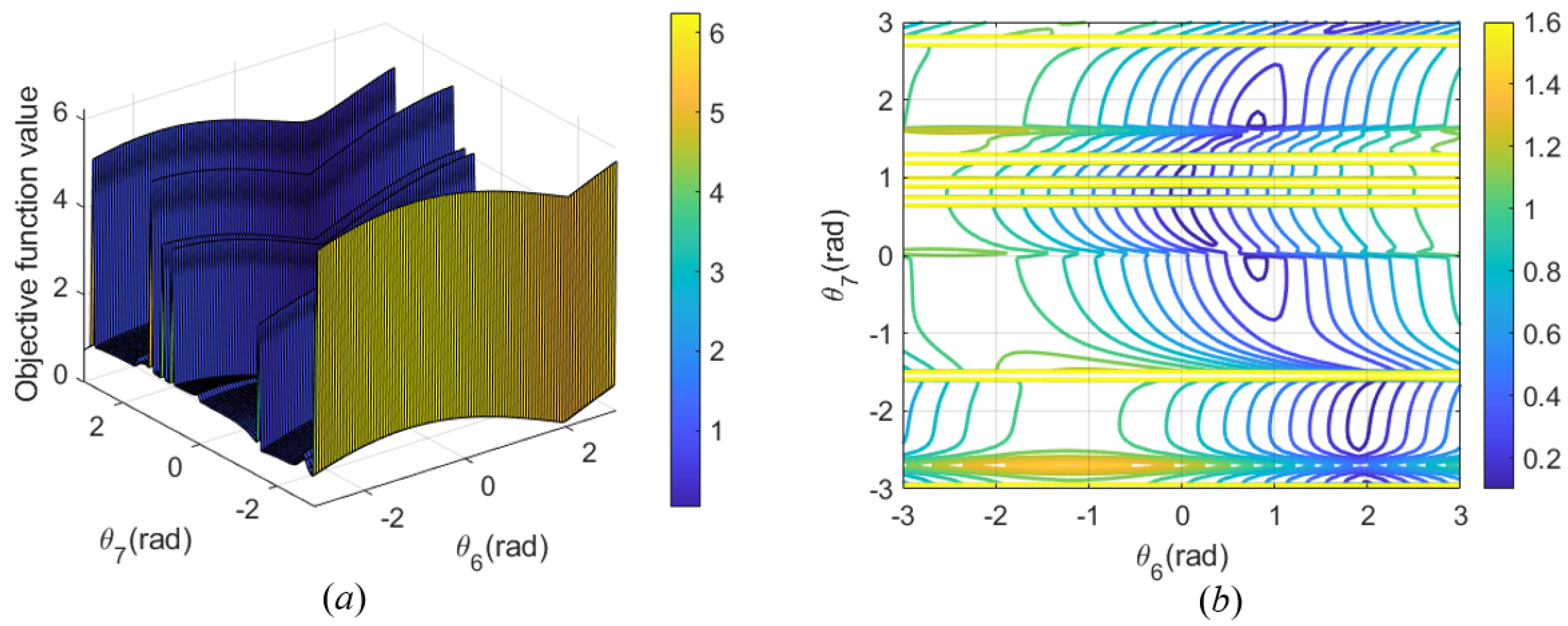
Given the target position [0.5 m, 0.5 m, 0.5 m] and rotation angles (Euler angles) for rotation around the x-axis, y-axis, and z-axis [90°, 0°, 0°], the objective functions about θ 7 and θ 1 to θ 6 are shown in Figure 9, Figure 10, Figure 11, Figure 12, Figure 13 and Figure 14.
Figure 9a, Figure 10a, Figure 11a, Figure 12a, Figure 13a and Figure 14a show three-dimensional surface plots of the objective function values, with the horizontal and vertical axes representing the values of parameters θ i (i = 1, ⋯, 6) and θ 7 , respectively, and the vertical axis representing the values of the objective function under the corresponding parameter combinations.
Figure 9b, Figure 10b, Figure 11b, Figure 12b, Figure 13b and Figure 14b are contour plots representing curves where the objective function takes the same value for different combinations of θ i (i = 1, ⋯, 6) and θ 7 . Different colors correspond to different values of the objective function, and the trend of the objective function can be observed from the color gradient. The denser the contour lines, the more drastic the change in the objective function. The smoother parts of the graph indicate that the objective function changes less in these areas.
In Figure 9a, Figure 10a, Figure 11a, Figure 12a, Figure 13a and Figure 14a, the extrema of the function are identified by the highest points (maxima) and the lowest points (minima) on the surface. In Figure 9b, Figure 10b, Figure 11b, Figure 12b, Figure 13b and Figure 14b, the yellow regions indicate the areas with higher function values (maxima), and the blue regions indicate lower function values (minima). These extremes reflect the impact of the interdependence between the joint angle pairs on the behavior of the objective function.
Although Figure 9, Figure 10, Figure 11, Figure 12, Figure 13 and Figure 14 suggest some independence between the angles, they are actually partial visualizations meant to illustrate the behavior of the objective function with respect to the angle pairs. The interdependence among all angles remains valid, and this does not contradict the findings in Section 4, which focus solely on specific aspects of the parameter space.
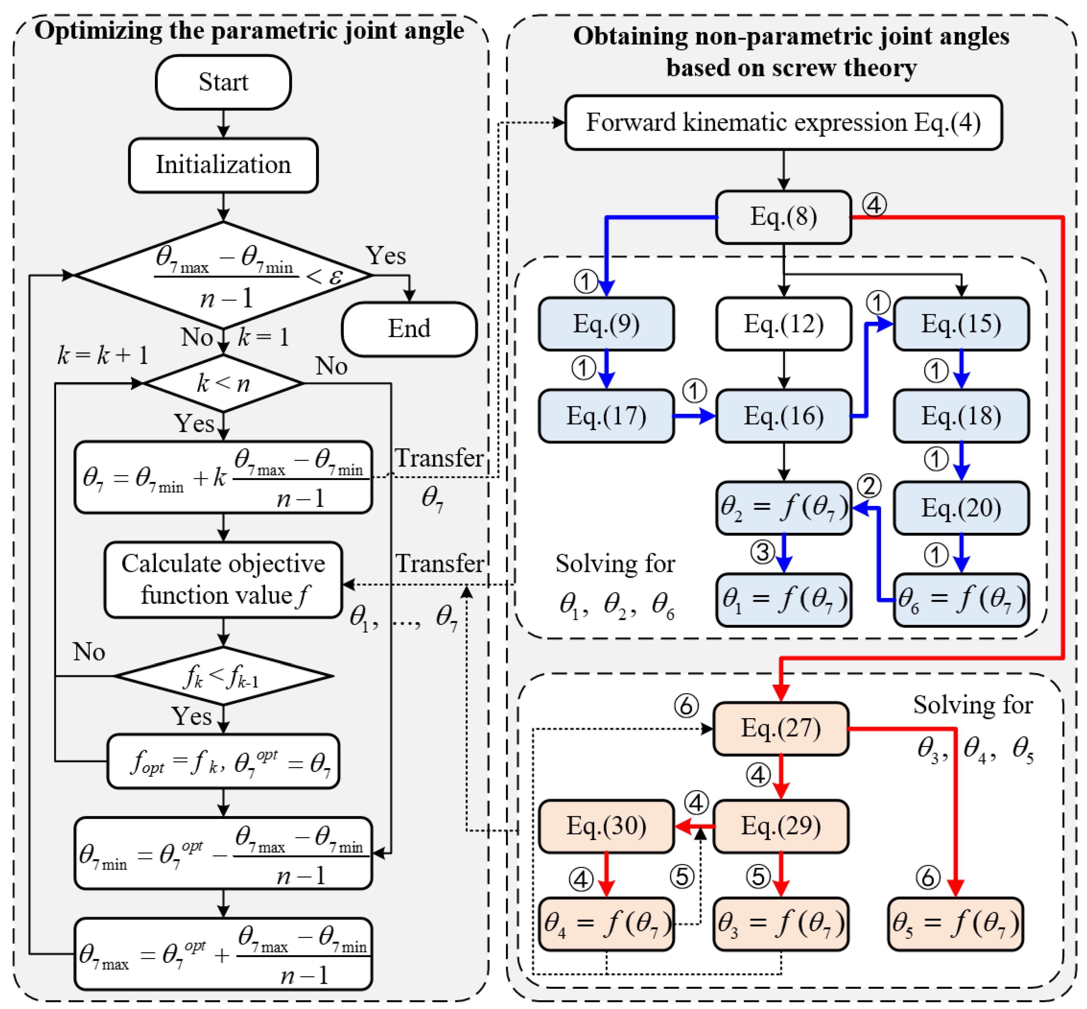
Figure 15 shows the flowchart for the optimization of θ 7 . The core idea is to divide the range of θ 7 into n − 1 parts at each level of the loop, select the optimal one from the n divisions based on the objective function Equation (39), and then narrow down the range of the optimal θ 7 . This cyclic searching process is repeated until the range of the optimal θ 7 satisfies the error criteria.

6. Simulation and Discussion

6.1. Preparation for Simulation

In this section, the proposed algorithm is evaluated through various simulations, and the results are discussed. First, a simulation for the inverse kinematics of discrete points was conducted. Second, simulations for the inverse kinematics of two continuous trajectories were performed. Finally, the simulation results are discussed and analyzed in Section 6.4. The parameter settings of the proposed algorithm are shown in Table 4.
To facilitate solving the inverse kinematics, the position of the base for the manipulator is set to [0, 0, 0] (m). The initial pose matrix of the end effector is shown in Equation (40).
T 0 = 1 0 0 m 3 m 4 + m 5 0 1 0 m 2 + m 6 0 0 1 l 1 + l 2 0 0 0 1
where T0 represents the initial pose matrix of the end effector. l1, l2, m2, m3, m4, m5, and m6 represent the link parameters of the manipulator.
In the simulations of discrete points and continuous trajectories, the orientation of the points changes. The process of computing the orientation matrix consists of (1) computing and normalizing the orientation vectors; (2) interpolating to generate smooth orientation changes; and (3) computing the rotation matrix.
When the coordinates of the i-th path point are known, the orientation vector and its normalized result for the i-th path point can be obtained, as shown in Equation (41) and Equation (42), respectively.
d i = ( x i + 1 x i , y i + 1 y i , z i + 1 z i ) i = 1 , 2 , . . . , n 1 ( x n x n 1 , y n y n 1 , z n z n 1 ) i = n
d ^ i = d i d i
In Equations (41) and (42), di represents the direction vector of the i-th path point. x i , y i , and z i represent the x-coordinate, y-coordinate, and z-coordinate of the i-th path point, respectively. n represents the number of path points. d ^ i represents the unit direction vector of the i-th path point. · represents the norm.
Subsequently, d ^ i is smoothed and normalized using the spline interpolation method to obtain the new orientation vector d ^ i . The expression for the rotation matrix of the i-th path point is presented in Equation (43).
R i = r ^ i u ^ i d ^ i , i = 1 , 2 , , n
r ^ i = u × d i u × d i u ^ i = d i × r ^ i d i × r ^ i
where R i represents the rotation matrix of the i-th path point. r ^ i , u ^ i , and d ^ i all represent the unit direction vectors of the i-th path point. u represents the positive direction vector and u = [0,0,1].
To evaluate the performance of the algorithm, the proposed algorithm was tested using two hundred sample points. The parameters of the proposed algorithm are listed in Table 4. The simulation was conducted on an Intel(R) Core(TM) i9-14900HX CPU with 16GB RAM, using MATLAB 2023.

6.2. Simulation of Discrete Points

This section aims to illustrate the accuracy of the proposed algorithm in solving inverse kinematics for discrete points and its advantages over other algorithms.
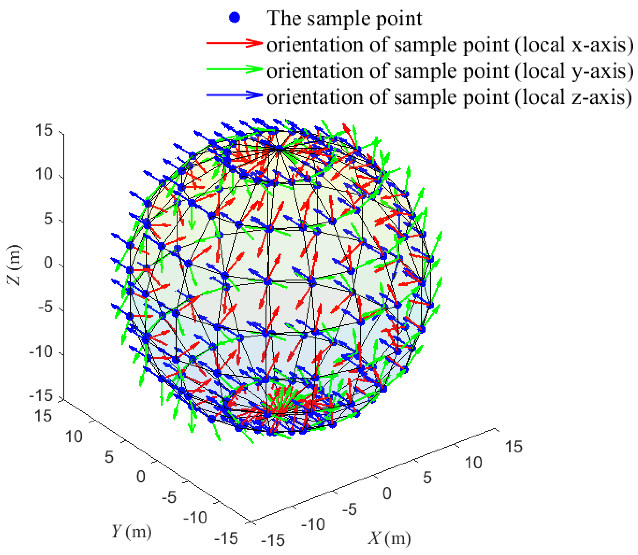
Two hundred points (the blue points in Figure 16) were generated on the surface of the sphere, with center coordinates [0, 0, 0] m and a radius of 15 m. The sampling points on the sphere are defined by the latitude angle ϕ ( ϕ [ 0 , Π ] rad) and the longitude angle Γ ( Γ [ 0 , 2 Π ] rad). The expression for the position of the sampling points is shown in Equation (44).
x ( i ) = 15 s i n ( Φ i ) c o s ( Γ j ) y ( i ) = 15 s i n ( Φ i ) s i n ( Γ j ) z ( i ) = 15 c o s ( Φ i )
Φ i = Π i N lat 1 i = 0 , 1 , . . . , N lat 1 Γ j = 2 Π j N lon 1 j = 0 , 1 , . . . , N lon 1
where x(i), y(i), and z(i) represent the x-coordinate, y-coordinate, and z-coordinate of the i-th sampling point, respectively. ϕ i and Γ j represent the latitude and longitude angles of the i-th and j-th discrete points, respectively. Nlat and Nlon represent the number of latitude and longitude angles, respectively.
To present the simulation results and demonstrate the accuracy of the algorithm, the position error (Figure 17a) and orientation error (Figure 17b) are shown in Equations (45) and (46).
P o s i t i o n e r r o r = p p 2
O r i e n t a t i o n e r r o r = ( ϕ x ϕ x ) 2 + ( ϕ y ϕ y ) 2 + ( ϕ z ϕ z ) 2
p = T real ( 1 : 3 , 4 ) ϕ x = a t a n 2 ( T real ( 3 , 2 ) , T real ( 3 , 3 ) ) ϕ y = a s i n ( T real ( 3 , 1 ) ) ϕ z = a t a n 2 ( T real ( 2 , 1 ) , T real ( 1 , 1 ) ) p = T expect ( 1 : 3 , 4 ) ϕ x = a t a n 2 ( T expect ( 3 , 2 ) , T expect ( 3 , 3 ) ) ϕ y = a s i n ( T expect ( 3 , 1 ) ) ϕ z = a t a n 2 ( T expect ( 2 , 1 ) , T expect ( 1 , 1 ) )
In Equations (45) and (46), · 2 represents the Euclidean norm. p and p represent the actual and desired positions of the end effector, respectively. ϕ x’, ϕ y’, and ϕ z’ represent the actual Euler angles of the end effector for rotation around the x-axis, y-axis, and z-axis, respectively, while ϕ x, ϕ y, and ϕ z represent the desired Euler angles for these rotations.
Figure 17a,b show the schematics of the position error and orientation error of the end effector, respectively. The position error represents the Euclidean norm of the difference between the desired position vector p and the actual position vector p . The orientation error represents the Euclidean distance between the desired Euler angles ( ϕ x, ϕ y, ϕ z) and the actual Euler angles ( ϕ x’, ϕ y’, ϕ z’) for rotation around the x-axis, y-axis, and z-axis, respectively.
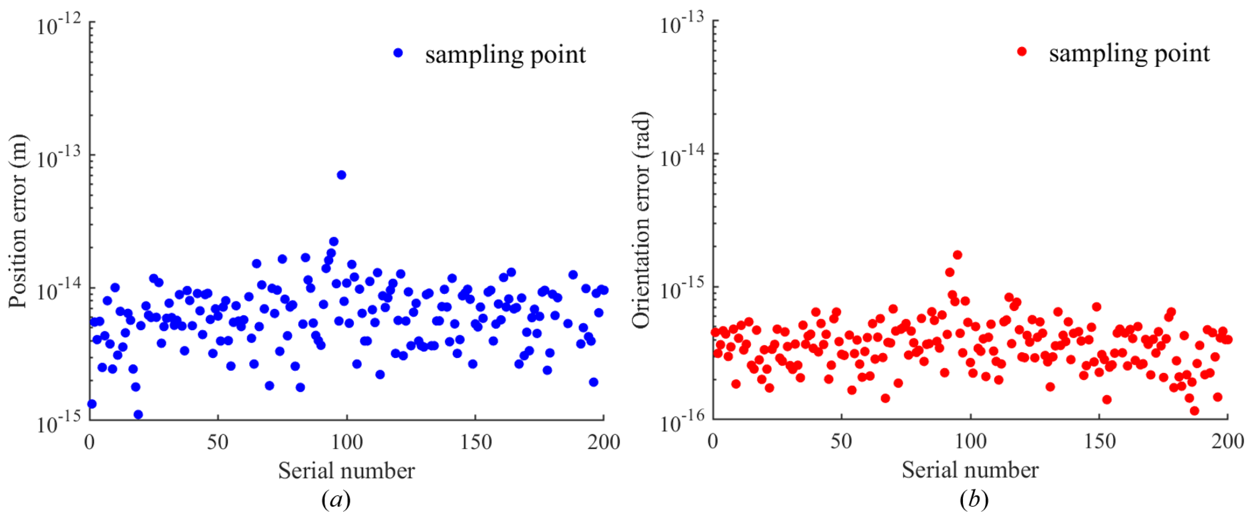
Figure 18a,b show the position and orientation errors of the proposed method, respectively. The position error represents the sum of the errors along the x-axis, y-axis, and z-axis, and the corresponding expression is shown in Equation (45). The orientation error represents the sum of the Euler angular errors for rotation around the x-axis, y-axis, and z-axis, and the corresponding expression is shown in Equation (46). According to Figure 18, the position error of the proposed algorithm stabilizes at 10−15 to 10−14 m, and the orientation error stabilizes at 10−16 to 10−15 rad. These results demonstrate that the proposed algorithm can stably search for high-precision solutions to the inverse kinematics for discrete points with different orientations.
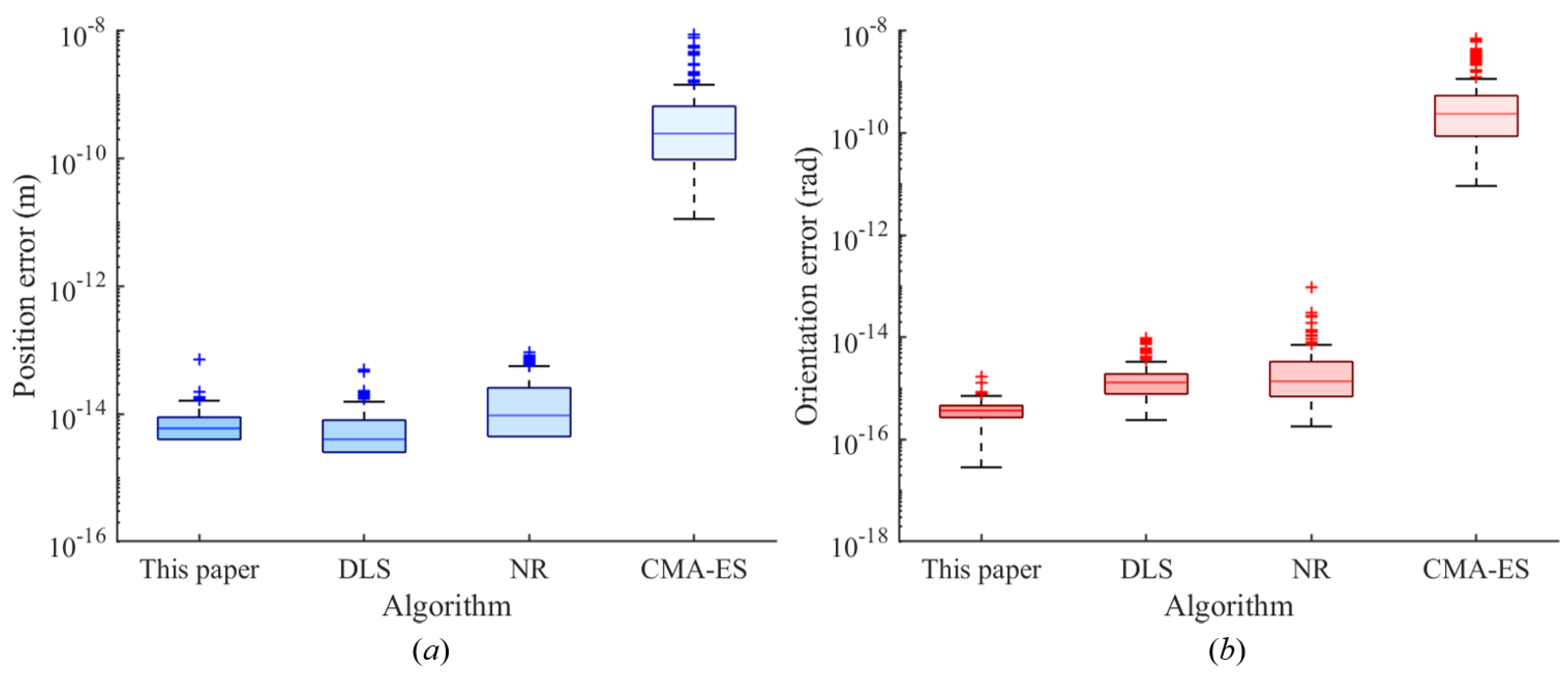
Figure 19a,b show the position and orientation errors of different algorithms, respectively. The definitions of position and orientation errors in Figure 19 are consistent with those in Figure 18. When comparing algorithms, the Damped Least Squares (DLS) algorithm [16] and the Newton–Raphson (NR) algorithm [44] are the most representative numerical iteration algorithms. The Covariance Matrix Adaptation Evolution Strategy (CMA-ES) algorithm [45] is the most commonly used numerical optimization algorithm. To ensure a fair comparison, the number of iterations n for all algorithms is set to 1000, and the loop termination condition for all algorithms is set to epsilon = 10−10. The results are represented using box plots.
According to Figure 19a, the proposed method and DLS algorithms exhibit smaller data distributions, lower resultant values, and fewer outliers in position error compared to the NR and CMA-ES algorithms. Figure 19b shows that the proposed method has smaller data distributions, lower resultant values, and fewer outliers in orientation error compared to the DLS, NR, and CMA-ES algorithms.
Table 5 shows the comparative computational time results for four algorithms across five tests. According to Table 5, the average computation time of the proposed algorithm for 200 sampling points across five tests is 0.4152 s. This is less than the computation time of the DLS algorithm (0.9496 s) and the NR algorithm (2.8067 s). While the proposed algorithm does not differ significantly from CMA-ES in terms of computation time, it offers higher positional and directional accuracy.
Table 6 shows the statistical results of 200 data sets in Figure 19 with respect to the success rate of the solution. Out of the 200 data sets, the algorithm is considered successful at the position error level when the position error is less than 10 9 m. Similarly, it is considered successful at the orientation error level when the orientation error is less than 10 9 rad. The results in Table 6 indicate that the proposed method has a higher solution success rate compared to other methods.

6.3. Simulation of Continuous Trajectories

Continuous trajectory simulation, compared to discrete point simulation, needs to ensure not only the accuracy of the inverse kinematics solution for a single point but also the smoothness of joint angles between neighboring path points.
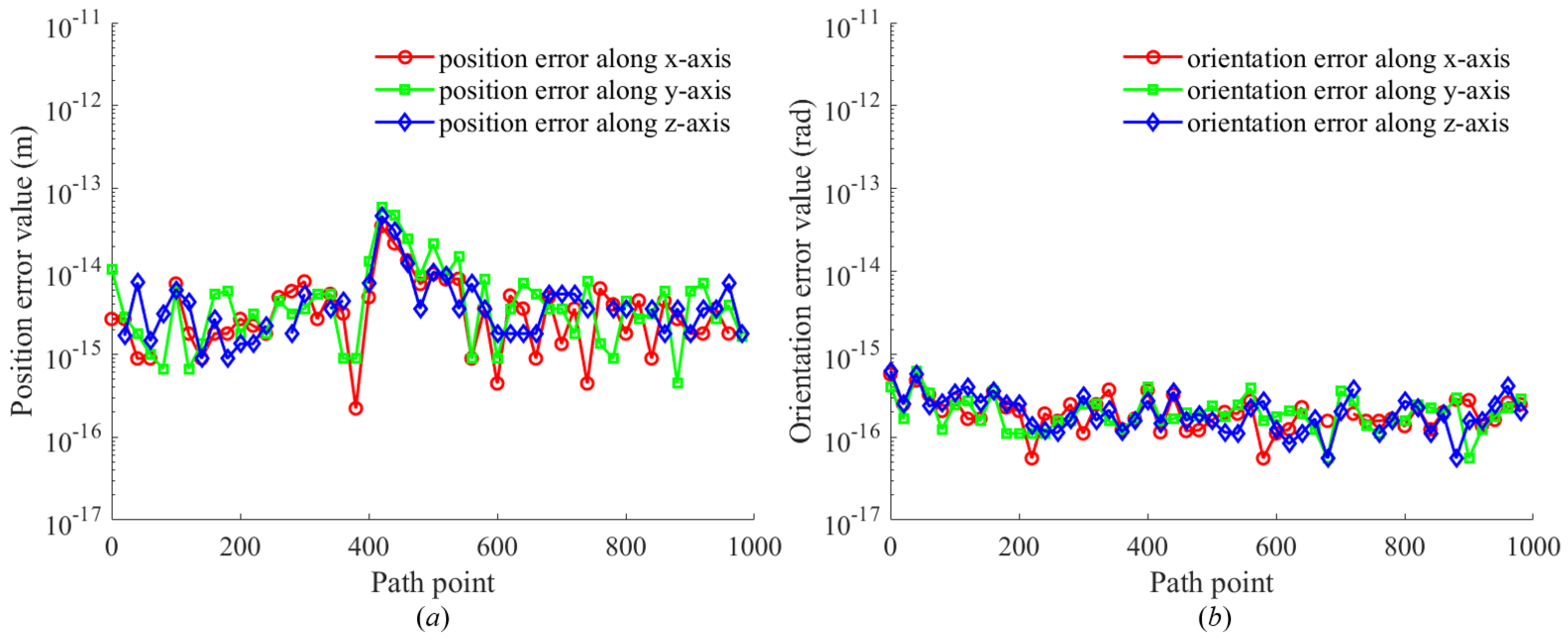
Two continuous trajectories are defined in space, and 1000 sample points are taken on the trajectories. Task 1 is a hyperbolic paraboloid from [0, 1, 0] m to [2, cosh(2), 2] m. Task 2 is a cylindrical spiral with a circle center at [0.0, 0.0] m, a radius of 5 m, and a height of 15 m. The specific definitions of the two trajectories are shown in Equation (47) and Equation (48), respectively.
x ( i ) = 2 i / 1000 y ( i ) = c o s h ( 2 i / 1000 ) i = 1 , . . . , 1000 z ( i ) = 2 i / 1000
x ( j ) = 5 c o s ( π j / 1000 ) y ( j ) = 5 s i n ( π j / 1000 ) j = 1 , . . . , 1000 z ( j ) = 15 j / 1000
The reason for choosing these trajectories is that they are spatial curves, and the orientation of different path points changes when the posture matrix is obtained using interpolation. The data obtained are more valuable when solving the inverse kinematics of path points with changing orientations.
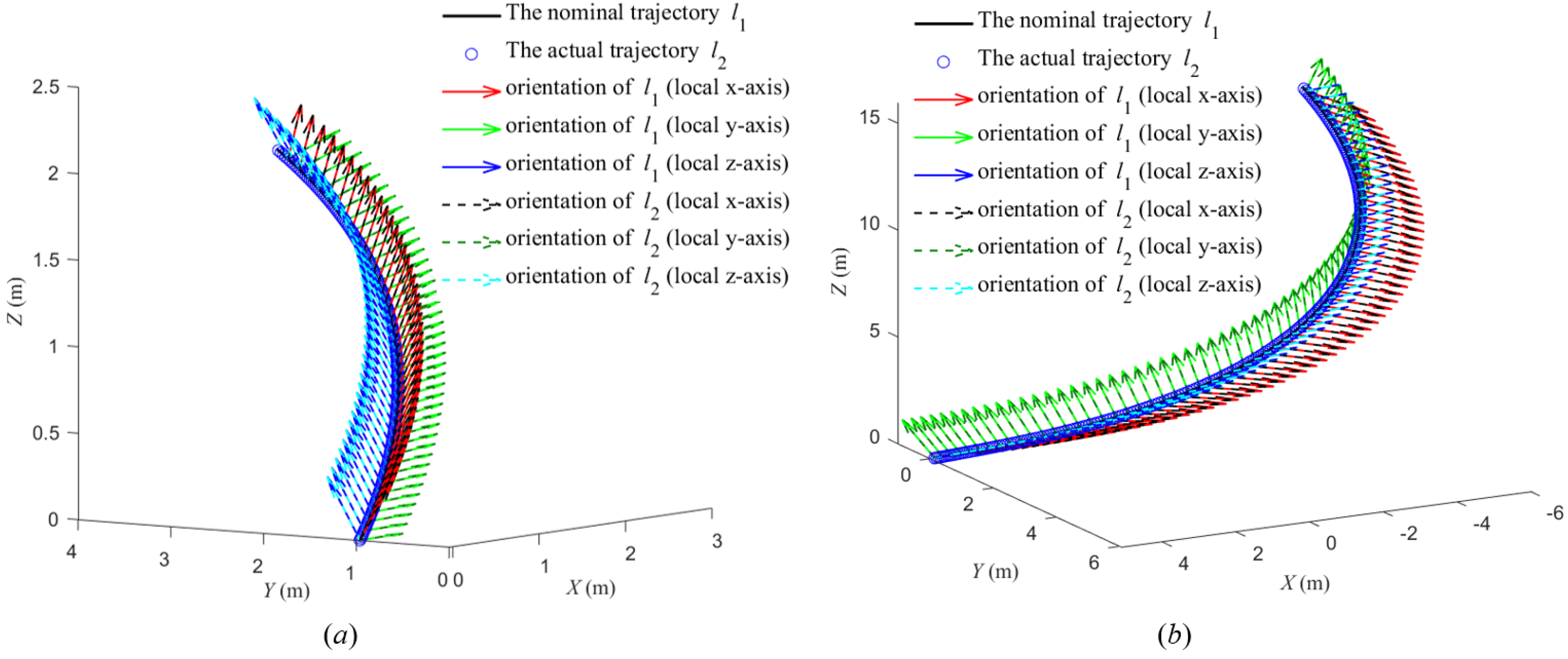
Figure 20 shows nominal trajectories 1 and 2 and their corresponding actual trajectories. The inverse kinematics corresponding to the sampling points for the two tasks are obtained based on the proposed method.
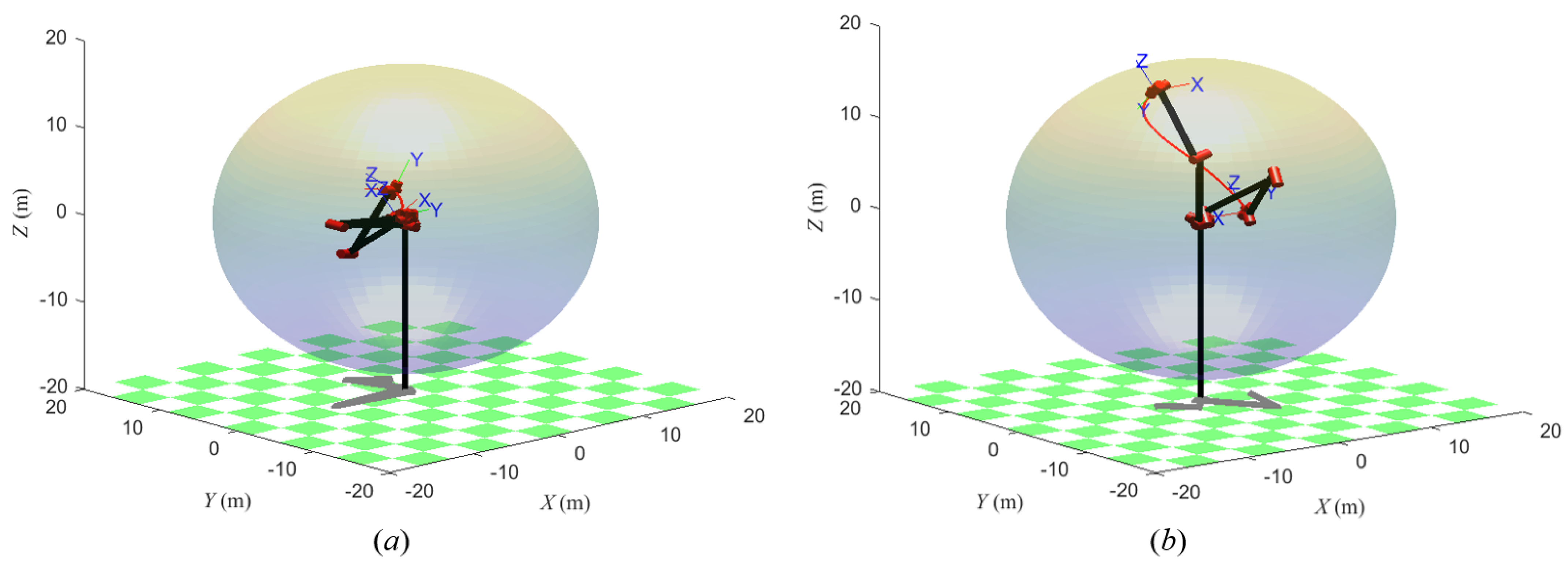
Figure 21 shows the positions of trajectory 1 and trajectory 2 in the workspace of the manipulator. The results in Figure 21 illustrate that the two trajectories are feasible, as both trajectories are inside the workspace, and the manipulator can reach the start and end points of the trajectories.
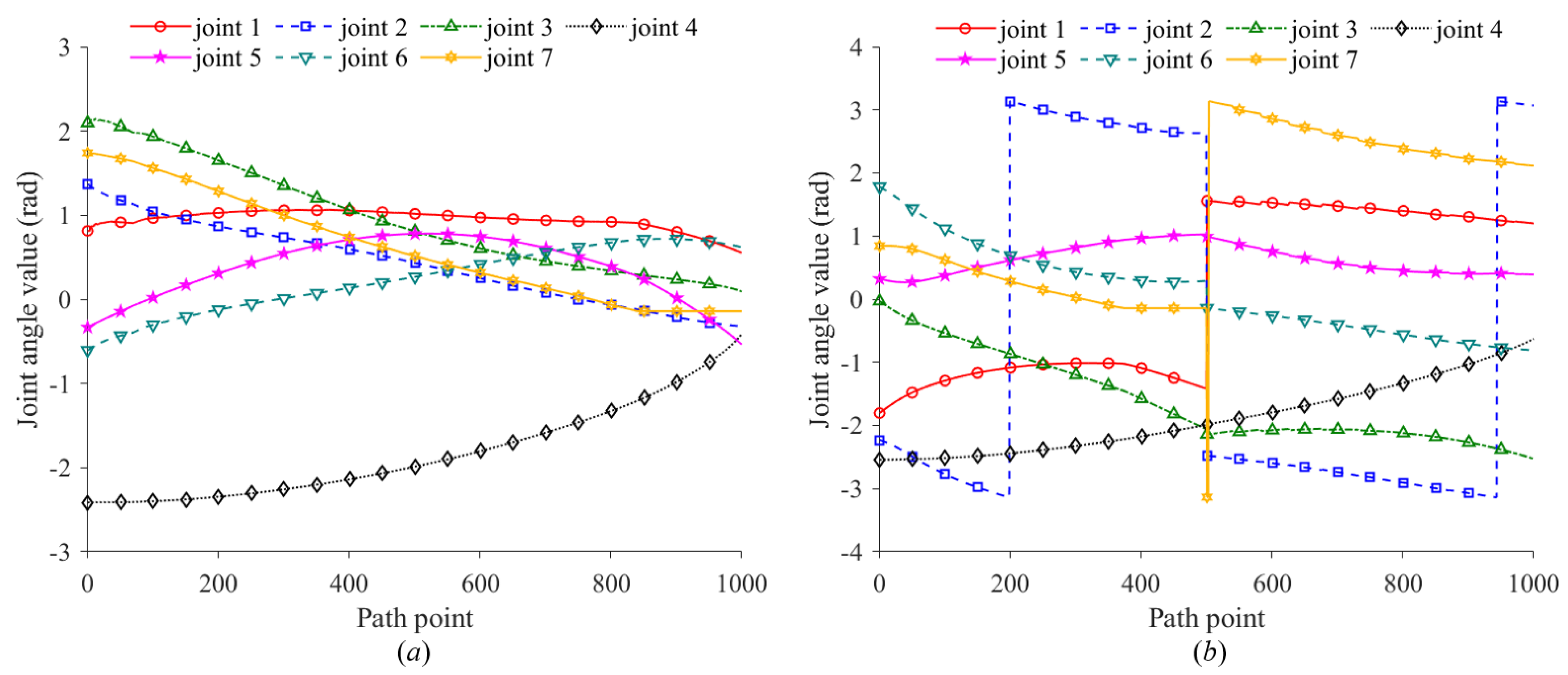
Figure 22 shows the variation in the seven joint angles with the path points in task 1. Figure 22a represents the variation in the seven joint angles when the joint configuration θ for the first path point is obtained based on self-motion manifolds. By comparing the maximum value of k−1 in each branch, the seventh branch is chosen as the optimal branch, and the optimal parametric joint angle θ 7 is determined (3.1416 rad). Thus, the optimal joint configuration θ for the first path point is [ 1.5722, 2.3462, 1.6164, 3.0544, 1.5282, 0.0100, 3.1416] rad. Figure 22b represents the variation in the seven joint angles when the joint configuration θ for the first path point is given randomly ( [ 0.7404, 0.8023, 0.1547, 2.6053, 1.5248, 2.8700, 1.2784] rad).
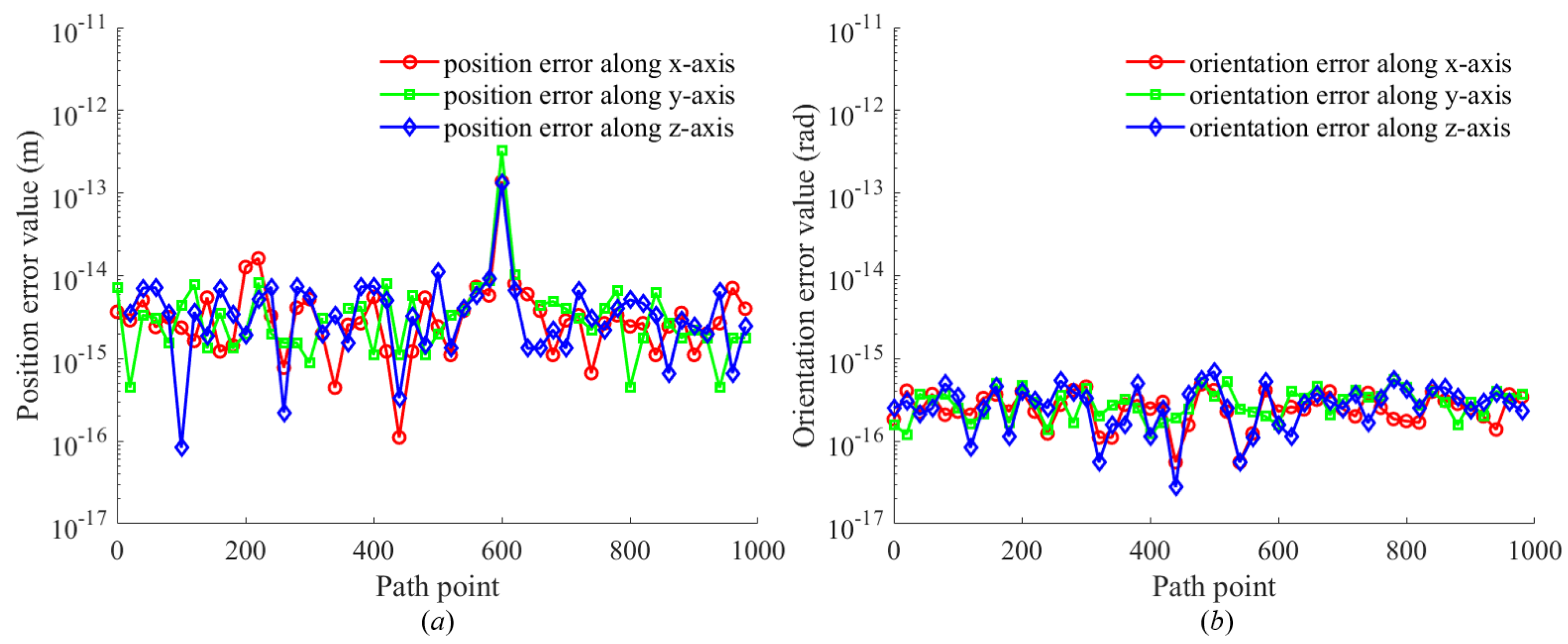
Figure 23 shows the position and orientation errors for 1000 sampling points in task 1. The position errors include errors along the x-axis, y-axis, and z-axis, while the orientation errors encompass the Euler angular errors for rotation around the x-axis, y-axis, and z-axis, respectively. According to Figure Figure 23, the position errors remain stable within the range of 10−15 to 10−14 m, and the orientation errors remain stable within the range of 10−16 to 10−15 rad.
Figure 24 shows the variation in the seven joint angles with the path points in task 2. Figure 24a represents the variation in the seven joint angles when the joint configuration θ for the first path point is obtained based on self-motion manifolds. By comparing the maximum value of k−1 in each branch, the fourth branch is chosen as the optimal branch, and the optimal parametric joint angle θ 7 is determined (1.7404 rad). Thus, the optimal joint configuration θ for the first path point is [ 0.8097, 1.3664, 2.0947, 2.4151, 0.3320, 0.6064, 1.7404] rad. Figure 24b represents the variation in the seven joint angles when the joint configuration θ for the first path point is given randomly ( [ 1.2020, 3.0683, 2.5278, 0.6255, 0.3989, 0.8086, 2.1201] rad).
Figure 25 shows the position and orientation errors for 1000 sampling points in task 2. The position errors include errors along the x-axis, y-axis, and z-axis, while the orientation errors encompass the Euler angular errors for rotation around the x-axis, y-axis, and z-axis, respectively. According to Figure 25, the position errors remain stable within the range of 10−15 to 10−14 m, and the orientation errors remain stable within the range of 10−16 to 10−15 rad.
The above simulation results demonstrate that the proposed method can further ensure the smoothness of joint angles while maintaining position and orientation accuracy in inverse kinematics. After analyzing the global performance of self-motion manifolds, the optimal branch of these manifolds is identified, aiding in the selection of the inverse kinematics solution branch, which effectively resolves the multiplicity resolution problem. The computational times of the proposed method for solving the inverse kinematics of two trajectories are 1.7789 s and 1.7757 s, respectively (Figure 22a and Figure 24a). When eight sets of solutions are compared simultaneously, the computational times are 13.6139 s and 13.3470 s, respectively (Figure 22b and Figure 24b).
The joint angles in Figure 22 and Figure 24 are calculated using the algorithm depicted in Figure 15. The joint configuration θ for the first path point in Figure 22a and Figure 24a is obtained based on the optimal parametric joint angle θ 7 . θ 7 is determined based on the optimal k−1 of the optimal branch, as described in Section 5.1. Compared to Figure 22b and Figure 24b, the joint angles in Figure 22a and Figure 24a are smoother and exhibit no localized fluctuations.

6.4. Discussion

The approach proposed in this study offers a significant advancement over traditional DH modeling by utilizing screw theory to address the kinematics of a space manipulator (Section 2). The primary advantage lies in the reduced complexity of the required coordinate systems, focusing solely on the base and tool coordinate systems, which simplifies the characterization process while maintaining accuracy.
The workspace analysis method introduced provides a novel way of determining the redundant joint by eliminating non-redundant ones and comparing subspace volumes (Section 3). This method not only identifies redundancy but also offers a computationally efficient strategy for managing it in complex manipulator systems, which is particularly valuable in systems with a high degree of freedom.
One of the most notable contributions is the application of screw theory to derive the inverse kinematic solutions (Section 4). The properties of screw theory, particularly the preservation of direction in parallel vectors and consistent projection in rotating points, provide a robust framework for solving the inverse kinematics of non-parametric joint angles. This approach has potential applications beyond the specific case studies discussed and could influence the design and control of other robotic systems with similar requirements.
Moreover, while the self-motion manifold is theoretically capable of directly identifying the optimal solution, it becomes computationally intensive when considering all possible solutions. In this study, it is primarily used to select the optimal solution branch and determine the joint configuration for the first path point (Section 5.1). By leveraging the minimum joint change criterion, this approach enhances computational efficiency and improves the smoothness and stability of joint movements, ensuring a high-quality solution while reducing unnecessary joint fluctuations. This strategy effectively balances the thoroughness of solution space exploration with the practical demands of real-time path planning.
Finally, the hybrid method combining analytical and numerical approaches offers a practical solution to the inverse kinematics problem (Section 5.2), particularly for space manipulators with adjacent parallel axes. The optimization strategy introduced for the parametric joint angle enhances the precision and robustness of the kinematic solutions, as demonstrated by the simulation results. This hybrid approach could be further explored in more complex or dynamically changing environments, opening avenues for real-time applications.
This study investigates the inverse kinematics of a seven-DOF space manipulator with a non-spherical wrist structure, leading to several significant contributions:
  • To tackle the challenge of joint decoupling in a seven-DOF manipulator with a non-spherical wrist, closed-form inverse kinematics expressions for joint angles are derived based on screw theory.
  • For the identification and optimization of the redundant parameter, a workspace analysis method is used to identify the redundant joint, and the redundant parameter is optimized based on a trajectory tracking task.
  • Simulation results show that, compared to the CMA-ES algorithm, the proposed method increases the solving success rate from 84.5% to 95.5% for position errors under 10 9 m, and from 85% to 99% for orientation errors under 10 9 rad. Additionally, it reduces computation time by 56% compared to the DLS algorithm, highlighting its efficiency in solving inverse kinematics.
Future research could explore the application of the proposed method to different types of manipulators, particularly in scenarios requiring high precision under dynamic conditions.
Author Contributions

Conceptualization, D.J.; methodology, G.Z.; software, J.Y.; validation, D.J., J.Y.; formal analysis, H.F.; investigation, G.Z.; resources, D.J.; data curation, H.F.; writing—original draft preparation, G.Z.; writing—review and editing, B.T.; visualization, H.F.; supervision, J.Y.; project administration, B.T.; funding acquisition, B.T. All authors have read and agreed to the published version of the manuscript.

Funding

This research was funded by grants of the National Natural Science Foundation of China (Grant Nos.52075530, 51575407, 51975324, 51505349, 61733011, 41906177); the Grants of Hubei Provincial Department of Education (D20191105); the Grants of National Defense PreResearch Foundation of Wuhan University of Science and Technology (GF201705) and Open Fund of the Key Laboratory for Metallurgical Equipment and Control of Ministry of Education in Wuhan University of Science and Technology (2018B07, 2019B13) and Open Fund of Hubei Key Laboratory of Hydroelectric Machinery Design & Maintenance in China Three Gorges University (2020KJX02, 2021IKJX13). This research was also supported by project of short-term overseas visiting for graduate students of Wuhan University of Science and Technology.

Institutional Review Board Statement

Not applicable.

Informed Consent Statement

Not applicable.

Data Availability Statement

Data generated during the current study are available from the corresponding author on reasonable request. The data are available, but restrictions apply to the availability of these data, which were used under license for the current study and are not publicly available.

Conflicts of Interest

The authors declare no conflicts of interest. The funders had no role in the design of the study; in the collection, analyses, or interpretation of data; in the writing of the manuscript; or in the decision to publish the results.

References

  1. Gao, Y.; Chien, S. Review on space robotics: Toward top-level science through space exploration. Sci. Robot. 2017, 2, eaan5074. [Google Scholar] [CrossRef] [PubMed]
  2. Flores-Abad, A.; Ma, O.; Pham, K.; Ulrich, S. A review of space robotics technologies for on-orbit servicing. Prog. Aerosp. Sci. 2014, 68, 1–26. [Google Scholar] [CrossRef]
  3. Li, K.; Tian, Q.; Shi, J.; Liu, D. Assembly dynamics of a large space modular satellite antenna. Mech. Mach. Theory 2019, 142, 103601. [Google Scholar] [CrossRef]
  4. Gao, Y. Contemporary Planetary Robotics: An Approach toward Autonomous Systems; John Wiley & Sons: Hoboken, NJ, USA, 2016. [Google Scholar]
  5. Baker, D.R.; Wampler, C.W. On the inverse kinematics of redundant manipulators. Int. J. Robot. Res. 1988, 7, 3–21. [Google Scholar] [CrossRef]
  6. Khatib, O. Real-time obstacle avoidance for manipulators and mobile robots. Int. J. Robot. Res. 1986, 5, 90–98. [Google Scholar] [CrossRef]
  7. Hauser, K.; Emmons, S. Global redundancy resolution via continuous pseudoinversion of the forward kinematic map. IEEE Trans. Autom. Sci. Eng. 2018, 15, 932–944. [Google Scholar] [CrossRef]
  8. Liu, Y.; Wang, D.; Sun, J.; Chang, L.; Ma, C.; Ge, Y.; Gao, L. Geometric approach for inverse kinematics analysis of 6-dof serial robot. In Proceedings of the 2015 IEEE International Conference on Information and Automation, Lijiang, China, 8–10 August 2015; pp. 852–855. [Google Scholar]
  9. Huang, L.; Jiang, R. A new method of inverse kinematics solution for industrial 7DOF robot. In Proceedings of the 32nd Chinese Control Conference, Xi’an, China, 26–28 July 2013; pp. 6063–6065. [Google Scholar]
  10. Wei, Y.; Jian, S.; He, S.; Wang, Z. General approach for inverse kinematics of nR robots. Mech. Mach. Theory 2014, 75, 97–106. [Google Scholar] [CrossRef]
  11. Kim, J.S.; Jeong, J.H.; Park, J.H. Inverse kinematics and geometric singularity analysis of a 3-SPS/S redundant motion mechanism using conformal geometric algebra. Mech. Mach. Theory 2015, 90, 23–36. [Google Scholar] [CrossRef]
  12. Colomé, A.; Torras, C. Closed-loop inverse kinematics for redundant robots: Comparative assessment and two enhancements. IEEE/ASME Trans. Mechatronics 2014, 20, 944–955. [Google Scholar] [CrossRef]
  13. Singh, G.K.; Claassens, J. An analytical solution for the inverse kinematics of a redundant 7DoF manipulator with link offsets. In Proceedings of the 2010 IEEE/RSJ International Conference on Intelligent Robots and Systems, Taipei, Taiwan, 18–22 October 2010; pp. 2976–2982. [Google Scholar]
  14. Tong, Y.; Liu, J.; Liu, Y.; Yuan, Y. Analytical inverse kinematic computation for 7-DOF redundant sliding manipulators. Mech. Mach. Theory 2021, 155, 104006. [Google Scholar] [CrossRef]
  15. Wampler, C.W. Manipulator inverse kinematic solutions based on vector formulations and damped least-squares methods. IEEE Trans. Syst. Man, Cybern. 1986, 16, 93–101. [Google Scholar] [CrossRef]
  16. Safeea, M.; Bearee, R.; Neto, P. A modified DLS scheme with controlled cyclic solution for inverse kinematics in redundant robots. IEEE Trans. Ind. Inform. 2021, 17, 8014–8023. [Google Scholar] [CrossRef]
  17. Gupta, K.; Kazerounian, K. Improved numerical solutions of inverse kinematics of robots. In Proceedings of the 1985 IEEE International Conference on Robotics and Automation, St. Louis, MO, USA, 25–28 March 1985; Volume 2, pp. 743–748. [Google Scholar]
  18. Chiaverini, S.; Egeland, O.; Kanestrom, R.K. Achieving user-defined accuracy with damped least-squares inverse kinematics. In Proceedings of the Fifth International Conference on Advanced Robotics’ Robots in Unstructured Environments, Pisa, Italy, 19–22 June 1991; pp. 672–677. [Google Scholar]
  19. Ananthanarayanan, H.; Ordóñez, R. Real-time inverse kinematics of redundant manipulator using a hybrid (analytical and numerical) method. In Proceedings of the 2013 16th International Conference on Advanced Robotics (ICAR), Montevideo, Uruguay, 25–29 November 2013; pp. 1–6. [Google Scholar]
  20. Kuhlemann, I.; Schweikard, A.; Jauer, P.; Ernst, F. Robust inverse kinematics by configuration control for redundant manipulators with seven DoF. In Proceedings of the 2016 2nd International Conference on Control, Automation and Robotics (ICCAR), Hong Kong, China, 28–30 April 2016; pp. 49–55. [Google Scholar]
  21. Lee, S.; Bejczy, A.K. Redundant arm kinematic control based on parameterization. In Proceedings of the IEEE International Conference on Robotics and Automation, Sacramento, CA, USA, 9–11 April 1991; pp. 458–459. [Google Scholar]
  22. Zaplana, I.; Basanez, L. A novel closed-form solution for the inverse kinematics of redundant manipulators through workspace analysis. Mech. Mach. Theory 2018, 121, 829–843. [Google Scholar] [CrossRef]
  23. Tondu, B. A closed-form inverse kinematic modelling of a 7R anthropomorphic upper limb based on a joint parametrization. In Proceedings of the 2006 6th IEEE-RAS International Conference on Humanoid Robots, Genova, Italy, 4–6 December 2006; pp. 390–397. [Google Scholar]
  24. Shimizu, M.; Kakuya, H.; Yoon, W.K.; Kitagaki, K.; Kosuge, K. Analytical inverse kinematic computation for 7-DOF redundant manipulators with joint limits and its application to redundancy resolution. IEEE Trans. Robot. 2008, 24, 1131–1142. [Google Scholar] [CrossRef]
  25. Dou, R.; Yu, S.; Li, W.; Chen, P.; Xia, P.; Zhai, F.; Yokoi, H.; Jiang, Y. Inverse kinematics for a 7-DOF humanoid robotic arm with joint limit and end pose coupling. Mech. Mach. Theory 2022, 169, 104637. [Google Scholar] [CrossRef]
  26. Burdick, J.W. On the inverse kinematics of redundant manipulators: Characterization of the self-motion manifolds. In Advanced Robotics: 1989: Proceedings of the 4th International Conference on Advanced Robotics Columbus; Springer: Berlin/Heidelberg, Germany, 1989; pp. 25–34. [Google Scholar]
  27. Vahrenkamp, N.; Asfour, T.; Metta, G.; Sandini, G.; Dillmann, R. Manipulability analysis. In Proceedings of the 2012 12th IEEE-Ras International Conference on Humanoid Robots (Humanoids 2012), Osaka, Japan, 29 November–1 December 2012; pp. 568–573. [Google Scholar]
  28. Ananthanarayanan, H.; Ordóñez, R. A fast converging optimal technique applied to path planning of hyper-redundant manipulators. Mech. Mach. Theory 2017, 118, 231–246. [Google Scholar] [CrossRef]
  29. Xiao, F.; Li, G.; Jiang, D.; Xie, Y.; Yun, J.; Liu, Y.; Huang, L.; Fang, Z. An effective and unified method to derive the inverse kinematics formulas of general six-DOF manipulator with simple geometry. Mech. Mach. Theory 2021, 159, 104265. [Google Scholar] [CrossRef]
  30. Zhang, X.; Li, G.; Xiao, F.; Jiang, D.; Tao, B.; Kong, J.; Jiang, G.; Liu, Y. An inverse kinematics framework of mobile manipulator based on unique domain constraint. Mech. Mach. Theory 2023, 183, 105273. [Google Scholar] [CrossRef]
  31. Meng, D.; Ouyang, X.; Tan, J.; Wang, X.; Liang, B. Kinematics modeling method of continuum space manipulator based on virtual discrete-jointed manipulator models. Acta Astronaut. 2023, 211, 257–267. [Google Scholar] [CrossRef]
  32. Rocha, C.R.; Tonetto, C.P.; Dias, A. A comparison between the Denavit–Hartenberg and the screw-based methods used in kinematic modeling of robot manipulators. Robot. -Comput.-Integr. Manuf. 2011, 27, 723–728. [Google Scholar] [CrossRef]
  33. Ceccarelli, M. Screw axis defined by Giulio Mozzi in 1763 and early studies on helicoidal motion. Mech. Mach. Theory 2000, 35, 761–770. [Google Scholar] [CrossRef]
  34. Sariyildiz, E.; Temeltas, H. A comparison study of three screw theory based kinematic solution methods for the industrial robot manipulators. In Proceedings of the 2011 IEEE International Conference on Mechatronics and Automation, Beijing, China, 7–10 August 2011; pp. 52–57. [Google Scholar]
  35. Xie, J.; Qiang, W.; Liang, B.; Li, C. Inverse kinematics problem for 6-DOF space manipulator based on the theory of screws. In Proceedings of the 2007 IEEE International Conference on Robotics and Biomimetics (ROBIO), Sanya, China, 15–18 December 2007; pp. 1659–1663. [Google Scholar]
  36. Lee, T.; Yang, D. On the evaluation of manipulator workspace. ASME J. Mech. Transm. Autom. Des. 1983, 105, 70–77. [Google Scholar] [CrossRef]
  37. Kreyszig, E. The application of trigonometric functions and algebraic solutions. In Advanced Engineering Mathematics, 10th ed.; John Wiley & Sons, Inc.: Hoboken, NJ, USA, 2011; pp. 145–168. [Google Scholar]
  38. Machado, J.A.T.; Lopes, A.M. A fractional perspective on the trajectory control of redundant and hyper-redundant robot manipulators. Appl. Math. Model. 2017, 46, 716–726. [Google Scholar] [CrossRef]
  39. Wu, T.; Zhao, J.; Zhang, Z.; Zhang, Q.; Zhou, Y. Regions identifying of serial redundant robot’s workspace constrained by performance. In Proceedings of the 2020 2nd International Conference on Artificial Intelligence, Robotics and Control, Cairo, Egypt, 12–14 December 2020; pp. 49–54. [Google Scholar]
  40. Xia, J.; Jiang, Z.; Zhang, H.; Zhu, R.; Tian, H. Dual fast marching tree algorithm for human-like motion planning of anthropomorphic arms with task constraints. IEEE/ASME Trans. Mechatronics 2020, 26, 2803–2813. [Google Scholar] [CrossRef]
  41. Lin, Y.; He, F.; Cui, X.; Wang, F.; Yu, H. A search strategy for motion planning of unmanned crawler crane. In Proceedings of the 2019 7th International Conference on Control, Mechatronics and Automation (ICCMA), Delft, The Netherlands, 6–8 November 2019; pp. 299–304. [Google Scholar]
  42. Yoshikawa, T. Manipulability of robotic mechanisms. Int. J. Robot. Res. 1985, 4, 3–9. [Google Scholar] [CrossRef]
  43. El-Sherbiny, A.; Elhosseini, M.A.; Haikal, A.Y. A new ABC variant for solving inverse kinematics problem in 5 DOF robot arm. Appl. Soft Comput. 2018, 73, 24–38. [Google Scholar] [CrossRef]
  44. Lloyd, S.; Irani, R.A.; Ahmadi, M. Fast and robust inverse kinematics of serial robots using Halley’s method. IEEE Trans. Robot. 2022, 38, 2768–2780. [Google Scholar] [CrossRef]
  45. Lopez-Franco, C.; Hernandez-Barragan, J.; Alanis, A.Y.; Arana-Daniel, N. A soft computing approach for inverse kinematics of robot manipulators. Eng. Appl. Artif. Intell. 2018, 74, 104–120. [Google Scholar] [CrossRef]
Figure 1. Kinematic chain of a serial robotic manipulator.
Machines 12 00632 g001
Figure 2. The structural diagram (a) and kinematic diagram (b) of seven-DOF space manipulator.
Machines 12 00632 g002
Figure 3. (a) Workspace with the first joint fixed. (b) Workpace with the second joint fixed. (c) Work-space with the third joint fixed. (d) Workspace with the seventh joint fixed.
Machines 12 00632 g003
Figure 4. Geometric description of the rotation of vectors and points around joint axis.
Machines 12 00632 g004
Figure 5. Plane schematic of links for the manipulator.
Machines 12 00632 g005
Figure 6. (a) Self-motion manifolds for θ 1 and θ 7 . (b) Self-motion manifolds for θ 2 and θ 7 . (c) Self-motion manifolds for θ 3 and θ 7 . (d) Self-motion manifolds for θ 4 and θ 7 . (e) Self-motion manifolds for θ 5 and θ 7 . (f) Self-motion manifolds for θ 6 and θ 7 .
Machines 12 00632 g006
Figure 7. The variation in k−1 with respect to θ 7 in (a) branch 1, (b) branch 2, (c) branch 3, (d) branch 4, (e) branch 5, (f) branch 6, (g) branch 7, (h) branch 8.
Machines 12 00632 g007
Figure 8. Schematic of the pose error for the manipulator.
Machines 12 00632 g008
Figure 9. (a) Three-dimensional surface plot and (b) contour curve plot of the objective function with respect to θ 1 and θ 7 .
Machines 12 00632 g009
Figure 10. (a) Three-dimensional surface plot and (b) contour curve plot of the objective function with respect to θ 2 and θ 7 .
Machines 12 00632 g010
Figure 11. (a) Three-dimensional surface plot and (b) contour curve plot of the objective function with respect to θ 3 and θ 7 .
Machines 12 00632 g011
Figure 12. (a) Three-dimensional surface plot and (b) contour curve plot of the objective function with respect to θ 4 and θ 7 .
Machines 12 00632 g012
Figure 13. (a) Three-dimensional surface plot and (b) contour curve plot of the objective function with respect to θ 5 and θ 7 .
Machines 12 00632 g013
Figure 14. (a) Three-dimensional surface plot and (b) contour curve plot of the objective function with respect to θ 6 and θ 7 .
Machines 12 00632 g014
Figure 15. Flowchart for the optimization of θ 7 .
Machines 12 00632 g015
Figure 16. Two hundred sample points for simulation.
Machines 12 00632 g016
Figure 17. Schematic of (a) position and (b) orientation error.
Machines 12 00632 g017
Figure 18. (a) Position and (b) orientation error of 200 samples for the proposed method.
Machines 12 00632 g018
Figure 19. (a) Position and (b) orientation error of 200 samples for different algorithms.
Machines 12 00632 g019
Figure 20. The actual and reference trajectories of (a) task 1 and (b) task 2.
Machines 12 00632 g020
Figure 21. The location of (a) trajectory 1 and (b) trajectory 2 relative to the workspace.
Machines 12 00632 g021
Figure 22. The variation in the seven joint angles with θ for the first path point (a) obtained based on self-motion manifolds and (b) given randomly in task 1.
Machines 12 00632 g022
Figure 23. (a) Position and (b) orientation error of task 1.
Machines 12 00632 g023
Figure 24. The variation in the seven joint angles with θ for the first path point (a) obtained based on self-motion manifolds and (b) given randomly in task 2.
Machines 12 00632 g024
Figure 25. (a) Position and (b) orientation error of task 2.
Machines 12 00632 g025
Table 1. Joint parameters of seven-DOF space manipulator based on screw theory.
i ω i λ i
1[0, 0, 1]T(0, 0, 0)
2[0, 1, 0]T(0, m2, 0)
3[1, 0, 0]T(m3, m2, 0)
4[1, 0, 0]T(m3m4, m2, l1)
5[1, 0, 0]T(m3m4 + m5, m2, l1 + l2)
6[0, 1, 0]T(m3m4 + m5, m2 + m6, l1 + l2)
7[0, 0, 1]T(m3m4 + m5, m2 + m6, l1 + l2)
Table 2. Link parameters of the manipulator.
Parameterl1 (m)l2 (m)m2 (m)m3 (m)m4 (m)m5 (m)m6 (m)
Value8.28.20.50.60.50.60.5
Table 3. Limits of each joint angle of the manipulator.
Limit θ 1 (rad) θ 2 (rad) θ 3 (rad) θ 4 (rad) θ 5 (rad) θ 6 (rad) θ 7 (rad)
Valuemax π /2 π π /2 π π /2 π /2 π
Valuemin π /20 π /2 π π /2 π /20
Table 4. Parameter settings of the proposed algorithm.
Parametern ϵ θ 7min (rad) θ 7max(rad)
Value2510−40 π
Table 5. The time performances (s) of four algorithms for 200 sampling points.
Method12345Mean Time
This paper0.41490.41740.41620.41300.41430.4152
DLS0.92900.95050.91700.99030.96110.9496
NR2.80042.73642.90542.75392.83722.8067
CMA-ES0.36500.36780.36580.37560.36980.3688
Table 6. Statistical results of four algorithms for solving success rate.
Statistical ResultSolution Success Rate (Position Error < 10 9 m)Solution Success Rate (Orientation Error < 10 9 m)
This paper95.5%99%
DLS92.5%92.5%
NR90.5%90.5%
CMA-ES84.5%85%
Disclaimer/Publisher’s Note: The statements, opinions and data contained in all publications are solely those of the individual author(s) and contributor(s) and not of MDPI and/or the editor(s). MDPI and/or the editor(s) disclaim responsibility for any injury to people or property resulting from any ideas, methods, instructions or products referred to in the content.