Abstract
The cellular space robot (CSR) is a new type of self-reconfigurable robot. It can adapt the variety of on-orbit service tasks with large space spans through multi-level reconfiguration mechanisms. As the CSR has a large configuration space, kinematic solving becomes a key problem affecting on-orbit operation capability, and kinematic automatic solving research must be conducted. In order to solve this problem, firstly, the cellular space robot system capable of realizing multi-level self-reconfiguration is proposed for the demand of space on-orbit service, and the kinematic equations of modules are constructed by considering a single module function using screw theory. Secondly, the kinematics of the cellular space robot are encapsulated and divided into multiple levels, and the multilevel-assembly relationship-description method for robotic systems is proposed based on graph theory. On this basis, the pathway-solving algorithm is proposed to express the robot organization reachability information. Finally, the module–organ–robot multilevel kinematics solving algorithm is proposed in combination with screw theory. In order to verify the effectiveness of the algorithm in this paper, numerical simulation is used to compare with the proposed algorithm. The results show that compared with the traditional algorithm, the method in this paper only needs to update part of the assembly relations after organ migration, which simplifies the kinematic modeling operation and improves the efficiency of kinematic computation.
1. Introduction
On-orbit services include spacecraft maintenance, large space structure construction, and other tasks. These tasks are characterized by their variety, wide range of service sizes, and high dynamism, often requiring different types of space robots for on-orbit operations [1,2,3]. However, the current configurations and functions of space robots are fixed, making it difficult to cope with the increasingly complex and variable on-orbit tasks [4,5]. The cellular space robot (CSR) [6,7] is a new type of modular robot that uses the self-organizing behavior of modules to customize configurations for space missions and has broader application prospects in the field of on-orbit services than traditional robots.
Unlike traditional space robots, the cellular space robot, as a type of modular robot, has a larger configuration space. Therefore, using traditional robotic kinematic modeling methods to construct models for different robot configurations is too difficult. However, for a robot controller to perform operational tasks effectively, it must first establish the kinematic model of the robot based on its known configuration. Thus, conducting kinematic modeling for space modular robots is a meaningful research topic. Currently, scholars have broken down the kinematic modeling problem for space modular robots into two issues [8,9,10]: 1. The topological description of robots with different configurations; 2. The development of kinematic modeling algorithms based on these topological descriptions. Therefore, this paper focuses on researching kinematic algorithms for cellular space robots on this basis.
In modular robot topological descriptions, the module’s topological structure determines each module’s functions and connection methods, and the organized topological description method accurately reflects the overall system structure. Current research categorizes modular robots into homogeneous and heterogeneous types. Heterogeneous robots, such as the PolyBot proposed by Eldershaw et al., classify robot modules into segment and connection modules based on their functions [11,12]. The RMMS proposed by Paredis et al. consists of revolute joint modules and link modules of various geometric and physical sizes, enhancing configuration reconstruction capabilities [13]. The MRR-2 proposed by Acaccia et al. classifies modules by their power and size, suitable for different work scenarios [14]. The heterogeneous robots simplify module design difficulty, but due to module interchangeability issues, the topological transformation capability is weak. Homogeneous robots have identical module functions, strong interchangeability, and more robust topological transformation capabilities. Zhao et al. proposed the Ubot robot that is completely isomorphic in all its modules, with both rotation and connectivity. The Ubot robot has a high ability to change topology and can meet different task requirements [15,16,17]. Complex on-orbit tasks and extreme environments require the space robot to have high interchangeability and reconfiguration capabilities. Therefore, the topology of the CSR studied in this paper is a homogeneous module, which will help to improve the space on-orbit operation capability.
In the topological description of reconfigurable space robot configurations, researchers have commonly used graph theory to describe robot configurations. Liu et al. used directed graphs to describe the topological connections between SMORES-EP robot modules, but it lacks a mathematical description of the physical assembly relationships between robot modules [18,19]. Chen et al. proposed an Assembly Incidence Matrix (AIM) to describe the assembly configuration of Modular Reconfigurable Robots (MRR), but it lacks a universal description for multi-interface joint modules [20]. Hou et al. propose a C-graph configuration expression. Based on traditional graph theory, the connection points and connection directions of directed graphs are extended, and the configuration evolution process is accurately described by sequence expressions, which makes it easy to obtain the optimal configuration of the evolution process [21]. Zhao et al. proposed an 8-bit binary code to describe the assembly relationship of MRR configurations with high computational efficiency [22]. The previous research on modular robot reorganization indicated that even if only a few modules changed their assembly relationships, it was necessary to re-establish the robot’s topological configuration description and comprehensively reconstruct the kinematic model. This approach limited the flexibility and efficiency of the robotic system.
Once the topological description of modular robots has been obtained, researchers typically proceed to conduct kinematic modeling based on the D-H method and the Product of Exponentials (POE) formula [23,24,25]. Kelmar et al. proposed an algorithm for automatically generating kinematic parameters for reconfigurable manipulators (DH), obtaining the system’s forward kinematic transformation using DH kinematic parameters [26]. You [27] and Liu et al. [28] solved the kinematic modeling problem of multi-branch cellular space robots using the POE formula. In the aforementioned studies, the kinematic model depends on the geometric relationship with its adjacent modules, resulting in low computational efficiency as the number of modules increases. To solve this problem, Pan [29] and Zhang et al. [30] proposed a configuration-independent kinematic modeling method. By decoupling module kinematics from configuration, they transformed the kinematic model of space modular robots into a function of the robot’s topological configuration and developed an automatic kinematic solution algorithm using graph theory. In the aforementioned studies, when reorganizing the modular robots, even if only a few modules change their relative assembly relationships, the topological configuration description of the entire robot must be rebuilt. This requires an extensive reconstruction of the kinematic model, which limits the flexibility and efficiency of the system in practical applications.
The essence of reconfiguration for the CSR is the evolution or partial migration of the configuration to form a new configuration. Since the configuration is the carrier of function and kinematics, the kinematic modeling algorithm can be simplified by multi-level partitioning and encapsulation of the configuration for the CSR. Therefore, this paper addresses the kinematic modeling problem of CSR from the perspective of multi-level kinematic modeling.
This paper is organized as follows. Firstly, for the space multi-mission on-orbit operation requirements, we propose a new type of isomorphic self-reconfigurable robot system and establish its multi-level self-organizing behavior mechanism. Secondly, we propose a multilevel assembly matrix and pathway algorithm, which accurately describes the three-dimensional assembly information and module reachability information under the multilevel reconfiguration behavior of the cellular space robot. Finally, combined with the screw theory, we propose a multilevel kinematic solution algorithm and compare it with the numerical simulation software to verify the effectiveness of this paper’s multilevel kinematic algorithm.
2. Cellular Space Robot System
2.1. CSR Structure and Working Mechanism
The Cellular Space Robot (CSR) is a new type of modular robot. The cellular space robot module is an isomorphic and highly integrated mechatronic module. As is shown in Figure 1, each module includes a perceptual system, driving motor, control system, Transmission system, and power system, which are organized together to form an intelligent motion unit with perception, decision-making, and execution functions. There are 10 different connecting interfaces distributed on the surface of the CSR module, relying on the different connection forms between modules to build different topological space configurations. Faced with different tasks in space, the CSR can realize the change of the working mode by changing the connection mode between the modules to meet different forms of functional requirements.
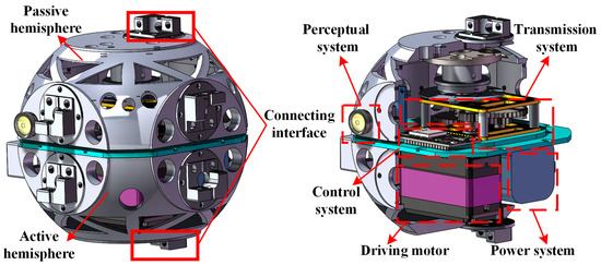
Figure 1.
Schematic diagram of the cellular space robot module.
The outer envelope of the cellular space robot module is spherical, and the module is divided into the active hemisphere and the passive hemisphere according to the different positions of the internal drive motors, and the passive hemisphere can do a circular motion around the axis of the driving hemisphere under the action of the internal drive source. The CSR has the complete toolset, which can be connected to the CSR’s module through the same mechanical connection interfaces to meet the needs of different on-orbit mission requirements and expand the working range of the CSR.
Different from the traditional self-reconfigurable robot architecture, the CSR’s working architecture consists of three levels: module level, organ level, and robot level. The module level is the smallest constituent unit of the system, and its functions mainly include perception, decision-making, and execution. The organ level is composed of multiple modules through topological connections, which is the smallest functional basic unit of the system oriented to behavior, and each organ is capable of realizing different behaviors composed of several motions. The robot level is the smallest mission unit of the system for the final realization of the target mission unit, composed of different organs. The robot can call upon organs with different execution functions to complete the mission.
As shown in Figure 2, the CSR module is formed into a 5-DOF tandem configuration by self-organization, which can be trained to achieve three-dimensional spatial motion of the end-effectors. As shown in Figure 2a, for the truss assemble task, the robot is reconfigured to form a two-armed robot by group-decision secondary reconfiguration, which improves the assembly efficiency and stability of the robot. As shown in Figure 2b, oriented to the on-orbit replaceable unit (ORU) transportation task, the 5-DOF organ is reconfigured secondary to form the quadruped robot, which is used to realize the robot’s motion capability in complex environments.
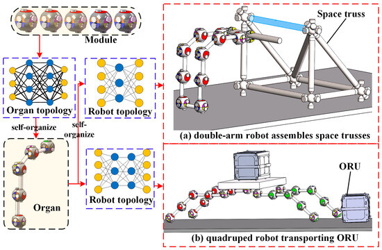
Figure 2.
Schematic diagram of CSR multi-level reconfiguration mechanism.
The module size and topology of the CSR are the influencing factors in the kinematic modeling of the CSR, and the structural dimensions of the CSR studied in this paper are shown in Figure 3.
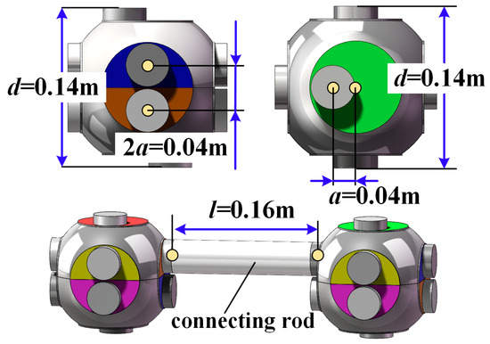
Figure 3.
Dimension schematic of cellular space robot structure.
2.2. The Kinematic Model of the CSR Module
The upper and lower hemispheres of the Cellular Space Robot (CSR) can be categorized into input and output hemispheres according to the different assembly positions. The input hemisphere is fixed to the base or other CSR module to realize the geometric position of the module, and the output hemisphere moves relative to the input hemisphere around its own axis under the action of the internal drive source.
As is shown in Figure 4, the center of the input hemisphere and the output hemisphere of the module- are designated by and , respectively, and both points coincide at the center of the module sphere. The input coordinate system is represented by , with its origin fixed at . The z-axis of the coordinate system is denoted by , and its direction coincides with the axis of the module joint. The x-axis of the coordinate system is denoted by , whose direction is parallel to the direction of the interface-1 axis of the module, and the y-axis of the coordinate system, is denoted by , which is determined by the right-hand rule.
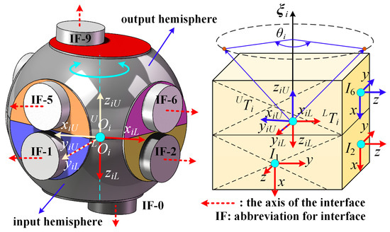
Figure 4.
Schematic of the kinematic model of the module.
The output coordinate system is represented by . In the initial state of module-i, the z-axis of the output coordinate system is denoted by , and the direction is on the same line and opposite to the z-axis of . The y-axis of the output coordinate system coincides with the y-axis of the input coordinate system , and the y-axis of the coordinate system is denoted by , which is determined by the right-hand rule.
The kinematic transformation between the output hemisphere relative to the input hemisphere can be expressed as . According to screw theory, the following equation holds:
where the denotes the pose transformation between the output coordinate system and the input coordinate system in the initial state () of the CSR. denotes the CSR’s module rotation angle, and denotes the rotation ordinate of the joint axis represented by the output coordinate system.
For the CSR module (as is shown in Figure 4), the rotational coordinate of the joint axis represented by the output coordinate system of the module is . The kinematic equation of the CSR module can be expressed as follows
where represents the rotation angle of the output coordinate system relative to the z-axis of the input coordinate system in the initial state, which is .
The interface distribution of the CSR module is shown in Figure 4. The interface-j coordinate system of the module is denoted by . The origin of the interface coordinate system is located at the center of the interface plane denoted by , and the z-axis of the coordinate system is directed outward along its own interface axis.
As is shown in Figure 5a, the interface coordinate system I0–I4 is solidly connected to the input coordinate system , and the x-axis direction of the I1–I4 interface coordinate system is the same as the z-axis direction of the input coordinate system , the x-axis direction of the I0 interface is the same as the y-axis direction of the input coordinate system . As shown in Figure 5b, the interface coordinate system I5–I9 is solidly connected to the output coordinate system, and the x-axis direction of the I5–I8 interface coordinate system is the same as the z-axis direction of the output coordinate system , and the y-axis direction of the I9 interface is the same as the x-axis direction of the input coordinate system . The y-axis of the interface coordinate system is determined by the right-hand rule. The pose-transformation relationship between the interface coordinate system and its fixed input or output coordinate system is a constant. In order to express the connection relationship between different modules of the CSR, a unified mathematical description of the rigid pose transformations in different interface coordinate systems and the central coordinate system is required.
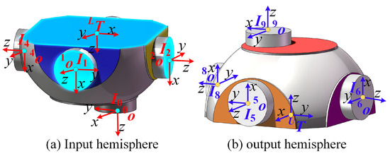
Figure 5.
CSR’s interface coordinate system.
The pose-transformation of the interface coordinate system relative to the rigidly fixed center coordinate system ( or ) is performed in the order of rotation followed by translation. For the input hemisphere of the CSR, the pose transformation of the connection interface-j relative to the input coordinate system is provided by the following equation.
For the output hemisphere, the pose transformation of the connection interface-j relative to the output coordinate system is provided by the following equation.
where denotes the translation transformation performed after the rotational transformation. The translation transformations are the same for all connected interfaces since the interface coordinate system posture remains constant after the rotational transformation. From the geometric relationship, the following equation holds:
It is assumed that the input hemisphere of the module-i of the CSR is assembled in the assembly position for localization using interface-j, and the output hemisphere of the module is connected to other module by using interface-k for the external function output. The CSR module is isomorphic, and the motion passes from the input interface-j to the output interface-k eventually. The pose transformation of the input interface-j coordinate system to the input coordinate system is , and the pose transformation of the output interface-k coordinate system to the output coordinate system is . Therefore, the kinematic equation of the CSR’s module when the input interface is interface-j, the output interface is interface-k and the rotation angle is , which can be expressed by the following equation.
The four connection methods for the inter-module connection of space cell robots are shown in Figure 6. The CSR determined with Equation (6) is completely isomorphic, and the connecting rod is installed between the two modules of the CSR. We assume that the origin of the interface- coordinate system of module-i is and the origin of the interface- coordinate system of module- is . Different connection methods between the modules have the same pose transformations, which are expressed in terms of the positional transformations , and the following equation holds
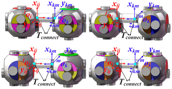
Figure 6.
CSR module connection method.
Based on the geometry of the module shown in Figure 3, a = 0.02 m, , and , then the actual dimension values of Equations (5) and (7) are shown in the following equation:
Therefore,, , and are constants. After the two modules of the cellular space robot are rigidly connected by connecting rods, the positional transformation between the module inputs is denoted by, and the robot joint angles are denoted by, the kinematic equations of the two modules after connection are:
3. Multi-Level Topological Description of CSR
During topological self-organization, the CSR is reconfigured at multiple levels according to module–organ–robot to form different functional organizations. The hierarchical organization of CSR at each level requires an accurate representation of the connections. In order to solve the multilevel topology description problem, this paper adopts graph theory to express the multilevel topology reachable information and assembly information.
3.1. CSR Multi-Level Topology Reachability Analysis
Definition 1.
The topological organization of the CSR can be denoted by a directed graph , where the vertex set denotes the node elements in the topological organization. In the organ organization, the vertex element denotes the CSR module , and in the robot organization, the vertex element denotes the CSR’s organ module . The edge set represents the connection relationships between the vertex elements of the CSR’s topological organization. In the organ level of organization, the edge denotes the connection relationship between two modules of the CSR, and in the robot level of organization, the edge denotes the connection relationship between two organs of the CSR. Based on graph theory, the topological organization of the CSR is represented using the adjacency matrix organized at different levels. The entry in row and column of is provided as:
The topological relationships before and after the evolution of the organ configuration of the CSR are shown in Figure 7. In the directed graph , the represents the modules of the CSR, and the represents the connection relationship between the modules. The topological adjacency matrix before and after the evolution of the CSR’s organ configuration is and , respectively.
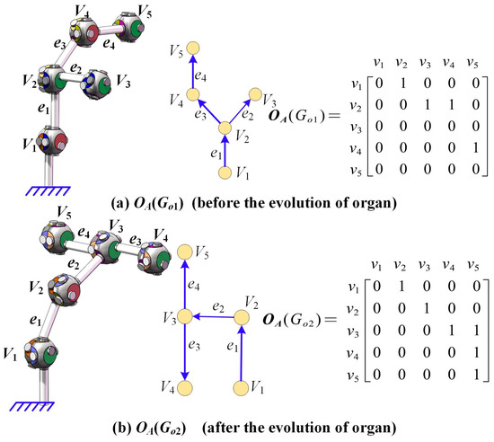
Figure 7.
Description of the CSR organ level topology.
At the robot level, the CSR is formed from a number of different organs connected according to a topology that passes through the robot level. As is shown in Figure 8, the robot is formed by three organs connected according to the topology of the robot level. In the directed graph , the represents the organs of the CSR, and the represents the connection relationship between the organs. The topological adjacency matrix before and after the evolution of the CSR’s robot configuration is and , respectively.
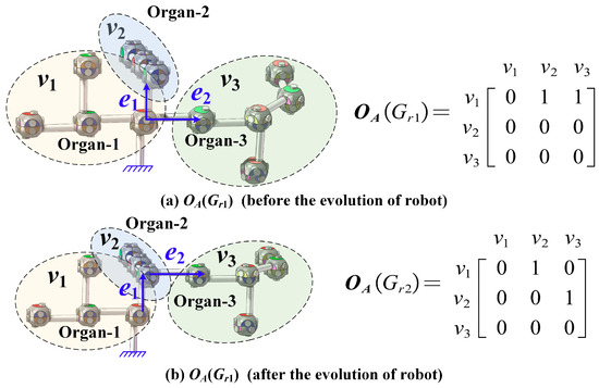
Figure 8.
Description of the CSR robot level topology.
It can be seen that the topological connections at different levels of the CSR can be uniquely expressed by the adjacency matrix of its directed graph. Motion pathways are the basis of kinematic modeling of the CSR, and based on the mathematical properties of graph theory and adjacency matrix, the algorithmic flow for constructing the pathway matrix is as follows:
Taking the robot configurations in Figure 7a and Figure 8a as an example, the path-relation matrices ( and ) obtained by using the pathway matrix computation method are, respectively:
These results are consistent with the robot-directed graph. This verifies the correctness of the access matrix algorithm for multilevel topological connectivity matrices proposed in this paper.
3.2. CSR Multi-Level Assembly Representation
Definition 2.
The CSR’s organ assembly matrix is denoted by , where is a directed graph of the topology of the organ organization, the is an dimensional matrix, and the is the number of CSR modules that make up the organ.
- 1.
- The is used to denote the entry of the CSR’s organ assembly matrix, the represents the assembly relationship of module- when the CSR’s module- points to module- along the directed-graph pathway;
- 2.
- , where k, l are the input and output interfaces of the CSR module-i respectively;
- 3.
- When is the starting point of the directed graph path, there is , and the represents the CSR module assembled and connected to the base by using interface-; when is the ending point of the directed graph path , there is holds and represents the external output motion of the CSR’s module-i using interface-l.
The entry in row and column of is provided as:
Taking the two-branched CSR organ as an example. As shown in Figure 9a, before the evolution of the organ configuration, the CSR’s organ assembly matrix can be represented by . As shown in Figure 9b, after the evolution of the organ configuration, the CSR’s organ configuration keeps the connection relationship between modules unchanged only the assembly relationship between modules is changed to obtain the evolved organ assembly matrix . It can be seen from Figure 9 that the organ assembly matrix proposed in this paper can accurately describe the assembly relationships before and after the organ evolution.
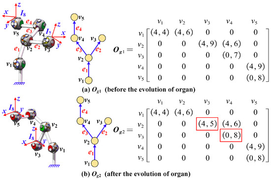
Figure 9.
Description of the CSR organ level 3D assembly information.
During the reconfiguration of the robot level, to ensure the integrality of the functional migration of the organ, the organ utilizes its own Module 1 to integrate with other robot organizations.
Definition 3.
The CSR’s robot assembly matrix is denoted by , where is a directed graph of the topology of the robot organization, the is an dimensional matrix, and the is the number of CSR organs that make up the robot.
- 1.
- The is used to denote the entry of the CSR’s robot assembly matrix , the represents the assembly relationship of organ-i when the CSR organ- points to organ-j along the directed graph pathway;
- 2.
- , where k denotes that the CSR’s organ-i is connected to organ-j by using the module-k, the l denotes that organ-i uses the interface-l for external output, and m denotes that the organ-j is connected to organ-i using the interface-m of the module-1;
- 3.
- When is the endpoint of the path in the directed graph of the robot level, the conditions and hold, representing that the module- of the CSR’s organ-i uses interface-m to output motion externally.
Taking the multi-branch robot configuration as an example, as shown in Figure 8, the robot organization of CSR is formed by the connection of , , . The assembly matrix of the robot before and after the change of topology is denoted by and , respectively. It can be seen from Figure 10 that the robot assembly matrix uniquely and accurately expresses the CSR’s configurations before and after migration.
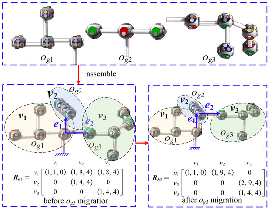
Figure 10.
Description of the CSR robot level 3D assembly information.
4. Multilevel Kinematic Modeling of CSR
4.1. Organ-Level Kinematic Model
Assuming that the CSR’s organ consists of modules connected by the connecting interfaces, the organ-rotation angle can be denoted as , where the represents the rotation angle of module-i. The kinematic equations for each module of the CSR can be obtained from Equation (6), . The pose-transformation matrix of the connection between the CSR modules is . From Equation (9), the kinematic equation for the n-module robot chain organ of the CSR is shown below:
For the q-path organs of the CSR, the organ assembly matrix is . The pathway matrix is obtained from the pathway Algorithm 1. The module index list of the pathway matrix is denoted by and has the following definition:
where represents the module list index of the p-th pathway of the organ. For example, if the p-th pathway of CSR’s organ composed of five modules is , then the module index list is .
| Algorithm 1: Calculate the path matrix |
| Input: The topological-directed graph of the robot Output: Pathway matrix for topological organization
|
The non-zero elements in the organ assembly matrix of the CSR are replaced with 1 to obtain the CSR’s extended adjacency matrix . For the multi-branch CSR organ composed of nodules, this paper uses the organ module kinematics matrix to express the kinematic equations of the module in the pathways. is an entry in , and denotes the kinematic equation of module-i when module-j is connected to module-i.
where is the angle of rotation of each module of the organ. The is an entry in ; if , that means module-j is connected to module-i. The is the CSR’s organ assembly matrix, and is an entry in the that represents the assembly relationship between module-i to module-j in the pathway. In the pathway from module-i to module-j, and denote the input and output interfaces of module-i, respectively.
For the CSR organ with multiple pathways, the pathway matrix can be used to divide the multi-branched into the CSR’s organ into multiple chained pathways. As is shown in Figure 11, the robot module-1 is fixed to the base coordinate system by means of a connecting rod. The CSR organ consists of pathways, where the pathway-p consists of modules, and the module serial number can be obtained from the module index list . is the rotation angle of the modules in the pathway-p. Then,
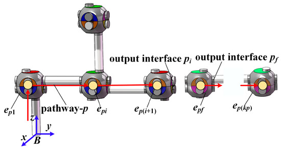
Figure 11.
Schematic diagram of CSR organ pathway.
With the output interface of the f-th module of path-p being pf, we can also obtain the kinematic equations for the output coordinate system of the h-th module in path-p:
For the CSR organ with pathways, the is the rotation angle of each module of the organ. The denotes the rotation angle of each module of the pathway-p, then . The kinematic equation of the CSR organ with pathways can be derived from Equation (13):
Once the organ assembly matrix of the CSR organ is obtained, the kinematic model of the CSR organ can be automatically generated according to Equation (18). The kinematic algorithm for the CSR’s organ is provided in Algorithm 2.
| Algorithm 2: Kinematic algorithms for CSR organ |
| Input: The organ assembly matrix , the rotation angle of modules ; Output: The pose of the output interface coordinate system of the end-of-organ module relative to the base coordinate system , ; Matrix of the output coordinate system of the modules of the organ, .
|
4.2. Robot-Level Kinematic Model
The organ kinematics algorithm can establish the CSR organ kinematics model and provide mathematical models for motion control and intelligent decision-making for organ functions. Once the organ functions are established, the robotic level controller can select organs with different execution functions for secondary reconfiguration to customize the topological configuration according to the on-orbit operational missions. Let the robot level consist of organs and the assembly matrix of the robot level is denoted by . The pathway matrix for the robot level can be obtained from the pathway Algorithm 1. The organ index list of the pathway matrix of the robot is denoted by . Let a robot consist of t pathways, where pathway-s consists of organs and the organ serial number can be obtained from the pathway index list, .
where the denotes the organ serial number of the i-th organ in the pathway-s.
The kinematic equations for each organ of the robot level are represented by , and the number of organ pathways for each organ is . Then, the kinematic equations for each organ can be represented by the following equation.
where the number of pathways of organ-i is denoted by , and represents the module rotation angle of the j-th pathway in organ-i.
As is shown in Figure 12, the module-1 of the robot’s organ-1 is connected to the base coordinate system by means of a connecting rod. The organ index list of the pathway-s of the robot level is . The and are two adjacent organs on the pathway-s of the robot, respectively. It is assumed that is connected to the module-k of the organ . In the organ , the module-k of the is located on Pathway of the organ . The () denotes the number of the module under pathway-h in organ . We assume that module-k is numbered in the pathway-h. The kinematic equation for the coordinate system of the output interface of the module-k of organ on the pathway-h are as follows:
where is the connection transformation between the two modules of the CSR. is the organ module kinematics matrix of the organ . denotes the entry in row and column of . The indicates the angle of rotation of each module in the organ .
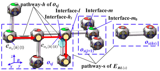
Figure 12.
Schematic diagram of CSR robot pathway.
At the organ level, it is assumed that in the pathway-h of the organ , module-k takes interface-hl as an output interface to the next module. The organ takes interface-l as an output interface to connect the interface-m of the organ . The coordinate transformations between the output coordinate system of the module-k of organ and interface-hl, and interface-l of the organ are and respectively, where the interface-l can be indexed using the assembly matrix of .
The kinematic equations for the module-k output coordinate system of the organ are shown in Equation (23), and the can be obtained from Algorithm 2.
From Equation (6), the kinematic equations of the organ interface-l are expressed as follows:
It is assumed that at the organ level, uses the interface-m0 of its own module-1 as an input interface, while it uses the interface-m of module-1 as an input interface when connecting to the . Then interface-m0 and interface-m can be indexed by the assembly matrix.
After organ is connected to organ on the robot pathway-, organ adds a kinematic model of organ to the pathway-h of the . The organ increases the organ kinematic model of due to connected to , so the CSR’s kinematic equations are in recursive form. The robot-level kinematics equations on pathway- have the following recursive relationship:
According to the conformational features of the CSR, all pathways starting point at organ-1 (). It is assumed that, on path-s, organ is connected to organ via the interface-l1 of module-k1. Then, the kinematic equation of the pathway cellular space robot can be obtained from the following equation:
From Equations (26) and (27), the equations of kinematics of the CSR equipped with t pathways are shown below:
5. Simulation Verification
Once the multi-level assembly matrix of cellular space robots is known, the kinematic algorithm can automatically generate the kinematics model. In terms of validation methods for the kinematic model, the current researchers [25,28] commonly use numerical simulation as a comparison algorithm to validate models. In order to exclude the influence of other factors on the verification of the kinematic model, the current studies [29,30] verify the kinematic model under ideal conditions without considering the dynamic characteristics of the robot-control system. In this paper, without considering the dynamic characteristics of the robot system, we use vrep to conduct numerical simulations to validate the kinematic models of robot organizations at various levels. The geometry of the CSR’ module is shown in Figure 3 and Equation (8).
5.1. Verification of Organ-Level Kinematic Algorithm
To verify the kinematic model of the organ level, without loss of generality, this paper selects organ-1 as shown in Figure 13 as an illustrative example. The vertex and edge sets of organ-1 are and , respectively.
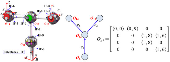
Figure 13.
Description of the 3D assembly information for organ-1.
For organ-1, according to Algorithms 1 and 2, the pathway matrix and the module kinematics matrix of organ-1 can be solved, where is the joint angle of each module in organ-1, . The pathway matrix and module kinematics matrix for organ-1 are shown below.

Table 1.
Table entries of non-I (unit matrices) of .
According to Algorithm 2, we can obtain the kinematic equations for the branch-end coordinate systems and of the CSR and the base coordinate system of the organ-1 as shown below.
In the computational example of the organ level, we obtained the kinematic equation for organ-1 by using the multi-level kinematic algorithm. Without loss of generality, the rotation angles of each module of the CSR as the functions of time are . The effectiveness of the proposed algorithm is verified by comparing the displacement curves of the x, y, z axis of the branches ends of organ-1 in the base coordinate system obtained from this paper’s algorithm and Vrep simulation, and the simulation results are shown in Figure 14.
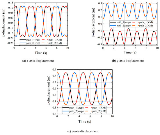
Figure 14.
Displacement of the end of organ-1 pathway.
As shown in Figure 14, the solid lines in the figure represent the displacement curves of the two branch ends of organ-1 obtained using Vrep. The black curve represents the displacement curve of the end of pathway-1 of organ-1, while the blue line represents the displacement curve of the end of pathway-2 of organ-1. The dashed lines represent the displacement curves solved using the multi-level kinematic algorithm (MLK) proposed in this paper. The red curve represents the displacement curve of the end of pathway-1 of organ-1, and the orange line represents the displacement curve of the end of pathway-2 of organ-1. From the Figure 14, it can be seen that the multi-level kinematic algorithm (MLK) proposed in this paper overlaps with the displacement curves solved by the Vrep. This result indicates that the kinematic equations obtained in this paper are equivalent to the kinematic equations of the Vrep and proves the effectiveness of the robot kinematics algorithm.
5.2. Verification of Robot-Level Kinematic Algorithm
To verify the correctness of the kinematic model at the robot level, we use the different configuration robots which composed of multiple organ as the representative examples. The robots are assembled from three different organs: organ-1 (o1), organ-2 (o2), and organ-3 (o3). As is shown in Figure 13, the configuration and assembly relation matrix for organ-1 have already been provided. The topological directed graphs for organ-2 (o2) and organ-3 (o3) are represented by and , respectively, with vertex sets o2 = {o21, o22, o23} and . The assembly matrix for organ-2 () and organ-3 () is shown in Figure 15. The configuration of the robots is shown in Figure 16 and Figure 17.
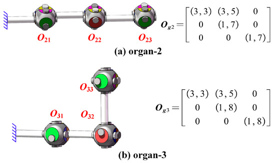
Figure 15.
Schematic of the 3D assembly information for organ-2 and organ-3.
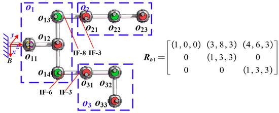
Figure 16.
3D assembly information for robot-1 (before organ migration).
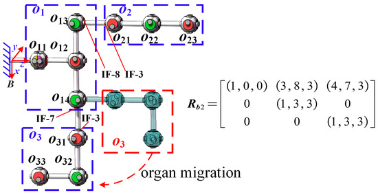
Figure 17.
Three-dimensional assembly information for robot-1 (after organ migration).
According to Algorithm 2, the kinematic equations for organs-2 and organ-3 can be obtained:
where represents the element in the of organ-.
The robot-1 formed by connecting organ-1 (o1), organ-2 (o2), and organ-3 (o3), as well as the robot-1 assembly matrix , is shown in Figure 16.
According to Algorithm 3, the pathway matrix for the robot level is as follows.
| Algorithm 3: Kinematic algorithms for CSR robot |
|
From Equation (32), the robot-1 consists of two pathways (p1, p2). As is shown in Figure 16, the module-3 (o13) of organ-1 (o1) is connected to organ-2 (o2) to form pathway-p1, and module-4 (o14) of organ-1 (o1) is connected to organ-3 (o3) to form pathway-p2. The assembly matrix of o1 is shown in Figure 13, and its module kinematics matrix is shown in Equation (29), while the kinematic equations for each module of o1 are shown in Table 1. By means of Algorithm 3, we can obtain the kinematic equations for the output coordinate system of module-3 (o13) and module-4 (o14) of o1, denoted by and , respectively.
According to Equation (24) and Figure 16, the coordinate transformations between the interface coordinate systems and the base coordinate system at the connections of o1 with o2 and o3 are denoted as and , respectively.
Based on the assembly relationship shown in Figure 13, Figure 15 and Figure 16, the kinematic equations of the robot-1 can be obtained by Algorithm 3 as follows:
During the configuration evolution of the CSR at the robot level, the relative positions and assembly relationships among the organs undergo transformation, leading to changes in the robot’s functional capabilities. To adapt to space missions, organ-3 of robot-1 migrates to form robot-2. After conformational evolution at the robot level, the assembly matrix of the CSR is shown in Figure 17.
According to Equation (24) and Figure 17, the coordinate transformations between the interface coordinate systems and the base coordinate system at the connections of o1 with o2 and o3 are denoted as and , respectively
Based on the assembly relationship shown in Figure 13, Figure 15 and Figure 17, the kinematic equations of the robot can be obtained by Algorithm 3 as follows:
Without loss of generality, the rotation angle functions of the organ modules of the CSR are set as shown in Equation (38). In this paper, we select two examples of robots before and after configuration change and set the numerical simulation time to 10 s. To verify the effectiveness of the proposed algorithm, we compare the displacement curves of the ends of the robot branches along the x, y, and z axes in the base coordinate system obtained from the muti-level kinematic algorithm (MLK). The simulation results are shown in Figure 18 below.
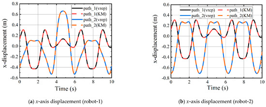
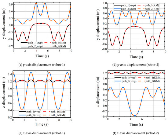
Figure 18.
Displacement of the end of the robot pathway.
As is shown in Figure 16 and Figure 17, only the assembly relationship of organ-3 changes, while the number of robot pathways remains unchanged. As is shown in Figure 18 below, the (a), (c), and (e) show the displacement curves of the ends of the robot before the change of configuration in the base coordinate system, and the (a), (c), and (e) show the displacement curves of the ends of the robot after the change of configuration in the base coordinate system. The black curve represents the displacement curve of the end of pathway-1 of the robot, while the blue line represents the displacement curve of the end of pathway-2 of the robot. The dashed lines represent the displacement curves solved using the multi-level kinematic algorithm (MLK) proposed in this paper. The red curve represents the displacement curve of the end of pathway-1 of the robot, and the orange line represents the displacement curve of the end of pathway-2 of the robot. From Figure 18, it can be seen that the multi-level kinematic algorithm (MLK) proposed in this paper overlaps with the displacement curves solved by the Vrep. This result indicates that the kinematic equations obtained in this paper are equivalent to the kinematic equations of Vrep and proves the effectiveness of the robot kinematics algorithm.
6. Conclusions
Aiming at the multi-task demand of on-orbit service, this paper proposes a new isomorphic self-organizing cellular space robot. Based on the functional characteristics of the cellular space robot, we propose a multilevel reconfiguration mechanism using the group effect and establish a self-organizing behavior mechanism for the cellular space robot. Compared with the traditional self-reconfigurable robot, the multilevel reconfiguration mechanism proposed in this paper can reduce the configuration optimization space and improve the ability of cellular space robots to operate in orbit.
In order to accurately describe the topological relationships in the self-organizing process of the CSR, this paper proposes a multilevel topological description method based on graph theory, which accurately describes the three-dimensional spatial assembly relationships of the multilevel organization of cellular space robots. This paper also proposes a multilevel pathway-solving algorithm to accurately describe the reachability information between elements in the multilevel robot organization, which provides theoretical support for later kinematic modeling.
Finally, this paper proposes a multilevel kinematic modeling method, which considers the functions and multilevel topological relationships of modules, organs, and robots, hierarchically models the kinematic properties of each level and accurately describes the motion-transfer relationships among the levels through screw theory. The method separates the multilevel topology from the kinematic model, which can provide a theoretical basis for the optimization of multilevel configurations of the CSR. In order to verify the effectiveness of the kinematic algorithm, we compare the method proposed in this paper with the results of simulation software, and the results show the correctness of this paper’s algorithm. Compared with the traditional algorithm, the algorithm in this paper only needs to update part of the assembly relationship after organ migration, which significantly simplifies the kinematic modeling operation and improves the efficiency of kinematic computation.
Author Contributions
Methodology, X.L.; Software and programing, X.L., X.Z. and J.D.; Writing—original draft preparation, X.L. and S.W.; Writing—review and editing, B.Y., H.G., Z.L. (Zhaoxu Liu) and Z.L. (Zhichao Li); Project administration, B.Y.; Funding acquisition, B.Y. and H.G. All authors have read and agreed to the published version of the manuscript. All authors participated in and completed the proofreading of the paper.
Funding
This work is supported by the National Natural Science Foundation of China under Grant Nos. 52175082 and U23B20105, the Natural Science Foundation of Shandong Province under Grant No. ZR2021ME025.
Data Availability Statement
The data presented in this study are available on request from the corresponding author due to author’s privacy and ethical restrictions.
Conflicts of Interest
The authors declare that they have no known competing financial interests or personal relationships that could have appeared to influence the work reported in this paper.
References
- Li, W.-J.; Cheng, D.-Y.; Liu, X.-G.; Wang, Y.-B.; Shi, W.-H.; Tang, Z.-X.; Gao, F.; Zeng, F.-M.; Chai, H.-Y.; Luo, W.-B.; et al. On-orbit service (OOS) of spacecraft: A review of engineering developments. Prog. Aerosp. Sci. 2019, 108, 32–120. [Google Scholar] [CrossRef]
- Qiu, H. Review of deployable sar antenna structures of spacecraft. J. Astronaut. 2021, 42, 1197. [Google Scholar]
- Ding, X.; Wang, Y.; Wang, Y.; Xu, K. A review of structures, verification, and calibration technologies of space robotic systems for on-orbit servicing. Sci. China Technol. Sci. 2021, 64, 462–480. [Google Scholar] [CrossRef]
- Gao, L.; Cordova, G.; Danielson, C.; Fierro, R. Autonomous Multi-Robot Servicing for Spacecraft Operation Extension. In Proceedings of the 2023 IEEE/RSJ International Conference on Intelligent Robots and Systems (IROS), Michigan, MI, USA, 1–5 October 2023; pp. 10729–10735. [Google Scholar]
- Flores-Abad, A.; Ma, O.; Pham, K.; Ulrich, S. A review of space robotics technologies for on-orbit servicing. Prog. Aerosp. Sci. 2014, 68, 1–26. [Google Scholar] [CrossRef]
- Chang, H.; Huang, P.; Wang, M.; Meng, Z. Distributed control allocation for cellular space robots in takeover control. Acta Aeronaut. Astronaut. Sin. 2016, 37, 2864–2873. [Google Scholar] [CrossRef]
- Zhao, H.; Zhao, Y.; Tian, H.; An, D.X. Key Techniques and Applications of Space Cellular Robotic System. J. Astronaut. 2018, 39, 1071–1080. [Google Scholar] [CrossRef]
- Ding, H. Uniform Topological Representation Model of Planar Mechanisms and Isomorphism Identification. Chin. J. Mech. Eng. 2009, 45, 99–103. [Google Scholar] [CrossRef]
- Chu, J.; Zou, Y. An algorithm for structural synthesis of planar simple and multiple joint kinematic chains. Proc. Inst. Mech. Eng. Part C J. Mech. Eng. Sci. 2013, 228, 2178–2192. [Google Scholar] [CrossRef]
- Dong, K.; Li, D.; Kong, X. Representation of planar kinematic chains with multiple joints based on a modified graph and isomorphism identification. Mech. Mach. Theory 2022, 172, 104793. [Google Scholar] [CrossRef]
- Eldershaw, C.; Yim, M.H.; Duff, D.; Roufas, K.; Zhang, Y. Robotics for Future Land Warfare: Modular Self Reconfigurable Robots. In Seminar and Workshop, Defence Science Technology Organisation, Engineering; Environmental Science: Adelaide, Australia, 2002. [Google Scholar]
- Yim, M.; Roufas, K.; Duff, D.; Zhang, Y.; Eldershaw, C.; Homans, S. Modular Reconfigurable Robots in Space Applications. Auton. Robot. 2003, 14, 225–237. [Google Scholar] [CrossRef]
- Paredis, C.J.J.; Brown, H.B.; Khosla, P.K. A rapidly deployable manipulator system. In Proceedings of the IEEE International Conference on Robotics and Automation, Minneapolis, MN, USA, 22–28 April 1996; Volume 1432, pp. 1434–1439. [Google Scholar]
- Acaccia, G.; Bruzzone, L.; Razzoli, R. A modular robotic system for industrial applications. Assem. Autom. 2008, 28, 151–162. [Google Scholar] [CrossRef]
- Jie, Z.; Xindan, C.; Yanhe, Z.; Shufeng, T. A new self-reconfigurable modular robotic system UBot: Multi-mode locomotion and self-reconfiguration. In Proceedings of the 2011 IEEE International Conference on Robotics and Automation, Shanghai, China, 9–13 May 2011; pp. 1020–1025. [Google Scholar]
- Zhao, J.; Cui, X.; Zhu, Y.; Tang, S. UBot: A new reconfigurable modular robotic system with multimode locomotion ability. Ind. Robot Int. J. 2012, 39, 178–190. [Google Scholar] [CrossRef]
- Zhu, Y.; Zhao, J.; Cui, X.; Wang, X.; Tang, S.; Zhang, X.; Yin, J. Design and implementation of UBot: A modular Self-Reconfigurable Robot. In Proceedings of the 2013 IEEE International Conference on Mechatronics and Automation, Takamatsu, Kagawa, Japan, 4–7 August 2013; pp. 1217–1222. [Google Scholar]
- Liu, C.; Yim, M. Configuration Recognition with Distributed Information for Modular Robots. In Robotics Research; Springer International Publishing: Cham, Switzerland, 2020; pp. 967–983. [Google Scholar]
- Liu, C.; Lin, Q.; Kim, H.; Yim, M. SMORES-EP, a modular robot with parallel self-assembly. Auton. Robot. 2023, 47, 211–228. [Google Scholar] [CrossRef]
- Chen, I.M.; Guilin, Y. Configuration independent kinematics for modular robots. In Proceedings of the IEEE International Conference on Robotics and Automation, Minneapolis, MN, USA, 22–28 April 1996; Volume 1442, pp. 1440–1445. [Google Scholar]
- Hou, F.; Shen, W.-M. Graph-based optimal reconfiguration planning for self-reconfigurable robots. Robot. Auton. Syst. 2014, 62, 1047–1059. [Google Scholar] [CrossRef]
- Zhao, J.; Tang, S.F.; Zhu, Y.; Xindan, C. Topological description method of UBot self-reconfigurable robot. J. Harbin Instit. Tech. 2011, 43, 46–49+55. [Google Scholar]
- Thakker, R.; Kamat, A.; Bharambe, S.; Chiddarwar, S.; Bhurchandi, K.M. ReBiS-Reconfigurable Bipedal Snake robot. In Proceedings of the 2014 IEEE/RSJ International Conference on Intelligent Robots and Systems, Illinois, IL, USA, 14–18 September 2014; pp. 309–314. [Google Scholar]
- Bi, Z.M.; Gruver, W.A.; Zhang, W.J.; Lang, S.Y.T. Automated modeling of modular robotic configurations. Robot. Auton. Syst. 2006, 54, 1015–1025. [Google Scholar] [CrossRef]
- Li, Y.; Zhu, S.; Wang, Z.; Zhang, L.M.; Ma, X.; Cui, Z. The Kinematics Analysis of a Novel Self-Reconfigurable Modular Robot Based on Screw Theory. DEStech Trans. Eng. Technol. Res. 2017. [Google Scholar] [CrossRef] [PubMed]
- Kelmar, L.; Khosla, P.K. Automatic generation of kinematics for a reconfigurable modular manipulator system. In Proceedings of the 1988 IEEE International Conference on Robotics and Automation, Philadelphia, PA, USA, 24–29 April 1988; Volume 662, pp. 663–668. [Google Scholar]
- You, B. Gait Analysis of Cellular Space Robot for On Orbit Climbing Truss# br. J. Astronaut. 2020, 41, 521. [Google Scholar]
- Liu, X.; You, B.; Wang, R.; Zhao, Y.; Wei, C.; An, D. Multi-Branch Cellular Space Robot Mechanism Design and Climbing Behavior Research. J. Mech. Robot. 2023, 15, 051016. [Google Scholar] [CrossRef]
- Pan, X.; Wang, H.; Jiang, Y.; Xiao, J. Automatic kinematic modelling of a modular reconfigurable robot. Trans. Inst. Meas. Control 2012, 35, 922–932. [Google Scholar] [CrossRef]
- Zhang, T.; Du, Q.; Yang, G.; Wang, C.; Chen, C.; Zhang, C.; Chen, S.; Fang, Z. Assembly Configuration Representation and Kinematic Modeling for Modular Reconfigurable Robots Based on Graph Theory. Symmetry 2022, 14, 433. [Google Scholar] [CrossRef]
Disclaimer/Publisher’s Note: The statements, opinions and data contained in all publications are solely those of the individual author(s) and contributor(s) and not of MDPI and/or the editor(s). MDPI and/or the editor(s) disclaim responsibility for any injury to people or property resulting from any ideas, methods, instructions or products referred to in the content. |
© 2024 by the authors. Licensee MDPI, Basel, Switzerland. This article is an open access article distributed under the terms and conditions of the Creative Commons Attribution (CC BY) license (https://creativecommons.org/licenses/by/4.0/).