Abstract
An electrical motors, together with its appropriate drive system, is one of the most important elements of electromobility. In recent years, there has been a particular interest by academic researchers and engineers in permanent-magnet motors (PMSMs) in various applications, such as electric vehicles, Unmanned Aerial Vehicles (UAVs), elevator systems, etc., as the main source of drive transmission. Nowadays, the elevator industry, with the evolution of magnetic materials, has turned to gearless PMSMs over geared induction motors (IMs). One of the most important elements that is given special emphasis in these applications is proper motor design in consideration of the weight and speed of the chamber to be served during operation. This paper presents a design of a high-efficiency PMSM, in which finite elements analysis (FEA) and the study of the lift operating cycle provided useful conclusions on the magnetic field of the machine in different operating states. In addition, a simulated model was compared with experimental results of test operations. Furthermore, the drive system also required the use of appropriate electrical power and controls to drive the PMSM. Especially in elevator applications, the control of the motor speed by the variable voltage variable frequency technique (VVVF) is the most common technology used to avoid endangering the safety of the passengers. Thus, suitable speed and current controllers were used for this purpose. In our research, we focused on studying different control techniques using a suitable inverter to compare the system operation in each case studied.
1. Introduction
Electromobility is undoubtedly one of the most crucial issues in the energy sectors, as there is research interest in application techniques that are as environmentally friendly as possible [1]. Particular emphasis is placed mainly on the drive system, in which electric motors together with the drive system (inverter) are the main parts required for proper operation [2]. By being integrated into a wide range of industrial technologies, electric motors have a significant focus due to the electrification of various drive systems, such as electric vehicles, aircraft, ships, etc., in order to become more efficient and meet the requirements of users [3].
Immediate and fast movements have led to the implementation of lifting systems to ensure the safe transportation of users in any building. As lifting systems needs increase, it is very important to create suitable elevator systems based on alternative energy sources, such as renewable energy [4], that are efficient and provide comfort for the transportation of passengers [5]. Elevator technology focuses on designs for use in buildings that are energy efficient according to international rules and standards [6]. The proper operation of both the machine and the system relies on driving the motor overall with appropriate power electronics [7]. Modern inverters have the ability to program the elevator movement in order to achieve greater energy savings, depending on their settings, and reduce vibrations during the movement of the chamber [8]. Proper driving of the elevator requires suitable control of both the motor and the system. Several research studies have focused on the application of various controller design techniques [9].
In addition, the evolution of the design and the optimization of electric motors and the power electronics for driving them has made permanent magnet synchronous motors (PMSM) a suitable technology for elevator applications that depending on their design and functional characteristics, can be adapted to various types of chambers. This paper focuses on the design and high-performance capabilities of a PMSM motor, especially for its application in elevator lifting systems that have special requirements for high torque and low speed. Elevator lifting systems are widely used in urban installations and their safety, robustness and low energy consumption during motion are points of interest for lift designers and manufacturers.
The remainder of this paper is organized as follow: Section 2 provides information on the use of PMSMs in lifting applications and their advantages that make them a dominant technology over other categories of electric machines. Furthermore, Section 3 presents an analysis of the drive system, the basic parts of a mechanical lift and their influence on the overall operation of the system. It should be noted that for the design of the motor, its electrical and mechanical characteristics are used, a specific design methodology is followed based on a preliminary design analysis using finite element analysis (FEA) implemented in ANSYS Electromagnetics Suite Software 23 R1 Version 1, and the simulated results are compared with the experimental data of the elevator operation at various loads, which are presented in Section 4. Section 5 focuses on the analysis of the elevator duty cycle as well as the energy savings of the system using the VVVF technique. This technique relies on an appropriate inverter and elevator speed control. Therefore, in Section 6, various PMSM motor drive control techniques will be analyzed in order to select the optimal controller option using MATLAB R2023b. Finally, Section 7 summarizes the main conclusions drawn at both the simulated and experimental level and derived from the analyses of the above sections.
2. PMSM in Elevator Technology
Nowadays, the most common means of transportation and moving people in buildings is the use of electromechanical elevators, which are more reliable lifting systems than hydraulic elevators [10], and have the ability to cover long distances at high speeds. Their main advantage is due to their electric motor, which is the main means of transmission. The elevator industry bases the overall system design on control, safety systems, resistance to even extreme vibrations and economy [7].
Elevator companies manufacture smart elevators that are built in such a manner that they have precise control capabilities and a small number of sensors. A modern control method that is used as a means of transferring data and commands, even from long distances, is the use of PLCs [11,12] and microcontrollers [13]. In multistory buildings, lifts can achieve a nominal speed of 18 m/s. In these cases, in order to avoid severe jerking, an appropriate adjustment of the acceleration and deceleration rate is required in as smooth a manner as possible [14,15].
2.1. Permanent Magnet Synchronous Motor
Manufacturers have focused their research and development interest in the electric motor category, replacing traditional induction motors. Their most important advantages relate to the following:
- Efficiency. This is the main focus, as high efficiency is realized due to the magnetic field created by the magnets, so lower resistive losses and consequently lower copper losses are generated [16]. Generally, in conventional elevators we can find PMSMs with efficiencies up to 90% that are multi-pole, high speed and high torque [17]. Both the electrical and mechanical characteristics of the motor are adapted to the overall system of the elevator and the load it is required to serve. Also, PMSMs have a high-power density and a higher magnetic flux density in the gap than induction motors [18,19]. With their excellent dynamic performance, they have the capability of adjusting their speed in various operating situations. Moreover, in elevator applications, both the speed of the motor and the elevator can be varied according to the load [20].
- Energy savings. The gearless PMSMs with a transmission ratio of 1:1 present moderate mechanical losses and minimal energy and heat losses. This results in modern elevators achieving energy savings of 30–50% [21]. In addition, with the functional capabilities of the drive system, more energy can be saved by using regenerative braking. When the elevator load moves in the direction of gravity, the synchronous motors acts as a generator by returning part of the energy to the grid [22].
- Maintenance requirements. The condition monitoring of the gearbox minimizes friction, which results in heat losses and wear on the gears [23]. It is one of the main causes of breakdowns that can lead to the permanent destruction of the electric motor. In this case, maintenance costs are reduced as no additional lubricant costs are required [24].
Permanent magnet synchronous motors without a gearbox in elevators are divided into surface-mounted PM (SPR) and internal magnets (IPMs), depending on the positioning of the magnets inside the rotor. The advantages discussed above as well as the discovery of new rare earths for magnets, such as NdFeB and ferrite, make SPRs and IPMs attractive in both manufacturing and research fields [25,26]. Many research studies have shown that neodymium is a more attractive choice than ferrite, as it has superior residual induction and thermal resistance [27]. Its increased thermal coefficients make it more attractive, especially in elevators with a high rated speed, in which most thermal stresses occur [28]. The selection of a suitable rotor topology using special low-loss sheet metal minimizes core and copper losses [29]. The main advantages of using PMSMs are the elimination of rotor copper losses and the high starting torque [30].
2.2. Traction Elevator System
Figure 1 shows the typical traction system of an electromechanical lift with its main components. The mechanical features that we will focus on in this research are speed and torque. These two features will determine both the operating cycle of the elevator and the specifications of the PMSM. The speed depends on the height of the building and the maximum load that it is required to serve during its movement [31].
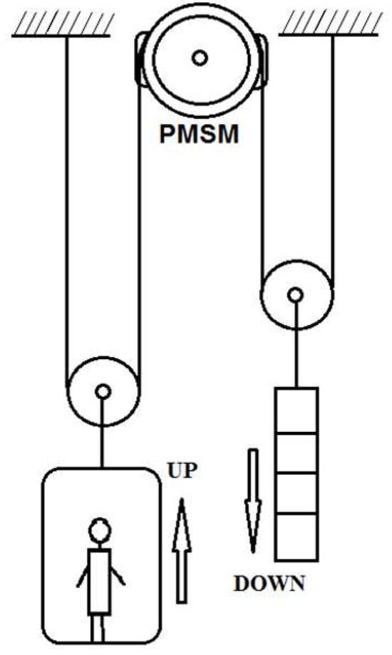
Figure 1.
Typical traction elevator system [26].
Similarly, the torque depends on the individual forces exerted on the chamber during its acceleration, i.e., chamber weight and load. One of the most important parts that reduces the energy consumed is the counterweight, as it is used to compensate for unweighting and some of the payload weight in order to reduce the torque requirements and increase the system efficiency [32].
The electrical motor drives a friction pulley, in which the lift car is on one side and the counterweight on the other side. However, the output power (kW) of the motor also depends on the load lifting speed, the active force, and the efficiency rate of the system [33]:
where F is the active force (kg), v is the velocity of the chamber (m/s) and n is the efficiency of the system.
The velocity (m/s) of the chamber is given by the following:
where D is the diameter of the friction pulley (m), K is the transmission ratio of the reducer and n is the nominal speed of the electric motor (rpm).
The angular speed (rad/s) of the electric motor is obtained as follows [34]:
where v is the coefficient of the suspension type (1:1), v is the velocity of the chamber (m/s) and is the radius of the drive pulley (m).
The equation for calculating the active force and the counterweight is as follows:
where M is the sum of the chamber weight, suspension frame, and cable (kg); is the nominal load (kg) and G is the weight of the counterweight (kg).
The load torque () for the movement of the lift car is calculated from [35]:
where is the counterweight mass (kg), is the total chamber mass with the load (kg), g is the force of gravity (m/), is the inertia of the motor rotor mass together with the friction pulley (kg), and is the radius of the friction pulley (m).
The mechanical motor torque () with the friction pulley is given as follows [36]:
where M is the mass of the chamber (kg), Q is the load (kg), G is the weight of the counterweight (kg), is the radius of the friction pulley (m), is the inertia of the motor rotor mass together with the friction pulley (kg), g is the force of gravity (m/), and a is the linear acceleration of the lift car (m/).
3. Design Procedure of the Permanent Magnet Synchronous Machine
The initial design of an electric machine provides a basic approximation of the required configuration. Field analysis then provides a detailed analysis of the magnetic field and can lead to a confirmation of the characteristics of the initial design or the need to improve the design parameters. Through the appropriate processing of the magnetic field distribution, quantities such as torque, force, losses, and current density for the case of the electric motor can be accurately calculated, while areas of the core that are saturated can be identified [37]. A careful study of these quantities can reveal any failures and deviations from the desired characteristics, leading to the identification of the causes of these results and enabling their correction.
The prediction of the magnetic field of the PMSM is one of the most important elements of its preliminary design. This prediction is based on finite element analysis characterized by accuracy and detailed numerical calculations of the parameters [38]. However, the simulation time is quite long and the computational cost is high (such as with 3D models), making it a time-consuming process [39].
3.1. Mathematical Model Electromagnetic Analysis
This section presents the mathematical background and the equations describing the PMSM magnetic field calculation. Electromagnetic analysis requires the solution of Maxwell’s equations for the given boundary conditions in order to accurately calculate the motor’s electromagnetic performance. The boundary conditions ensure the uniqueness of the solution within a solution region defined by the set of equations [40]. The equations below illustrate the parameters that must be satisfied [41,42]:
where H is the magnetic field intensity, B is the magnetic flux density, E is the electrical field intensity, D is the electric flux density, p is the electric charge density and t is the time.
The following equations describe the Gauss law, the Faraday law and the Biot–Savart–Laplace law. respectively [43]:
where I is the electric current and is the elementary length of the conductor.
Accurate PMSM design requires an appropriate choice of ferromagnetic material in the magnets. State-of-the art PMSM design technologies rely on the use of nonlinear materials, which are of research interest due to their magnetic properties determined by the B-H curve [44]. These technologies have the advantages of high speeds and loss reduction through low-cost cores. Some recent characterization studies with 3D fabricated cores of commercially available magnetic polylactic acid (PLA) demonstrated the high performance of these motors [45].
Equation (15) relates to non-linear materials, such as saturated iron, and is used for determining the electric field D (c/) and magnetic field B (T) [46]:
where μ and ε are the permeability and the permittivity of the materials.
B = μH
D = εE
3.2. Design Methodology of PMSM
The basic aim of the design is to fully determine the dimensions and geometric size of all parts of the electrical machine. The optimization criteria concern the best efficiency of the motor and the reduction of production costs. The design object is the configuration of the rotor and stator gap, the choice of a suitable material in the magnets, and stator windings [21] that can offer fault tolerance even in the case of high temperatures [47]. These are machines of particular research and manufacturing interest, multi-phase, and with a highly complex structure and cost, as they have functional capabilities for both simple and complex faults. A particularly important aspect of the design is driving the motor using a suitable inverter and various speed and current control techniques [48].
The dimensioning is performed using standard values of basic magnetic, electrical and thermal parameters. The manufacturing structure is designed to meet certain specifications. In this case, as it is planned to study and simulate a commercially available PMSM, these specifications are the nominal data as indicated on the motor nameplate.
The specific electrical charge, ac, is determined by the active value of the ampere coil per meter surface of the gap:
where is the total number of windings, is the active value of the current and is the surface area of the air gap.
Another design parameter is the specific magnetic charge B, which relates the number of poles P to the average magnetic flux per pole Φ and the air gap surface area. Its values range from 0.4–0.7 T, while in machines with high torque density requirements, it can exceed 1 T. The equation can then be expressed as follows:
where D is the air gap diameter, L is the active axial length of the machine and L is the total cylindrical surface area of the air gap.
For mechanical strength, an important indicator of the stress of the motor’s mass is the mechanical load. During the rotation of the rotor, mainly at high speeds, centrifugal forces tend to detach its materials, so the mechanical loading should not exceed 10 tn/. The relationship of the limiting stress of the air gap is obtained according to the following:
where D is the air gap diameter, ω is the angular rotational and L is the total cylindrical surface of the air gap.
The winding current density is directly related to the torque generation as well as the thermal balance of the machine. If a certain temperature limit is exceeded, there is a risk of thermal losses that will cause damage to both permanent magnets and phase windings. Thus, the following is applied:
where is the number of turns per coil, is the active value of the phase current and is the copper area per slot.
The number of turns per coil is calculated as follows [49]:
where is the rated phase voltage, C is the number of conductors per phase, is the electrical frequency, is the winding factor, is the magnetic induction air gap, D is the stator core diameter and l is the length of the air gap.
The fill factor (ff) is the surface area of the wire and plays a critical role in the windings, the efficiency and high torque in the machines. Usually the value ranges between 40–60% [50]:
The slot surface can be computed by the following equation [51]:
where is the nominal current (A), is the fill factor, is the current density (A), is the number of slots, and is the number of turns per phase.
The optimal PMSM design reduces losses that will bring about an increase in machine efficiency. There are two categories of losses, load and no-load losses. No-load losses are classified as mechanical and refer to iron and core losses. Similarly, load losses are related to copper losses and additional losses in the load [52]. Recent studies have shown that 54% of total losses are copper losses, 27% are windings losses, 17% are rotor losses and 2% are core losses [53].
Eddy current losses are determined by the winding mode due to the high harmonics in the air gap and are reflected in the magnetic flux waveform. In the case of concentrated windings, a reduction in the leakage losses was observed [54,55]. The total power losses (W) in a PMSM comprises the copper losses, the iron losses, the stray losses and the mechanical losses [56]:
where is the copper losses, is the core losses, is the stray losses and is the mechanical losses.
Generally, based on Joule’s law, the copper losses can be calculated as follows [57]:
where is the copper’s resistively (Ohm m), J is the eddy current density (A/ and s is the conductor’s cross-sectional area.
A core loss is determined based on the theory of Bertotti, which defines the iron losses as follows [58]:
where is the hysteresis loss coefficient, is the eddy current loss coefficient and is the excess loss coefficient.
The stray losses arise due to high harmonics and are calculated as follows [59]:
where is the stray loss coefficient, is the angular speed, and and are the currents of the d-q axis, respectively.
A significant proportion of the total number of losses are related to the mechanical characteristics of the machines. These losses create serious mechanical problems in the function of the motor, such as in the magnets and bearings, which are the main faults that occur, at 40–50% [60]. The application of new methods for predicting the mechanical losses resulting from the combination of no-load eddy currents and iron losses, including the actuators losses, has demonstrated the accuracy of this technique [61]. The equation for the calculated mechanical losses is as follows:
where are the mechanical losses, are the no-load iron losses, are the no-load eddy current losses of the PMs and is the no-load eddy current of the conductors.
Taking into account the general operation of the elevator drive system, Figure 2 shows the power losses flowchart of the motor and lift drive system:
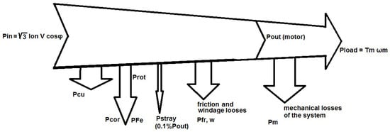
Figure 2.
Motor and elevator power loss flowchart.
4. Preliminary Design Stage of the PMSM and Experimental Validation
The optimal manufacturing configuration of a permanent magnet synchronous motor (PMSM) is a direct function of the application. In elevator applications, PMSMs are designed to serve the maximum load of the chamber and are characterized by their high mass and torque, multi-poles, and low rated speed. The main objective of this section focuses on the design of a PMSM by following parametric design rules, on the derivation of the results and operation of the machine using finite elements, and on the description of the experimental setup implemented within our research.
4.1. Description of the Experiment
The experimental setup using a PMSM for chamber lifting is shown in Figure 3. The structural parameters of the PMSM are shown in Table 1.

Figure 3.
View of the experimental setup. (1) Henning Acceleration Sensor QS3, (2) Ziehd Abegg Inverter for the driving system, (3) Interior Permanent Magnet (IPM), and (4) Power Quality Analyzer Hioki PW3390.

Table 1.
IPM design variables.
The value of parameters in Table 1 have been obtained after sensitivity analysis and the bold values are those obtained as optimal and applied in the simulation.
Using the experimental setup, various loading tests were carried out by applying a wide range of current phases to the machine. The instruments for measuring the elevator vibration and velocity, the motor output torque, input voltage and current waveforms were as follows: (1) Henning Acceleration Sensor QS3 of the manufacturer Henning GmbH & Co.KG from Germany in the city Halver, (2) Ziehd Abegg Inverter for the driving system of the manufacturer Ziehl-Abegg SE from Germany in the city Künzelsau, (3) Sicor Interior Permanent Magnet (IPM) of the manufacturer Sicor S.p.A. from Italy in the city Rovereto, and (4) Power Quality Analyzer Hioki PW3390 of the manufacturer Hioki E.E. Comporation from Japan in the city Ueda, Nagano. Also, the active power, frequency, and input and output power were measured by this experimental system to calculate the efficiency of the motor.
4.2. Design Methodology
An Interior Permanent Magnet (IPM) with surface magnets with 20 poles/60 slots in a star connection, a rated output power of 6.6 kW and nominal speed of 150 rpm was used. Figure 4 illustrates the basic design dimensions of the motor under study. The study of the torque at the rated operating condition and the maximum torque of the motor indicated that the outer diameter of the motor () could not be more than 35 cm to provide sufficient space for the windings and for thermal management. The airgap diameter was 1 mm to obtain better motor performance results with reduced losses. The axial length of the motor was sized as 220 mm as this ensured the required output power and efficient use of the material. The outer diameter of the rotor was chosen to achieve a balance between the magnetic flux and the mechanical stability of the rotor. In general, the main characteristics of these motor reduced mechanical losses in a vacuum load test and increased copper losses, which comprised most of the total motor losses. Its general geometric topology is illustrated in Figure 4a,b (2D and 3D respectively). A detailed view of the stator slot topology is depicted in Figure 5a, and the stator winding layout is shown in Figure 5b.
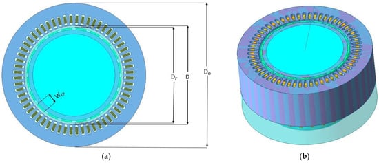
Figure 4.
Typical geometrical representation of the PMSM design: (a) 2D cross section of the whole motor and (b) 3D view of the topology under study.
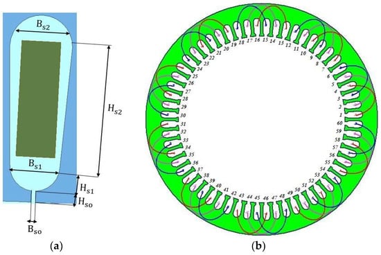
Figure 5.
Detailed view of the: (a) representation of the stator topology implemented and (b) stator winding connection with different color for each phase.
In order to select the appropriate winding connection, both series and parallel connections were investigated, and it was found that the series connection perfectly suited our application. At the same time, double layer winding was chosen to provide lower torque ripple and reduce iron losses, with the aim of reducing the harmonic content of the magnetomotive force. As for the materials, NdFe-35 was chosen for the permanent magnets along with M19-24G sheet metal, which is distinguished for its low losses in a stator core. The maximum value of the flux density in the airgap was 0.75 T, and given that the flux is lower with a higher number of poles, the stator and rotor magnetic material could be made thinner without a higher risk of saturation. The density of the stator winding was equal to 4 A/. This value can also guarantee a satisfactory thermal behavior of the motor by ensuring that during operation, no particularly high temperature develops near the gap, which would negatively affect the permanent magnets. The structural characteristics of the machine are shown in Table 1. The typical B-H curve for the magnetic iron laminate M19-24G is shown in Figure 6.
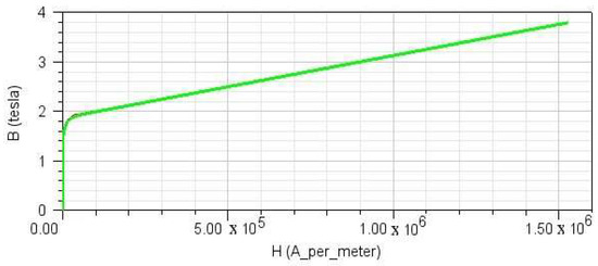
Figure 6.
Magnetization characteristics of magnetic iron laminate, M19-24G.
5. Two-Dimensional Finite Element Analysis
Utilizing the 2D finite element method, the performance of the machine was determined. Specialized software has the potential with fast and accurate calculations to solve time-dependent electromagnetic problems. Initially, the first step of the motor design was carried out, and the properties of the stator, rotor and magnets materials were assigned.
This PMSM was excited with pure sinusoidal currents with an rms value equal to 12.4 A. At its rated characteristics, it provides an average torque of 450 Nm at 150 rpm. At these operating conditions, the minimum () and maximum () torque values are equal to 447.19 and 460 Nm, respectively, as shown in Figure 7, with a torque ripple of 4.30%. The torque variations are extremely low, while the high inertia of the rotor contributes to the stability of its operation.
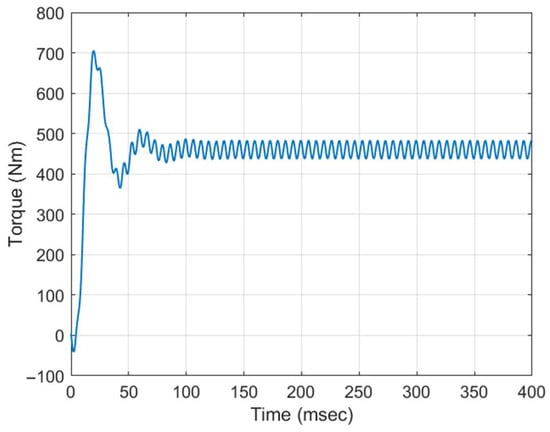
Figure 7.
PMSM torque variations versus time.
In general, the efficiency of the motor at 150 rpm is estimated at 88–90% (as shown in Figure 8), which is much better that that of other machines in which the frequency is particularly low ranging, with 80–85% efficiencies. Most of these losses are related to copper as they are the main reason why the efficiency is particularly low at low rpms. The core of the stator is mainly affected by the harmonic components of the stator field, as it moves synchronously with the fundamental component. The magnets exhibit bipolar losses and, due to the fact that they are located on the surface of the rotor, they are strongly stressed by the stator.
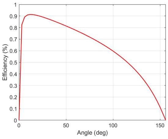
Figure 8.
Efficiency variation under an angle.
By changing the load by varying the current (Figure 9, Figure 10, Figure 11, Figure 12, Figure 13 and Figure 14) and the supply voltage in the machine windings, we were able to achieve a significant approximation with the experimental results using the 2D finite element method at steady-state, in which particular measurement deviations were found. Even when overload conditions remained at high levels, the PMSM shows a high efficiency and current, and in this example, we observed a higher Imax mainly during the start of the elevator.
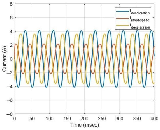
Figure 9.
Current waveforms for 0 kg during the ascent.
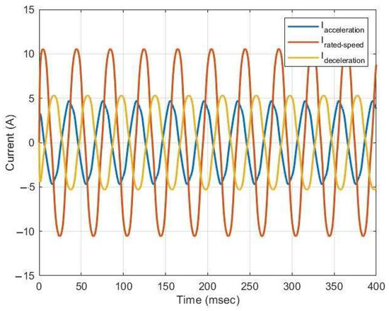
Figure 10.
Current waveforms for 0 kg during the descent.
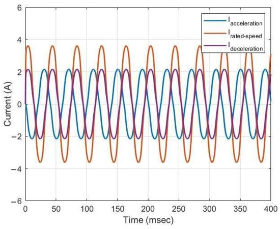
Figure 11.
Current waveforms for 315 kg during the ascent.
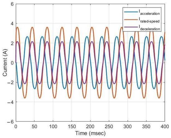
Figure 12.
Current waveforms for 315 kg during the descent.
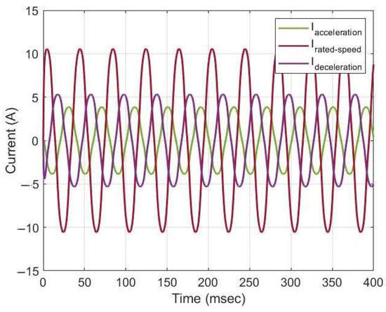
Figure 13.
Current waveforms for 630 kg during the ascent.
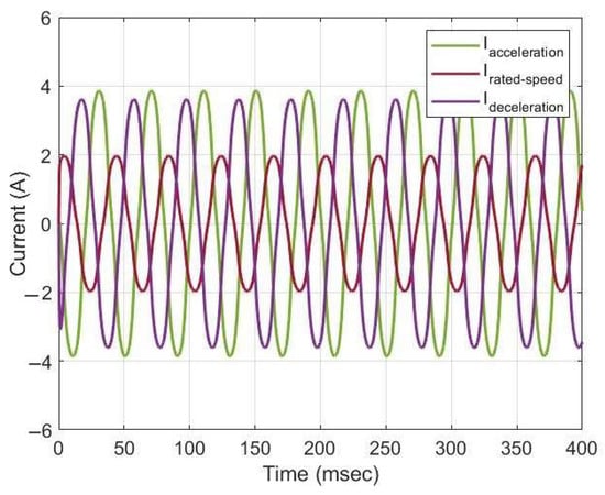
Figure 14.
Current waveforms for 630 kg during the descent.
The magnetic field (shown in Figure 15) inside the machine comes exclusively from the permanent magnets of the rotor. In this state, the magnetic field is almost evenly distributed throughout the motor, as there is no additional field resulting from stator currents to affect or distort it. The stator currents create their own magnetic fields, which interact with the magnetic field, causing torque. The field inside the machine has its highest values at the stator teeth just above the magnets, since that is where most of the magnetic flux is concentrated. Also, the magnetic circuit of the core is not saturated, since the field value does not exceed 1.8 T anywhere. This leaves room for overloading the magnetic circuit, as will be shown below.
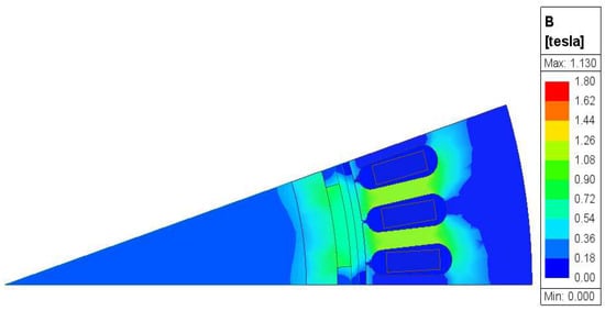
Figure 15.
Magnetic flux density distribution of the PMSM under nominal operating conditions (1/ part).
6. Application VVVF in Elevators
One of the main criteria for the design of energy efficient buildings is the energy class of the elevator, as several studies have shown the possibility of saving more than 60% of the energy by applying appropriate techniques [62]. The development of power electronics for driving geared PMSMs has led to significant energy savings, with variable voltage variable frequency (VVVF) the most typical [63]. This technique is quite useful, as it offers high energy savings proportional to the reduction in load torque, while the corresponding speed controllers regulate the speed of the system in general [64].
Furthermore, additional factors to be investigated are the load that the lift is required to serve during its operation and the daily number of calls. These parameters were investigated using real experimental data. The results showed that by using both VVVF [65] and regenerative braking [22], the higher the number of calls, the higher the percentage of energy savings. With the use of regenerative braking, more energy savings were observed with a 20–25% higher efficiency compared to without regenerative braking, and in some cases the savings can reach even higher [66]. The application of various control techniques in driving the system contributes to the fault tolerance of the motor, which is particularly important both for increasing its lifetime and for the safe movement of the passengers, as it ensures robust survival in case of any problems [47].
6.1. Modeling of the System
The evolution of power electronics enables their use in elevator applications, more specifically, to control the speed and current by with a suitable inverter in the system. The VVVF provides capabilities such as energy savings, reduced power consumption and regenerative braking [67].
An AC-DC-AC inverter in which speed control is a function of frequency variation achieves the best possible accelerating and decelerating chamber motion while maintaining maximum torque [68]. In Figure 16, we can observe the general regenerative braking and VVVF driving topology, which consists of the rectifier that converts the three-phase AC mains current to direct current (AC/DC), the converter that converts the DC voltage to variable frequency and amplitude-controlled AC voltage, and the control unit that appropriately modulates the output voltage in pulse form [69].
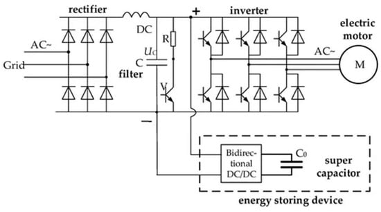
Figure 16.
General topology of regenerative braking and VVVF inverter.
The operation of the VVVF control is based on the proper adjustment of the elevator speed curve during both the ascending and descending movement of the chamber. Figure 17a,b shows the experimental ascent and descent curves for the cases of an empty load (0 kg), half load (315 kg) and full load (630 kg). The user has the possibility to program the memory of the inverter with the desired curve in order to achieve movement optimization of the elevator chamber from one floor to another. The chamber movement configuration largely determines the percentage of energy savings that will be achieved. A typical movement definition includes three operational stages, as the elevator starts by performing an accelerated movement, then its speed is stabilized for the majority of its movement and finally it performs a decelerated movement in order to stop smoothly. Using the velocity curve data for the entire period of motion, we found that the elevator has a maximum constant speed of 1 m/s. Similarly, we can determine the acceleration variation characteristics that correspond to a 0.75 m/ mean acceleration and 0.75 m/ while the elevator is undergoing an abrupt and time-delayed decelerating motion, as observed from the measured acceleration motion curve in Figure 18a,b.
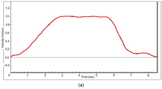
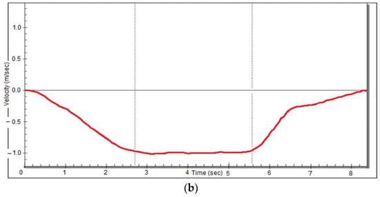
Figure 17.
Experimental curve velocity of the (a) ascending movement of the elevator with VVVF inverter and (b) descending movement of the elevator with VVVF inverter.
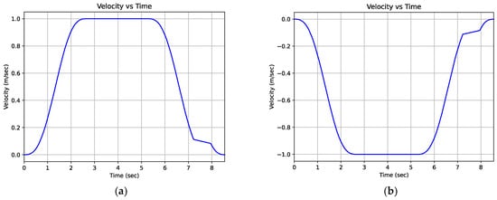
Figure 18.
Simulated speed-time curves of the elevator during (a) ascending chamber movement and (b) descending chamber movement.
The desired curve entered by the user in the central control unit of the inverter is compared with the actual speed of the elevator. By means of suitable speed controllers, the speed and the electrical frequency of the motor is controlled in order to be able to adjust the actual speed to the desired value. A comparison of the data is characterized by the accuracy with which the operation is carried out at regular intervals in order to observe a noticeable improvement in the operating speed throughout the entire travel.
6.2. Energy Savings with the VVVF Control Technique
The driving of electric motors through a suitable VVVF inverter is intended to eliminate disadvantages, such as variations in efficiency and reductions in the power factor, during the extreme case of operation under vacuum load. In addition, other factors that affect the efficiency of the elevator motor include the following: the lamination of the starter, the improvement of the power factor, the regulation of the generated power and the consumption of the motor according to the load it serves at any given time.
Frequent abrupt changes lead to jolts, greater stress on mechanical parts and faster wear. The driving system therefore plays multiple roles, contributing to smooth movement; the regulation of machine characteristics, especially during transient operation; energy savings; and in sophisticated systems, even contributing to fault diagnosis and fault-tolerant engine operation [67].
Energy savings with VVVF control is based on the development of a mathematical model of the electric motor, which is the main element of the drive system. The voltage and electromagnetic impetus are calculated as follows:
where J is the constant of the inertia of the rotor and load (kg), is the angular rotational speed of the motor (rad/s), b is the friction losses (Nm/rad/s), and is the component of the load thrust.
The consumption of the machine is proportional to the mechanical work it must perform at any given time. In electromechanical elevators with a nominal velocity of more or less 1 m/s, the role of the speed controllers of the VVVF inverter is important. For the vertical transfer of a given load F with spatial displacement S, the generated work W is equal to the following:
W = FS
The average power is calculated as the work in the time interval dt:
From the characteristic curves between two stops of the lift, it follows that the distance is given by the area of the movement curve. For there to be an energy savings of the transport of a constant load, the area of the curve must be reduced. Using the experimental ascent and descent curves of Figure 17a,b and assuming that the curve has the shape of an ideal table, we can calculate the space S between two stops of the elevator (m):
where S is the area of the velocity-time curve, T is the total time of the course between two stops (s), is the maximum constant velocity (m/s), = / is the acceleration time, = / is the deceleration time, is the acceleration of the lift (m/), and is the deceleration of the lift (m/).
Substituting the relationships for and in Equation (33) gives the following:
Especially in drive systems and elevator systems in which the load for each movement is constant, the energy consumption depends on the distance and the mode of movement.
The total energy consumed by the elevator along the distance S between two stations with a constant load is calculated as follows:
Thus, if a constant travel time is assumed based on Equation (34), the smaller the acceleration and deceleration, the smoother the acceleration and deceleration at the start and stop, respectively, the more the area of the curve is reduced, which reduces the energy consumption. The achievement of the maximum movement of the chamber is based on the average speed of the elevator :
where is the average service speed elevator (m/s) of the movement S, and is the total time it takes to the open and close the door when the elevator is stopped (s).
6.3. Elevator Duty Cycle Analysis
Regarding the operating states of the elevator depending on its load, the only variable that is adjusted to keep the speed of the lift constant is the torque of the motor. The following diagrams depict the simulated curves of the linear velocity (shown in Figure 18a,b), the acceleration during the ascent and descent movement of the chamber (Figure 19a,b), and the torque of the electric motor for three different values of payload (Figure 20a,b). Using Table 2, we calculated the value of the basic mechanical parameters.
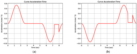
Figure 19.
Simulated acceleration-time curves of the elevator during (a) ascending chamber movement and (b) descending chamber movement.
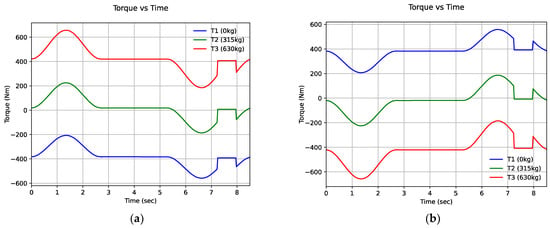
Figure 20.
Simulated mechanical torque-time curves of the elevator during (a) ascending chamber movement and (b) descending chamber movement.

Table 2.
Mechanical parameter variables.
From the analysis of the motion curves of the elevator—not only in the steady-state, but also in the dynamic transient state—important conclusions can be drawn for the correct design of the motor to serve the mechanical load, and also for the selection of a suitable power and the possibilities for energy saving.
The energy consumption during motion is calculated as power time, (kWh). Therefore, the energy consumed corresponds to the area of the power curve P × t, but is proportional to the speed curve because it is also dependent on the load carried at any given time. Since the steady-state movement is at a constant speed, the only possibility of limiting the area of the curve and therefore the energy savings is given during transition periods. Thus, steep accelerations and decelerations lead to an increase in energy consumption, but also produce a sudden jerk in passenger movement.
The electric drive includes drive and control settings for the electric motors (position and speed) so that they are constantly adapting to the requirements of the moving system (load). The correct design of a drive system requires a good knowledge of the steady-state and dynamic behavior of all the components, as it is by their action and interaction that the desired results are achieved. The smoother the acceleration and deceleration are, especially of the second and third derivatives known as jerking, the greater the energy savings are, and at the same time, the greater the sense of comfort of the passengers. But this results in an overall increase in journey time and service time for the passengers. The speed curve and its slope, which are the acceleration and deceleration rate values, are programmed in the inverter of the lift system and must take into account the combined energy savings, comfort of travel and the desired journey time for optimal passenger service. For safety reasons, there is a speed regulator that activates the gripping device and stops the elevator if the chamber exceeds its speed limit by a certain percentage, which is an additional advantage of mechanical lifts.
The mechanical torque of the load depends not only on the moving weight, but also on the acceleration and the effect of gravity. The maximum torque load moment occurs during the transition period when the acceleration of the ascent is maximum. During ascending and descending movements in the travel cycle, the load torque is opposite to the motor torque, thus enabling the application of regenerative mechanisms for maximum energy savings.
The test cases were an ascent with an empty load (0 kg) and a descent with a full load (630 kg) in the chamber. But regenerative mechanism can be applied in two additional cases of locomotion through regenerative braking, as a result of the inversion of the mechanical torque with respect to the electromagnetic torque of the motor. In the cases of deceleration during ascent as well as acceleration during descent at half the rated speed (load 315 kg), based on Figure 21a,b we observe there is no negative power. At any given moment in time, power is the product of torque times speed. Thus, positive power is considered to be the power when speed and torque are in the same direction, while negative power is obtained when speed is in the opposite direction of the torque.
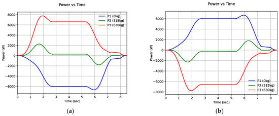
Figure 21.
Simulated motor power-time curve of the elevator during (a) ascending chamber movement and (b) descending chamber movement.
An elevator is a driving system that, when carrying a constant load at a constant speed during its movement, is in a steady-state. The selection of the rated power, P, must take into account extreme loading conditions and the speed of movement. For lifting a constant load, the motor power is proportional to the travel speed V. This can be seen from the shape of the power curve, which has exactly the same characteristics as the speed curve.
The exact calculation of the weight of the counterweight plays a very important role in the stress of the machine and in the energy savings during a multi-trip cycle. The power and torque curves show that even a small deviation in the weight of the anti-vibration weight of half the rated load can lead to overloading and overheating of the electric motor, either on the ascent, if it is of a lower weight, or during the descent, if it is heavier, with a corresponding increase in current consumption.
The motor driving system used with a VVVF inverter can provide an appropriate solution, and adjust the speed and acceleration by varying the supply voltage and frequency in order to reduce the effect of the electric motor stress, especially during frequent transient start periods. In one of the cycles of the elevator (ground floor to seventh floor) it became apparent that the motor operates at a constant torque value for about 70% of its running time. By observing the torque and power curves, we found that after 2.7 s the motor is operating in steady-state (400 Nm and 150 rpm). In addition, Figure 22a,b shows that the transient mode lasts only 2.7 s for both ascending and descending motion. According to the probability density diagram in Figure 23, at the torque-speed level, the probability of the electric motor operating optimally at certain points can be evaluated.
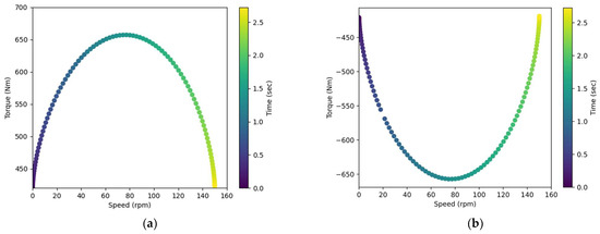
Figure 22.
Transitional start-up of the elevator during (a) ascending chamber movement and (b) descending chamber movement.
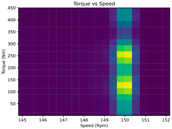
Figure 23.
Probability density torque-speed diagram (the yellow color indicates the max value).
7. Control Techniques for Driving a PMSM
The evolution of power electronics and the application of appropriate control techniques have yielded better results as far as driving PMSMs is concerned. Particularly in elevator applications, special research interest is given to speed and current controllers during motor operation. The interest is intense, as the development of very high currents and speeds can cause serious faults in both the motor windings and bearings. Fault-tolerant system design focuses on designing optimal controllers to ensure that the motor exhibits continuous uninterrupted operation even in the event of a single-phase short circuit [70,71].
In recent years, many advanced nonlinear control topologies have been developed to optimize the speed control of PMSM motors in various applications. These techniques range from the most traditional, such as scalar and vector control, to the most sophisticated ones, incorporating neural networks and fuzzy logic [72]. The most typical PMSM control technique in elevators is field-oriented control (FOC), even though it is considered by many to be the most complex process due to the variability of operational characteristics of the motion system. Therefore, a solution using several construction controllers is preferred in order to avoid de-synchronization and to have the possibility of self-regulation by using sophisticated algorithms. These are the PI and PID controllers that can control the elevator speed and adjust the motor power to reduce the speed error, respectively.
The integration of microprocessors led to the development of complex systems that execute operating programs with an increased degree of control precision, providing improved reliability and flexibility. Rotation control of a PMSM can be accomplished in several ways. We mentioned the control of the active rate of the stator supply voltage, the connection of an external variable resistor to the rotor windings (for ring machines), varying the number of poles, and varying the frequency and supply voltage of the stator. The latter mode offers the most advantages.
The inner current loop is one of the key components of FOC and plays an important role in controlling the speed and torque of electric motors. Its mode of operation is based on controlling the motor current along d-q axis in order to investigate the field orientation and the motor magnetization. Both PI and PID controllers are used in order to adjust the current in the d and q axes and generate the required reference voltages for the inverters [73]. Figure 24 below shows the block diagram of the field-oriented control (FOC), in which we can see that the internal current loop is responsible for the accuracy and stability while controlling the speed and torque of the motor (* indicates the reference values).
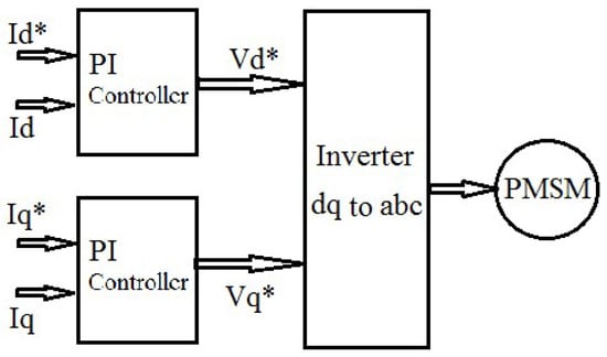
Figure 24.
Block diagram of field-oriented control (FOC).
7.1. Current Consumption PMSM
We used an experimental setup to determine the operating characteristics of the PMSM, as shown in Table 3, supplied with an inverter and using vector control technique. Based on the electrical and mechanical parameters of the motor, we determined that it is multi-pole motor, with a low mechanical speed and high nominal voltage. In addition, we observed a maximum torque in order for the motor to be able to serve the rated load of the chamber, and a maximum current value related to winding safety issues due to the transient during the acceleration of the elevator. The methodology was adapted to a smooth speed variation strategy in order to calculate the current consumption as a function of the load and the motion, as shown in Figure 25a,b, Figure 26a,b, Figure 27a,b, Figure 28a,b, Figure 29a,b and Figure 30a,b.

Table 3.
Technical characteristics of the PMSM.
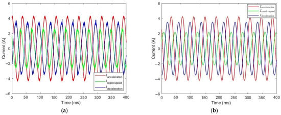
Figure 25.
Current consumption during the ascent of the elevator with 0 kg: (a) simulation curves and (b) experimental curves.
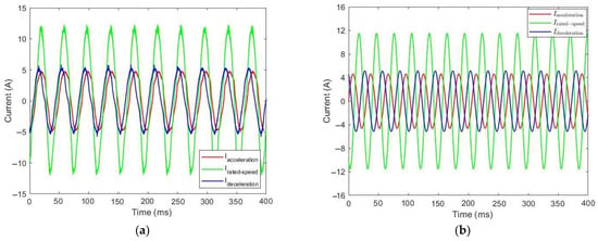
Figure 26.
Current consumption during the descent of the elevator with 0 kg: (a) simulation curves and (b) experimental curves.
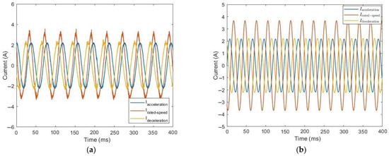
Figure 27.
Current consumption during the ascent of the elevator with 315 kg: (a) simulation curves and (b) experimental curves.
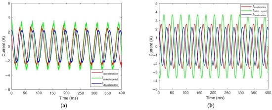
Figure 28.
Current consumption during the descent of the elevator with 315 kg: (a) simulation curves and (b) experimental curves.
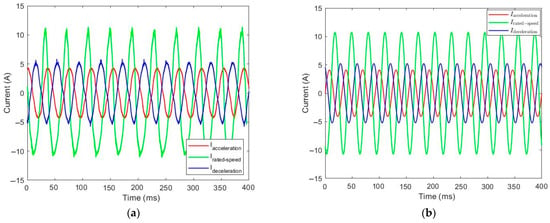
Figure 29.
Current consumption during the descent of the elevator with 630 kg: (a) simulation curves and (b) experimental curves.
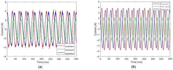
Figure 30.
Current consumption during the descent of the elevator with 630 kg: (a) simulation curves and (b) experimental curves.
In order to study the operating characteristics of the elevator using PMSM and a VVVF inverter, the electrical and mechanical parameters (shown in Table 3) of the motor are necessary to confirm the dynamic control model with the experimental data. Since = we found that with the motor has a cylindrical rotor, as it does not exhibit any priming, since regardless of the field angle with respect to the rotor, the magnetic circuit has the same magnetic resistance.
Both the simulated and experimental time variations of the stator current windings in the steady-state during the motions demonstrate that the current consumption depends significantly on the counterweight and load. In the case of the empty load, the counterweight is heavier than the empty chamber, so during the descent, the PMSM has to lift the counterweight because it has a higher load, using more power and therefore a higher current consumption. Also, we found that the simulated current control curves are consistent with the experimental curves in the steady-state.
During the rise of the empty load, the counterweight (through which the suspension of the chamber is carried out) is lowered, and with the help of gravity, the electric motor has a lower load, and less power and current. In Figure 25a, during the steady-state chamber motion, we observe a strong transient effect and the motor operating at its nominal characteristics. The transient effect is observed to reach 17 A, which is very close to the 19 A we know from the electrical parameters of the motor. During the ascent period, the velocity is positive, and the torque is negative. So, in the rise (except for the short initial and final interval) the motor is drawing the load at zero speed and absorbing power, and the motor acts as a generator, providing additional energy savings potential. In these cases, an inverter with dual power flow capacity is needed, and the energy savings reaches 30%. Most of the negative power will be recovered to charge the battery. However, many elevator manufacturers, due to the increased cost of the battery, choose to immediately return part of the energy to the power grid, even when using a photovoltaic panel to save energy, mainly in the event of the elevator being stationary.
As for the half load, the weight of the chamber is about the same as the weight of the counterweight, so on either ascent or descent, the electric motor has about the same load and the same consumption in both directions of motion. With approximately half the rated load (315 kg) during the ascent and descent of the chamber, we found that the power during acceleration and deceleration is the lowest possible. This result demonstrates that, compared to the empty load, more energy is saved, as the power only covers the mechanical friction losses. Reducing mechanical friction losses further improves the efficiency of the system.
Similarly, in the full load (630 kg) the chamber has a higher weight than the counterweight, and during the ascent the electric motor has a higher load, so more power and consumption is required, while during the descent of the full load, due to gravity, the electric motor has a lower load, using less power with lower consumption.
Thus, it becomes obvious that the correct calculation of the weight of the counterweight plays an important role in energy consumption, especially when the elevator serves half of its rated load, which is the most common case in lift systems. A counterweight that is heavier leads to increased power consumption during car descent, while a counterweight that is lighter similarly leads to increased power consumption during car ascent in the case of a half load. This problem could be minimized by implementing an energy recovery system during reverse motion. In this manner, the energy efficiency potential of the building is improved mainly during the time when the lift is a standby mode. Due to its many individual subsystems (safety devices, sensors, etc.), the elevator consumes energy even in the standstill phase, so this energy can be used for these operational situations.
7.2. Different Speed Control Techniques for Driving PMSM
The programming of the chamber velocity in the inverter depends on the motor speed setting. One of the main advantages of the gearless PMSM is the absence of the gearbox; therefore, the speed control depends on the proper specification of the controllers. The aim is to specify the controllers appropriately in order to accomplish smooth motor speed and accommodate smoother movement of the chamber by reducing the vibrations that create additional harmonic losses in the system.
In addition, the appropriate adjustment of the speed of the electrical motor also determines the smooth transition of the chamber, as no particular accelerations and over-accelerations are observed during the operation. Figure 31 illustrates the control of the nominal speed motor (150 rpm for 8 s) by configuring three different types of PI and PID controllers, which, by comparing with the experimental data, we can use to establish the type of controller that is suitable for use in the elevator system.
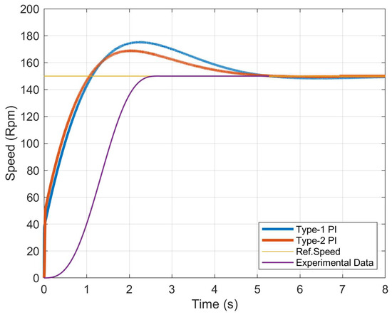
Figure 31.
Motor speed using PI controllers.
The main characteristics of both types of PI controllers is their use to achieve optimal control of the speed of the drive system. The Type–1 controller is characterized by its adaptability to different loading conditions, stability and simplicity in its operation. On the other hand, Type–2 is an advanced version of the basic PI controller, and demonstrates an increased response, advanced tuning of the maximum chamber speed and reduced errors. PI-Type 1 and PI-Type 2 controllers differ in both gain and structure. First, as far as gain is concerned PI-Type 1 has a fixed analog gain and a fixed integral gain. PI–Type 2 can have a variable gain, either in its analog or integral component. This means that there may be some adjustment of the gains according to system requirements or error signals. In addition, the manufacturing structure of PI–Type 1 is used because it is considered to be simpler and includes the two components (the analog and the integral components), compared to PI–Type 2 in which the structure may be more complex. In PI-Type 2 the control signal can be passed through an optimization Q(s) block, which may include filters or dynamic adjustments (Figure 32). The basic form of the controller is as follows:
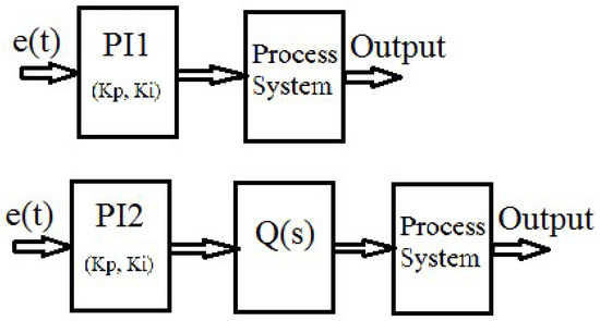
Figure 32.
Block diagram of PI–Type 1 and PI–Type 2 controllers.
The motion curve of the elevator with a constant load plays a very important role in energy savings, and it can be seen from the energy consumption equation that it is mainly a transient effect (acceleration and deceleration rate) that can be adjusted to achieve the optimal motion curve for both passenger comfort and lower energy consumption.
The purpose of the controllers is therefore to follow the programmed speed curve in the elevator so that the area of the transient is as small as possible. From the Type–1 PI diagram, it can be seen that oscillations and an abrupt transition cause a larger increase in energy consumption, while a smooth transition and variations in the acceleration rate, especially the second derivative of the acceleration (), reduce the corresponding area of the motion curve and lead to greater energy savings without reducing the desired and predetermined path transition time (PID–Type 2). Table 4 and Table 5 illustrate the main design parameters of the two types of controllers (PI Type 1–Type 2).

Table 4.
Parameters of PI controllers.

Table 5.
Performance of the examined PI controllers (time–response characteristics).
The selection of the appropriate type of controller for smooth driving and the reduction of intense transients during starts and stops is of primary importance, especially in high traffic elevators with a high number of calls per hour in the peak period. Also, we observed from the curves that PI-2 Type is closer to the experimental results, since although the second curve shows more oscillations, which is a result of the over-acceleration of the elevator, it takes a few more seconds to reach the nominal speed of the motor, but it starts in the same time interval as the experimental data to stabilize the speed of the motor. The smaller lift in the transition stage and the smaller fluctuation leads to greater current savings and also smoother acceleration and overshooting.
Adjustment of overshoot in a speed controller can be achieved through proper configuration of the controller parameters. Typically, overshoot occurs when the system speed exceeds the desired value before converging to a stable value. The addition of the D parameter reduces overshoot while improving damping. For a PID controller, the output signal u(t) is defined as follows:
where u(t) is the output signal of the controller, Kp is the ratio of the proportional gain, Ki is the ratio of the integral gain, Kd is the ratio of the derivative gain and e(t) is the error.
Similarly, the PID controller widely used in industrial applications is preferred for its simple operation under many different operating conditions, but also for its advantages, including short rise time, minimal overshoot and zero permanent error. As can be seen from the curves in Figure 33, when the acceleration slope is steeper, we observe a reduction in overshoot in both the PID-Type 1 and 2 curve, with greater energy savings potential.
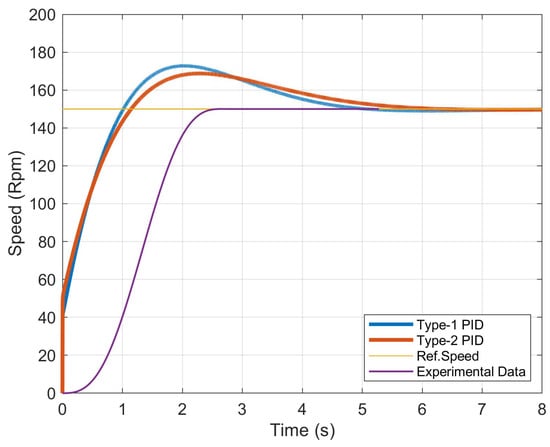
Figure 33.
Motor speed using PID controllers.
Better adaptation to a smooth change in acceleration reduces the superelevation without causing an increase in travel time and leads to greater system stability. Differential control also increases damping, reduces the transient effect and leads to greater energy savings and smoother motion (Type-1 PID). Table 6 and Table 7 illustrate the main design parameters of the two types of controllers (PID Type 1–Type 2). A comparison of Table 5 and Table 7 demonstrates that although both controllers have the same settling time, the Type-2 PID controller shows less overshoot and therefore smoother elevator acceleration during startup. The experimental motor speed curves are derived from the actual operating curves of the elevator in Figure 17a,b.

Table 6.
Parameters of PID controller.

Table 7.
Performance of the examined PID controllers (time–response characteristics).
8. Discussion
The current research reveals several outstanding needs that lend themselves to further investigation and analysis:
- Thermal and structure analysis of the selected geometry in order to understand if there are potential thermal issues throughout the operating cycles, and especially during overloads;
- Manufacturing and geometric configuration of a multiphase motor with high efficiency fault tolerance and low losses in elevator systems;
- Use of an inverter capable of maintaining motor operation in any possible fault that may occur;
- An examination of alternative winding configurations, such as concentrated non-overlapping winding (which may reduce copper losses), and compared with the results of the current investigation;
- Comparative investigation of other control techniques in order to study speed and current control;
- Application of geometric machine optimization methods, such as using various genetic algorithms and neural networks (NN);
- Comparative energy savings study using regenerative braking, because in high-speed elevators, a back-to-back inverter voltage source is used, as an elevator driven by an electric motor requires bidirectional control of the power flow for motor operation and power generation, which occurs repeatedly during acceleration and deceleration operations;
- Application of a filter to reduce the harmonic losses of the motor resulting from the use of the inverter.
9. Conclusions
The design of the PMSM as well as the drive system are the main points of this study on elevator traction. The importance and continuous development of electric elevators has established them as one of the most important means of transportation. The main conclusions drawn from this research highlight the use of PMSM electric motors in elevator technology due to their many effective advantages, their appropriate construction configuration, the energy saving potential of the drive system and the use of various controllers for the best possible elevator drive.
The main purpose of this research is optimizing the design of a PMSM, which is the basic transmission option in electromechanical elevators. Experimental and simulated data indicate that the efficiency of this machine during the duty cycle is in the range of 80%, while its rated operation is 88%, a significantly increased rate compared to hydraulic mechanisms, which show an average efficiency of 60%. This underlines the superiority of the mechanical lift. Thus, the analysis of the requirements in the application of mechanical lifts formed the basis for the targeted design of the motor.
The design of the drive system must take into account the specific requirements of an elevator. The nominal load is calculated on the basis of the dimensions of the car and the number of persons at a ratio of 75 kg per person. Correct calculations of the counterweight reduce the working force and the power requirement of the motor. The motor dimensions should be limited for installation within the manhole in systems without an engine room. The chamber speed for urban buildings cannot exceed 1 m/s, and therefore a motor with high torque and low speed is required to avoid a high gear ratio. Safety and a smooth operation, as well as smoothness in movement, are some of the requirements for robust designs to avoid malfunction, reduce maintenance costs, and achieve a long service life, but also appropriate controls must be used to limit acceleration and deceleration, resulting in satisfactory service speeds at peak times and economical operation during the cycles of ascending and descending movements.
In addition, the design configuration of the curvature of the magnet, in combination with its width and the manner in which it is magnetized, is a critical factor in determining the harmonic content of the field. This phenomenon was directly affected by significant parameters, such as the torque ripple and cogging torque, both in performance and in its behavior in higher harmonics. The surface magnet is an optimal choice compared to the alternative geometries considered in gearless induction motor.
As far as the investigation of the energy efficiency of the system is concerned, both simulated results and experimental measurements with different loads show significant energy savings by using VVVF technology. It is worth noting that a significant percentage of savings depends on the elevator loading conditions, the active power as well as the number of calls. Furthermore, based on the curves, no particular deviations were observed under an empty load. In contrast, higher energy savings were found in the half-load case compared to the full load case due to the active lifting force. The choice of the counterweight is critical, as the lower its weight was, the lower the energy consumption was under empty load conditions, but the consumption was higher at full chamber loads.
In order to achieve the best possible results in terms of system efficiency, it is necessary to adjust the motor speed appropriately. The field-oriented control (FOC) technique showed satisfactory responses by the controller in the tests implemented with load variations, indicating that the empirical fit of the PI controllers may provide improved performance compared to the theoretical one. The speed controller of the PMSM has a direct relationship with the control of the elevator velocity and its programming of the inverter. Moreover, the current waveforms highlight a convergence of the result with respect to the experimental data, while the transient appearance at start-up did not show a particular overshoot, as it converged with the maximum current of the electric motor, depending on the load.
Our study was based on two different types of PI and PID controllers, as well as on a collection of experimental data from the device. The results indicated that for our application, the best controller proved to be the Type-1 PID and Type-2 PID, as they were closer to the experimental results, and although it seems that the oscillations and abrupt transition caused a larger spike in energy consumption, the area of the curve was reduced, leading to higher energy savings. Similarly, a larger overshoot and hence higher power consumption was observed in the Type-2 PI as opposed to Type-1 PID, which showed better results in the system. Thus, we conclude that the appropriate type of controller for our application is the Type-2 PID.
Author Contributions
Conceptualization, V.I.V. and D.E.E.; methodology, V.I.V., D.E.E. and T.S.K.; software, V.I.V.; validation, V.I.V., D.E.E. and T.S.K.; formal analysis, V.I.V.; investigation, V.I.V., D.E.E. and T.S.K.; data curation, V.I.V. and T.S.K.; writing—original draft preparation, V.I.V.; writing—review and editing, V.I.V. and D.E.E.; visualization, V.I.V., D.E.E. and T.S.K.; supervision, V.I.V. All authors have read and agreed to the published version of the manuscript.
Funding
This research received no external funding.
Data Availability Statement
Data is contained within the article.
Conflicts of Interest
The authors declare no conflicts of interest.
References
- Guo, Y.; Ba, X.; Liu, L.; Lu, H.; Lei, G.; Yin, W.; Zhu, J. A Review of Electric Motors with Soft Magnetic Composite Cores for Electric Drives. Energies 2023, 16, 2053. [Google Scholar] [CrossRef]
- Zhang, B.; Song, Z.; Liu, S.; Huang, R.; Liu, C. Overview of Integrated Electric Motor Drives: Opportunities and Challenges. Energies 2022, 15, 8299. [Google Scholar] [CrossRef]
- Umland, N.; Winkler, K.; Inkermann, D. Multidisciplinary Design Automation of Electric Motors-Systematic Literature Review and Methodological Framework. Energies 2023, 16, 7070. [Google Scholar] [CrossRef]
- Hunt, J.D.; Nascimento, A.; Zakeri, B.; Jurasz, J.; Dabek, P.B.; Barbosa, P.S.F.; Brandao, R.; De Castro, N.J.; Filho, W.L.; Riahi, K. Lift Energy Storage Technology: A solution for decentralized urban energy storage. Energy 2022, 254, 124102. [Google Scholar] [CrossRef]
- Bakhtiarzadeh, H.; Polat, A.; Ergene, L.T. Design and analysis of a permanent magnet synchronous motor for elevator applications. In Proceedings of the International Conference on Optimization of Electrical and Electronic (OPTIM) & Intl Aegean Conference on Electrical Machines and Power Electronics (ACEMP), Brasov, Romania, 25–27 May 2017; pp. 293–298. [Google Scholar]
- Ang, J.H.; Yusup, Y.; Zaki, S.A.; Salehabadi, A.; Ahmad, M.I. Comprehensive Energy Consumption of Elevator Systems Based on Hybrid Approach of Measurements and Calculation in Low-and High-Rise Buildings of Tropical Climate towards Energy Efficiency. Sustainability 2022, 14, 4779. [Google Scholar] [CrossRef]
- Al-Sharif, L.; Tutunji, T.A.; Ragab, D.; Kayfi, R. Using Elevator system modelling and simulation for integrated learning in mechatronics engineering. In Proceedings of the International Workshop on Research and Education in Mechatronics (REM), El Gouna, Egypt, 9–11 September 2014. [Google Scholar]
- Chen, J.W.; Tran, T.N.T.; Tsai, M.F. Design on Phase Angle Control Strategy for Three-Phase-Current PMSM Elevator. In Proceedings of the 46th Annual Conference of the IEEE Industrial Electronics Society (IECON), Singapore, 18–21 October 2020; pp. 926–930. [Google Scholar]
- Wang, G.; Xu, J.; Li, T.; Zhang, G.; Zhan, H.; Ding, L.; Xu, D. Weight-Transducerlsess Starting Torque Compensation of Gearless Permanent-Magnet Traction Machine for Direct-Drive Elevators. IEEE Trans. Ind. Electr. 2014, 61, 4594–4604. [Google Scholar] [CrossRef]
- Stawinski, L.; Zakharov, V.; Kosucki, A.; Minav, T. Electromechanical Actuator-Based Solution for a Scissor Lift. Actuators 2023, 12, 394. [Google Scholar] [CrossRef]
- Ezzaldean, M.M.; Bakr, M.S. Control System for Experimental Model of Electric Elevator. J. Contr. Robot. Mechan. Syst. 2015, 1, 22–26. [Google Scholar]
- Bernard, P.; Deaconu, I.D.; Popescu, S.V.; Ghita, C.; Deaconu, A.S.; Chirila, A.I. PLC Controlled Elevator Drive System. In Proceedings of the International Symposium on Advanced Topics in Electrical Engineering (ATEE), Bucharest, Romania, 7–9 May 2015; pp. 166–169. [Google Scholar]
- Selek, M.; Terzioglu, H.; Kazan, F.A. The Design of Training Elevators for Effective Learning. In Proceedings of the International Conference on Information Science and Control Engineering, Shanghai, China, 24–26 April 2015; pp. 956–959. [Google Scholar]
- Knezevic, B.; Blabusa, B.; Marcetic, D. Design of Elevator Drive with Jerk Control. In Proceedings of the International Symposium on Power Electronics, Novi Sad, Servia, 26–28 October 2011; pp. 1–4. [Google Scholar]
- Blanusa, B.; Knezevic, B.; Erceg, B.; Lekic, O.; Mrsic, P. Elevator drives: Present trends and perspectives. In Proceedings of the International Conference on Electromechanical and Power Systems (SIELMEN), Iasi, Romania, 11–13 October 2017; pp. 001–009. [Google Scholar]
- Bakhtiarzadeh, H.; Polat, A.; Ergene, L.T. The analysis of different stator designs of a PMSM for elevator application. In Proceedings of the International Conference on Control Engineering & Information Technology (CEIT), Istanbul, Turkey, 25–27 October 2018. [Google Scholar]
- Avsar, Y.; Fenercioglu, A.; Soyaslan, M. Design Optimization of PM Synchronous Motor Used in Belt Drive Elevator Systems. In Proceedings of the International Conference on Computing, Power and Communication Technologies (GUCON), Kuala Lumpur, Malaysia, 24–26 September 2021; pp. 1–5. [Google Scholar]
- Fang, S.; Liu, H.; Wang, H.; Yang, H.; Lin, H. High Power Density Permanent Magnet Synchronous Motor With Lightweight Structure and High-Performance Soft Magnetic Alloy Core. In Proceedings of the IEEE International Conference on Applied Superconductively and Electromagnetic Devices (ASEMD), Tianjin, China, 15–18 April 2018; pp. 1–2. [Google Scholar]
- Wang, H.; Leng, J. Summary on development of permanent magnet synchronous motor. In Proceedings of the Chinese Control And Decision Conference (CCDC), Shenyang, China, 9–11 June 2018; pp. 689–693. [Google Scholar]
- Rafaq, M.S.; Jung, J.W. A Comprehensive Review of State-of-the-Art Parameter Estimation Techniques for Permanent Magnet Synchronous Motors in Wide Speed Range. IEEE Trans. Ind. Inform. 2020, 16, 4747–4758. [Google Scholar] [CrossRef]
- Avsar, Y.; Fenercioglu, A.; Soyaslan, M. Design Optimization of PM Synchronous Motor: Rail Mounted Belt Drive Elevator Systems. IEEE Trans. Ind. Appl. 2024, 60, 301–311. [Google Scholar] [CrossRef]
- Erica, D.; Godec, D.; Kutija, M.; Pravica, L.; Pavlic, I. Analysis of Regenerative Cycles and Energy Efficiency of Regenerative Elevators. In Proceedings of the International on Electrical Drives & Power Electronics (EDPE), Dubrovnik, Croatia, 22–24 September 2021; pp. 212–219. [Google Scholar]
- Sawna, J.; Seferian, V.; Khatounian, F.; Monmasson, E.; Ghosn, R. An improved anti-rollback control algorithm for gearless traction motor in elevator applications. Mechatronics 2021, 79, 102659. [Google Scholar] [CrossRef]
- Anand, R.; Mahesh, M. Analysis of elevator drives energy consumptions with permanent magnet machines. In Proceedings of the IEEE Smart Energy Grid Engineering (SEGE), Oshawa, ON, Canada, 21–24 September 2016; pp. 186–190. [Google Scholar]
- Yetis, H.; Mese, E.; Bayikli, M. Design and Comparison of Ferrite Based IPM and NdFeB Based SPM Synchronous Motors for Gearless Elevator Systems. In Proceedings of the International Conference on Electrical Machines (ICEM), Alexandroupoli, Greece, 3–6 September 2018; pp. 635–641. [Google Scholar]
- Vagati, A.; Boazzo, B.; Guglielmi, P.; Pellegrino, G. Design of Ferrite-Assisted Synchronous Reluctance Machines Robust toward Demagnetization. IEEE Trans. Ind. Appl. 2014, 50, 1768–1779. [Google Scholar] [CrossRef]
- Sim, J.H.; Ahn, D.G.; Kim, D.K.; Son, D.K.; Kim, S.; Hong, J.P.; Lee, T.H. Multiphysics Design of Triple 3-Phase PMSM for Ultra-High Speed Elevator Applications. In Proceedings of the International Conference on Electrical Machines (ICEM), Alexandroupoli, Greece, 3–6 September 2018; pp. 284–290. [Google Scholar]
- Petrov, I.; Pyrhonen, J. Performance of Low-Cost Permanent Magnet Material in PM Synchronous Machines. IEEE Trans. Ind. Electron. 2013, 60, 2131–2138. [Google Scholar] [CrossRef]
- Vlachou, V.I.; Sakkas, G.K.; Xintaropoulos, F.P.; Pechlivanidou, M.S.C.; Kefalas, T.D.; Tsili, M.A.; Kladas, A.G. Overview on Permanent Magnet Motor Trends and Developments. Energies 2024, 17, 538. [Google Scholar] [CrossRef]
- Laskaris, K.I.; Kladas, A.G. Internal Permanent Magnet Motor Design for Electric Vehicle Drive. IEEE Trans. Ind. Electron. 2009, 57, 138–145. [Google Scholar] [CrossRef]
- Mohammed, J.A.; Shuraiji, A.L. Modelling of DC Elevator Motor Drive for Mid-rise Building. Eng. Technol. J. 2013, 31, 2320–2342. [Google Scholar] [CrossRef]
- Tukia, T.; Uimonen, S.; Siikonen, M.L.; Hakala, H.; Lehtonen, M. A study for improving the energy efficiency of lifts with adjustable counterweight. Build. Serv. Eng. Res. Technol. 2017, 38, 421–435. [Google Scholar] [CrossRef]
- Karakatsanis, T.S. Modeling of elevators as Driving systems. In Proceedings of the International Association of Elevator Engineering (IAEE), Thessaloniki, Greece, 11–13 June 2008. [Google Scholar]
- Yetis, H.; Boztepeli, H.; Yasa, Y.; Mese, E. Comparative design of direct drive PM synchronous motors in gearless elevator systems. In Proceedings of the International Conference on Electric Power and Energy Conversion Systems, Istanbul, Turkey, 2–4 October 2013. [Google Scholar]
- Ford, P.J.; Amiri, E.; Mendrela, E. Electric elevator drive with position control. Electr. Eng. 2016, 98, 309–319. [Google Scholar] [CrossRef][Green Version]
- Yetis, H.; Mese, E. Design of IPM Synchronous Motor for Gearless Elevator Applications. In Proceedings of the International Conference on Engineering Technology an Innovation (ICETI), Sarajevo, Bosnia and Herzegovina, 23–26 March 2017; pp. 1–6. [Google Scholar]
- Kannojia, P.; Chinmaya, K.A. Comparative Review and Finite Element Analysis of Energy Efficient Motors. In Proceedings of the International Conference on Power Electronics and Energy (ICPEE), Bhubaneswar, India, 3–5 January 2023. [Google Scholar]
- Yan, B.; Li, X.; Wang, X.; Yang, Y.; Chen, D. An Improved 2-D Subdomain Method toward Electromagnetic-Performance Analysis of Line-Start Permanent Magnet Synchronous Motor. IEEE Trans. Transp. Electr. 2023, 57, 4339–4351. [Google Scholar] [CrossRef]
- Chadebec, O.; Bui, V.P.; Granjon, P.; Rouve, L.L.; Bihan, N.L.; Coulomb, J.L. Rotor fault detection of electrical machines by low frequency magnetic stray field analysis. In Proceedings of the International Symposium on Diagnosis for Electric Machines, Power Electronics and Drives, Vienna, Austria, 7–9 September 2005. [Google Scholar]
- Lehikoinen, A.; Arkkio, A.; Belahcen, A. Reduced Basis Finite Element Modeling of Electrical Machines with Multiconductor Windings. IEEE Trans. Ind. Appl. 2017, 53, 4252–4259. [Google Scholar] [CrossRef]
- Pechlivanidou, M.S.C.; Chasiotis, I.D.; Karnavas, Y.L. A comparative study on 2D and 3D magnetic field analysis of permanent magnet synchronous motor using FEM simulations. J. Electromagn. Waves Appl. 2019, 33, 2215–2241. [Google Scholar] [CrossRef]
- Mitolo, M.; Araneo, R. A Brief History of Maxwell’s Equations. IEEE Ind. Appl. Mag. 2019, 25, 8–13. [Google Scholar] [CrossRef]
- Bozek, P.; Krenicky, T.; Prajova, V. Digital Induction Motor Model Based on the Finite Element Method. Appl. Sci. 2023, 13, 5124. [Google Scholar] [CrossRef]
- Cui, D.; Max, L.; Bostrom, C.; Ekergard, B. Design of Spoke Type Traction Motor with Ferrite Material for EV Application. In Proceedings of the International Conference on Electrical Machines (ICEM), Valencia, Spain, 5–8 September 2022; pp. 315–320. [Google Scholar]
- Pechlivanidou, M.S.C.; Kladas, A.G. Three-Dimensional-Printed Magnetic Iron Material Modeling for High Speed Actuators. IEEE Trans. Magn. 2023, 59, 8001305. [Google Scholar] [CrossRef]
- Stoev, B.; Todorov, G.; Rizov, P.; Pagiatakis, G.; Dritsas, L. Finite element analysis of rotating electrical machines-An educational approach. In Proceedings of the Global Engineering Education Conference (EDUCON), Athens, Greece, 25–28 April 2017; pp. 262–269. [Google Scholar]
- Orlowska-Kowalska, T.; Wolkiewicz, M.; Pietrzak, P.; Skowron, M.; Ewert, P.; Tarchala, G.; Krzysztofiak, M.; Kowalski, C.T. Fault Diagnosis and Fault-Tolerant Control of PMSM Drives-State of the Art and Future Challenges. IEEE Access 2022, 10, 59979–60024. [Google Scholar] [CrossRef]
- Jung, E.; Yoo, H.; Sul, S.K.; Choi, H.S.; Choi, Y.Y. A Nine-Phase Permanent-Magnet Motor Drive System for an Ultrahigh-Speed Elevator. IEEE Trans. Ind. Appl. 2012, 48, 987–995. [Google Scholar] [CrossRef]
- Kumar, P.; Kumar, R.; Kumar, B.; Kumar, A. Design of a High Performance PMSM for Electric Vehicles. In Proceedings of the International Conference on Emerging Frontiers in Electrical and Electronic Technologies (ICEFEET), Patna, India, 24–25 June 2022. [Google Scholar]
- Chin, J.W.; Cha, K.S.; Park, M.R.; Park, S.H.; Lee, E.C.; Lim, M.S. High Efficiency PMSM with High Slot Fill Factor Coil for Heavy-Duty EV Traction Considering AC Resistance. IEEE Trans. Energy Convers. 2021, 36, 883–894. [Google Scholar] [CrossRef]
- Kakoudakis, I.D.; Karamanis, E.K.; Kikidis, I.I.; Kladas, A.G. Comparison of Permanent Magnet Motor Configurations for Electric Vehicle Applications. In Proceedings of the International Conference on Electrical Machines (ICEM), Alexandroupoli, Greece, 3–6 September 2018; pp. 2058–2064. [Google Scholar]
- Jin, Y.X.; Wang, A.Y.; Wang, T.; Sun, J.; Wang, M.X. Optimal Design of Loss of Permanent Magnet Synchronous Motor Based on Particle Swarm Optimization. In Proceedings of the IEEE Student Conference on Electric Machines and Systems, Huzhou, China, 14–16 September 2018. [Google Scholar]
- Al-Timimy, A.; Giangrande, P.; Degano, M.; Galea, M.; Gerada, C. Investigation of AC Copper and Iron Losses in High-Speed High-Power Density PMSM. In Proceedings of the International Conference on Electrical Machines (ICEM), Alexandroupoli, Greece, 3–6 September 2018; pp. 263–269. [Google Scholar]
- Jun, H.W.; Lee, J.W.; Yoon, G.H.; Lee, J. Optimal Design of the PMSM Retaining Plate with 3-D Barrier Structure and Eddy-Current Loss-Reduction Effect. IEEE Trans. Ind. Electron. 2018, 65, 1808–1818. [Google Scholar] [CrossRef]
- Liang, Y.; Zhao, F.; Xu, K.; Wang, W.; Liu, J.; Yang, P. Analysis of Copper Loss of Permanent Magnet Synchronous Motor with Formed Transportation Winding. IEEE Access 2021, 9, 101105–101114. [Google Scholar] [CrossRef]
- Wei, D.; He, H.; Li, J. A Computationally Efficiency Optimal Design for a Permanent Magnet Synchronous Motor in Hybrid Electric Vehicles. In Proceedings of the International Power Electronics and Motion Control Conference (IPEMC2020-ECCE Asia), Nanjing, China, 20 November–2 December 2020; pp. 43–47. [Google Scholar]
- Pechlivanidou, M.S.C.; Kladas, A.G. Winding Structure Impact On High Speed Permanent Magnet Motor Efficiency. In Proceedings of the International Conference on Electrical Machines (ICEM), Valencia, Spain, 5–8 September 2022; pp. 2283–2289. [Google Scholar]
- Sakkas, G.K.; Vasilopoulos, C.R.C.; Bourchas, K.G.; Kladas, A.G. Advanced Design of PWM Inverter Fed Permanent Magnet Motors. IEEE Trans. Magn. 2023, 59, 8204711. [Google Scholar] [CrossRef]
- Babayomi, O.; Balogun, A.; Osheku, C. Loss Minimizing Control of PMSM for Electric Power Steering. In Proceedings of the International Conference on Modelling and Simulation (UKSim), Cambridge, UK, 25–27 March 2015; pp. 438–443. [Google Scholar]
- Chen, Y.; Liang, S.; Li, W.; Liang, H.; Wang, C. Faults and Diagnosis Methods of Permanent Magnet Synchronous Motors: A Review. Appl. Sci. 2019, 9, 2116. [Google Scholar] [CrossRef]
- Park, S.H.; Lee, E.C.; Park, J.C.; Hwang, S.W.; Lim, M.S. Prediction of Mechanical Loss for High-Power-Density PMSM Considering Eddy Current Loss of PMs and Conductors. IEEE Trans. Magn. 2021, 57, 6300205. [Google Scholar] [CrossRef]
- De Almeida, A.; Hirzel, S.; Patrao, C.; Fong, J.; Dutschke, E. Energy-efficient elevators and escalators in Europe: An analysis of energy efficiency potentials and policy measures. Energy Build. 2012, 47, 151–158. [Google Scholar] [CrossRef]
- Thu, M.M.; Naing, T.L. α-β Reference Frame Modeling and Implementation of VVVF Three-Phase Inverter for Induction Motor Drive. In Proceedings of the 12th National Conference on Science and Engineering (NCSE), Mandalay, Myanmar, 21 June 2019; pp. 371–376. [Google Scholar]
- Ambhorkar, K.; Rana, A.K.; Tutakne, D.R. Enhancing Power Factor and Efficiency of Three Phase Induction Motor Drive using Single Main PWM Switch and Three Auxiliary Switches. In Proceedings of the International Conference on Power Electronics, Drives and Energy Systems (PEDES), Chennai, India, 18–21 December 2018. [Google Scholar]
- Vlachou, V.I.; Karakatsanis, T.S.; Kladas, A.G. Energy Savings in Elevators by Using a Particular Permanent-Magnet Motor Drive. Energies 2023, 16, 4716. [Google Scholar] [CrossRef]
- Marsong, S.; Plangklang, B. Implementation analysis of an elevator energy regenerative unit (EERU) for energy savings in a building. In Proceedings of the International Conference on Electrical Engineering/Electronics, Computer, Telecommunications and Information Technology (ECTI-CON), Chiang Mai, Thailand, 28 June–1 July 2016. [Google Scholar]
- Karlis, A.D. Energy consumption estimation on lift systems: The advantages of VVVF drives. In Proceedings of the International Conference on Electrical Machines (ICEM), Berlin, Germany, 2–5 September 2014; pp. 751–755. [Google Scholar]
- Wu, C.Z. Design of Electrical Control System Elevator Based on VVVF. In Proceedings of the International Conference on Computational Intelligence and Communication Networks (CICN), Jabalpur, India, 12–14 December 2015; pp. 1490–1492. [Google Scholar]
- Vlachou, V.I.; Karakatsanis, T.S.; Kladas, A.G. Energy savings in elevators by using a particular permanent magnet motor drive. In Proceedings of the Mediterranean Conference on Power Generation, Transmission, Distribution and Energy Conversion (MEDPOWER 2022), Valetta, Malta, 7–9 November 2022; pp. 273–278. [Google Scholar] [CrossRef]
- Ma, R.; Zhu, J.; Lin, Q.; Zhang, Y. Influence of Winding Distribution on Fault Tolerant Performance in a Fault-Tolerant Permanent Magnet Rim Driven Motor. IEEE Access 2019, 7, 183236–183244. [Google Scholar] [CrossRef]
- Ullah, K.; Guzinski, J.; Mirza, A.F. Critical Review on Robust Speed Control Techniques for Permanent Magnet Synchronous Motor (PMSM) Speed Regulation. Energies 2022, 15, 1235. [Google Scholar] [CrossRef]
- Rangarajan, S.; Agarwal, V. Novel Active Damping Scheme to Stabilize and Enhance the Performance of v/f Controlled Permanent Magnet Synchronous Motor Driven Passenger Elevator System. In Proceedings of the Industry Applications Society Annual Meeting (IAS), Detroit, MI, USA, 9–14 November 2022; pp. 1–7. [Google Scholar]
- Zhang, X.; Xie, X.; Yao, R. Field oriented control for permanent magnet synchronous motor based on DSP experimental platform. In Proceedings of the 27th Chinese Control and Decision Conference (2015 CCDC), Qingdao, China, 23–25 May 2015; pp. 1870–1875. [Google Scholar]
Disclaimer/Publisher’s Note: The statements, opinions and data contained in all publications are solely those of the individual author(s) and contributor(s) and not of MDPI and/or the editor(s). MDPI and/or the editor(s) disclaim responsibility for any injury to people or property resulting from any ideas, methods, instructions or products referred to in the content. |
© 2024 by the authors. Licensee MDPI, Basel, Switzerland. This article is an open access article distributed under the terms and conditions of the Creative Commons Attribution (CC BY) license (https://creativecommons.org/licenses/by/4.0/).