Abstract
The nozzle, as a critical jet component in dry powder fire extinguishing systems, significantly affects jet characteristics through its geometric configuration. To explore the influence of structural parameters on ultrafine dry powder gas-solid two-phase jet characteristics, a bidirectional coupled numerical model based on the SST k-ω turbulence model and the Discrete Phase Model is employed. This study examines how variations in the semi-expansion angle (α) and semi-contraction angle (β) of the nozzle affect compressible gas flow behavior and particle distribution trajectories through a combination of simulations and experiments. The results indicate that when α = 2°, the gas jet is in an under-expanded state, leading to increased particle dispersion due to the stripping effect of the surrounding high-speed airflow. Within the range of x = 0–180 mm, the dry powder exhibits a diffusion trend. When α = 4.5°, the gas jet core region is the longest, providing optimal particle acceleration. Under constant inlet pressure, reducing α enhances particle collimation. The reduction of α alters the gas jet state, with α = 2° showing better powder diffusion compared to α = 6°. However, an excessively small α is detrimental to increasing the range of dry powder. With consistent structural parameters, the diffusion and range of dry powder remain the same across different β values, and variations in β have a relatively minor impact on supersonic jet characteristics. These findings offer theoretical guidance for optimizing and improving nozzles in ultrafine dry powder fire extinguishing systems.
1. Introduction
Supersonic nozzles are extensively employed in applications such as coatings, metallurgy, and drug delivery [1,2]. Their excellent penetration capability also provides a significant advantage for firefighting and rescue equipment. However, the complex interactions between gas and solid phases in supersonic flow fields, along with particle spin and collisions, increase the complexity of airflow characteristics and particle dynamics. Additionally, variations in operating conditions and nozzle structures significantly influence the characteristics of ultrafine dry powder jets, resulting in differences in jet distance and coverage. Therefore, a deeper understanding of flow mechanisms and phenomena in supersonic jet processes, particularly the impact of nozzle geometry, is crucial for optimizing and improving supersonic nozzles and enhancing firefighting performance.
Extensive research has been conducted on the gas-solid two-phase jet performance of supersonic nozzles in applications such as coatings and abrasive jetting. Varadaraajan et al. [3] investigated the effects of powder injection angle, expansion ratio, and transverse velocity on the gas flow field distribution and particle trajectories in a rectangular cold spray nozzle. It was found that at an injection angle of DI-45, particles were uniformly distributed in the jet core region and exhibited high velocities. The deposition rate increased with transverse velocity (St), peaking at St = 4 mm/s. Cao et al. [4] evaluated the impact of nozzle structural parameters and powder characteristics on particle acceleration in cold spraying, revealing that particle impact velocity is inversely proportional to size and density. Heavier particles necessitated a longer divergence length and larger expansion ratio to achieve greater acceleration distance and kinetic energy.
Gabor et al. [5] compared gas flow and particle dispersion behaviors in rectangular and circular cold spray nozzles under varying inlet pressures, temperatures, and powder materials. Rectangular nozzles exhibited significant flow separation, resulting in more uniform deposition under the same conditions, while circular nozzles achieved higher overall particle impact velocities but lower impact temperatures. Additionally, increased inlet pressure reduced powder dispersion, ensuring that most powder exiting the nozzle impacted the substrate at higher velocities. Mat et al. [6] conducted numerical simulations on gas-particle flow in double-hose dry ice jets, finding that maximum turbulence intensity occurred in the expansion section, with turbulence development gradually diminishing as divergence length increased. Okuda et al. [7] experimentally studied particle motion characteristics in supersonic nozzles of different shapes, demonstrating the significant effects of mixing ratio and nozzle geometry on particle velocity. Zhong et al. [8] investigated the impact of abrasive jet nozzle structures on the decontamination efficiency of radioactive metals. Venturi nozzles outperformed straight conical and streamlined nozzles in abrasive impact speed, uniformity of distribution, wear resistance, and overall decontamination efficiency. Hong et al. [9] conducted a sensitivity analysis on the impact of jet parameters on the efficiency of abrasive nitrogen jets in coal breaking, identifying dimensionless distance and nozzle diameter as key factors. The optimal dimensionless distance was found to be 25, with erosion performance significantly enhanced by increasing jet pressure, nozzle diameter, and abrasive diameter. Zhang et al. [10] explored the effect of nozzle geometric parameters on supersonic gas-solid two-phase flow fields under polydisperse particle conditions, determining the optimal area and length ratios for nozzles suited for penetration, spreading, and dispersion in various flame types. Wu et al. [11] used a Computational Fluid Dynamic (CFD) model to study the effect of carrier gas type on the mixing and coating behavior of lime powder in electric arc furnaces, finding that reducing CO2 content in the main carrier gas improved coating combustion efficiency and particle distribution uniformity. Wang et al. [12] established a model for supersonic steam nozzle size suitable for horizontal wells and verified the optimal design by pressure drop simulation. Lupoi et al. [13] explored the gas-solid jet characteristics of the Laval nozzle through CFD simulations and cold spray experiments and found that the powder spray position and mass flow rate have a significant effect on the acceleration and diffusion of particles. Kudryavtsev et al. [14] used a unidirectionally coupled Euler–Lagrangian method to numerically investigate the flow of particles in planar, axisymmetric and three-dimensional supersonic micronozzles. In the supersonic part of the gas flow divergence, collimation is maintained because the rapid decrease in the density of the gas greatly reduces the forces acting on the particles.
Further research has been conducted on supersonic jet characteristics for powder transport and firefighting applications through numerical simulations and experiments. Bin et al. [15] studied the effect of nitrogen-assisted blow pipe diameter on the two-phase mixture flow of ultrafine dry powder and nitrogen within pipelines, finding that increasing the blow pipe diameter improved outlet flow velocity of the ultrafine powder under the same inlet pressure, with optimal transport performance observed at diameters ranging from 10 mm to 20 mm. Ding et al. [16] used Euler–Lagrange and RANS coupling methods to investigate the airflow and particle flow characteristics of particles with different diameters injected into supersonic flow fields via acoustic jets, revealing that smaller particles minimally affected the flow field, whereas larger particles hindered jet development, reducing Mach disk height, barrel shock, and shear layer. Yu et al. [17] designed a novel gas-solid spray gun with a shielded supersonic jet (SSJ) and analyzed the supersonic gas-powder flow through CFD simulations, discovering that SSJ significantly enhanced powder velocity and penetration depth, and introducing low-temperature oxygen via SSJ reduced carrier gas and particle temperatures.
Yu et al. [18] further examined the impact of high-temperature environments on the supersonic gas-powder flow mode and heat transfer behavior of converging-diverging nozzles, finding that increased ambient temperature enhanced gas-phase penetration depth, while higher particle feed rates improved particle dispersion. Nestor et al. [19,20] investigated the influence of operational conditions on the gas characteristics and grinding efficiency of fluidized bed supersonic erosion nozzles through grinding experiments, determining that nozzle outlet pressure optimized for back pressure yielded the best grinding performance. Subsequent research on the relationship between thrust and supersonic gas jet penetration indicated a strong correlation under short jet penetration distances. Liu et al. [21] studied the impact of Laval nozzle structures on supersonic oxygen jet flow fields, discovering that a newly designed oxygen lance based on the method of characteristics outperformed traditional designs based on one-dimensional isentropic flow theory in suppressing shock wave formation and increasing initial axial jet velocity.
Li et al. [22] analyzed the jet structure, pressure wave sequences, velocity distribution, and particle motion behaviors in supersonic oxygen-limestone powder mixture jets, revealing that the powder weakened the pressure wave sequence outside the nozzle and restricted gas jet flow along the nozzle axis, resulting in lower gas velocity and an “M-shaped” radial velocity distribution. Sun et al. [23] employed a four-phase coupled Euler–Lagrange method to study supersonic gas-solid two-phase jets, finding that increased particle supply rates moderately weakened shock and expansion waves, reducing gas-phase carrying capacity as well as particle velocity and penetration ability. Yang et al. [24] explored the effect of Laval nozzle geometry on supersonic gas-particle characteristics, concluding that a smooth throat promoted the stable development of supersonic airflow and uniform particle distribution, improving jet efficiency and gas-solid jet performance. Shi et al. [25] combined the CFD-based Euler-Euler multiphase model with the standard k-ω turbulence model to study the continuous transport and injection of dry powder in marine fire extinguishing systems. The combined experiments showed that particle density significantly affected the diffusion of particles in the radial and axial directions. Zhang et al. [26] used Deraver nozzles to accelerate the gas filled with solid particles to supersonic speed for dust removal operations. It was found that a decrease in particle size or mass load and an increase in inlet stagnation temperature, pressure, or nozzle expansion angle contributed to the increase in outlet particle velocity. Additionally, an increase in particle size, inlet stagnation pressure, or nozzle expansion angle, as well as a decrease in particle mass loading or inlet stagnation temperature, can increase the outlet gas Mach number.
Based on the above studies, it has been observed that the structural parameters, inlet pressure, temperature, and particle characteristics of the supersonic nozzle significantly influence the flow field structure, spray characteristics, and particle motion. The two-way coupling of gas-solid phases affects the trajectory and spatial distribution of particles. However, the current analysis of ultrasonic powder extinguishing technology remains limited, particularly in light of advances in ultrafine dry powder development. Further in-depth research on small particle size dry powder jets is necessary, considering changes in particle size and material properties, to enhance fire extinguishing performance. Therefore, to explore the influence of nozzle structure parameters on the characteristics of ultrafine dry powder gas-solid two-phase jets, particularly the relationship between nozzle jet characteristics and the semi-convergence angle (β) and semi-divergence angle (α), a gas-solid two-way coupling numerical model is constructed using the SST k-ω turbulence model and Discrete Phase Model (DPM). This model investigates the effects of structural parameter variations on compressible gas flow behavior and particle distribution trajectories. Additionally, an experimental ultrafine dry powder jet system was developed to conduct experiments with nozzles of various structures. The pressure characteristics and jet properties during the injection process are analyzed through pressure signals and jet images. The findings provide theoretical guidance for optimizing and enhancing the performance of ultrafine dry powder nozzles in firefighting applications.
2. Theory and Methods
2.1. Gas-Solid Two-Way Coupling Theory
2.1.1. Gas Phase Control Equations
The gas-solid two-phase jet process in supersonic nozzles is simulated using the SST k-ω model. This model applies the standard k-ω equations to solve the boundary layer viscosity zone, separation, and adverse pressure gradient turbulence near the wall, while the standard k-ε equations are used to analyze the effects of shear turbulence in the far-field region. By combining the advantages of both models, the SST k-ω model provides high accuracy and reliability in simulating phenomena such as transonic shocks and adverse pressure gradient turbulence. The model equations are expressed as follows:
where σk, β1*, β1, σω, and σω2 are model constants, and F1 is a blending function.
Mass conservation equation:
Momentum conservation equation:
Energy conservation equation:
where ρ is the gas phase density; u is the gas phase velocity; σij is the viscous shear stress; qj is the heat flux; e is the total energy per unit of gas.
2.1.2. Particle Phase Control Equations
The DPM model is based on the Euler–Lagrangian method. The fluid phase is solved using the Navier–Stokes equations, while the particulate phase is analyzed by tracking the trajectories of numerous particles, bubbles, or droplets. Momentum, mass, and energy exchanges occur between the particle phase and the fluid phase. The DPM model simplifies particle motion, modulates particle shape and volume, and ignores detailed flow phenomena around particles (e.g., vortex shedding, flow separation, boundary layer). When the particle phase volume fraction is sufficiently low, particle interactions can be neglected, simplifying particle trajectory tracking using the DPM method. In continuous phase calculations, particle trajectories (e.g., bubbles, solid particles, droplets) are calculated at specified intervals. The DPM model applies to dilute gas-solid fluids with particle volume fractions below 0.1.
Particle flow dynamics are complex due to interactions with the carrier gas, random collisions, and particle rotation, leading to energy loss and transfer. Given the low particle concentration, collisions are negligible. Ultrafine dry powder particles (<20 μm) travel at high speeds (several hundred meters per second) under supersonic gas flow, allowing rotation behavior to be ignored. Only interaction forces and energy exchanges between particles and gas are considered, assuming spherical particles.
Based on Newton’s second law, the specific force of ultrafine dry powder particles in the jet process can be analyzed by combining the following equations:
where, Fd, Fsa, Fgp, and Fam respectively represent aerodynamic drag, Safman lift, pressure gradient force, and virtual mass force.
The expression for aerodynamic drag (drag force) is
τr in the above equation represents the particle relaxation time, which is calculated as
Since the gas phase is in a supersonic state, and there are local Mach numbers exceeding 0.4 and Reynolds numbers exceeding 20, the particles need to follow the High-Mach-Number resistance law.
The Reynolds number Rep expression for the particles is
The formulas for calculating Safman’s lift force Fsa, pressure gradient force Fgp, and virtual mass force Fam are
where dij is the deformation rate tensor and K is the constant, with a value of 2.594. On the basis of considering the influence of gas turbulent diffusion on the motion of jet particles, the random walk model is used to predict particle diffusion, which is based on the instantaneous gas velocity to integrate the trajectory equation of a single particle.
The dynamic viscosity μ was calculated using Sutherland’s formula:
where, for nitrogen, the constant μ0 = 1.663 × 10⁻⁵ N·s/m2, TC = 273.11 K, and TS = 106.67 K.
For the simulation boundary conditions, the gas medium is set to N2, the ideal gas. The equation of state for an ideal gas is
where n is the number of gas molecules per unit volume, and R is the Boltzmann constant, with a value of 1.38 × 10⁻²³ J/K. p is the pressure (Pa), and T is the temperature (K).
2.2. Numerical Simulation Boundary Conditions
The numerical simulation includes the geometric model of the nozzle and the jet region. Due to the axial symmetry of the nozzle structure and the symmetric distribution of particles, a two-dimensional axisymmetric model is employed to simulate the high Reynolds number compressible gas-solid two-phase jet process. The nozzle structure and the mesh division model are illustrated in Figure 1, and the corresponding nozzle parameters are listed in Table 1.
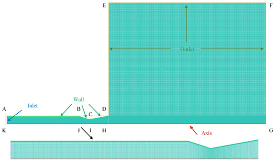
Figure 1.
Schematic diagram of calculation grid for dry powder nozzle. (A–K: the simulation zone boundary points).

Table 1.
Nozzle structure parameters/mm.
The boundary conditions, as shown in Figure 1, include a pressure inlet, pressure outlet, and non-slip adiabatic wall. The gas phase inlet pressure is set at 1.2 MPa, with the outlet environment at one atmosphere and both inlet and outlet temperatures at 300 K. The particulate phase inlet velocity matches that of the gas, with a mass flow rate of 0.001 kg/s. ABC ultrafine dry powder particles, with a particle size of 10 μm, a density of 1800 kg/m3, and a specific heat capacity of 2159 J/(kg·K), are used. Nitrogen, used as the gas-phase material, is assumed to be an ideal gas and follows the Sutherland formula. The particle injection type is surface, with the injection surface at the inlet. The injection direction is normal to the surface, employing the high-Mach-number resistance law, with the standard particle agglomeration release method.
High-quality two-dimensional structured meshes are generated using ICEM, with a refinement near the nozzle’s inner wall to meet the y+ requirement. The meshed model is shown in Figure 1, with a total mesh count of N = 125,037. To ensure the simulation’s accuracy is not influenced by the mesh size, additional meshes with counts of N = 65,493, N = 185,154, and N = 245,582 are generated for a mesh independence study. Figure 2 illustrates the variation in Mach number along the axis for different mesh counts. The low mesh count resulted in a significantly higher Mach number outside the nozzle compared to the other three, indicating a substantial deviation. Conversely, the medium and high mesh counts produced nearly identical Mach numbers. The maximum relative error in Mach number between the N = 185,154 and N = 245,582 meshes was 2.94%, within the acceptable threshold of 3%, validating mesh independence. Therefore, to optimize computational speed and reduce time costs, the N = 185,154 mesh model is selected for the numerical simulations.
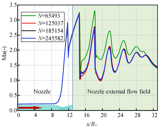
Figure 2.
x-Axial Mach number.
The simulations employed a density-based implicit solver with the AUSM flux type. Spatial discretization utilized the Green–Gauss Cell-Based gradient and second-order upwind schemes. The gas-phase flow field was first simulated in steady state. Convergence is determined when the residuals and the changes in inlet and outlet mass flow rates are less than 10−5. This steady-state flow field is then used as the initial condition for the two-phase jet simulation, where ultrafine dry powder particles are injected to simulate the supersonic two-phase jet. The detailed setting parameters are shown in Table 2.

Table 2.
Boundary conditions for supersonic jet.
To validate the model’s accuracy, numerical simulations were conducted using the geometric model (exit diameter de = 2.54, throat diameter dt = 2.289) and experimental conditions (exit Mach number Mj = 1.58, T = T0, P = P0) according to Zaman [27]. The simulation results were compared with experimental data. Figure 3 illustrates the centerline gas average velocity of the contraction-expansion nozzle at an exit Mach number of Mj = 1.58. The inverse of the centerline velocity (Uc) normalized by the nozzle exit velocity (Ue) is plotted. The experimental Ue/Uc shows an approximately linear increase over an axial distance of 15 to 35 times, and the numerical simulation results closely match the experimental data. This indicates that the numerical model presented in this study accurately simulates the supersonic gas-solid two-phase jet.
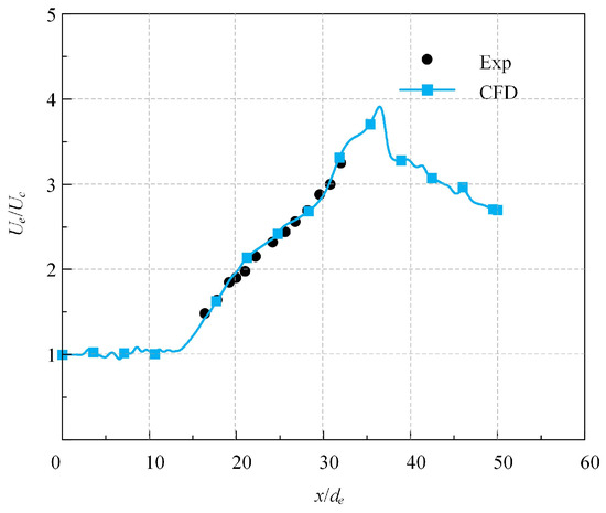
Figure 3.
Streamwise variations of centerline gas mean velocity for Mj = 1.58.
2.3. Experimental System for Ultrafine Dry Powder Jetting and Nozzle Structure Design
The experimental system for ultrafine dry powder jetting comprises two main parts: the jetting system and the control and data acquisition system, as illustrated in Figure 4. The jetting system includes air supply equipment, a dry powder sending tank, and a supersonic dry powder nozzle. The air supply equipment provides constant pressure using an air compressor as the source, with compressed air filtered and regulated before entering the dry powder sending tank, ensuring a stable gas supply. The dry powder sending tank serves as the storage container for the ultrafine dry powder fire extinguishing agent and is equipped with a pressure gauge for monitoring internal pressure. The supersonic dry powder nozzle, the core component of the jetting system, determines the jetting distance and coverage area of the ultrafine dry powder. The control and data acquisition system includes air circuit switches, powder delivery line switches, sensors, data acquisition cards, a computer, and a high-speed camera.
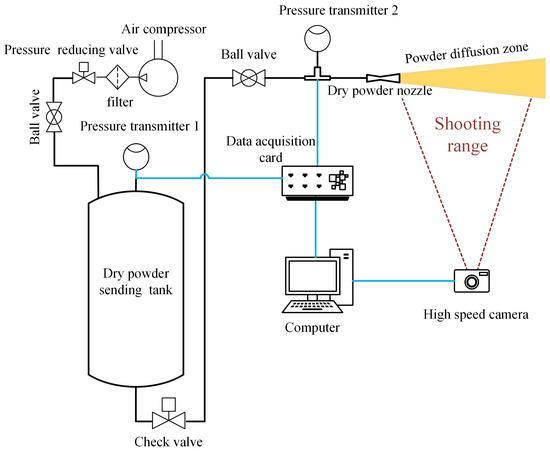
Figure 4.
Schematic diagram of ultrafine dry powder jetting system.
As seen in Figure 5, the experimental platform for ultrafine dry powder jetting is provided with a screw air compressor that produces high-pressure air carrying oil contaminants. Therefore, a filter is installed downstream of the air compressor to purify the air. High-pressure air is regulated by a pressure valve before entering the dry powder sending tank, which is equipped with a control switch, pressure gauge, and pressure transmitter. After passing through the tank, the gas–powder mixture flows through the powder line switch and pressure transmitter into the dry powder nozzle.
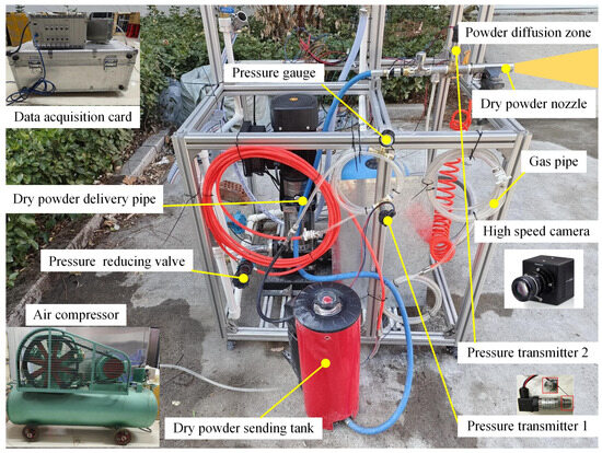
Figure 5.
Ultrafine dry powder jetting experimental platform.
Before entering the nozzle with measuring instruments, the pipeline has a small diameter and uses a bottom-draw powder tank, resulting in a high concentration of powder. Therefore, a flat diaphragm pressure transmitter is used to measure pressure changes. This transmitter, which measures pressure based on the deformation of a 316 L stainless steel diaphragm, is suitable for harsh environments and features good shock resistance, high precision, and stability. The device’s range is 0–1.6 MPa, with an output signal of 0–10 V and an accuracy of 0.5% FS, with a response time of 8 ms. The pressure signals monitored by the transmitter at the tank and nozzle entrance are recorded by the DH8302 dynamic signal testing and analysis system.
As depicted in Figure 6, the dry powder nozzle is a Laval nozzle with a typical convergent-divergent structure comprising a straight section, a convergent section, and an expansion section. Key structural parameters include the contraction angle, expansion angle, inlet diameter, throat diameter, and outlet diameter. Once these parameters are set, the lengths of the convergent and divergent sections are fixed, while the straight section length is chosen based on actual needs. The study utilizes a simplified linear flow channel nozzle for parameterized design and conducts experiments on ultrafine dry powder jetting to analyze the effects of structural and operational parameter changes on jet characteristics. Five nozzles with different structural parameters were designed and manufactured to study the influence of the semi-contraction angle (β) and semi-expansion angle (α) on the characteristics of ultrafine dry powder jets, as detailed in Table 3. Although numerical simulations show that the length of the nozzle’s straight section has a minimal effect on jet characteristics, practical two-phase flow in the pipeline encounters resistance losses. An overly long straight section significantly reduces the velocity of ultrafine powder particles, which cannot be ignored. Therefore, the straight section length was reduced from 50 mm to 3 mm during manufacturing.
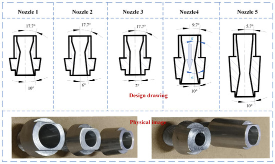
Figure 6.
Supersonic dry powder nozzle.

Table 3.
Nozzle structure parameters and experimental settings.
The air compressor inflates the powder tank through a pressure regulator, maintaining a stable internal pressure of 0.6 MPa. Before data acquisition by the testing system, the appropriate measurement channel parameters must be set based on the pressure transmitter model, including input mode, range, and sensitivity. The jetting experiments are controlled to a duration of 8 s, with repeated trials conducted. The high-speed camera starts recording image changes once the pressure sensor at the nozzle stabilizes.
3. Results and Discussion
3.1. Analysis of the Influence of Semi-Expansion Angle on Dry Powder Nozzle Jet Characteristics
The semi-expansion angle (α) of a supersonic nozzle significantly impacts the diameter ratio between the nozzle’s outlet and throat, thereby affecting the gas jet state. Studying its effect on the ultrafine dry powder fire extinguishing system’s jet characteristics is crucial. Nozzles with α = 2°, 4°, 4.5°, 6°, 8°, and 10° were selected for simulation analysis under consistent structural parameters.
From Figure 7a, as α decreases, the pressure decay rate in the nozzle’s expansion section slows down. For α ≤ 4.5°, the outlet pressure exceeds atmospheric pressure, transitioning the gas jet from an over-expanded state to an under-expanded state. This causes the gas to rapidly expand outward after exiting the nozzle, with a negative correlation between α and the degree of expansion. The number of pressure zones outside the nozzle is notably affected by α, showing an initial decrease followed by an increase. The negative pressure zone near the nozzle outlet shifts outward as α decreases. In the temperature contour of Figure 7b, the minimum temperature (Tmin) for medium semi-expansion angles (α = 4° to 6°) is significantly higher than other α values, with a substantial reduction in the low-temperature zone area outside the pipe. When α decreases to 6°, the low-temperature zone (T ≤ 100 K) completely disappears. At α = 2°, the first temperature zone outside the nozzle expands noticeably, with a lower central temperature.
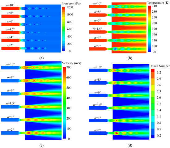
Figure 7.
Contour map of gas state parameter distribution under different semi-expansion angles. (a) Pressure contour map; (b) temperature contour map; (c) velocity contour map; (d) Mach number contour map.
The gas velocity zoning pattern in Figure 7c mirrors the pressure trend, showing a better continuity of the gas-phase flow field within the α = 4° to 6° range and uniform parameter variations. The gas-phase core jet area is the longest at α = 4.5°, and there is no significant difference in the gas flow diffusion range within the jet region. The Mach number contour in Figure 7d reveals that at α = 6°; the maximum Mach number (Mamax) is 2.7, with a weaker high Mach number area outside the nozzle. Conversely, at α = 2°, Mamax reaches 4, the highest among all α values, with the largest area of high Mach number in the first zone outside the pipe and having the strongest shock wave intensity. Medium α nozzles exhibit a lower maximum Mach number and weaker shock wave intensity compared to other angles.
Figure 8 shows that as α decreases, the peak positions of various gas-phase parameters along the axis move forward within the pipe, while outside the pipe, the peak and valley positions move in the opposite direction, following the shock wave. The radial high-speed zone maintains a ratio of over 95% to the nozzle outlet radial width, indicating that α changes do not affect the gas-phase flow field distribution at the outlet section. Overall, larger α values result in more dramatic changes in gas velocity, temperature, and Mach number curves along the axis. When α reduces to 2°, the transition of the jet state enhances the shock wave in the gas-phase flow field, leading to more significant fluctuations in gas parameters. The axial velocity curve indicates that beyond x = 110 mm, the gas velocity for medium semi-expansion angles (α = 4° to 6°) exceeds that of other groups, while the radial velocity curve shows the smoothest velocity change at α = 8°, indicating good radial distribution uniformity. Additionally, at α = 2°, the maximum Mach number outside the pipe is Mamax = 4, remaining in the supersonic range, but its peak gradually decreases with increasing jet distance until it falls below the medium α Mach number peak at x = 120 mm.
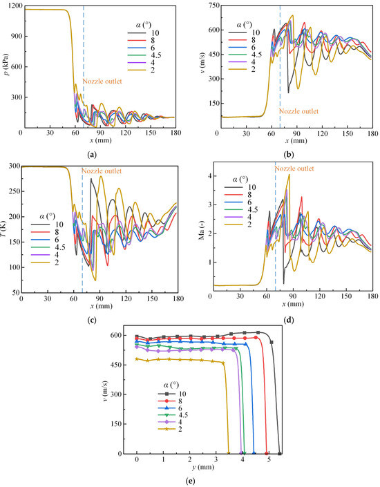
Figure 8.
Distribution curves of gas state parameters under different semi-expansion angles. (a) Axial pressure; (b) axial velocity; (c) axial temperature; (d) axial Mach number; (e) radial velocity at nozzle outlet.
Figure 9 demonstrates that as α decreases, particle velocity increases, and the jet convergence enhances, significantly reducing the dispersion range of ultrafine dry powder. At α = 2°, the under-expanded jet state leads to lower core jet particle velocities, making particles more likely to deviate from their original trajectories under the stripping action of surrounding high-speed airflow. When radial deviation tendencies surpass the inertia-driven axial progression, particles’ spatial distribution becomes more dispersed as the jet advances, closely resembling the dispersion at α = 6°. As α decreases, the particle vacuum zone near the axis gradually disappears, improving the hollow jet phenomenon.
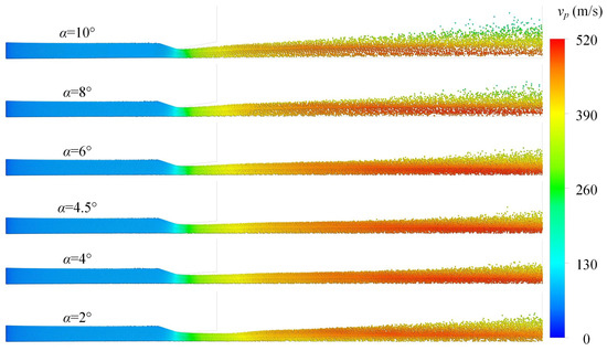
Figure 9.
Contour map of particle velocity distribution and position distribution under different semi-expansion angles.
Combining Figure 8 and Figure 9, the analysis reveals that particle velocity (vp) and α do not have a straightforward linear relationship; instead, vp initially increases and then decreases with decreasing α. In the α = 4° to 8° range, external particle jet velocity is relatively high (vp,max ≈ 510 m/s), indicating superior jet characteristics. Except for a slight decrease at x = 80 mm for α = 2°, α changes do not affect the trend of increasing particle velocity with axial distance.
As shown in Figure 10, the width of the particle core jet zone remains consistent across different α values. However, decreasing α reduces the number of radial velocity layers, enhancing jet convergence and potentially increasing jet distance. Figure 11 indicates that as α decreases, the gas expansion in the nozzle’s expansion section weakens. Although the airflow remains supersonic, its velocity significantly drops, reducing carrying capacity and gradually decreasing radial particle velocity at the nozzle outlet. The structural changes in the nozzle’s expansion section also cause the low-velocity zone at the center of the outlet to approach the axis center as α decreases, and a similar trend is observed for the near-wall low-velocity zone, which gradually disappears as the particle velocity at the outlet cross-section becomes more uniform.
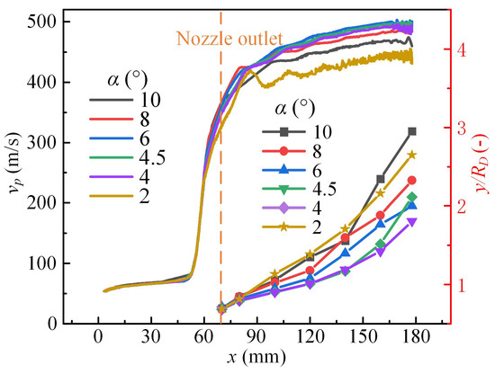
Figure 10.
Axial velocity distribution and radial width distribution curves of particles at different semi-expansion angles.
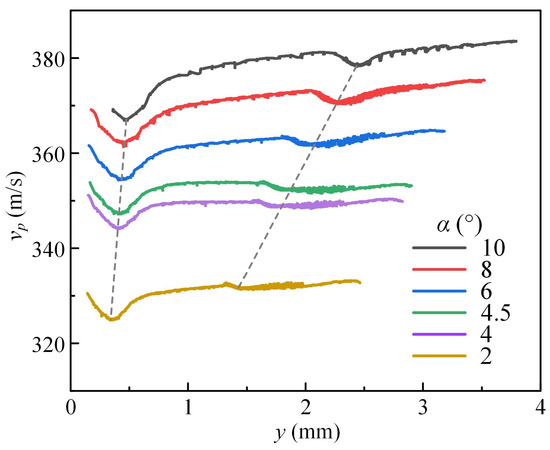
Figure 11.
Radial particle velocity distribution curve along the nozzle outlet at different semi-expansion angles.
3.2. Analysis of the Influence of Semi-Contraction Angle on Dry Powder Nozzle Jet Characteristics
When other structural parameters are kept constant, the semi-contraction angle (β) of the nozzle is varied, with values of 5.7°, 9.7°, 13.7°, 17.7°, and 21.8°, to study its effect on jet characteristics.
From Figure 12, it is evident that changing β has a relatively minor impact on the jet characteristics. The spatial distribution and magnitude of parameters within and outside the nozzle remain largely consistent. Although a smaller β effectively lengthens the nozzle body and shifts the nozzle outlet position rearward, there is no significant improvement in the jet distance of ultrafine dry powder when comparing the length and diffusion range of the jet core area. For supersonic nozzles, the influence of β on jet characteristics is minor compared to that of α.
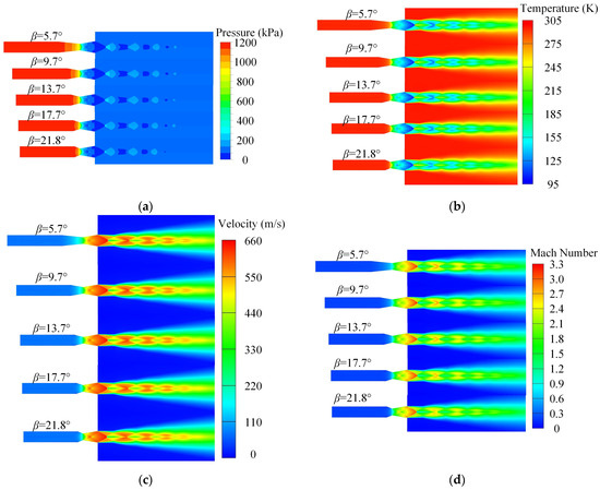
Figure 12.
Contour map of gas state parameter distribution under different semi-contraction angles. (a) Pressure contour map; (b) temperature contour map; (c) velocity contour map; (d) Mach number contour map.
Figure 13 shows the distribution of gas state parameters along the axis. As β increases, the changes in pressure peaks and valleys are minor. Near the nozzle outlet, smaller semi-contraction angles (β = 5.7° to 13.7°) result in lower gas velocity and Mach number valleys, with greater shock wave intensity. As the jet progresses, the gas-phase flow field still follows the pattern where shock wave intensity increases with decreasing β. However, for each β, the gas velocity and Mach number valleys gradually become consistent, with the gas peak values for smaller β being higher than those for larger semi-contraction angles (β = 17.7° to 21.8°). The temperature change trend is opposite to that of velocity and Mach number. The radial distribution of gas velocity at the nozzle outlet is basically the same, but as the gas converges in the contraction section, larger β results in greater impact kinetic energy loss. This leads to a significant decrease in gas velocity at the nozzle outlet, and the area of the high-velocity zone at the outlet gradually shrinks, with the radial width of the high-velocity zone being the largest at β = 9.7°.
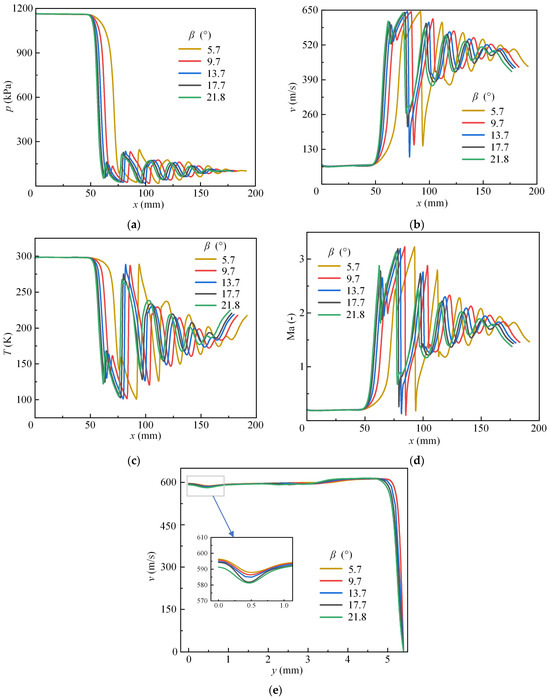
Figure 13.
Distribution curves of gas state parameters under different semi-contraction angles. (a) Axial pressure; (b) axial velocity; (c) axial temperature; (d) axial Mach number; (e) radial velocity at nozzle outlet.
Figure 14 shows that the position and speed distribution of particles under different β values are similar. The particle vacuum zone near the nozzle outlet wall does not change significantly. The maximum particle speed (vp,max) for each group is approximately 500 m/s, but the vp,max for smaller β is slightly higher than for larger β. Combining the analysis of particle speed curves in Figure 14 and Figure 15, the axial particle speed increases continuously with the jet distance. The jet area is located in the high-speed zone, and particles have considerable kinetic energy. Radially, as β increases, particle speed gradually decreases, and there is a significant speed valley at the nozzle outlet center. The vp increases with the y-axis until a second speed valley appears near the wall. Smaller β results in stronger gas carrying capacity at the outlet, causing the second speed valley to be closer to the wall and a higher proportion of high-speed particle zones. From the radial width distribution of particles outside the pipe in Figure 16, it can be observed that at the same position, larger β results in a greater diffusion range. Thus, increasing β to some extent can enhance particle diffusivity.
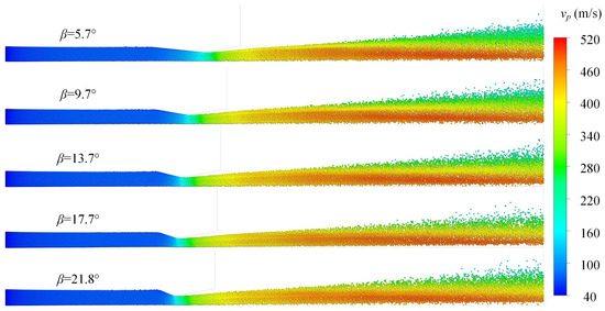
Figure 14.
Contour map of particle velocity distribution and position distribution under different semi-contraction angles.
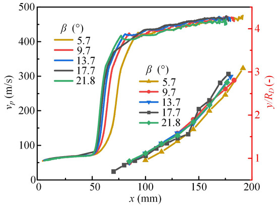
Figure 15.
Axial velocity distribution and radial width distribution curves of particles at different semi-contraction angles.
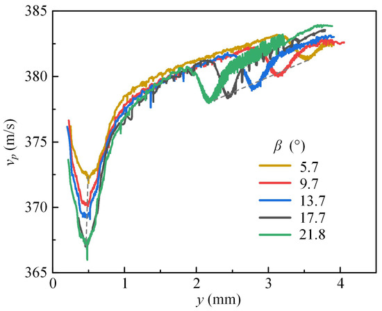
Figure 16.
Radial particle velocity distribution curve along the nozzle outlet under different semi-contraction angles.
3.3. Experimental Study of Supersonic Jets with Different Nozzle Structures
An ultrafine dry powder jet experimental platform was used to conduct experiments on three nozzles with different semi-expansion angles: Nozzle1 (α = 10°), Nozzle2 (α = 6°), and Nozzle3 (α = 2°). The pressure changes within the tank and at the nozzle inlet under different α conditions are shown in Figure 17. As α decreases, the nozzle outlet area reduces, leading to a slower rate of tank pressure decline. However, the minimum tank pressure value is the same for all groups, at 510 kPa. The peak nozzle inlet pressure decreases with the reduction of α, but the position of these peaks varies. For α = 10°, the peak occurs as soon as the tank pressure starts to drop. For α = 6°, due to insufficient air supply from the compressor, the peak is delayed and occurs at the minimum tank pressure. When α = 2°, the pressure fluctuations at the inlet are less pronounced, resulting in no significant pressure peaks during the 8 s jetting period.
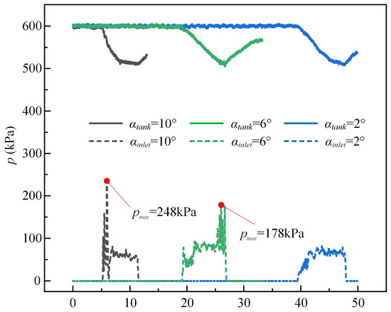
Figure 17.
Variation of tank pressure and nozzle inlet pressure under different α during jet process.
For the test, each nozzle type was tested three times under identical working conditions. The radial width (RD1) was measured from images captured by a high-speed camera, and the distance (S) between the dense part of the dry powder on the ground and the nozzle outlet was recorded post-jet. The statistical results are presented in Table 4. Figure 18 presents a series of images depicting the jet states, selected from the jet trajectories of ultrafine dry powders at different α angles, representing near-average conditions. Analysis of RD1 in Figure 18a and Table 3 indicates that as α decreases, the radial width of the dry powder jet and particle diffusivity both diminish. However, when the air flow transitions from an over-expanded to an under-expanded state at α = 2°, the reduced jet velocity facilitates particle dispersion due to external air flow peeling. The average radial width (MRD = 50.6 mm) is comparable to that at α = 6° (MRD = 50.1 mm), consistent with conclusions from Figure 8. Additionally, in the under-expanded state at α = 2°, rapid gas expansion upon exiting the nozzle results in a continuous diffusion trend of the dry powder within the x = 0~180 mm range, as opposed to the compression–expansion–compression trend observed in the other conditions.

Table 4.
Nozzle jet test data statistics.
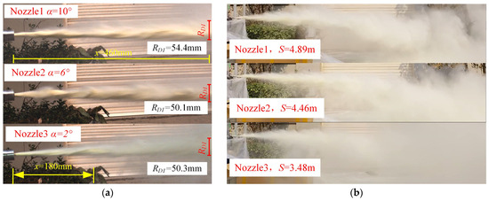
Figure 18.
Trajectory of ultrafine dry powder jet under α. (a) The front of the jet trajectory. (b) Global jet trajectory.
Due to the strong dispersibility of ultrafine dry powder, it was difficult to distinguish the core and boundary regions of the jet under light wind conditions in the later stages of the experiment. Therefore, the impact of α on the dry powder range could not be clearly observed. By measuring the distance (S) between the densely powdered area on the ground and the nozzle outlet after the jet ended, it was found that as α decreased, the dry powder range significantly shortened. The diffusion extent at the front end of the jet for α = 10° was different from that of α = 2° and α = 6°. Overall, the diffusion of dry powder was better for α = 10° than for the others.
Nozzle4 (β = 9.7°) and Nozzle5 (β = 5.7°) were tested for their jet characteristics. As shown in Figure 19, as β decreases, the valley value of tank pressure first decreases and then increases, while the peak nozzle inlet pressure changes differently. For β = 17.7° and β = 9.7°, the peak inlet pressure is equal at 238 kPa, but it drops significantly for β = 5.7° to only 119 kPa. The peak positions for all three nozzles occur when the tank pressure starts to drop, consistent with previous experimental observations.
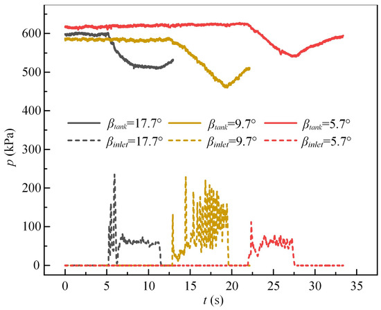
Figure 19.
Variation of tank pressure and nozzle inlet pressure under different β process.
As shown in Figure 20, a set of images of the jet state close to the mean value were selected from the jet trajectories of ultrafine dry powders under different β. Analysis indicates that the initial jet trajectories are similar for all groups. The dry powder continuously expands and compresses with the airflow, and at x = 460 mm from the nozzle outlet, the radial width of the dry powder is close (RD1 remains at 54.3 mm). This suggests that changing the nozzle contraction angle has a weak impact on dry powder diffusivity, which aligns with the conclusions from Figure 14. Additionally, the overall jet trajectories match the data in Figure 15, indicating that the particle speed in the core jet area is consistent across different β values, and the ultrafine dry powder range is also similar (S ≈ 4.9 m).
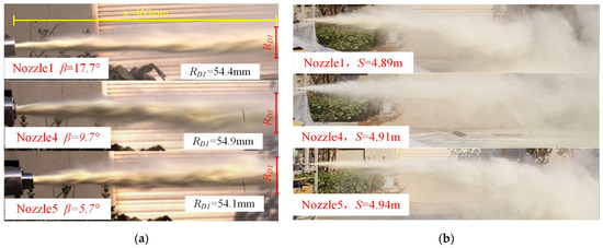
Figure 20.
Trajectory diagram of ultrafine dry powder jet under different β. (a) The front of the jet trajectory. (b) Global jet trajectory.
4. Conclusions
This study investigates the influence of the structural parameters of expansion angle (α) and semi-contraction angle (β) on the behavior of compressible gas flow and particle distribution trajectories in ultrafine dry powder nozzles using the SST k-ω turbulence model and the DPM model for gas-solid two-way coupled numerical simulations. The conclusions derived from both simulation and experimental approaches are as follows:
- (1)
- For supersonic nozzles with gas-solid two-phase jets, altering the semi-contraction angle has minimal impact on the gas-phase flow field. The peak and valley values of gas-phase state parameters remain approximately the same, and the increase in particle jet velocity is minor. The effect of changing the expansion angle on jet characteristics is significantly greater. Under constant inlet pressure, a decrease in the expansion angle enhances particle collimation. Specifically, when the semi-expansion angle α = 2°, the gas jet is in an under-expanded state, making particles more prone to dispersion due to the stripping effect of the surrounding high-speed airflow. At α = 4.5°, the gas jet core region is the longest, providing the optimal particle acceleration effect.
- (2)
- Reducing the expansion angle alters the gas jet state. When α = 2° (under-expanded state), the dry powder exhibits a continuous diffusion trend within the x = 0 to 180 mm range, contrasting with the compression-expansion trend observed in over-expanded states. Globally, the diffusion of dry powder is more effective at α = 2° compared to α = 6°.
- (3)
- The experimental findings are largely consistent with the numerical simulation patterns. An excessively small expansion angle α is detrimental to increasing the range of the dry powder jet, and changes in the semi-contraction angle β have a relatively minor impact on the characteristics of the supersonic jet. When the structural parameters are the same, the diffusion and range of dry powder are identical for different semi-contraction angles β.
These findings provide a comprehensive understanding of the influence of nozzle design parameters on the characteristics of ultrafine dry powder jets, offering valuable insights for optimizing nozzle structures in practical applications.
Author Contributions
Conceptualization, H.G.; methodology, H.G.; software, H.G.; validation, H.G.; formal analysis, H.G.; investigation, X.Z.; resources, P.Z.; data curation, H.G.; writing—original draft preparation, H.G.; writing—review and editing, H.G.; visualization, Y.L.; supervision, H.G.; project administration, C.Z.; funding acquisition, X.Z. All authors have read and agreed to the published version of the manuscript.
Funding
This research was funded by the key research and development of Shandong province, China, grant number 2019SDZY01.
Data Availability Statement
The data that support the findings of this study are available on request from the corresponding author.
Conflicts of Interest
The authors declare no conflicts of interest.
References
- Hassan, S.; Björn, K. Pneumatic Conveying of Wood Powder by Using a Steam-Jet Ejector. Biomass Bioenergy 2000, 19, 103–117. [Google Scholar] [CrossRef]
- Miyata, M.; Tamura, T.; Higuchi, Y. Development of Hot Metal Dephosphorization with Lime Powder Top Blowing: Part 1. Low Blowing Rate. ISIJ Int. 2017, 57, 1756–1761. [Google Scholar] [CrossRef]
- Varadaraajan, V.; Mohanty, P. Design and Optimization of Rectangular Cold Spray Nozzle: Radial Injection Angle, Expansion Ratio and Traverse Speed. Surf. Coat. Technol. 2017, 316, 246–254. [Google Scholar] [CrossRef]
- Cao, C.; Li, W.; Zhang, Z.; Yang, X.; Xu, Y. Cold Spray Additive Manufacturing of Ti6Al4V: Special Nozzle Design Using Numerical Simulation and Experimental Validation. Coatings 2022, 12, 210. [Google Scholar] [CrossRef]
- Gabor, T.; Akin, S.; Jun, M.B.-G. Numerical Studies on Cold Spray Gas Dynamics and Powder Flow in Circular and Rectangular Nozzles. J. Manuf. Process. 2024, 114, 232–246. [Google Scholar] [CrossRef]
- Mat, M.N.H.; Asmuin, N.Z.; Basir, M.F.M.; Goodarzi, M.; Rahman, M.F.A.; Khairulfuaad, R.; Jabbar, B.A.; Kasihmuddin, M.S.M. Influence of Divergent Length on the Gas-Particle Flow in Dual Hose Dry Ice Blasting Nozzle Geometry. Powder Technol. 2020, 364, 152–158. [Google Scholar] [CrossRef]
- Okuda, S.; Choi, W.S. Gas-Particle Mixture Flow in Various Types of Convergent-Divergent Nozzle. J. Chem. Eng. Jpn. 1978, 11, 432–438. [Google Scholar] [CrossRef]
- Zhong, L.; Lei, J.; Zuo, Z.; Tu, J.; Deng, J.; Lei, Z.; Zhao, M.; Hua, Y. Simulation Analysis of the Decontamination Effect of Different Nozzles Abrasive Jet Based on CFD-DEM. Part. Sci. Technol. 2023, 41, 864–875. [Google Scholar] [CrossRef]
- Hong, C.; Yang, R.; Huang, Z.; Liu, W.; Chen, J.; Cong, R. Experimental Investigation on Coal-Breakage Performances by Abrasive Nitrogen-Gas Jet with a Conical Nozzle. Int. J. Rock Mech. Min. Sci. 2021, 142, 104781. [Google Scholar] [CrossRef]
- Zhang, L.; Feng, Y.; Wu, S.; Jia, H. Numerical Study of the Effect of Primary Nozzle Geometry on Supersonic Gas-Solid Jet of Bypass Injected Dry Powder Fire Extinguishing Device. Fire 2024, 7, 45. [Google Scholar] [CrossRef]
- Wu, X.; Zhu, R.; Wei, G.; Dong, K. Influence of the Carrier Gas Species on CaO-Gas Mixed Injection in the EAF Steelmaking Process. Met. Mater Trans B 2019, 50, 2389–2402. [Google Scholar] [CrossRef]
- Wang, Q.; Pang, Z.; Tian, C.; Chen, J. New Design Method of a Supersonic Steam Injection Nozzle and Its Numerical Simulation Verification. ACS Omega 2023, 8, 44485–44496. [Google Scholar] [CrossRef] [PubMed]
- Lupoi, R.; Meyer, M.; Wits, W.W.; Yin, S. The Role of Particles Flow Characteristics in the Performance of Cold Spray Nozzles. CIRP Ann. 2020, 69, 189–192. [Google Scholar] [CrossRef]
- Kudryavtsev, A.; Shershnev, A.; Rybdylova, O. Numerical Simulation of Aerodynamic Focusing of Particles in Supersonic Micronozzles. Int. J. Multiph. Flow 2019, 114, 207–218. [Google Scholar] [CrossRef]
- Miao, B.; Chen, F. Optimization Simulation of Ultrafine Dry Powder Blow-Assisted Pipe Based on CFD. Math. Probl. Eng. 2022, 2022, 8304007. [Google Scholar] [CrossRef]
- Ding, H.; Zhuo, C.; Deng, H.; Hu, W.; Chen, X. Numerical Study on Coupled Flow Characteristics of a Gas-Solid Two-Phase Jet in a Supersonic Crossflow. Int. J. Multiph. Flow 2023, 168, 104583. [Google Scholar] [CrossRef]
- Yu, H.; Yang, S.; Hu, J.; Wang, H. CFD Study of Gas-Powder Injection Characteristics in a Novel Lance with Supersonic Shrouding Jet. Chem. Eng. J. 2024, 481, 148470. [Google Scholar] [CrossRef]
- Yu, H.; Yang, S.; Hu, J.; Wang, H. Jet Penetration and Particle Dispersion Behaviors of Supersonic Gas–Solid Oxygen Jet under High Ambient Temperature. Appl. Therm. Eng. 2024, 242, 122502. [Google Scholar] [CrossRef]
- Cruz, N.; Briens, C.; Berruti, F. Supersonic Attrition Nozzles in Gas–Solid Fluidized Beds. Chem. Eng. Process. Process Intensif. 2010, 49, 225–234. [Google Scholar] [CrossRef]
- Cruz, N.; Briens, C.; Berruti, F. Effect of Thrust on Supersonic Gas Jet Penetration in Gas–Solid Fluidized Beds. Powder Technol. 2011, 214, 38–46. [Google Scholar] [CrossRef]
- Liu, F.; Sun, D.; Zhu, R.; Li, Y. Characteristics of Flow Field for Supersonic Oxygen Multijets with Various Laval Nozzle Structures. Metall. Mater. Trans. B 2019, 50, 2362–2376. [Google Scholar] [CrossRef]
- Li, M.; Li, L.; Zhang, B.; Li, Q.; Wu, W.; Zou, Z. Numerical Analysis of the Particle-Induced Effect on Gas Flow in a Supersonic Powder-Laden Oxygen Jet. Metall. Mater. Trans. B 2020, 51, 1718–1730. [Google Scholar] [CrossRef]
- Sun, H.; Yu, H.; Yang, S.; Hu, J.; Wang, H. Four-Way Coupled Eulerian-Lagrangian Study of Phase Interaction Mechanism in the Supersonic Gas-Solid Two-Phase Flow. Chem. Eng. J. 2023, 473, 145265. [Google Scholar] [CrossRef]
- Yang, Q.; Yang, S.; Yu, H.; Wang, H. Impact of Laval Nozzle Structure on the Flow Characteristics of Supersonic Gas-Solid Two-Phase Flow. Powder Technol. 2024, 439, 119657. [Google Scholar] [CrossRef]
- Shi, H.; Wang, X.; Xiang, Q.; Zhang, G.; Xue, L. Experimental and Numerical Study of the Discharge Performance of Particle-Laden Turbulent Flow. J. Mar. Sci. Eng. 2022, 10, 85. [Google Scholar] [CrossRef]
- Zhang, L.; Yu, Q.; Liu, T.; Feng, Z.; Sun, M.; Jin, H. Coupled Modeling and Numerical Simulation of Gas Flows Laden with Solid Particles in de Laval Nozzles. Shock Waves 2022, 32, 213–230. [Google Scholar] [CrossRef]
- Zaman, K.B.M.Q. Asymptotic Spreading Rate of Initially Compressible Jets—Experiment and Analysis. Phys. Fluids 1998, 10, 2652–2660. [Google Scholar] [CrossRef]
Disclaimer/Publisher’s Note: The statements, opinions and data contained in all publications are solely those of the individual author(s) and contributor(s) and not of MDPI and/or the editor(s). MDPI and/or the editor(s) disclaim responsibility for any injury to people or property resulting from any ideas, methods, instructions or products referred to in the content. |
© 2024 by the authors. Licensee MDPI, Basel, Switzerland. This article is an open access article distributed under the terms and conditions of the Creative Commons Attribution (CC BY) license (https://creativecommons.org/licenses/by/4.0/).