1. Introduction
Cross-flow fans (CFFs) are a type of fan turbomachinery that are characterised by their large length-to-diameter ratio and ability to generate a primarily uniform flow along their length at low rotational speeds and low noise emission. Therefore, they are predominantly employed in heating, ventilation, and air conditioning (HVAC) systems. However, the application scope of CFFs extends to industrial applications such as highly specialised laser modules in the semiconductor industry. These applications require high CFF performance to maintain consistent and high-quality laser output through the gas circulation system. In [
1], the authors presented the bearingless CFF, which allows for wear- and friction-free CFF operation inside a hermetically sealed chamber with high-speed capability, supported by high drive power available on both rotor sides. To enhance the fluid dynamic performance of bearingless CFF’s within a given, constrained installation space (as shown in
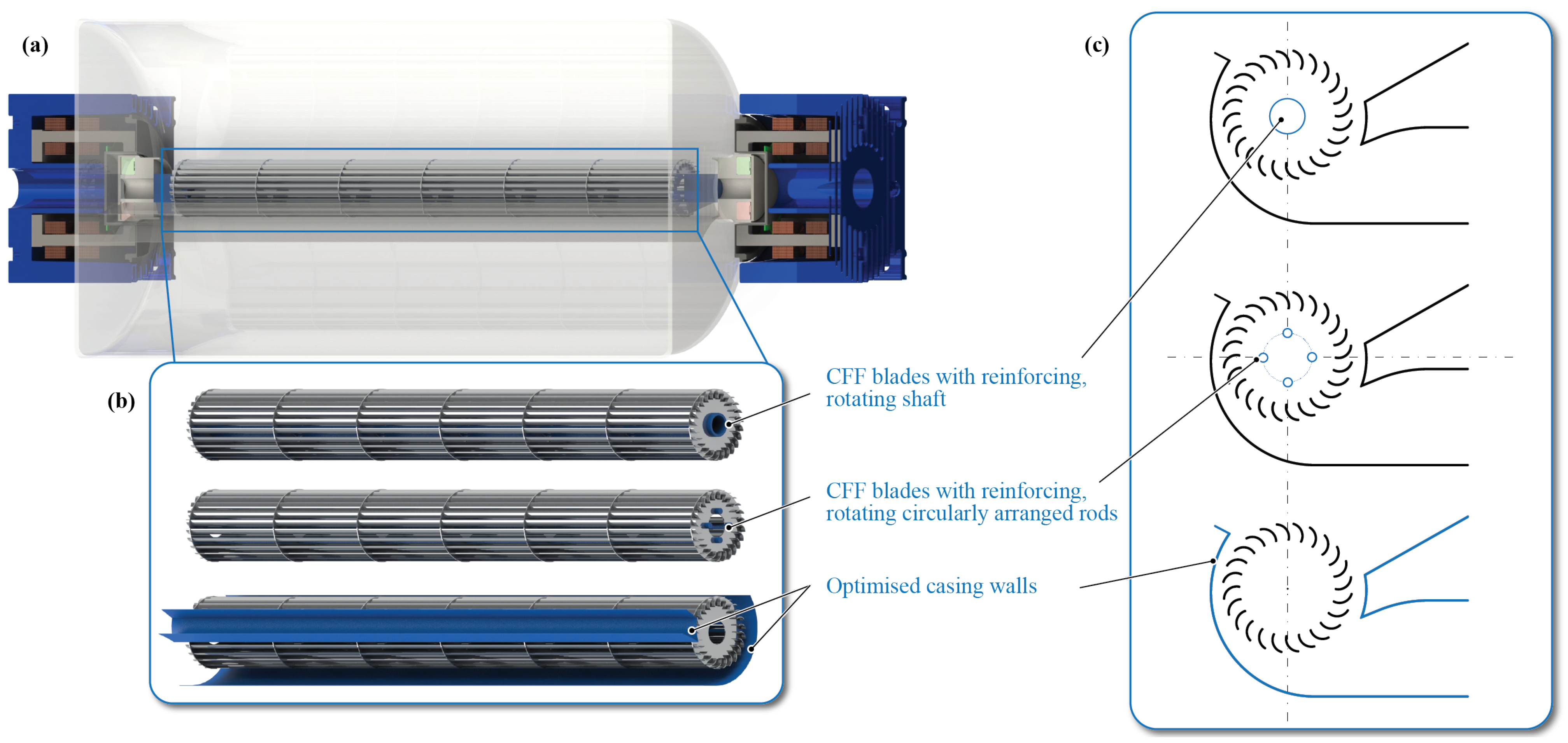
Figure 1a), this paper conducts a Computational Fluid Dynamics (CFDs)-based design optimisation supported and verified by measurements. On the one hand, design measures are investigated to increase the CFF’s mechanical strength through introducing stiffness increasing shafts. This shifts the critical bending resonance frequency, which currently limits the maximum achievable rotational speed to a higher frequency, thus enabling stable CFF operation at increased rotational speeds. On the other hand, design changes of the CFF casing walls are evaluated to improve its fluid dynamic performance, particularly to reduce recirculation losses between the rotating blades and the static casing walls. The investigated design measures are depicted in
Figure 1b,c.
In industrial applications such as deep ultraviolet (DUV) lithography systems, CFFs are part of the gas circulation system. DUV lithography systems use short-wavelength ultraviolet (UV) light, typically provided by an argon fluoride (ArF) or krypton fluoride (KrF) excimer laser, to project intricate patterns onto silicon wafers for the precise fabrication of semiconductor devices. CFFs, with their cylindrical shape and tangential flow direction, are compactly integrated within the limited space constraints of the excimer laser to uniformly circulate and cool the laser gas [
2,
3,
4]. Increasing the CFF’s performance can positively impact various aspects of laser performance, including cooling efficiency, gas circulation, flow stability and reliability, which contributes to achieving consistent and high-quality laser output. Hence, increasing the CFF’s performance is a direct enabler for improving the excimer lasers’s performance.
To increase the CFF’s performance by increasing its rotational speed, the bending resonance frequency emerges as a critical factor, since CFFs typically consist of long, slender blades that are prone to bending vibrations. When the rotational speed approaches or exceeds the bending resonance frequency, it can lead to significant structural vibrations and potentially cause mechanical damage to the CFF blades. In [
1], the authors provided an in-depth explanation of how the bending resonance frequency emerges as the speed and performance-limiting factor for the bearingless CFF. With the proposed bearingless motor technology, both the bearing and drive functionalities are integrated into a single motor unit, with a drive motor implemented on each side of the CFF rotor. This setup enables contactless levitation and rotation, with each motor independently controlling the bearing forces on its respective rotor side. The drive torque is generated by both motors, with a reference torque current passed from the primary to the secondary motor. Thus, each motor contributes half of the required drive torque, ensuring an even distribution of the load. A detailed description of the operating principle can be found in [
1]. It is emphasised that the magnetic bearing can only withstand forces and allow displacements to a limited extent. In [
5], the authors proposed a method to shift the detrimental bending resonance frequency to higher frequencies through the design of a novel CFF rotor. The rotor features additional mechanical decoupling elements with low bending stiffness, allowing resonance frequencies to be surpassed without causing damage to the CFF blades and enabling rotor operation at a 40% higher rotational speed. Moreover, with magnetic bearings, it becomes feasible to implement complex control algorithms to actively control specific vibration modes. This offers the capability to dampen, bypass, or eliminate resonance frequencies, such as the bending resonance frequency. In the literature, different approaches have been investigated, typically for massive shafts and Jeffcott rotors. In [
6], an optimum compensator control design method was proposed to obtain the minimum resonance peak of the rotor when passing the first bending critical speed. To operate a maglev motor above the bending critical speed, ref. [
7] designed a
synthesis controller and experimentally verified that the rotor passed through the first bending mode frequency. A
synthesis controller was designed by [
8] as well to achieve active damping of the rotor’s bending mode and pass through its critical speed. Using a mixed PID control method based on mode separation, ref. [
9] showed by simulation that the flexible rotor can pass the first bending critical speed.
This paper examines two additional methods for enhancing the CFF’s performance that can be implemented alongside the previously mentioned damping techniques. From a fluid dynamical point of view, the CFF’s non-axissymmetric flow profile is defined by the transverse double passage of the fluid through the rotating blades and the formation of an eccentric vortex within the impeller. There is not yet a general approach or analytical description to accurately model the aerodynamic features and loss mechanisms of CFFs nor to precisely predict their performance. Several different investigations about CFFs were conducted using analytical modelling, numerical simulation, and experimental data [
10,
11,
12,
13]. To analytically determine the CFF performance curves for a given geometry, refs. [
14,
15,
16] used the mean streamline analysis with empirical data. Numerous numerical and experimental studies have been conducted to analyse the influence of the CFF blades’ [
17,
18,
19] and casing walls geometry [
20,
21,
22,
23] on the CFF performance. A particular focus lies in visualising the complex flow patterns by means of CFDs and analysing the velocity vectors and pressure gradients to draw conclusions about CFF performance, efficiency, and loss mechanisms [
24,
25,
26,
27]. In [
28], Stereo Particle Image Velocimetry (SPIV) was presented as an experimental flow visualisation technique to examine the influence of CFF casing geometries. In a recently published review paper on the performance and efficiency of CFFs [
29], it was concluded that optimising and enhancing their performance remains a challenging task. To boost the CFF’s efficiency, it is crucial to improve its structural characteristics, aerodynamic properties, and acoustic behaviour.
Compared to existing approaches in CFF analysis, this study integrates fluid dynamics, rotor dynamics, and various aspects of the mechatronic system through experimental measurements. Particularly, increasing the performance of bearingless CFFs presents several challenges concerning fluid dynamics, rotor dynamics (mechanical strength and rotor vibrations), and the influence on the magnetic bearing. The fluid forces can lead to displacements of the magnetically levitated rotor, requiring measures to prevent collisions with the static casing walls by maintaining a certain safety distance. The goal of this paper is to optimise the CFF performance in terms of output pressure and flow while considering the different effects on the bearingless motor system.
The paper is organised as follows:
Section 2 presents the methods used for the CFF rotor and casing wall optimisation, including the fundamental aerodynamics, implemented CFD model, simulated modal analysis, and measurement setup.
Section 3 reveals and discusses the results for the different rotor and static casing walls design modifications.
Section 4 summarises the main conclusions.
2. Methods for CFF Analysis
2.1. Fundamental Aerodynamics
This section explains the operating principle of CFFs from a fluid dynamical point of view, particularly to underline the loss mechanisms associated with the characteristic eccentric vortex. The goal of this analysis is to explore methods for enhancing the performance of the CFF by modifying both the rotor and static casing walls within given space constraints. Regarding the rotor modifications, the primary focus is on increasing mechanical stiffness through the integration of reinforcing shafts and evaluating their impact on fluid dynamic performance. In terms of the static casing walls, the emphasis is on optimising the eccentric vortex region to reduce recirculation losses.
Generally, the energy increase of a fan turbomachinery represents the change in energy of the fluid passing through the fan from the inlet to the outlet side, i.e., from the suction to the discharge region. This energy increase is typically defined in terms of total pressure
and can be expressed as the sum of both the static and dynamic pressure components as the first form of Euler’s fluid machine equation:
where
c is the absolute,
u is the circumferential,
w is the relative velocity, and
is the density. The geometric sum of the circumferential and relative velocity gives the absolute velocity, which defines the second form of Euler’s fluid machine equation as
For CFFs, the flow field is predominately two-dimensional, i.e., perpendicular to the impeller axis. It is described by the fluid entering the forward curved blades tangentially on the suction side, passing through the interior part of the impeller, and then exiting the blades tangentially on the discharge side. Hence, the rotating blades are passed twice by the fluid, and an eccentric vortex is formed within the impeller. The eccentric vortex is a characteristic flow pattern inherent to the design and operation of CFFs.
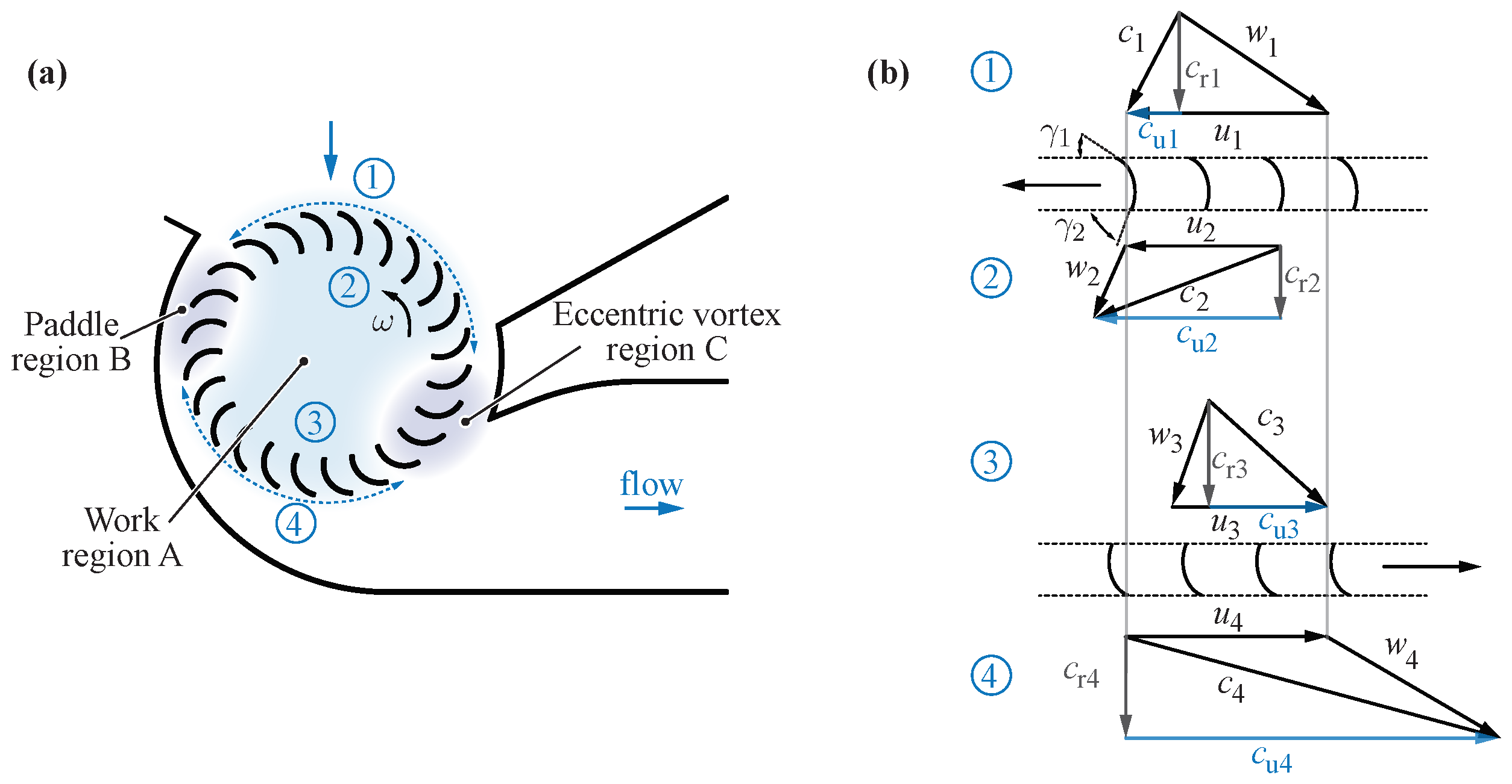
To explain the fundamental kinematics and energy transfer processes for CFFs,
Figure 2 is used. It is based on [
14], who describe in detail the throughflow and loss characteristics of the CFF by the mean streamline analysis. The analysis has the underlying assumption that the flow within the fan can be divided into three regions (depicted as work region A, paddle region B, and eccentric vortex region C in
Figure 2a) and can be analysed independently. However, the flow is strongly influenced by the operating conditions and the fan geometry, which can be difficult to parameterise.
The principal throughflow of the impeller is represented by region A, where the majority of the beneficial work is conducted, and is described by the velocity triangles in
Figure 2b. Using Equation (
2), the ideal total pressure increase across the CFF impeller
is given by the sum of the first and second stage total pressure increase as
The actual total pressure increase
is then given by
where the pressure losses
are an unknown parameter consisting of several different loss mechanisms. In [
15], the most important loss models of the mean streamline analysis are summarised as skin friction, incidence expansion, enlargement, and recirculation losses. As explained in [
14], the CFF blades in region B act essentially like a paddle wheel; hence, the energy transfer is comparatively low and inefficient. Region C represents the eccentric vortex, which consists of the recirculating flow and is primarily responsible for energy dissipation and the shaping of region A.
From the CFFs operating principle described above, it becomes clear that introducing interior obstructions within work region A, such as mechanically reinforcing shafts, causes flow disturbances and additional losses. However, these stiffness-increasing measures have a significant impact on the CFF’s vibration behaviour, especially its bending resonance frequency.
Various diameters of reinforcing shafts have been studied, as depicted in
Figure 3a for a single central shaft and in
Figure 3b for circularly arranged rods. Regarding the casing wall optimisation, its key geometric parameters are presented in
Figure 3c, and different variations have been investigated.
2.2. Computational Fluid Dynamics
For the CFDs analysis, planar 2D simulations were conducted, as the flow profile of the CFF remains predominantly uniform along its length. The numerical model utilised has been presented by the authors in [
1]. The transient simulation model has been developed with air under ambient pressure and modelled as incompressible, since the expected Mach numbers are below 0.3 (subsonic). Furthermore, the sliding mesh method was employed for the calculations, with the
SST model used for turbulence modelling. A detailed description, including a convergence study involving mesh and time step parameters for the transient CFF CFDs simulation can be found in [
1], which led to a robust model with optimised mesh and time step settings.
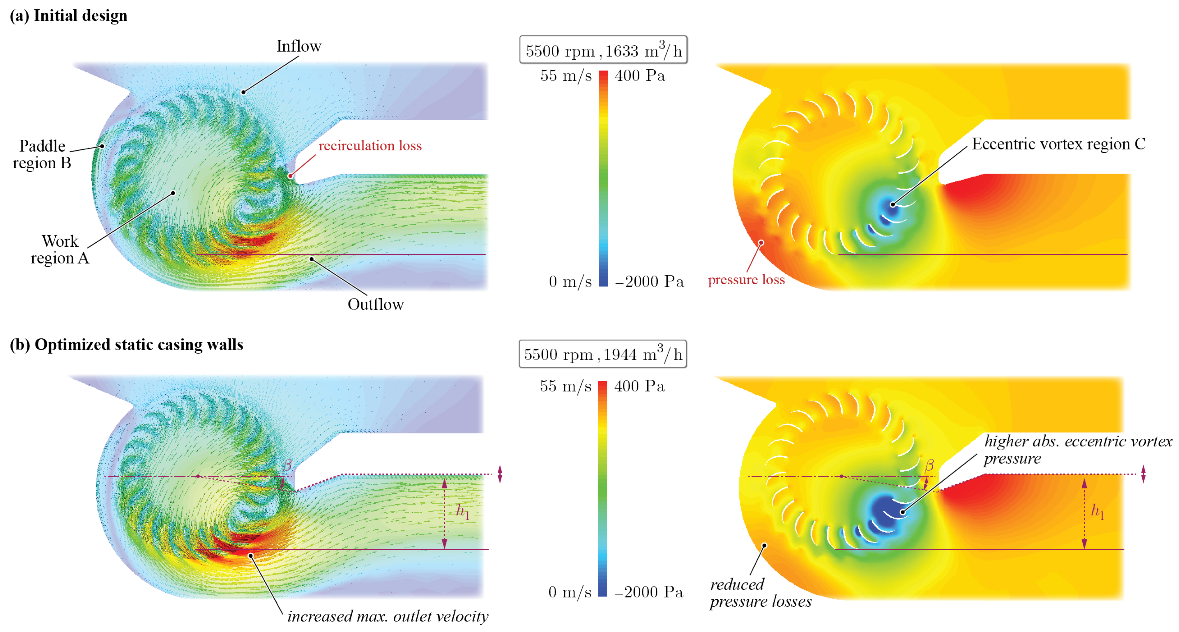
Figure 4 illustrates the velocity and pressure profiles resulting from the CFD simulation for the initial CFF geometry at 5500 rpm and 1633
(high-flow point). The velocity vectors provide a visual representation of the key fluid dynamic features, highlighting the inflow and outflow regions, as well as the non-axisymmetric flow profile. Additionally, the pressure profile vividly illustrates the presence of the eccentric vortex.
For the forthcoming comparisons and performance evaluations, the dimensionless flow
and pressure
coefficients are evaluated from the simulated physical flow
Q and pressure values
according to
where
and
correspond to the CFF blades’ diameter and length, and
u corresponds to the circumferential velocity
with
n being the CFF’s rotational speed and
where
is the density of air. Introducing shafts within the CFF impeller changes its bending resonance frequency and can increase the rotational speed at which it can be operated. The dimensionless pressure and flow coefficients allow us to extrapolate the physical pressure and flow for operating points at different rotational speeds according to
and
with
representing the extrapolated flow and
representing the extrapolated pressure derived from the CFDs results at different rotational speeds of
.
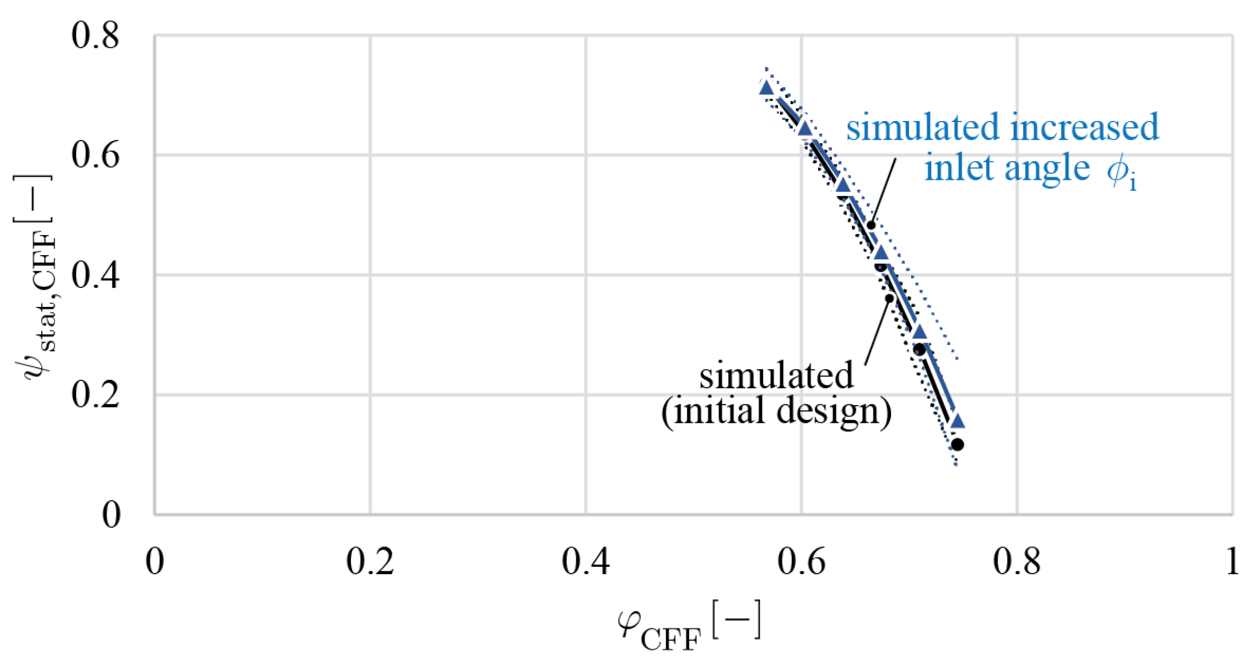
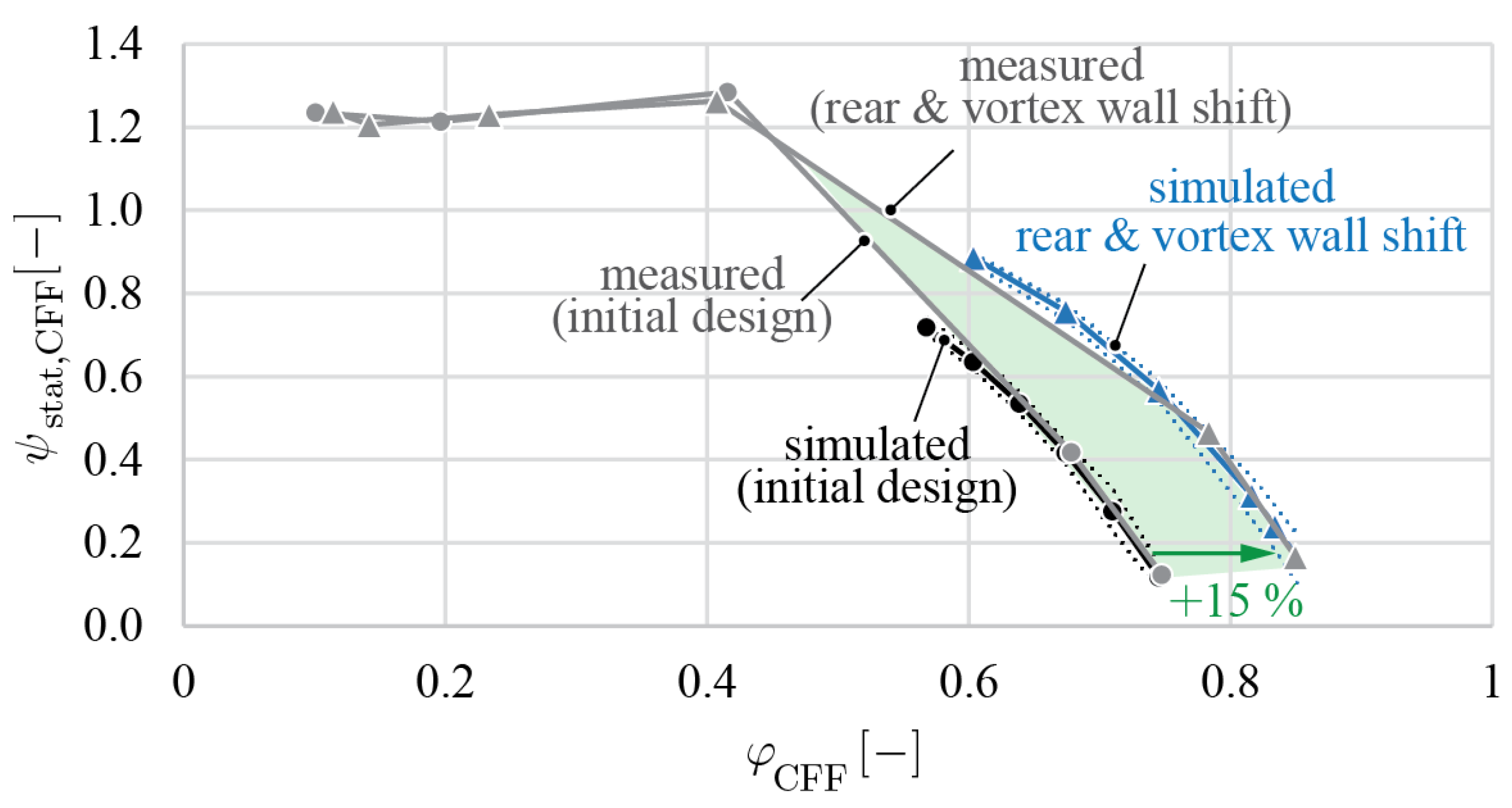
The CFDs simulation was conducted for several high-flow operating points and compared to measured data points in
Figure 5. To derive the flow rate from the 2D simulation, the inlet velocity was multiplied by the cross-sectional area defined by the inlet channel’s height and width. The dotted lines of the simulated curve mark the pressure fluctuation in the CFD simulation during the final turn, indicating convergence and a stable eccentric vortex region, i.e., no pressure pulsations. As described in [
1], an operation point converges after approximately six turns, while one turn (a 360° rotation of the fan blades) corresponds to 66.67 numerical time steps. It can be seen that the simulated and measured data points agree very well.
For this study, the simulated operating points of the different design adaptations were focused on the high-flow regime. At low-flow operating points, the implemented incompressible CFDs model (justified with the expected subsonic speeds of Mach numbers below 0.3) predicted strong pressure fluctuations, which inadequately represent the physical conditions. In [
30], it was observed that as the flow decreases, the eccentric vortex region C expands. Consequently, it is more challenging for the inlet flow to efficiently penetrate work region A of the CFF, which exacerbates the non-uniformity and amplifies the pressure pulsations within region C. In [
31], it was concluded as well that the dominant frequency responsible for the velocity and pressure fluctuations in the CFF is mainly generated due to the unsteadiness of the eccentric vortex. The flow in the low-flow region was described as strongly unsteady, unstable, and three-dimensional in [
16]. Therefore, the following simulations focus on numerically stable, high-flow operating points, aligning with the typical CFF application for generating uniform flow patterns along their length.
To quantitatively compare the modified and initial CFF design, the simulated operating points at the same dimensionless static inlet pressure were evaluated to determine the change in fluid flow as .
2.3. Simulated Modal Analysis
A modal analysis was performed on the CFF rotor modifications with various shafts to estimate the system’s first bending resonance frequency to draw conclusions about the maximum achievable rotational speed. It is described in more detail in [
1]. This theoretical assessment of different shaft sizes and arrangements assists in determining which prototypes to commission.
2.4. Measurement Setup
The CFD simulations and experimental measurements were conducted for a CFF with
and
. The pressure–flow measurements were performed with air under ambient pressure on a test rig presented in detail in [
1]. It consists of an inlet ventilation duct equipped with a variable inlet grid for setting different operating points, along with a pressure and a flow sensor. Characteristic pressure–flow curves can be recorded for various design modifications.
For the rotor dynamic measurements, the displacements of the rotor magnet within the magnetic bearing were evaluated using built-in sensors in the bearingless motor. The bending resonance frequency was identified by the rapid increase in radial displacements as it was approached.
4. Conclusions
This study conducted a CFDs-based optimisation of measures to enhance the performance of bearingless CFFs, which is particularly important for certain industrial applications in the semiconductor industry. Modifications of the CFF rotor and static casing walls were investigated. Various prototypes were derived from the simulation results, which were then commissioned and tested.
It is concluded that to enhance CFF performance, the principal throughflow within the CFF impeller must remain unobstructed for fluid flow, and the eccentric vortex region must be stabilised through careful design of the vortex wall, while the paddle region (located on the fluid inlet side of the rear wall) is largely irrelevant for CFF performance.
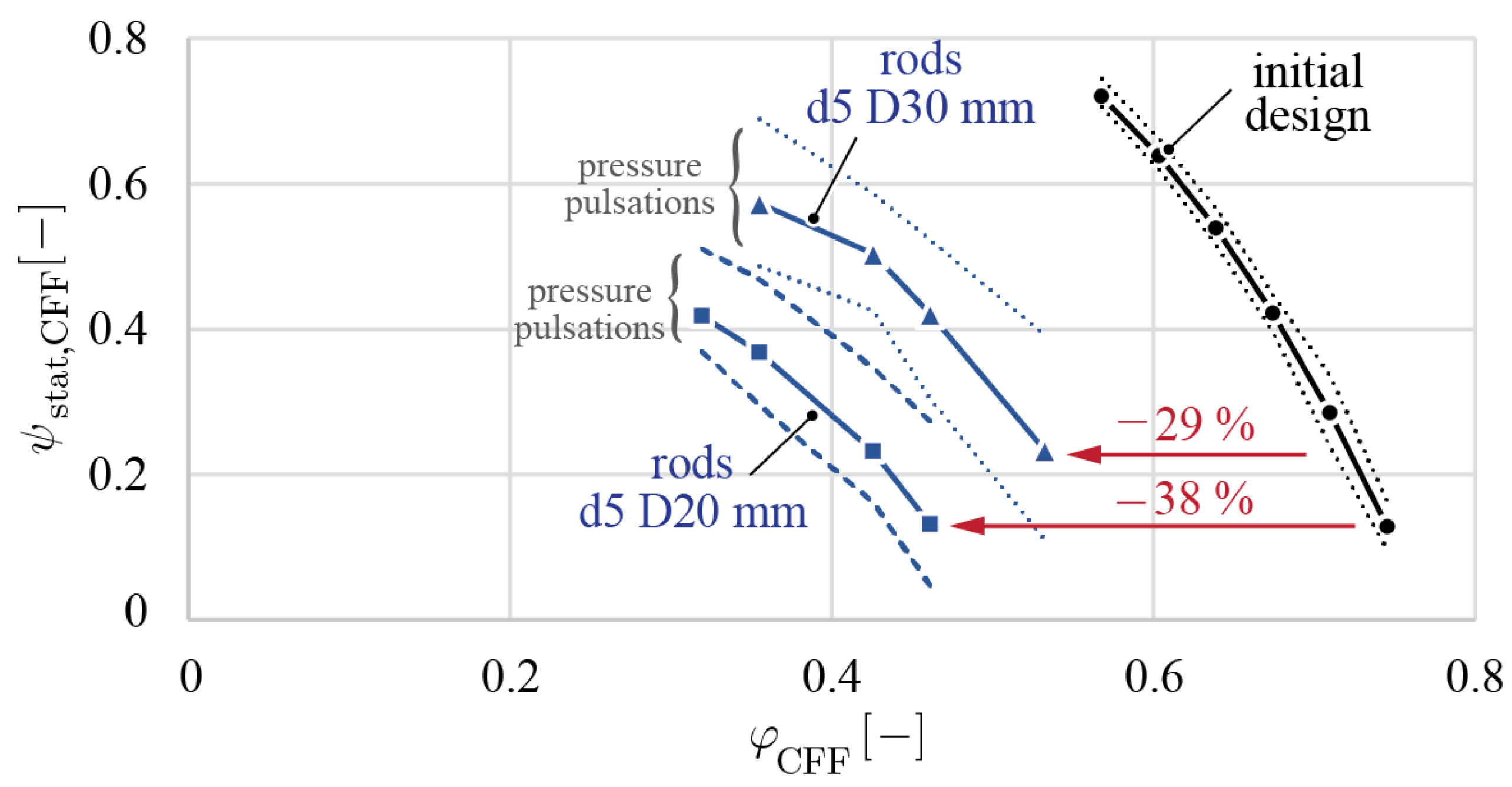
Regarding the rotor modifications, introducing different dimensions of central shafts and circularly arranged rods as rotor stiffening methods within the CFF impeller impacts both the rotor dynamic and fluid dynamic performance. Specifically, a stainless steel shaft with a diameter of 20 mm shifts the critical bending resonance frequency of the CFF blades 42% higher. However, CFD simulations and experimental measurements showed that the flow dropped by 61%. The results indicate that while the reinforced CFF rotors achieved a higher rotational speed, this came at a significant cost to the fluid dynamic performance. Specifically, the increase in rotational speed did not compensate for the substantial reduction in fluid flow for all tested reinforced CFF rotors. This trade-off highlights the complexity of optimising both the mechanical and fluid dynamic aspects of the CFF rotor. The CFD investigation of circularly arranged rods additionally revealed that the rods induce significant, undesired pressure pulsations within the eccentric vortex. These pulsations lead to unstable flow patterns, which are not desired for their application in gas circulation systems of excimer lasers.
Regarding the casing wall modifications, the CFF performance is highly sensitive to changes in geometric parameters, particularly the vortex wall, as the casing walls directly influence the airflow path through the fan. A successful simulated and measured performance increase of up to 22% was achieved.
In summary, the paper’s results demonstrate that the performance of the bearingless CFF can be enhanced by modifying the geometry of the casing walls, without altering the rotor or the bearingless motor. To balance the advantages of increased critical speeds with the disadvantages of reduced fluid flow, especially in industrial applications where maximising fluid performance is crucial, future research should focus on developing hybrid approaches that combine rotor stiffening with fluid dynamic enhancements. Potential solutions could include the use of advanced materials that provide both stiffness and fluid dynamic performance, the redesign of the CFF blades, or the integration of rotor dynamic solutions that do not negatively impact the CFF’s fluid dynamics.
