1. Introduction
Wheeled and tracked drive mechanisms exhibit distinct advantages in different scenarios. The former excel on paved surfaces, showcasing both high-speed capabilities and longevity, coupled with lower energy consumption. These inherent traits contribute to efficient transportation, offering an extended operational lifespan and reduced energy usage, especially on well-maintained roadways. Track-based vehicles, with their larger ground contact area, excel in terms of terrain adaptability. The expanded surface contact ensures superior traction, making them effective on challenging terrain, such as mud, snow, and uneven surfaces. Additionally, the distributed weight over the tracks reduces ground pressure, minimizing the risk of sinking in soft or loose soils, enhancing stability and performance in off-road conditions. A viable solution is to simultaneous mount both tracks and wheels to adapt to all operating conditions.
In the domain of hybrid wack propulsion control, two primary challenges emerge. Firstly, the simultaneous actuation of wheels and tracks introduces a coupled relationship, rendering the allocation of control efforts between them in terms of propulsion and steering a nontrivial task. To address this issue, the adoption of model predictive control (MPC) is contemplated to facilitate multi-input and multi-objective optimization. Secondly, the inherent nonlinearity of the track system necessitates the application of adaptive model predictive control (AMPC) to dynamically linearize the system in real time, accommodating the control requirements imposed by the nonlinear dynamics. This choice is made to mitigate the complexities associated with the nonlinear behavior of the track mechanism, ensuring effective control in varying operational scenarios.
Many studies have been conducted in the field of tracked vehicle modeling and control. The model of tracked vehicles is mostly based on the theory of slip between the track and terrain [
1,
2]. In [
3], the track system of an underwater robot was modeled as a second-order system and controlled using a fractional-order PID controller. In [
4], the relationship between the track slip ratio and track speed was determined experimentally, and control was implemented based on the slip ratio of the tracks. Based on this relationship between the track slip ratio and track speed, Ref. [
5] compared various control methods for tracked vehicles and conducted testing using commercial simulation software. A dynamic model of skid steering of tracked vehicles under steady-state conditions on even terrain based on the shear stress–shear displacement relationship at the track–ground interface was presented in [
6]. This general theoretical model can be utilized in path-tracking control [
7]. In [
8],another dynamic model for tracked vehicles was proposed based on a similar concept, taking into account both the distribution of track–ground contact pressure and the tension within the track. In [
9], the general theoretical model was extended to dynamic scenarios. In [
10], an effective kinematic model was achieved for tracked vehicles by leveraging the properties of instantaneous centers of rotation (ICRs). This approach circumvents the need for intricate soil dynamics calculations while still delivering satisfactory results. The authors of [
11] estimated ICR locations using a dual-layer adaptive unscented Kalman filter. The kinematic model was then utilized in [
12], which introduced a novel trajectory tracking methodology named kinematics-aware model predictive control (KAMPC) for high-speed tracked vehicles navigating in off-road conditions. Ref. [
13] employed an optimized backstepping and integral sliding mode controller to control a tracked vehicle based on the kinematic model. In [
14], a multibody model for tracked vehicles is introduced, substituting tracks with imaginary wheels. The planar model, featuring a nonlinear contact force model for wheel-ground interaction on various terrains, is validated against experimental and Adams software data 2024. Ref. [
15] coupled a multibody body system and the finite element method.
In addition to tracks, tires also serve as a crucial driving mechanism for the wheel–track hybrid vehicles. Tires are described using different models than tracks. The most common model is the tire magic formula by Pacejka [
16]. The magic formula tire model is often simplified to simplify the design of the controller and enhance computation speed [
17]. A simpler model is used for vehicle control in other situations. For example, the brush model can reach a balance between accuracy and calculating speed. Therefore, this model is used in various controller designs [
18,
19,
20,
21]. Many control methods are employed in wheeled vehicle control. A control framework utilizing backstepping was used in [
20,
22]. A linear quadratic regulator (LQR) was used in [
19]. Sliding mode control was used in [
23]. MPC is also used a lot in vehicle control, owing to its ability to take the desired path into consideration [
21]. There are also improved variants of MPC to handle nonlinear models [
24,
25,
26]. MPC was enhanced for a longer prediction horizon of the vehicle in [
27]. The tire model can be even further simplified to achieve better real-time performance. A constant tire cornering stiffness coefficient model can be used for control of a vehicle with a robust control method, such as
control with the linear matrix inequality (LMI) method [
28,
29,
30,
31,
32].
Previous studies have mostly concentrated on the modeling and control of vehicles with a single drive type, with less investigation into wheel–track hybrid-drive vehicles. It is crucial to study the models and control strategies designed for wheel–track hybrid-drive vehicles in order to benefit from the advantages of both wheeled and tracked vehicles. In this paper, a wheel–track hybrid vehicle is introduced. The vehicle is equipped with an electronically controlled suspension, which offers versatile adaptability. The track mechanism can be lowered or raised, allowing for high-speed wheeled operation on paved surfaces while minimizing wear on the tracks. This design optimally utilizes the tracks as supplementary components strategically positioned between the front and rear wheels. On challenging terrain, the wheels and tracks are simultaneously driven, providing enhanced traction and stability without the need for full-sized tracks.
In this paper, the dynamic lateral control of vehicles operating with both tracks and wheels in contact with the ground is discussed. The vehicle’s dynamic model is initially formulated using the tire brush model and a linearized general track model. Utilizing this model, a novel AMPC is developed to address the coupling and nonlinearity between wheels and tracks, enabling simultaneous regulation of both systems. Unlike traditional model predictive control methods, AMPC integrates constraints on side-slip angle and slip ratio to ensure vehicle stability and prevent unstable states. Simulation results confirm the controller’s efficacy in optimizing the yaw-rate response, maintaining lateral vehicle stability, and preventing slip under imposed constraints. The key findings of our research include the following:
The development of a dynamic vehicle model based on the tire brush model and a linearized track model;
The design of an AMPC controller that considers the nonlinearity and coupling of the wheel and track systems;
Simulation results that demonstrate the controller’s effectiveness in optimizing vehicle dynamics and preventing unstable states.
This paper is organized as follows. In
Section 2, the vehicle model is described, including the dynamic model of the vehicle body, the tire force model, and the track force model. The nonlinearity of the model caused by the coupling of the tire and track force models is shown. In
Section 3, an adaptive model predictive controller with vehicle-state constraints is designed. In
Section 4, the effectiveness of the proposed control strategy is validated through simulation results.
2. Vehicle Model
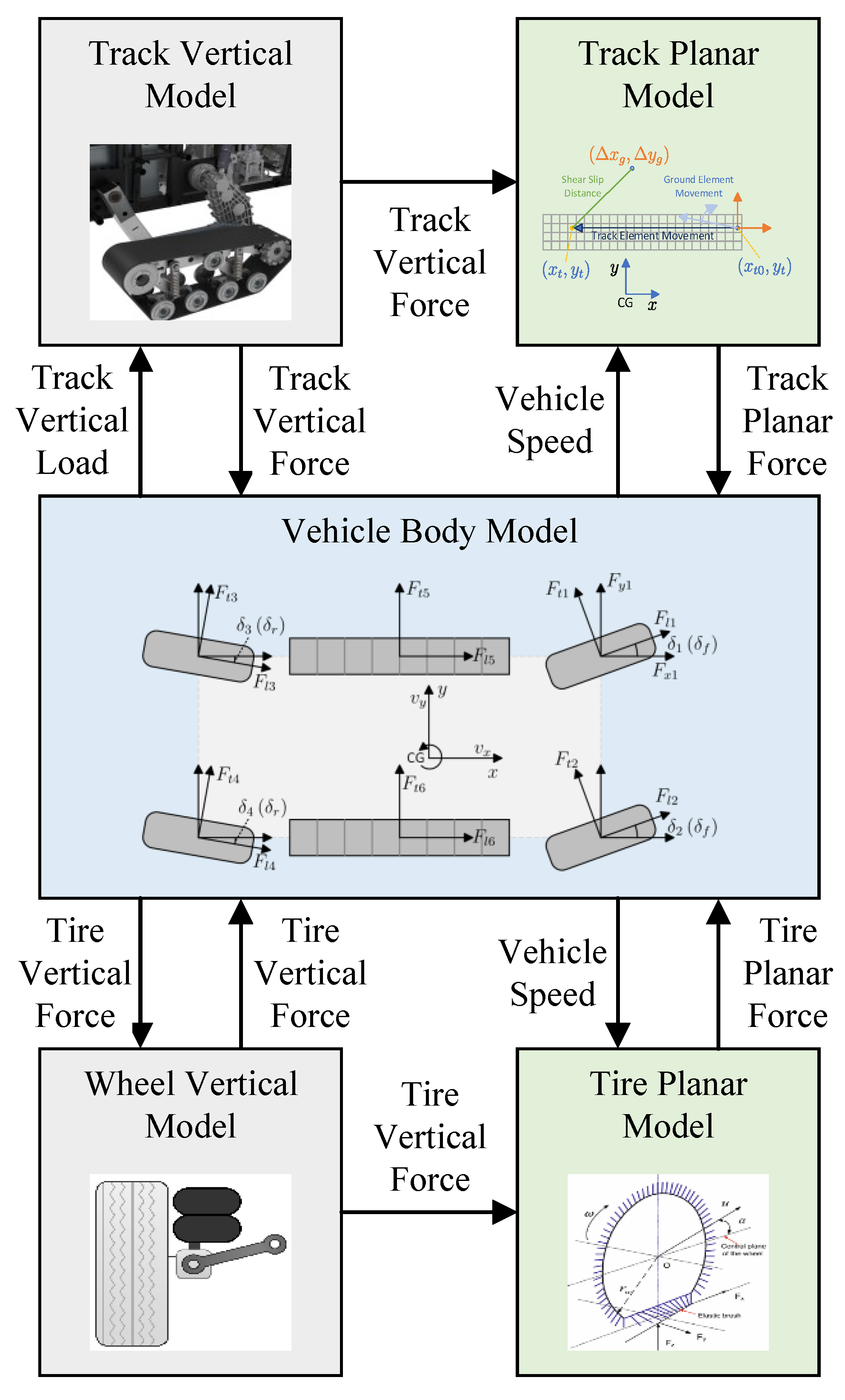
The vehicle model is divided into the following three parts, as shown in
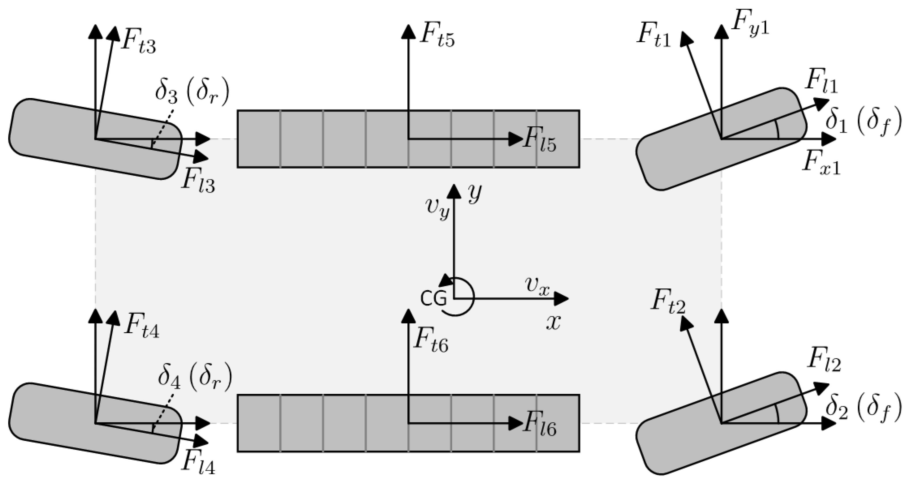
Figure 1: a wheel model to determine the forces generated by the wheels for a given vehicle speed and wheel speed; a track model to determine the forces generated by the track for a given vehicle speed and track speed; and a vehicle body model, which is used to determine how the vehicle moves under the forces generated by the wheels and tracks. The speed change of the vehicle body is determined by the force applied to the vehicle body. The force is generated by the wheel model and track model, and the movement of the vehicle body affects the force generated by the wheels and tracks. Thus, three parts are merged into one model for the controller design.
2.1. Vehicle Body Dynamics
In this section, a model of a wheel–track hybrid vehicle is established. The model is based on a 3-DOF dual-track vehicle model and incorporates a track model. The innovation of this modeling approach stems from its consideration of the nonlinearity in tracks, enhancing their fidelity to real-world conditions. This approach adeptly linearizes these complexities, enabling effective utilization of linear controllers. Moreover, it facilitates seamless integration with models of wheeled vehicles, offering a unified framework for comprehensive dynamic control strategies.
A 3-DOF dual-track vehicle body planar model with an extension of the track drive system is used in this work. The reasons are summarized as follows.
The vehicle is assumed to be driving on flat ground. The ground on which the vehicle operates is assumed to be consistent everywhere; therefore, the ground parameters can be considered constants. Furthermore, the difference in ground level is not high enough to cause the vehicle to considerably roll and pitch. Thus, only a planar model is needed in this work.
The four wheels of the vehicle are driven separately by electric motors with a rotational speed sensor. The torque can also be described by the electric motor model with a current sensor. A single-track vehicle model cannot take full advantage of information about the drive system, including each wheel’s rotational speed and motor torque. The two tracks are independently driven by electric motors. Differential steering is an important feature of the track-driving system. To avoid the limitation in modeling capacity caused by the merging of left and right wheels or tracks, a dual-track model is adopted.
Lateral control of the vehicle is considered to be the major point in this controller. Taking longitudinal velocity into consideration makes the model difficult to linearize. In this paper, longitudinal velocity is considered to be known and controlled by another simple controller rather than MPC [
19]. Thus, the state of the vehicle body is selected as
where
denotes the lateral velocity and
r denotes the yaw rate. In this model, the coordinate system is selected to be an ISO (International Organization for Standardization) 8855 coordinate system where the positive lateral direction is left and the positive yaw direction is anticlockwise, as shown in
Figure 2.
The vehicle body dynamics equation can be described as
which leads to
where
m denotes the mass of the vehicle;
denotes the yaw inertia of the vehicle;
and
denote the longitudinal and lateral position of the wheel or track along the vehicle, respectively;
,
, and
denote the longitudinal force, lateral force, and yaw moment exerted by the ground against the wheel or the track, respectively; and
represents the left and right front-wheel axle for
, left and right rear-wheel axle for
, and left and right middle-track axle for
. The positions of wheels and tracks are at their geometric centers. Positions are measured from the center of gravity of the vehicle so that the displacement of the center of gravity of the vehicle from the center of geometry is considered in this model.
The vehicle model can be described as
where
represents the influence of centripetal acceleration on the lateral velocity of the vehicle;
represents the influence of the wheel on the velocity of the vehicle body; and
represents the influence of track force on the vehicle body, where
In the vehicle body model, the forces of wheels and tracks are along the longitudinal and lateral directions of the vehicle body coordinate system. However, the tire model and track model are calculated along the wheel coordinate system. Thus, a mapping matrix (
) is used to translate forces in the wheel coordinate system as follows:
where
denotes the steer angle of the wheel, and
for four wheels. Thus, forces can be translated from the wheel coordinate system to the vehicle coordinate system as follows:
where
where
and
denote the longitudinal and lateral forces of
ith wheel in their own coordinate systems, respectively. Thus, the force of the wheel can be expressed as
where
where blockdiag denotes diagonal matrix generation. It might be worth mentioning that tracks have no steering system, so there is no need to translate the force coordinate system.
2.2. Tire Model
In order to meet the computational speed requirements of MPC, it is necessary to linearize the model [
18]. A simplified tire brush model is used here. This model allows for easy calculation of the tire’s behavior and response to different inputs [
19]. When the slip angle is equal to or less than the max slip angle, the cornering force (
) can be expressed as a cubic function as follows:
where
denotes the side-slip angle of the
ith tire, which can be calculated based on vehicle speed and geometry;
denotes lateral tire stiffness;
denotes tire friction coefficients;
denotes the vertical force; and
denotes a ratio showing the relationship between the sliding friction coefficient and peak coefficient. It is important to note that
represents four wheels, as is the case with other symbols with
i subscripts in this section. In the next section, different calculations with the same symbol are used but representing two tracks, which can be linearized as
where
denotes the side-slip angle of the tire operating point,
denotes the local lateral tire stiffness, and
denotes the lateral force at the tire operating point. In this paper, the side-slip angle is considered to be approximate at small angles, so the side-slip angle can be expressed as
Thus, lateral tire force can be expressed as
where
and the longitudinal force can be expressed as
where
denotes the driving torque applied on
ith driver.
According to Equations (
13) and (
14), the longitudinal and lateral force of the tire can be expressed as
where
Thus, the force of the wheel system can be expressed as
where
Wheel dynamics can be expressed as
where
Thus, the wheel can be seen as a state-space system with a single state, which is
and the time derivative of the state is
where
According to Equation (
19), the combined wheel state-space system can be expressed as
where
2.3. Track Model
The general theoretical model of tracks [
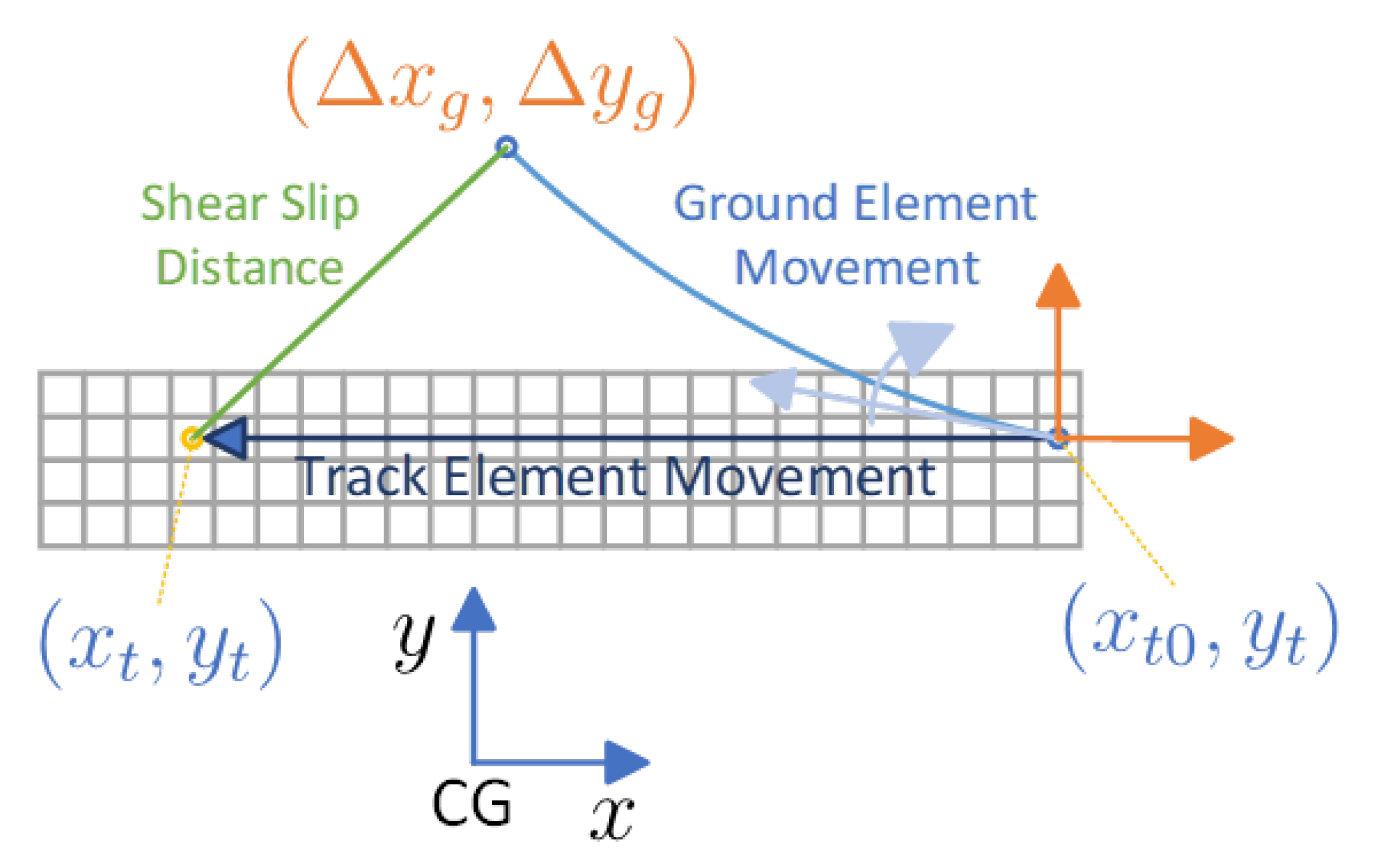
6] is used in this paper. In the general theory, when one part of the track touches the ground, it begins to slip along the ground. The shear pressure is uniform across all areas of each part. The slip distance of one part determines the shear pressure of this part, as shown in
Figure 3.
If the track drive direction moves the vehicle forward, each part touches the ground at the head of the track and moves along the longitudinal direction of the vehicle body. We use a central point on the part to represent the whole part, which is called the track point. The first time the part touches the ground, the point on the ground that coincides with this part is called the ground point. With the movement of the vehicle and the track, the ground point and the track point separate. The distance between the ground point and the track point is the slip distance.
The velocity along the X and Y axes changes over time if calculated in the ground coordinate, making it difficult to derive/obtain the slip distance. To simplify calculation, the vehicle coordinate is used here. The slip distance is independent of the coordinate system. In the vehicle coordinate system, the point on the track is moving along the longitudinal direction of the vehicle. Longitudinal and lateral velocity of the vehicle under a quasi-steady state are assumed to be constant during the time the point when the track moves from the head of the track to its current position. Therefore, the trajectory of the vehicle is an arc on the ground, as shown in
Figure 3. Based on the symmetry of motion, the ground point also moves in an arc in the vehicle coordinate system, and the speed is opposite to the velocity of the vehicle.
The initial speed of the ground point can be expressed as
where
and
denote the initial and lateral velocity of the ground point in the vehicle coordinate system, respectively;
and
denote the initial longitudinal and lateral position of ground point, respectively, which is at the head of the track when the ground point and track point touch; and
and
denote the longitudinal and lateral position of the track point, respectively. For each point on the track, the initial position can be expressed as
where
is the longitudinal position of the track’s front ground edge in the vehicle coordinate system. This represents each part of the track starting to touch the ground at the head of the track. Thus, the movement of the ground point in the vehicle coordinate system is
where
and
denote the longitudinal and lateralmovement of the ground point in the vehicle coordinate system, respectively, and
t denotes the time the ground point moves, which can be expressed as
where
denotes the radius of the track-driving wheel,
denotes the rotational speed of the track-driving wheel, and
denotes the left and right track on the middle axle, which is the same case for other symbols with
i subscripts in this subsection. Thus, the longitudinal and lateral shear movement (
and
, respectively) of the track point is
and the total shear movement (
j) is
Thus, the shear stress at each point can be expressed as
where
K denotes the shear deformation modulus, and
is the max shear force, which can be expressed as
where
denotes the friction coefficient of the track, and
denotes the vertical stress of the track. The direction of the shear force on each part is opposite to the motion of the part. The longitudinal and lateral shear stress can be expressed as
where
and
denote the longitudinal and lateral speed of the track sliding on the ground in the vehicle coordinate system, respectively, which can be expressed as
Thus, the longitudinal and lateral forces of a track (
and
, respectively) are
where
,
,
, and
denote the front-, rear-, left-, and right-edge longitudinal coordinate of the left and right track. The upper and lower limits defined in this way ensure that the positive and negative results of the integration are correct.
We can see that
,
, and
are determined by
and
, which are further determined by
,
r, and
. Thus,
,
, and
can be seen as a function whose input is
,
r, and
. Thus, this model can be linearized as
where
,
, and
are the same as
. Thus, the force generated by the track can be expressed as
where
where it is noticeable that
denotes the rotational speed of the track-driving wheel. Although the symbol is the same, it denotes different states of different driving components than in
Section 2.2. Thus, the force generated by the track can be expressed as
where
The main difference between tracks and wheels is that the driving force can be transmitted to the wheel directly but with friction in the procedure of driving the track. Therefore, in the previous wheel dynamics equation, the only two torques applied to the wheel are the force from the ground and the motor torque, whereas in the dynamics of tracks, the friction must be considered. The dynamics equation of tracks can be expressed as
where
denotes the equivalent inertia of the track-driving wheel, taking the track into consideration;
denotes the torque of the track-driving wheel’s motor; and
denotes the friction of the track, which is considered to be constant. The input of the track is similar to that of the wheels.
Thus, the track dynamics equation can be expressed as
where
Thus, the dynamics equation of the track can be expressed as
where
2.4. Merged Model
In order to implement the controller, the system needs to be merged into one model. The state vector is the combination of the body state, wheel state, and track state.
By subtitling Equations (
16) and (
44) into Equation (
6), i.e., the state equations of each part of the vehicle, the integrated model can be expressed as
where
I is the identity matrix for later discretization. Other matrices in Equation (
49) can be expressed as
3. AMPC Controller Design
The composite drive vehicle has multiple actuators and controllable parameters, with a total of eight inputs, all of which are coupled with each other and mutually influenced. There are also multiple optimization objectives for the controller. Therefore, to comprehensively control these input parameters and consider the performance indicators of vehicle control, model predictive control is adopted to optimize the inputs and achieve the desired vehicle performance.
In this section, we introduce an adaptive model predictive controller (AMPC) designed to address the dynamic and uncertain nature of a wheel–track vehicle. Unlike traditional controllers, the AMPC offers distinct advantages in terms of its ability to autonomously adjust to changing operating conditions, thereby optimizing system performance and robustness. Through rigorous analysis and simulations, we demonstrate that the AMPC not only improves control accuracy and stability but also enhances resilience against disturbances. By explicitly incorporating adaptive mechanisms, our approach provides a practical solution for achieving superior control performance in the control of a wheel–track vehicle, ensuring reliable operation under varying environmental and operational conditions.
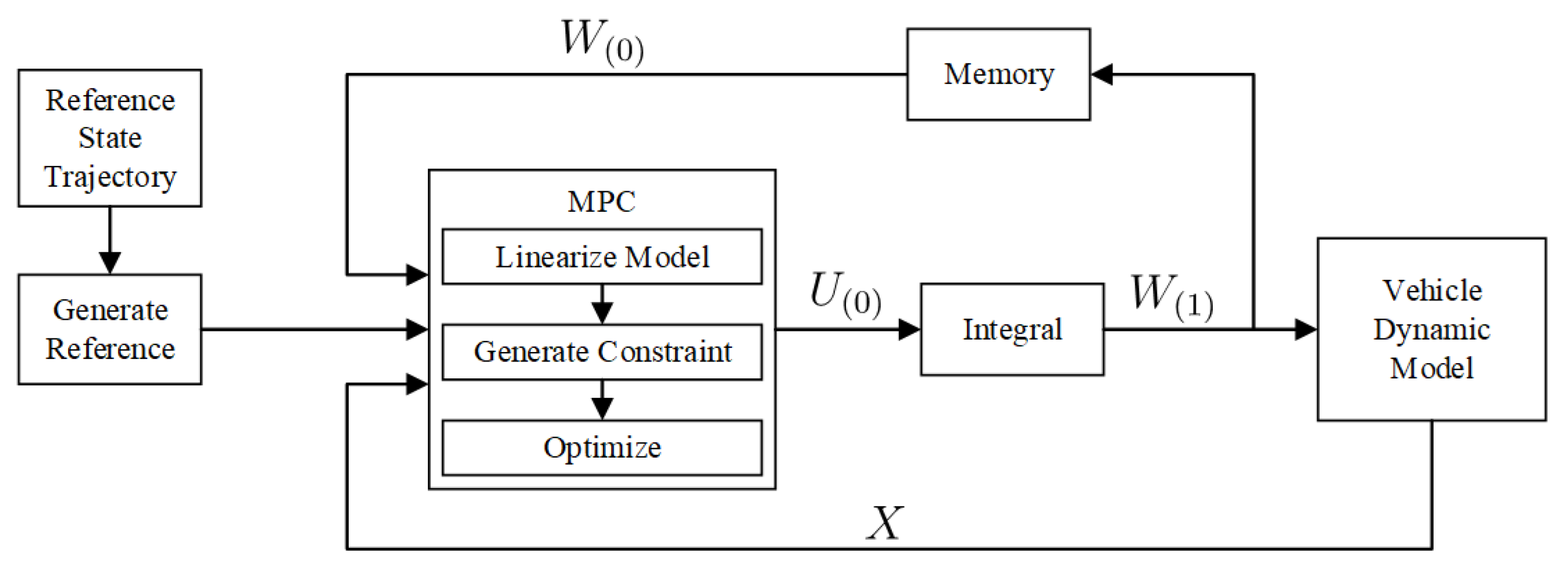
In order to achieve real-time control of the vehicle, a complex nonlinear optimization algorithm is avoided in the controller design. Instead, all optimization objectives are transformed into quadratic forms. For the controller, after obtaining all the control objectives, it only needs to perform one quadratic optimization to obtain the optimal control. The controller has the form shown in
Figure 4.
3.1. Control Objects
In vehicle control, to achieve better control performance, the desired control effect can be translated into key objectives that correspond to improved vehicle handling, enhanced vehicle stability, prevention of tire and track slippage, and other control effects. These objectives are carefully selected and transformed into cost functions in MPC, allowing MPC to perform subsequent optimization to obtain control results that meet the objectives.
3.1.1. Improved Vehicle Handling
Vehicle handling performance can be manifested as the performance in tracking the desired yaw rate. Thus, the veracity and response time can have a great influence on the experience of the driver, which is the handling performance. The tracking performance can also contribute to autonomous driving; in many practical controls, like path tracking, the structure of the hierarchical controller contains a high-level target yaw-rate generator and a low-level vehicle dynamics controller that follow the desired yaw rate. The ability to follow the desired yaw rate accurately and rapidly is important in these situations. Thus, this control object can be satisfied by eliminating the yaw rate error (
), which can be expressed as
where
denotes the desired yaw rate.
3.1.2. Slip Control
In vehicle control, to prevent excessive tire slip, which can reduce vehicle stability and increase tire wear, it is necessary to limit the slip ratio. The slip ratio of the tire can be calculated from the vehicle speed and tire rotation speed, and by utilizing the vehicle model, the slip ratio of the tire under given inputs can be predicted. The input is then maintained within a range that keeps the tire slip ratio within an acceptable range.
The slip ratio of the
ith driving component can be expressed as
The greater the discrepancy between the wheel speed and the vehicle speed, the higher the slip rate and the greater the instability of the vehicle. Hence, the desired wheel speed is the vehicle speed in the absence of slip.
By increasing the weight of the tire speed control, the effect of controlling the vehicle’s slip rate can also be achieved. Most of the time, with a suitable weight coefficient setting, the tire slip rate can be directly controlled within an allowable range. The controller only needs to solve an unconstrained extreme value problem, which can reduce the computational load of the controller and improve its real-time performance. Only when the predicted slip rate is too high does the controller rework the solution to the optimization problem with constraints.
3.1.3. Improved Lateral Stability
Vehicle lateral stability can be obtained by keeping the vehicle’s side-slip angle within a predetermined range. The utilization of a consistent threshold on the side-slip angle to ensure lateral stability has been a prevalent practice. Recent research has used constraints limiting the side-slip angle of rear tires because the drift of the rear tires will cause a larger yaw rate and decrease the lateral stability of the vehicle [
18]. Unlike pure wheeled vehicles, wheel–track hybrid vehicles can rely on the track system to enhance lateral stability. Therefore, the connection between the rear tire’s side-slip angle and lateral stability is not so distinct, and using the side-slip angle of the vehicle is more appropriate here. Thus, the side-slip angle (
) used here can be expressed as
In model predictive control of vehicles, to enhance lateral stability, the desired lateral velocity is set to zero. If the weight of the desired lateral velocity is greater than zero, the optimizer considers the lateral velocity in generating the model inputs for optimization. Additionally, the optimizer constrains the lateral velocity within certain limits.
3.2. Adaptive Model Predictive Controller Design
The use of MPC requires the discretization of the overall model due to the fact that the controller can only optimize the input in a finite number of steps. The discretization process involves transforming the continuous model into a discontinuous model with a certain time step, allowing the controller to operate on each step individually. The discretized model is then used by the controller to predict and optimize the system behavior over a finite time horizon.
When discretizing a continuous system, matrices
A,
B, and
I need to be horizontally concatenated into a large matrix (
S), and zeros need to be added below it to make
S a square matrix.
The whole matrix can be seen as the state matrix of the extended system, where input is seen as the external state. Thus, the discretized state matrix can be expressed as
where
is the time interval of one step, and expm denotes the matrix exponential function, which is integrated in MATLAB R2024a. Thus, the original matrices (
A,
B, and
I) correspond the following positions in the discretized matrix:
where
,
, and
denote the discretized
A,
B, and
I, respectively. The bias input (
W) and bias state differential (
D) are considered to be invariable during the control horizon and are replaced by the constants
and
, respectively. Thus, the discretized system can be expressed as
where
is the state at the
kth step of time, as is the case for other symbols. Thus, the predicted state of the system from the 1st to
Nth step of time can be expressed as
where
where repmat is the repeat matrix function;
denotes vertical repetition of the column vector (
)
N times; and
,
, and
denote the accumulated state matrix and input matrix of
U,
and
, respectively. The matrices in Equation (
59) can be expressed as
where
I denotes the identity matrix with the proper size to match the rule of matrix multiplication.
The fundamental principle of an MPC controller is to create a cost function and seek the extreme value of the cost function. To make the controller applicable to real-time systems, the entire cost function is expressed as a quadratic function. The model is used in MPC to predict the future behavior of the system and optimize the current control action by considering future consequences. The output of the controller, which is also the input of the system, is generated by calculating the optimized control, which can produce the minimum cost. The cost function plays a crucial role in MPC. as it quantifies the performance criterion, which can be any combination of system states and inputs. There are two main control objects. One is to control the state of the system to expectation. The other is to eliminate the input of the system, which is also the output of the controller. Thus, the cost function can be expressed as
where
denotes the desired state at steps 1 to N. The Yaw rate of the desired state is generated from the desired yaw trajectory using interpolation; desired
is 0, and the desired driver state is calculated based on the desired longitudinal velocity of the vehicle, considering no wheel slip. The MPC problem can be expressed as
where
The optimization problem solved at each time step aims to minimize the cost function over a prediction horizon while satisfying any constraints on the system inputs and outputs. The optimized control action obtained from the solution of the optimization problem is implemented in the system, and the process continues iteratively over time. The quadratic form of the cost function arises from expressing it as a weighted sum of squared errors between the predicted and actual system outputs. By minimizing this quadratic cost function, MPC effectively minimizes the squared errors between the predicted and actual outputs, resulting in improved system performance.
4. Validation
To validate the controller’s performance, a simulation is conducted. The structure of the simulation model is shown in
Figure 5. A vehicle body model from the MATLAB Vehicle Dynamics Blockset is utilized, and a track module is implemented using the dynamic model of the steering model for a tracked vehicle. The reliability of this track model has been validated in comparison with RecurDyn. A combined slip-tire model block in SIMULINK 8.5 is used in the simulation. The controller is developed using MATLAB and SIMULINK and connected to the model.
Due to its mechanical structure, the tracks demonstrate stronger ground-holding capabilities than tires on low-friction road surfaces. Therefore, a higher friction coefficient is assigned to tracks compared to tires. The wheel–track hybrid mechanism is designed to enhance performance on the ground with a low to medium friction coefficient at low speed. The simulation is conducted using the parameters listed in
Table 1.
The controller is validated in a dual J-turn scenario, as shown in
Figure 6. The target vehicle’s speed is constant at 18 km/h. In the simulation, it is observed that the longitudinal velocity cannot be controlled only using the target wheel- and track-driving speeds. Therefore, another simple PID controller is used to maintain the longitudinal speed of the vehicle within a reasonable range.
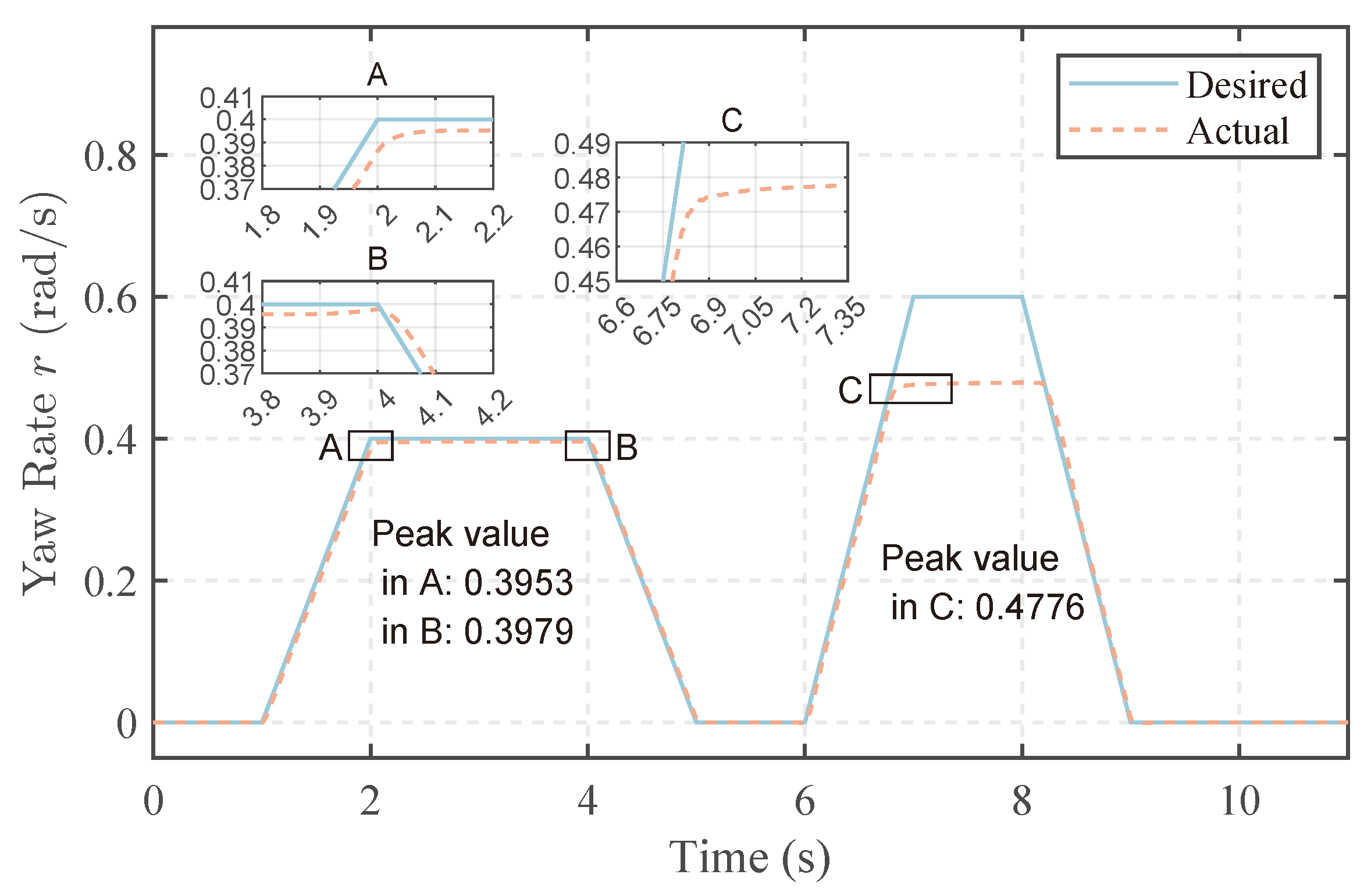
In the first J turn, the desired yaw rate increases uniformly with angular acceleration of 0.4 rad/s2 in the time interval of [1 s, 2 s], corresponding to the entry phase of the J-turn maneuver. It then remains constant for 2 s, corresponding to the in-turn phase. The yaw rate then decreases uniformly with angular acceleration of −0.4 rad/s2 for 1 s, corresponding to the exit phase of the maneuver. The second J turn is similar to the first J turn but with a larger angular acceleration of 0.6 rad/s2 and a shorter time spent at the max yaw rate of 0.6 rad/s.
The desired and actual yaw rates are shown in
Figure 6. In the first J turn, the vehicle’s yaw rate is controlled within the expected range. However, in the second J turn, the vehicle fails to achieve a higher yaw rate. At the conclusion of the entry phase in the first J turn, the vehicle reaches a maximum yaw rate of 0.395 rad/s, after which the yaw rate stabilizes. During the exit phase, there is a slight increase in the vehicle’s yaw rate, with the highest value reaching 0.398 rad/s. Subfigures A, B, C, and D in
Figure 6 suggest that this phenomenon may be attributed to a slight increase in the differential torque between the wheels and tracks under the given conditions. In the second J turn, the desired yaw rate reaches a larger value of 0.6 rad/s within the same entry time. However, the vehicle’s yaw rate fails to reach the desired value, peaking at 0.478 rad/s during the turn. There is no significant increase in angular velocity approaching the exit phase [8 s, 9 s], and considering subsequent torque diagrams, it becomes evident that the differential torque is already substantial compared to the first J turn. Further increases could risk destabilizing the vehicle, preventing the attainment of the desired yaw rate.
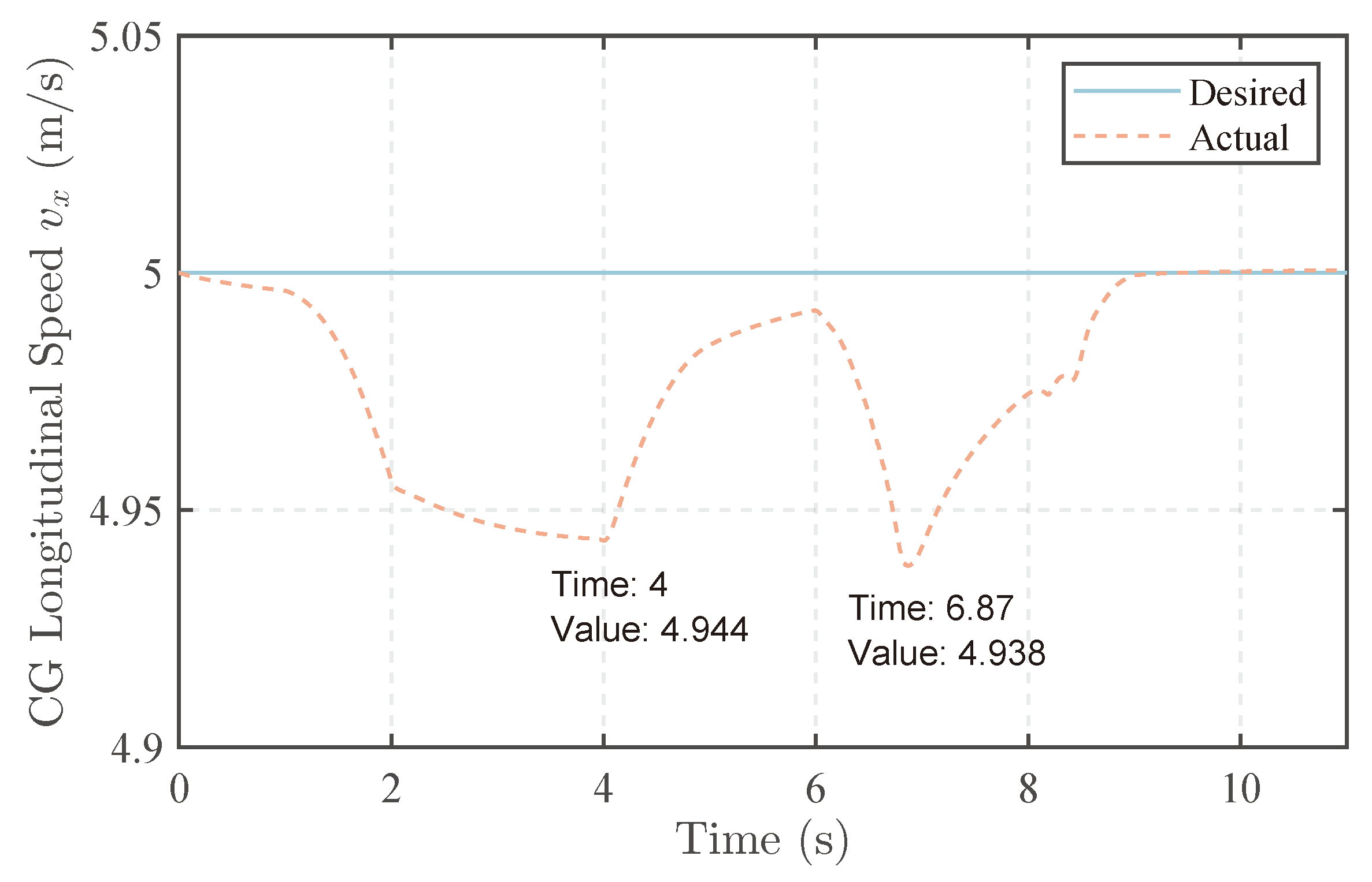
The longitudinal speed of the vehicle is shown in
Figure 7. In the first J turn, as depicted in the graph, the vehicle gradually enters the curve, and the vehicle’s angular velocity increases, while the longitudinal velocity decreases. Even before the vehicle’s speed stabilizes, it has already entered the exit phase, with the lowest speed occurring at 4 s. This point marks the transition from the curve to the straight path, with a minimum speed of 4.944 m/s. Subsequently, the vehicle’s longitudinal speed starts to rise again. Although further adjustments to the proportional and integral gains could expedite the attainment of the desired longitudinal velocity, it would also make the controller more prone to overshooting. It can be inferred that the reduction in speed is attributed to the wheels experiencing a turning angle, diminishing the driving force generated by the wheels in the longitudinal direction. Additionally, at this moment, the driving force produced by the tracks is also reduced compared to the scenario where the yaw rate is zero. Simultaneously, the lateral force of the wheels has a backward component in the vehicle’s longitudinal direction, contributing to the decrease in vehicle speed. In the second J turn, due to a larger lateral angular velocity, the minimum longitudinal speed is lower. It is worth noting that the speed does not continue to decrease in the turn. Because the controller output is the derivative of the system input, there is not enough torque available at the entry to sustain the longitudinal speed. In the turn, there is no need for extra torque to increase the yaw rate, so the longitudinal speed of the vehicle begins to approach the desired value.
The front and rear steering angles in this scenario are shown in
Figure 8. A similar front and rear steering angle is observed. Front and rear steering angles have different signs for their opposite contributions to the yaw rate of the vehicle. The steering angle is likely to maintain a linear relation with the desired yaw rate, even taking the nonlinear character of wheels and tracks into consideration. The front and rear wheel angles are not identical. At the end of the entry phase (4 s), the rear wheel angle decreases slightly, while the front wheel angle increases slightly. By analyzing the torque curves of the wheels and tracks, it can be inferred that this phenomenon corresponds to the upcoming sudden change in yaw moment at the end of the entry phase. Therefore, the controller intervenes more with the differential torque steering of the drive mechanism and increases the proportion of the front wheels in steering to cope with the subsequent sudden change in vehicle yaw moment. In the second J turn, to enhance vehicle stability, the controller reduced the steering angle of the rear wheels.
The driving torques of wheels are shown in
Figure 9. They maintain an upward trend when the desired yaw rate increases and stop rising when the vehicle’s yaw rate reaches the desired value. At the same time, the controller makes performs optimization to obtain a certain differential torque that should be applied by the wheels to achieve steering. The torques of the front and rear wheels on the same side are essentially the same, indicating that the effects of front and rear wheel torques on the body are essentially the same under the current model, leading to a similar torque distribution using the current optimizer. Upon entering a curve, both the front and rear wheels exhibit peak torque, as shown in subfigures A and B, aligning with the vehicle’s dynamics. First, there is a discontinuity in the first derivative of the vehicle’s desired yaw rate corresponding to the desired yaw acceleration, resulting in a discontinuity in the expected torque. Secondly, as the vehicle’s yaw rate increases, a higher driving torque is required, yet when the desired angular velocity remains constant, the vehicle no longer necessitates this excess driving torque. Consequently, an abrupt decrease in wheel driving torque is observed. In the second J turn, a larger differential torque is generated by the wheels, increasing their significance in steering the vehicle. At 6.8 s, further increasing the yaw rate by steering becomes challenging without compromising vehicle stability. Therefore, the controller opts for a larger differential torque.
The driving torque of tracks is shown in
Figure 10. The torque behavior of the tracked drive is similar to that of wheels, but tracks can only steer using differential speed. Consequently, the differential torque of tracks becomes more pronounced.
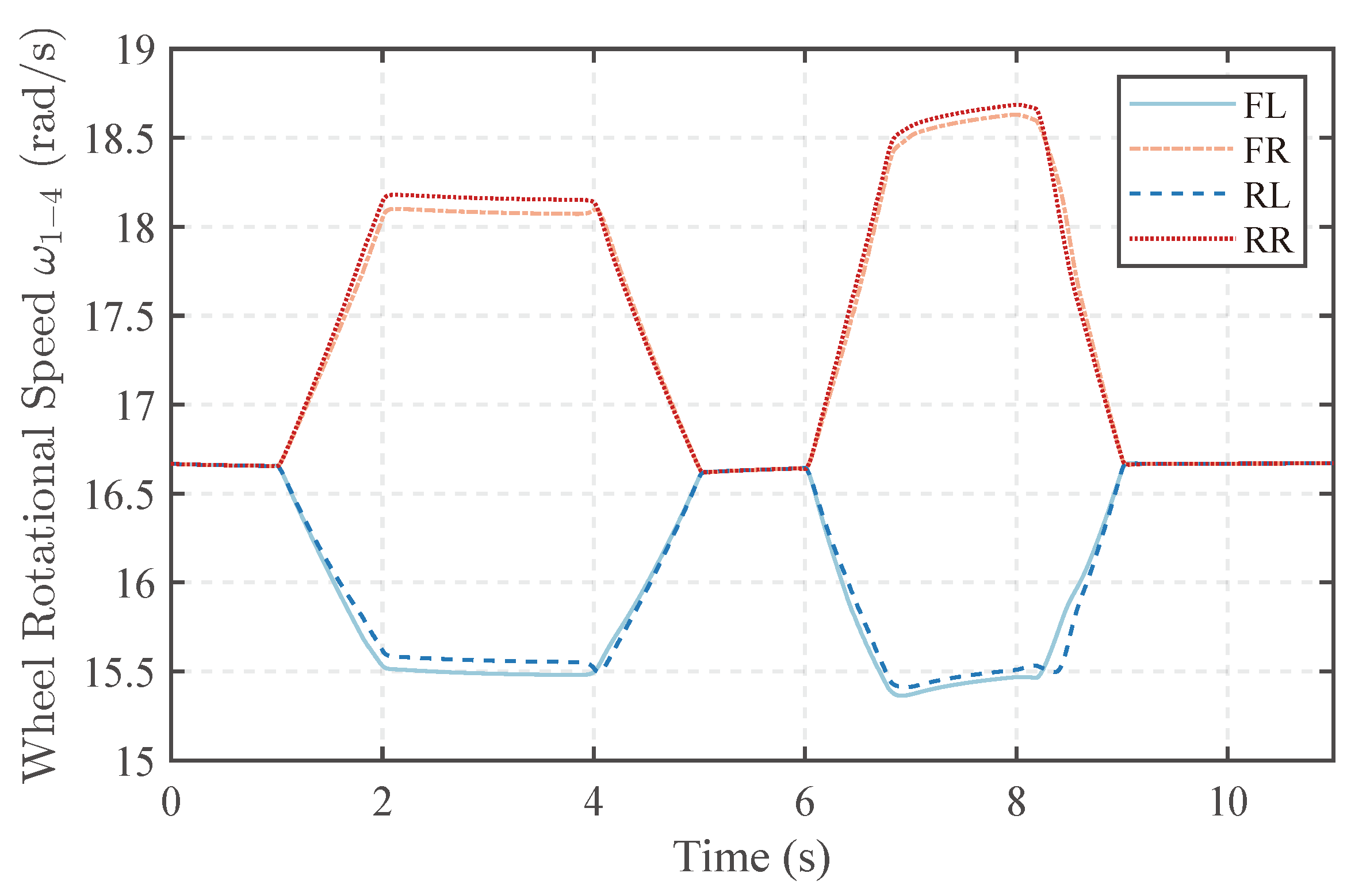
The rotational speed of the wheels is shown in
Figure 11. The rotational speed of the tracks is shown in
Figure 12. The rotational speeds of wheels and tracks are similar to the ideal scenario. The outer drive speed exceeds the inner drive speed. Simultaneously, to generate the same differential torque, the difference between the outer drive speed and the ideal speed is greater than that of the inner drive. This is determined by the nature of slip ratios.
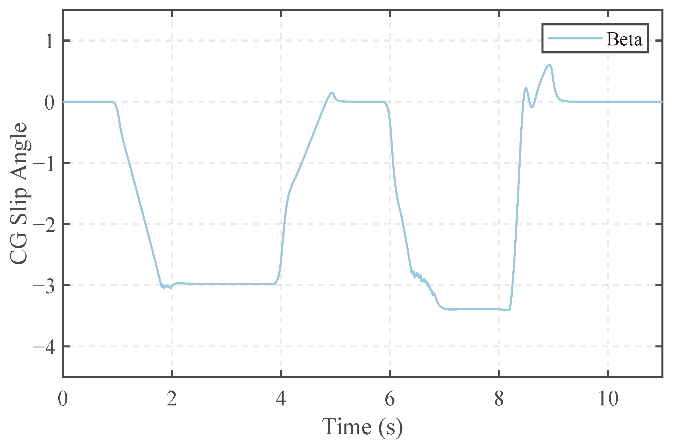
The side-slip angle of vehicle CG is shown in
Figure 13. In the second J turn, the lateral speed is controlled within the desired range. At 6.4 s, because the controller’s control domain reaches the side-slip angle limit, side-slip angle acceleration begins to decrease, maintaining stability throughout the turn and never exceeding 3.4°.

