Article

The Development and Nonlinear Adaptive Robust Control of the Air Chamber Pressure Regulation System of a Slurry Pressure Balance Shield Tunneling Machine

by
Shuai Wang
,
Yakun Zhang
*,
Guofang Gong
and
Huayong Yang
The State Key Laboratory of Fluid Power & Mechatronic Systems, Zhejiang University, Hangzhou 310058, China
*
Author to whom correspondence should be addressed.
Machines 2024, 12(7), 457; https://doi.org/10.3390/machines12070457
Submission received: 30 May 2024 / Revised: 30 June 2024 / Accepted: 3 July 2024 / Published: 4 July 2024
(This article belongs to the Section Automation and Control Systems)

Abstract

:
The rapid and accurate control of air chamber pressure in slurry pressure balance (SPB) shield tunneling machines is crucial for establishing the balance between slurry pressure and soil and water pressure, ensuring the stability of the support face. A novel air chamber pressure control method based on nonlinear adaptive robust control (ARC) and using a pneumatic proportional three-way pressure-reducing valve is proposed in this paper. Firstly, an electric proportional control system for the air chamber pressure is developed. Secondly, a nonlinear state space model for the air chamber pressure regulation process is established. Utilizing experimental data from the SPB shield tunneling machine test bench, nonlinear adaptive identification is conducted through the nonlinear recursive least square algorithm. The results demonstrate the model’s effectiveness and accuracy. Then, a nonlinear ARC for air chamber pressure is designed based on the backstepping method, and its Lyapunov stability is proved. Finally, the feasibility and effectiveness of the controller designed in this paper is verified through simulation and experiments. The results demonstrate that the developed control system can compensate for the nonlinearity and disturbance in the air chamber pressure regulation process. It can achieve good transient and steady-state performance and has good robustness against uncertainty.

1. Introduction

Slurry pressure balance (SPB) shield tunneling machines are widely used in the construction of underground tunnels due to their high excavation efficiency and superior construction quality. Their excellent support capabilities and adaptability to various strata make them especially suitable for high-permeability and low-viscosity ground conditions, such as those found in cross-river and undersea tunnels. SPB control is a key technology of the machine because it directly relates to the safety of tunnel construction and ground settlement. In recent years, autonomous SPB control has emerged as a significant development trend due to the limitations of manual operation, including the lack of effective geological information between exploration boreholes and the subjectivity inherent in manual operation processes. High precision and adaptive control of the air chamber pressure are at the very heart of autonomous SPB control. Ideally, the air chamber pressure should be adjusted continuously in response to changes in formation pressure. However, current engineering practices still predominantly use purely mechanical air chamber control systems. These systems struggle to meet the requirements of autonomous SPB control, such as the need for adaptation, robustness to disturbances, and the ability to handle model nonlinearity and uncertainty. As a result, many researchers are studying these mechanisms and developing autonomous control methods for air chamber pressure to overcome these challenges.
Regarding the mechanisms of air chamber pressure regulation, Shen et al. [1] examined the impact of fault fracture zones and introduced the concept of the formation influence coefficient. This coefficient serves as an input to prediction models utilizing various machine learning algorithms to forecast slurry pressure. They also analyzed how the distribution of the formation influence coefficient and the width of the fracture zone affect the accuracy of slurry pressure predictions. Xu et al. [2] used several machine learning algorithms to predict the geological conditions in super-large-diameter SPB shield tunnels. Liu et al. [3] used the finite difference software FLAC 3D to study the global sensitivity of the influencing factors of the slurry shield excavation face based on the orthogonal test principle. Zizka et al. [4] investigated the impact of transient slurry penetration on support pressure transfer during cyclic soil excavation at the tunnel face. They characterized how different combinations of slurry penetration and excavation scales affect the efficiency of tunnel face support and pressure transfer. Wang et al. [5] used Long Short-Term Memory (LSTM), variational mode decomposition, detrended fluctuation analysis, and cross-correlation analysis to predict the shield tunneling machine slurry pressure in mixed ground conditions. Shen et al. [6] developed a high-water-pressure (2.0 MPa) SPB shield tunneling machine model test platform and addressed the problem of achieving slurry circulation in the scaled test platform. Liu et al. [7] established the upper and lower limits of slurry support pressure based on theories of slurry splitting (infiltration failure) and silo theory. They then analyzed the characteristics of the support pressure range (adjustable range) by considering factors such as static water pressure, soil properties, shield tunnel diameters, and soil cover thickness. QI et al. [8] developed a simulation test system for SPB shield tunneling and analyzed the space–time variation laws of ground surface settlements and the slurry membrane morphology during shield excavation. Liu et al. [9] studied the development mode and stress situation of the active failure of excavation faces in two strata under different water head heights. Wei et al. [10] designed an apparatus for the penetration of slurry and performed some experimental studies on the balance law between slurry pressure and effective stress in a slurry shield. Song et al. [11] analyzed the dynamic characteristics of the air chamber in large-diameter slurry shield tunneling machines and developed a mathematical model. They identified the key factors influencing the pressure balance control system at the excavation face, particularly in relation to the effects of pulsating pressure. Li et al. [12] investigated the mechanisms of excavation balance in slurry balance shield tunneling and the distribution patterns of settlement during tunneling. Their study utilized experimental tests on slurry shield models to gain these insights. The air chamber pressure regulation process is a complex, multivariable, coupled, nonlinear system. To simplify modeling and analysis, most existing research employs linear models. However, this simplification obscures the mechanisms of multi-system coupling and leads to non-adaptive control algorithms, resulting in reduced control performance and limited adaptability to variations in the formation of water and soil pressure.
In terms of air chamber pressure control, Zhang et al. [13] proposed a cyber–physical system (CPS)-based hierarchical autonomous control scheme. In this work, the hybrid switched model predictive controller was compared with a deep neural network controller for SPB control. The results showed that the autonomous control system with a switched model predictive controller outperformed that of the deep neural network. Li et al. [14] presented modified Smith predictor-based and disturbance observer-based dynamic sliding mode control (MSP-DSMC, DO-DSMC) systems, respectively, for slurry level regulation and air pressure holding. Li et al. [15] introduced a model predictive control (MPC) system employing a diagonal recurrent neural network and evolved particle swarm optimization for SPB operations. This approach effectively regulates slurry circulation and air pressure holding systems based on geological conditions during construction. Li et al. [16] developed a pressure balance control system for direct-type SPB shield tunneling machines based on predictive function control. They also proposed a method for initializing the controller to address the transition from a manual to automatic mode. Zhou et al. [17] introduced a predictive control system for air chamber pressure in SPB shield tunneling machines using an Elman neural network (ENN) model. They implemented a particle swarm optimization (PSO) algorithm to enhance the learning capability of the ENN model. Song et al. [18] developed a transfer function model for the slurry balance process. They implemented a fuzzy PID controller to maintain a constant air chamber pressure and regulate the slurry flow rate. However, since the slurry pressure still requires manual adjustment, this method only enables semi-automatic control of the SPB process. Previous research has made various contributions to the control of air chamber pressure in SPB shield tunneling machines. However, air chamber pressure is a typical nonlinear dynamic process, and its model is subject to uncertainties and disturbances such as changes in slurry level and formation pressure. Most existing studies have not fully elucidated the multivariable coupling mechanisms involved in regulating air chamber pressure, nor have they adequately compensated for the nonlinearity and uncertainty of the plant model. On the other hand, current engineering systems typically employ mechanical PID controllers for pressure regulation. However, these controllers still require manual adjustment and fail to achieve autonomous control. They exhibit slow response times and low accuracy, making it challenging for them to meet the engineering requirements for control performance.
In order to bridge the gap between the engineering needs and the existing systems in the industry, as well as further advance autonomous SPB control technology, the following new contributions are made in this paper:
(1)
An electric proportional air chamber pressure regulation system is developed using a pneumatic proportional three-way pressure-reducing valve. This system overcomes the shortcomings of traditional pressure regulation systems that use mechanical PID controllers in terms of control performance.
(2)
A nonlinear state space model for the air chamber pressure regulation process is established. A nonlinear adaptive identification is performed based on the experimental data from the SPB shield tunneling machine test bench, verifying the model’s effectiveness and accuracy. This model reveals the mechanism of the air chamber pressure regulation process.
(3)
A nonlinear adaptive robust controller for air chamber pressure is proposed using the backstepping method, with its Lyapunov stability proven. The feasibility and effectiveness of the proposed controller are verified through simulation and experiment.
The remainder of this paper is organized as follows: Section 2 covers the development of the electric proportional control system for air chamber pressure, including the modeling and analysis of the dynamics of the air chamber pressure regulation process, as well as the identification of model unknown parameters. Section 3 is dedicated to the design of a nonlinear controller for air chamber pressure. Section 4 focuses on the simulation verification and experimental verification of the proposed method. Finally, the conclusions are presented in Section 5.

2. Development, Modeling, and Analysis of the Air Chamber Pressure Regulation Process

In this section, an electric proportional control system for air chamber pressure is developed. A nonlinear state space model for air chamber pressure regulation is established, and the mechanism of the air chamber pressure regulation process is analyzed. Online adaptive identification and verification of the model’s undetermined parameters are conducted using experimental data from the SPB shield tunneling machine test bench.

2.1. Development of Air Chamber Pressure Regulation System

The traditional mechanical air chamber pressure regulation system does not meet the requirements for autonomous SPB control. Therefore, this paper develops a pneumatic proportional regulation system for air chamber pressure. This system enables continuous proportional control of the air chamber pressure, minimizing the effects of pressure variations. It also enhances control accuracy, response speed, and supports remote and advanced program control capabilities.
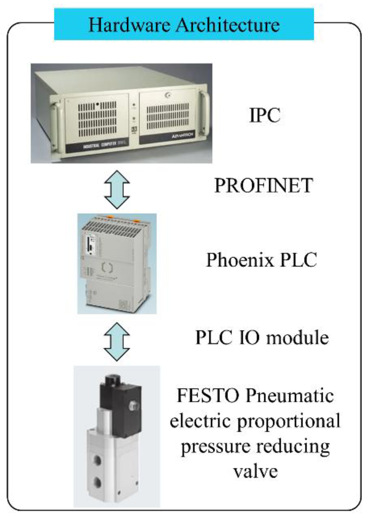
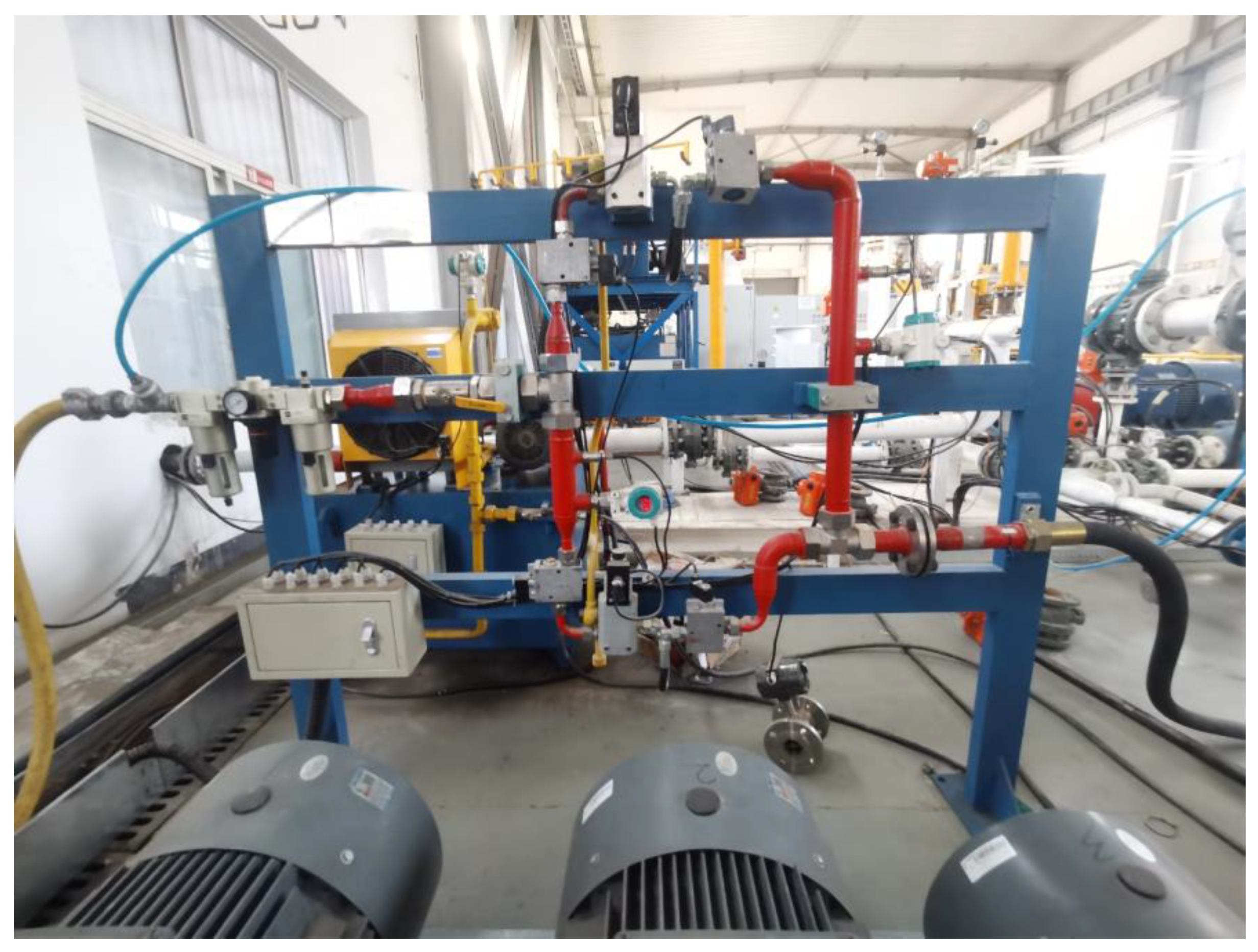
The working principle of the proposed system is depicted in Figure 1. Air chamber pressure is controlled using a pilot-operated, pneumatic, proportional, three-way, pressure-reducing valve. In this setup, a proportional electromagnet adjusts the pressure P 1 in the pilot stage pressure-regulating chamber. The pressure difference between P 1 and the outlet pressure P a of the main valve’s spring chamber at both ends regulates the main valve spool’s opening, thereby controlling the outlet pressure P a of the main valve. The hardware’s architecture is based on the Phoenix PLC and the MPPE-type proportional pressure-regulating valve from FESTO, illustrated in Figure 2 and Figure 3.
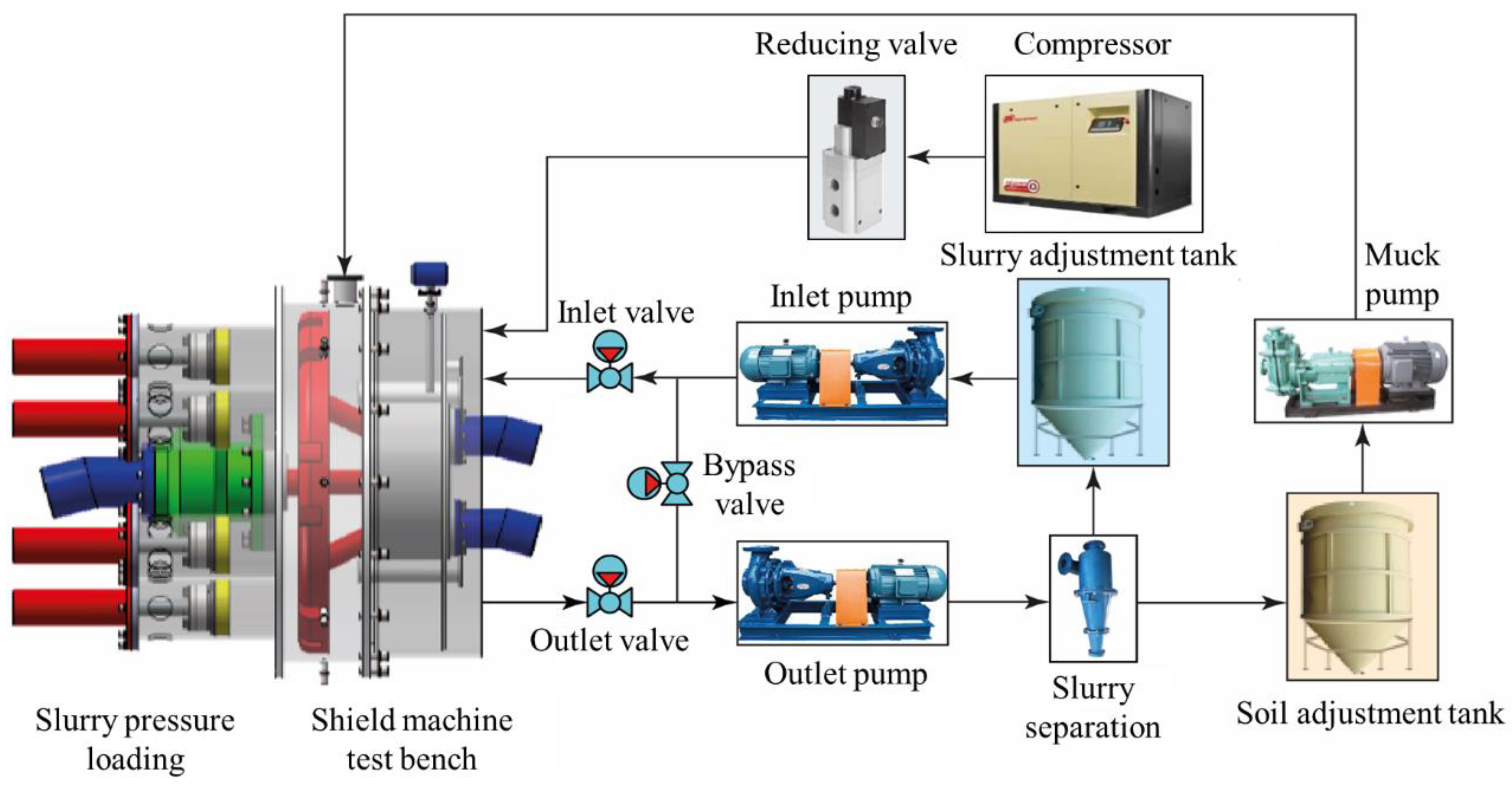
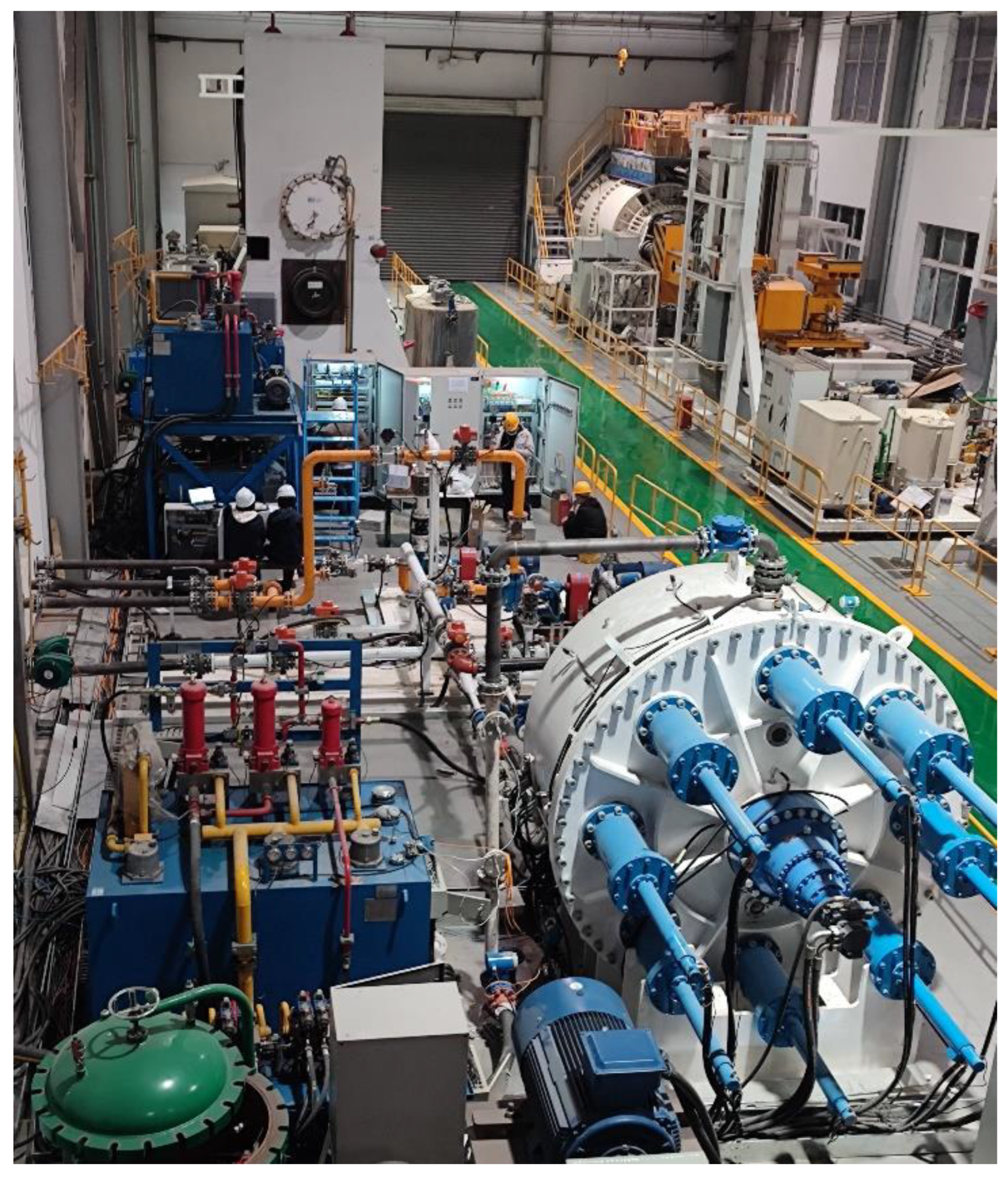
To evaluate the effectiveness of the proposed air chamber pressure control method, we developed a comprehensive simulation approach that replicates environmental disturbances and active control factors in the air chamber pressure regulation process. Subsequently, we designed a closed-loop circuit for SPB control, as illustrated in Figure 4. The air chamber pressure control system, along with the corresponding human–machine interface software, was developed using Simulink and PLCnext Engineer. Additionally, a Ø2.5 m multi-purpose SPB shield machine test bench was constructed, as shown in Figure 5 [19].

2.2. Nonlinear Dynamic State Space Model

Referring to the idealized analytical model of the air chamber pressure regulation process shown in Figure 1, the volume of air within the air chamber is considered the control volume. This is represented by the light blue area in Figure 1. A Cartesian coordinate system is fixed on the SPB shield tunneling machine for reference. The control volume is a circular space, and its infinitesimal area can be expressed as
d A = { 2 ( R 2 z 2 r 2 z 2 ) d z ,   z [ r , r ) 2 R 2 z 2 d z ,   z [ r , R ) [ R , r )
By integrating Equation (1), the volume occupied by compressed air can be expressed as
V a = A w = { w [ π R 2 2 h R 2 h 2 R 2 a s i n ( h R ) ] ,   h [ r , R ) w [ π ( R 2 r 2 ) 2 ( R 2 h 2 r 2 h 2 ) h + r 2 a s i n ( h r ) R 2 a s i n ( h R ) ] ,   h [ r , r ) w [ π ( R 2 2 r 2 ) h R 2 h 2 R 2 a s i n ( h R ) ] ,   h [ R , r )
The time change rate of the volume occupied by compressed air can be expressed by differentiating V a with respect to h :
V ˙ a = { 2 w ( r 2 h 2 R 2 h 2 ) h ˙ ,   h [ r , r ) 2 w R 2 h 2 h ˙ ,   h [ r , R ) [ R , r )
So V a and its differential V ˙ a can be obtained using the slurry-level-sensor measurement value h and its differential h ˙ , according to Equations (2) and (3).
Due to the fact that compressed air is in a high-temperature and low-pressure state relative to its critical point value, it can be assumed to be an ideal gas. The dynamic differential equation for the current in the proportional electromagnetic iron coil in a pilot-operated pneumatic proportional three-way pressure-reducing valve is
I ˙ = R e I K e x ˙ v 1 + U V L
The differential equation for the movement of the pilot valve spool is
x ¨ v 1 = K s 1 x v 1 B v 1 x ˙ v 1 P 1 A v 1 K f 1 x v 1 + F m m v 1
The output force equation of the proportional electromagnet is
F m = K I I K x x v 1
The process of compressed gas passing through the valve port is complex, and it is usually regarded as an isentropic flow of ideal gas through a contracted nozzle. The flow rate formula is given by [20,21]:
m ˙ 1 = C d v 1 P u π d v 1 x v 1 R 1 T u φ ( P d P u )
where
φ ( P d P u ) = { 2 κ κ 1 [ ( P d P u ) 2 κ ( P d P u ) κ + 1 κ ] ,   P d P u ( 0.528 , 1 ] ( 2 κ + 1 ) 1 κ 1 2 κ κ + 1 ,   P d P u ( 0 , 0.528 ]
The gas state equation of the pilot valve is
P 1 V 1 = m 1 R 1 T 1
By differentiating the gas state equation, it can be found that
P ˙ 1 V 1 + P 1 V ˙ 1 = m ˙ 1 R 1 T 1 + m 1 R 1 T ˙ 1
Assuming that the inflow/outflow process of compressed air is adiabatic and there is little change in air temperature, the temperature differential can be simplified to zero. The equation for establishing the outlet pressure of the pilot valve can be obtained as follows:
P ˙ 1 = R 1 T 1 m ˙ 1 P 1 V ˙ 1 V 1
The motion equation of the main valve spool is
x ¨ v 2 = ( K v 2 K v 3 ) x v 2 B v 2 x ˙ v 2 P a A v 3 K f 2 x v 2 + P 1 A v 2 m v 2
The air mass flow rate equation for the main valve port is
m ˙ a = C d v 2 P u π d v 2 x v 2 R a T u φ ( P d P u )
The gas state equation of the main valve is
P a V a = m a R a T a
By differentiating the air state equation, it can be obtained that
P ˙ a V a + P a V ˙ a = m ˙ a R a T a + m a R a T ˙ a
The equation for establishing the pressure at the outlet of the main valve, i.e., the air chamber, can be obtained as follows:
P ˙ a = R a T a m ˙ a P a V ˙ a V a
Due to the operational amplifier frequency response of the pilot-operated pneumatic proportional three-way pressure-reducing valve being much higher than the valve dynamics, its dynamics can be ignored. Due to the extremely low dynamic of the pilot spool quality compared to the air chamber pressure, the dynamic state of the pilot spool can be ignored. Therefore, the dynamic pressure of the pilot stage of the pilot pneumatic proportional three-way pressure-reducing valve can be simplified to an inertial link:
P ˙ 1 = K P 1 P 1 + K P u u a
According to Equation (15), it is reasonable to assume that there is little pressure change during the inflow/outflow process of compressed air, and the pressure differential can be simplified to zero; thus, the flow rate can be obtained:
Q a = R a T a m ˙ a P a
Combining Equation (18) with the pressure build-up equation for the air chamber in Equation (16), these can be rewritten as follows:
P ˙ a = Q a P a P a V ˙ a V a
Due to the fact that the dynamic motion of the main valve spool is much smaller than the dynamic motion of the main valve flow rate, the dynamic equation of the volume flow rate at the main valve port can be simplified to an inertia link. Combined with Equation (13), the dynamic differential equation of the compressed air volume flow rate at the main valve port is
Q ˙ a = { i n f l o w { K Q a Q a + P s T a P a T s 2 κ κ 1 [ ( P a P s ) 2 κ ( P a P s ) κ + 1 κ ] ( K Q P 1 P 1 K Q P a P a ) ,   P a P s ( 0.528 , 1 ] K Q a Q a + P s T a P a T s ( 2 κ + 1 ) 1 κ 1 2 κ κ + 1 ( K Q P 1 P 1 K Q P a P a ) ,   P a P s ( 0 , 0.528 ] o u t f l o w { K Q a Q a + 2 κ T a κ 1 [ ( P T P a ) 2 κ ( P T P a ) κ + 1 κ ] ( K Q P 1 P 1 K Q P a P a ) ,   P T P a ( 0.528 , 1 ] K Q a Q a + ( 2 κ + 1 ) 1 κ 1 2 κ T a κ + 1 ( K Q P 1 P 1 K Q P a P a ) ,   P a P s ( 0 , 0.528 ]
where P T is standard atmospheric pressure.
Based on the above modeling, a nonlinear state space model can be established for the air chamber pressure regulation process, with the state variable defined as
{ x ˙ 1 = P a x ˙ 2 = Q a x ˙ 3 = P 1
By combining Equations (17), (19), and (20), a nonlinear state space model was established that fully considers the interaction and coupling mechanism between air chamber pressure and slurry level during the air chamber pressure regulation process. The nonlinear state space model can be obtained as follows:
{ x ˙ 1 = f 1 ( h , x 1 ) + g 1 ( h , x 1 ) x 2   x ˙ 2 = θ 1 x 2 θ 2 f 2 ( x 1 ) + θ 3 g 2 ( x 1 ) x 3 x ˙ 3 = θ 4 x 3 + θ 5 u a
The control objectives are
y P a = P a = x 1 P a d e s i r e
where
f 1 ( h , x 1 ) = { 2 R 2 h 2 h ˙ x 1 [ π R 2 2 h R 2 h 2 R 2 a s i n ( h R ) ] ,   h [ r , R ) 2 ( r 2 h 2 R 2 h 2 ) h ˙ x 1 [ π ( R 2 r 2 ) 2 ( R 2 h 2 r 2 h 2 ) h + r 2 a s i n ( h r ) R 2 a s i n ( h R ) ] , h [ r , r ) 2 R 2 h 2 h ˙ x 1 [ π ( R 2 2 r 2 ) h R 2 h 2 R 2 a s i n ( h R ) ] ,   h [ R , r )
g 1 ( h , x 1 ) = { x 1 w [ π R 2 2 h R 2 h 2 R 2 a s i n ( h R ) ] ,   h [ r , R ) x 1 w [ π ( R 2 r 2 ) 2 ( R 2 h 2 r 2 h 2 ) h + r 2 a s i n ( h r ) R 2 a s i n ( h R ) ] , h [ r , r ) x 1 w [ π ( R 2 2 r 2 ) h R 2 h 2 R 2 a s i n ( h R ) ] ,   h [ R , r )
f 2 ( x 1 ) = { { P s T a T s 2 κ κ 1 [ ( x 1 P s ) 2 κ ( x 1 P s ) κ + 1 κ ] ,   x 1 P s ( 0.528 , 1 ] P s T a T s ( 2 κ + 1 ) 1 κ 1 2 κ κ + 1 ,   x 1 P s ( 0 , 0.528 ] ,   x 3 > x 1 { x 1 2 κ T a κ 1 [ ( P T x 1 ) 2 κ ( P T x 1 ) κ + 1 κ ] ,   P T x 1 ( 0.528 , 1 ] x 1 ( 2 κ + 1 ) 1 κ 1 2 κ T a κ + 1 ,   P T x 1 ( 0 , 0.528 ] ,   x 3 x 1
g 2 ( x 1 ) = { { P s T a x 1 T s 2 κ κ 1 [ ( x 1 P s ) 2 κ ( x 1 P s ) κ + 1 κ ] ,   x 1 P s ( 0.528 , 1 ] P s T a x 1 T s ( 2 κ + 1 ) 1 κ 1 2 κ κ + 1 ,   x 1 P s ( 0 , 0.528 ] ,   x 3 > x 1 { 2 κ T a κ 1 [ ( P T x 1 ) 2 κ ( P T x 1 ) κ + 1 κ ] ,   P T x 1 ( 0.528 , 1 ] ( 2 κ + 1 ) 1 κ 1 2 κ T a κ + 1 ,   P T x 1 ( 0 , 0.528 ] ,   x 3 x 1
where θ 1 = K Q a , θ 2 = K Q P a , θ 3 = K Q P 1 , θ 4 = K P 1 , and θ 5 = K P u represent unknown model parameters. We define uncertain parameter ranges based on experimental data from the SPB shield tunneling machine test bench: θ 1 [ θ 1 min , θ 1 max ] , θ 2 [ θ 2 min , θ 2 max ] , θ 3 [ θ 3 min , θ 3 max ] , θ 4 [ θ 4 min , θ 4 max ] , θ 5 [ θ 5 min , θ 5 max ] .

2.3. Model Analysis and Identification

The coupling mechanism of the air chamber pressure regulation process can be analyzed and revealed based on the established nonlinear state space model:
(1)
The air chamber pressure is directly affected by both the slurry level and the flow rate of the pressure-reducing valve. Assuming the flow rate of the pressure-reducing valve is zero, the volume of the air chamber will decrease when the slurry level rises; thus, the air chamber pressure will increase. The volume of the air chamber will increase when the slurry level decreases; thus, the air chamber pressure will decrease. Assuming the slurry level remains constant, when the pressure-reducing valve flow rate is positive, i.e., when it flows into the air chamber, the compressed gas mass in the air chamber will increase and the air chamber pressure will increase; when the flow rate of the pressure-reducing valve is negative, i.e., when it flows out of the air chamber, the compressed gas mass in the air chamber will decrease and the air chamber pressure will decrease.
(2)
The flow rate of the pressure-reducing valve is directly affected by both the air chamber pressure and the pressure of the pilot stage of the pressure-reducing valve. Assuming that the pressure of the pilot stage of the pressure-reducing valve remains constant, when the air chamber pressure increases, it will cause the opening of the main valve spool of the pressure-reducing valve to decrease, thereby reducing the flow rate of the pressure-reducing valve; the decrease in air chamber pressure increases the opening of the main valve spool of the pressure-reducing valve, thereby increasing the flow rate of the pressure-reducing valve. Assuming that the air chamber pressure remains constant, the increase in pressure in the pilot stage of the pressure-reducing valve will push the main valve spool of the pressure-reducing valve to open wider, thereby increasing the flow rate of the pressure-reducing valve; a decrease in the pilot stage pressure of the pressure-reducing valve will cause the opening of the main valve spool of the pressure-reducing valve to decrease, thereby reducing the flow rate of the pressure-reducing valve.
In summary, it can be analyzed that there is a nonlinear coupling relationship between the air chamber pressure, the slurry level height, the flow rate of the pressure-reducing valve, and the pressure of the pilot stage of the pressure-reducing valve. To achieve high-precision and rapid control of the air chamber pressure, the decoupling and compensation of these nonlinear coupling relationships are necessary. This section needs to firstly identify the established nonlinear state space model.
Compared to traditional least squares methods, the recursive least squares (RLSs) identification algorithm offers faster convergence, greater robustness, and real-time computation capabilities, particularly when handling dynamically changing model parameters. The core concept of the RLSs identification algorithm is to utilize historical data to update the uncertain parameters of a model continuously. This process can be viewed as a continuous optimization of these parameters, where, at each update step, the algorithm learns the optimal model parameters from past data to meet prediction and control objectives. As a result, the RLSs identification algorithm effectively minimizes the error signal and identifies the best model parameters [22,23].
The basic steps of the RLSs identification algorithm are as follows: (a) firstly, initialize the model parameters based on the historical data of the inputs and outputs; (b) then, calculate the output error of the system; (c) update the model parameters based on the calculated error to minimize the error; (d) repeat the first three steps until the model parameters converge, i.e., the identification error is less than the tolerance.
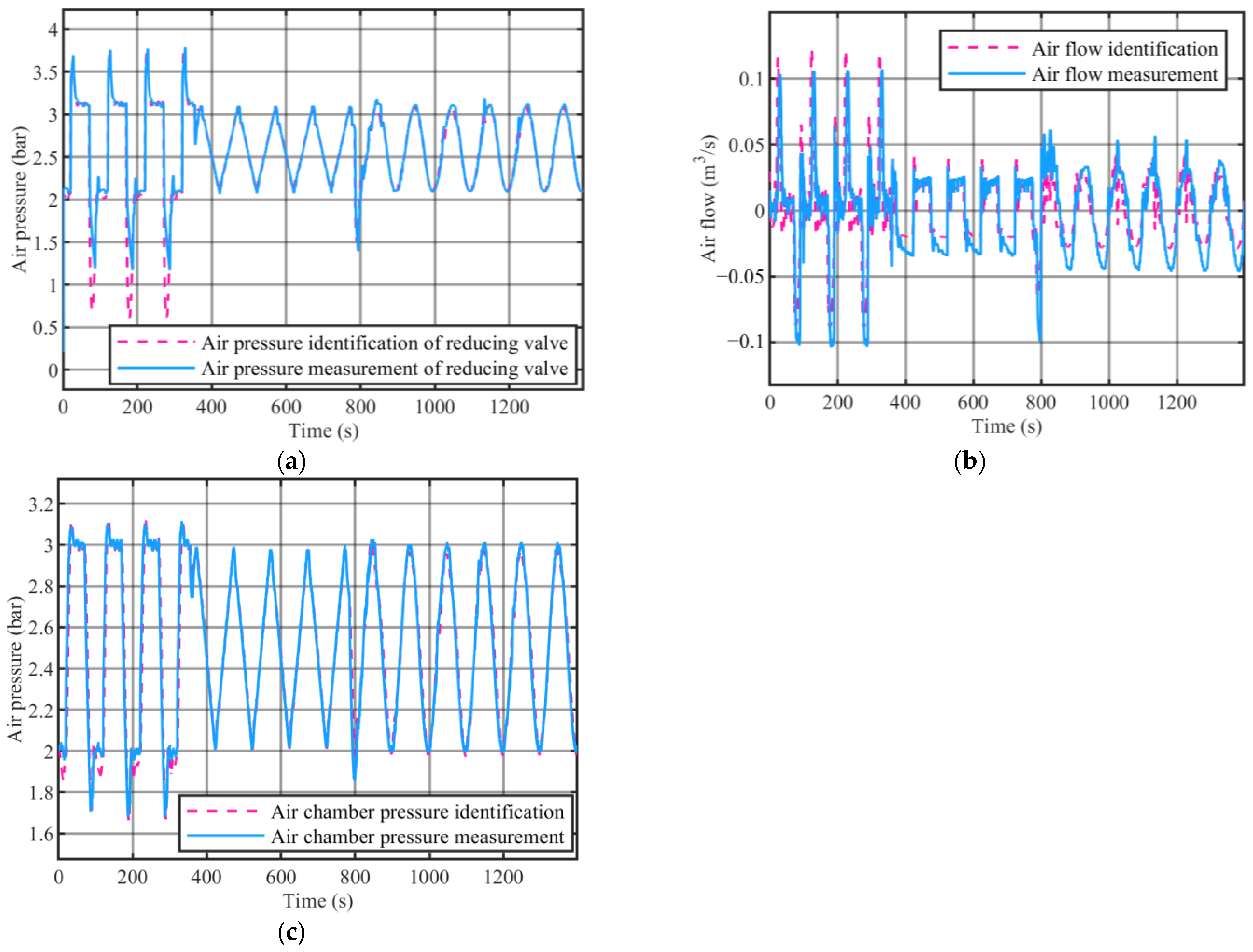
Based on experimental data obtained on the SPB shield tunneling machine test bench, the nonlinear RLSs algorithm was used to adaptively identify the uncertain parameters of the air chamber pressure regulation model. The identification results for the pilot stage pressure of the pneumatic proportional pressure-reducing valve, air flow, and air chamber pressure are shown in Figure 6. The nonlinear RLSs identification values of uncertain parameters in the air chamber pressure regulation model are shown in Table 1. The verification results indicate that the identification is highly accurate.

3. Nonlinear ARC Design for Air Chamber Pressure

For the nonlinear state space system developed in Section 2, adaptive controllers can adapt to the uncertain parameters that slowly change in the system, but, when parameters change rapidly and, over a large range, become unbounded, they can easily cause system instability [24]. Robust controllers, such as the sliding mode controller (SMC), have a unique advantage in their simplicity while achieving satisfactory steady and transient performances. However, the discontinuous control law utilized by SMC will lead to the chattering phenomena [25]. Chattering in the dynamic system may excite a high-frequency unmolded dynamic and break down the whole system. The ARC can achieve both adaptive and robust advantages by organically combining the two while removing the drawbacks of both [26]. The ARC law could achieve a guaranteed output tracking transient performance and final tracking accuracy in general while keeping all physical states and control inputs bounded. In addition, the control law achieves asymptotic output tracking in the presence of parametric uncertainties without using a discontinuous or infinite-gain feedback term [27].
For the control objectives in Equation (23), the controller based on nonlinear ARC can be designed here.
The control objectives of the air chamber pressure are
y P a = x 1 y P a d e s i r e
where y P a d e s i r e represents expected air chamber pressure reference input.
We define the tracking error as
y ˜ P a = y P a y P a _ d e s i r e
The sliding model surface is defined as
s P a = y ˜ P a + λ y ˜ P a d t
The differential of the sliding model surface is
s ˙ P a = x ˙ 1 y ˙ P a d e s i r e + λ ( x 1 y P a d e s i r e ) = f 1 ( h , x 1 ) + g 1 ( h , x 1 ) x 2 y ˙ P a d e s i r e + λ ( x 1 y P a d e s i r e )
The control objective is to design a bounded control law for the control input signal u a that is as small as possible. For differentiation of s P a , x 2 can be considered its virtual input. Then, a virtual control law α can be designed as
α = α m + α s
where
α m = 1 g 1 ( h , x 1 ) [ f 1 ( h , x 1 ) + y ˙ P a d e s i r e λ ( x 1 y P a d e s i r e ) ]
α s = 1 g 1 ( h , x 1 ) ( k 1 s P a )
Equation (33) is dynamic compensation term in feedforward form; Equation (34) is a linear feedback term that makes the system dynamically stable, where k1 is its linear feedback gain.
We define the tracking error of x2 as z 2 = x 2 α .
The differential of the tracking error z 2 is
z ˙ 2 = x ˙ 2 α ˙ = θ 1 x 2 θ 2 f 2 ( x 1 ) + θ 3 g 2 ( x 1 ) x 3 α ˙
At this point, the differential equation of the sliding model surface becomes
s ˙ P a = k 1 s P a + g 1 ( h , x 1 ) z 2
The Lyapunov function is defined as
V = 1 2 1 s P a m a x 2 s P a 2 + 1 2 1 z 2 m a x 2 z 2 2
where s P a m a x = 8 × 10 5 Pa is the max value of s P a and z 2 m a x = 0.38   m 3 / s is the max value of z 2 .
At this point, the differentiation of the Lyapunov function is
The Lyapunov function is defined as
V ˙ = 1 s P a m a x 2 s P a s ˙ P a + 1 z 2 m a x 2 z 2 z ˙ 2 = 1 s P a m a x 2 s P a [ k 1 s P a + g 1 ( h , x 1 ) z 2 ] + 1 z 2 m a x 2 z 2 [ θ 1 x 2 θ 2 f 2 ( x 1 ) + θ 3 g 2 ( x 1 ) x 3 α ˙ ]
For the differential equation of the Lyapunov function at this time, x3 can be considered its virtual input. Then, a virtual control law β can be designed as
β = β m + β s 1 + β s 2
We define the tracking error of x 3 as z 3 = x 3 β .
The differential of the tracking error z 3 is
z ˙ 3 = x ˙ 3 β ˙ = θ 4 x 3 + θ 5 u a β ˙
where
β m = 1 θ ^ 3 g 2 ( x 1 ) [ θ ^ 1 x 5 + θ ^ 2 f 2 ( x 1 ) + α ˙ z 2 m a x 2 s P a m a x 2 s P a g 1 ( h , x 1 ) ]
Equation (41) is dynamic compensation term in feedforward form, including compensation for the cross-coupling terms caused by mismatches g 1 ( h , x 1 ) z 2 between x 2 and the expected control laws α . θ ^ 1 represents the adaptive estimation value of θ 1 , θ ^ 2 represents the adaptive estimation value of θ 2 , and θ ^ 3 represents the adaptive estimation value of θ 3 . The definitions θ ˜ 1 = θ ^ 1 θ 1 , θ ˜ 2 = θ ^ 2 θ 2 , and θ ˜ 3 = θ ^ 3 θ 3 represent the parameter estimation error of θ 1 , θ 2 , and θ 3 .
We extend the tracking error z 3 to the Lyapunov function of Equation (37):
V = 1 2 1 s P a m a x 2 s P a 2 + 1 2 1 z 2 m a x 2 z 2 2 + 1 2 1 z 3 m a x 2 z 3 2
where z 3 m a x = 8 × 10 5 Pa is the max value of z 3 .
At this point, the differentiation of the Lyapunov function is
V ˙ = 1 s P a m a x 2 s P a [ k 1 s P a + g 1 ( h , x 1 ) z 2 ] + 1 z 2 m a x 2 z 2 [ θ 1 x 2 θ 2 f 2 ( x 1 ) + θ 3 g 2 ( x 1 ) x 3 α ˙ ] + 1 z 3 m a x 2 z 3 z ˙ 3 = k 1 1 s P a m a x 2 s P a 2 + 1 s P a m a x 2 s P a g 1 ( h , x 1 ) z 2 + 1 z 2 m a x 2 z 2 [ θ 1 x 2 θ 2 f 2 ( x 1 ) + θ 3 g 2 ( x 1 ) ( z 3 + β ) α ˙ ] + 1 z 3 m a x 2 z 3 z ˙ 3 = k 1 1 s P a m a x 2 s P a 2 + 1 s P a m a x 2 s P a g 1 ( h , x 1 ) z 2 + 1 z 2 m a x 2 z 2 [ θ 1 x 2 θ 2 f 2 ( x 1 ) + θ 3 g 2 ( x 1 ) ( z 3 + β s 1 + β s 2 ) + ( θ 3 θ ^ 3 + θ ^ 3 ) g 2 ( x 1 ) β m α ˙ ] + 1 z 3 m a x 2 z 3 z ˙ 3 = k 1 1 s P a m a x 2 s P a 2 + 1 s P a m a x 2 s P a g 1 ( h , x 1 ) z 2 + 1 z 2 m a x 2 z 2 [ θ 1 x 2 θ 2 f 2 ( x 1 ) + θ 3 g 2 ( x 1 ) ( z 3 + β s 1 + β s 2 ) + ( θ 3 θ ^ 3 ) g 2 ( x 1 ) β m + θ ^ 1 x 2 + θ ^ 2 f 2 ( x 1 ) + α ˙ z 2 m a x 2 s 2 max s P a g 1 ( h , x 1 ) α ˙ ] + 1 z 3 m a x 2 z 3 z ˙ 3 = k 1 1 s P a m a x 2 s P a 2 + 1 z 2 m a x 2 z 2 [ θ ˜ 1 x 2 + θ ˜ 2 f 2 ( x 1 ) θ ˜ 3 g 2 ( x 1 ) β m + θ 3 g 2 ( x 1 ) ( z 3 + β s 1 + β s 2 ) ] + 1 z 3 m a x 2 z 3 z ˙ 3
where β s 1 = 1 θ 3 m i n g 2 ( x 1 ) [ h 1 ( x 1 , x 2 ) s a t ( h 1 ( x 1 , x 2 ) 4 ε 1 z 2 ) ] is a robust feedback term which can dominate the impact of all model uncertainty. It should satisfy h 1 ( x 1 , x 2 ) | θ ˜ 1 x 2 + θ ˜ 2 f 2 ( x 1 ) θ ˜ 3 g 2 ( x 1 ) β m | .
When | h 1 ( x 1 , x 2 ) 4 ε 1 z 2 | 1 , the difference between the ideal switch function h 1 ( x 1 , x 2 ) z 2 and the smooth switch function z 2 h 1 ( x 1 , x 2 ) s a t ( h 1 ( x 1 , x 2 ) 4 ε 1 z 2 ) is zero. When | h 1 ( x 1 , x 2 ) 4 ε 1 z 2 | 1 ,
h 1 ( x 1 , x 2 ) z 2 z 2 h 1 ( x 1 , x 2 ) s a t ( h 1 ( x 1 , x 2 ) 4 ε 1 z 2 ) = h 1 ( x 1 , x 2 ) z 2 h 1 2 ( x 1 , x 2 ) 4 ε 1 z 2 2 = ε 1 [ h 1 ( x 1 , x 2 ) 2 ε 1 | z 2 | ε 1 ] 2 ε 1
So ε 1 represents the degree of approximation between a smooth switch function and an ideal switch function. A smaller ε 1 means the smooth switch function is more approximate to the ideal switch function.
We define
h 1 ( x 1 , x 2 ) = θ 1 M | x 2 | + θ 2 M | f 2 ( x 1 ) | + θ 3 M | g 2 ( x 1 ) β m |
where θ 1 M = θ 1 m a x θ 1 m i n , θ 2 M = θ 2 m a x θ 2 m i n , and θ 3 M = θ 3 m a x θ 3 m i n .
β s 2 = 1 θ 3 m i n g 2 ( x 1 ) ( k 2 z 2 )
Equation (46) is a linear feedback term that makes the system dynamically stable, where k 2 is its linear feedback gain.
In order to the eliminate control errors caused by the offline identification errors of uncertain parameters, we use the adaptive identification law in a discrete saturation mapping form:
θ ^ ˙ z 2 = Proj θ ^ z 2 ( Γ z 2 φ z 2 z 2 )
where θ ^ z 2 = [ θ ^ 1 , θ ^ 2 , θ ^ 3 ] T , φ z 2 = [ x 2 , f 2 ( x 1 ) , g 2 ( x 1 ) x 3 ] T , Γ z 2 is a diagonal adaptive law matrix for the vector · , and Proj θ ^ z 2 ( · ) is defined as
Proj θ ^ z 2 ( · ) = [ Proj θ ^ z 2 1 ( · 1 ) , Proj θ ^ z 2 2 ( · 2 ) , , Proj θ ^ z 2 p ( · p ) ] T
Proj θ ^ z 2 i ( · i ) = { 0   if   { θ ^ z 2 i = θ ^ z 2 i m a x   and   · i > 0 θ ^ z 2 i = θ ^ z 2 i m i n   and   · i < 0 · i   otherwise  
Property 1.
The mapping in Equation (49) has the following properties:
P 1.1       θ ^ z 2 ( t ) Ω ¯ θ ^ z 2 = { θ ^ z 2 : θ z 2 m i n θ ^ z 2 θ z 2 m a x } ,   t P 1.2       θ ˜ z 2 T [ Γ z 2 1 Proj θ ^ z 2 ( Γ z 2 τ ) τ ] 0 ,   t
P1.1 indicates that θ ^ z 2 can be directly applied to control laws without causing unbounded parameter estimates and resulting in system instability.
The Lyapunov function is augmented as
V = 1 2 1 s P a m a x 2 s P a 2 + 1 2 1 z 2 m a x 2 z 2 2 + 1 2 1 z 3 m a x 2 z 3 2 + 1 2 1 z 2 m a x 2 θ ˜ z 2 T Γ z 2 1 θ ˜ z 2
According to P1.2, at this point, the differentiation of the Lyapunov function is
V ˙ = k 1 1 s P a m a x 2 s P a 2 + 1 z 2 m a x 2 θ ˜ z 2 T Γ z 2 1 Proj θ ^ z 2 ( Γ z 2 φ z 2 z 2 ) + 1 z 2 m a x 2 z 2 { θ ˜ 1 x 2 + θ ˜ 2 f 2 ( x 1 ) θ ˜ 3 g 2 ( x 1 ) β m + θ 3 g 2 ( x 1 ) [ z 3 + 1 θ 3 min g 2 ( x 1 ) [ h 1 ( x 1 , x 2 ) s a t ( h 1 ( x 1 , x 2 ) 4 ε 1 z 2 ) ] + 1 θ 3 min g 2 ( x 1 ) ( k 2 z 2 ) ] } + 1 z 3 m a x 2 z 3 z ˙ 3 k 1 1 s P a m a x 2 s P a 2 k 2 1 z 2 m a x 2 z 2 2 + 1 z 2 m a x 2 θ 3 g 2 ( x 1 ) z 2 z 3 + 1 z 3 m a x 2 z 3 z ˙ 3 + 1 z 2 m a x 2 h 1 ( x 1 , x 2 ) [ sgn ( z 2 ) s a t ( h 1 ( x 1 , x 2 ) 4 ε 1 z 2 ) ] k 1 1 s P a m a x 2 s P a 2 k 2 1 z 2 m a x 2 z 2 2 + 1 z 3 m a x 2 z 3 ( z 3 m a x 2 z 2 m a x 2 θ 3 g 2 ( x 1 ) z 2 θ 4 x 3 + θ 5 u a β ˙ ) + 1 z 2 m a x 2 z 2 h 1 ( x 1 , x 2 ) [ sgn ( z 2 ) s a t ( h 1 ( x 1 , x 2 ) 4 ε 1 z 2 ) ] + 1 z 2 m a x 2 z 2 h 1 ( x 1 , x 2 ) [ sgn ( z 2 ) s a t ( h 1 ( x 1 , x 2 ) 4 ε 1 z 2 ) ]
The final control law u a is designed such that
u a = u a m + u a s 1 + u a s 2
where
u a m = 1 θ ^ 5 [ z 3 m a x 2 z 2 m a x 2 θ ^ 3 g 2 ( x 1 ) z 2 + θ ^ 4 x 3 + β ˙ ]
where Equation (54) is a dynamic compensation term in feedforward form, including compensation for the cross-coupling terms caused by mismatches θ 3 g 2 ( x 1 ) z 3 between x 3 and the expected control laws β . θ ^ 4 represents the adaptive estimation value of θ 4 and θ ^ 5 represents the adaptive estimation value of θ 5 . The definitions θ ˜ 4 = θ ^ 4 θ 4 and θ ˜ 5 = θ ^ 5 θ 5 represent the parameter estimation errors of θ 4 and θ 5 , respectively.
At this point, the differentiation of the Lyapunov function is
V ˙ k 1 1 s P a m a x 2 s P a 2 k 2 1 z 2 m a x 2 z 2 2 + 1 z 3 m a x 2 z 3 ( z 3 m a x 2 z 2 m a x 2 θ 3 g 2 ( x 1 ) z 2 θ 4 x 3 + ( θ 5 θ ^ 5 + θ ^ 5 ) u a m + θ 5 ( u a s 1 + u a s 2 ) β ˙ ) + 1 z 2 m a x 2 z 2 h 1 ( x 1 , x 2 ) [ sgn ( z 2 ) s a t ( h 1 ( x 1 , x 2 ) 4 ε 1 z 2 ) ] k 1 1 s P a m a x 2 s P a 2 k 2 1 z 2 m a x 2 z 2 2 + 1 z 3 m a x 2 z 3 ( z 3 m a x 2 z 2 m a x 2 θ ˜ 3 g 2 ( x 1 ) z 2 + θ ˜ 4 x 3 θ ˜ 5 u a m + θ 5 ( u a s 1 + u a s 2 ) ) + 1 z 2 m a x 2 z 2 h 1 ( x 1 , x 2 ) [ sgn ( z 2 ) s a t ( h 1 ( x 1 , x 2 ) 4 ε 1 z 2 ) ]
u a s 1 = 1 θ 5 m i n [ h 2 ( x 1 , z 2 , x 3 , u a m ) s a t ( h 2 ( x 1 , z 2 , x 3 , u a m ) 4 ε 2 z 3 ) ]
Equation (56) is a robust feedback term which can dominate the impact of all model uncertainties. ε 2 represents the degree of approximation between a smooth switch function and an ideal switch function for the same reasons that apply to ε 1 . Equation (56) should satisfy
h 2 ( x 1 , z 2 , x 3 , u a m ) | θ ˜ 3 g 2 ( x 1 ) z 2 + θ ˜ 4 x 3 θ ˜ 5 u a m |
We define
h 2 ( x 1 , z 2 , x 3 , u a m ) = θ 3 M | g 2 ( x 1 ) z 2 | + θ 4 M | x 3 | + θ 5 M | u a m |
where θ 4 M = θ 4 m a x θ 4 m i n and θ 5 M = θ 5 m a x θ 5 m i n .
u a s 2 = 1 θ 5 m i n ( k 3 z 3 )
Equation (59) is a linear feedback term that makes the system dynamically stable, where k 3 is its linear feedback gain.
In order to the eliminate control errors caused by the offline identification errors of uncertain parameters, we use the adaptive identification law in a discrete saturation mapping form:
θ ^ ˙ z 3 = Proj θ ^ z 3 ( Γ z 3 φ z 3 z 3 )
where θ ^ z 3 = [ θ ^ 3 , θ ^ 4 , θ ^ 5 ] T , φ z 2 = [ z 3 m a x 2 z 2 m a x 2 g 2 ( x 1 ) z 2 , x 3 , u a ] T , Γ z 3 is a diagonal adaptive law matrix for the vector · , and Proj θ ^ z 3 ( · ) is defined as
Proj θ ^ z 3 ( · ) = [ Proj θ ^ z 3 1 ( · 1 ) , Proj θ ^ z 3 2 ( · 2 ) , , Proj θ ^ z 3 p ( · p ) ] T
Proj θ ^ z 3 i ( · i ) = { 0   if   { θ ^ z 3 i = θ ^ z 3 i m a x   and   · i > 0 θ ^ z 3 i = θ ^ z 3 i m i n   and   · i < 0 · i   otherwise  
Property 2.
The mapping in Equation (62) has the following properties:
P 2.1       θ ^ z 3 ( t ) Ω ¯ θ ^ z 3 = { θ ^ z 3 : θ z 3 m i n θ ^ z 3 θ z 3 m a x } ,   t P 2.2       θ ˜ z 3 T [ Γ z 3 1 Proj θ ^ z 3 ( Γ z 3 τ ) τ ] 0 ,   t
P2.1 indicates that θ ^ z 3 can be directly applied to control laws without causing unbounded parameter estimates and resulting in system instability.
The Lyapunov function is augmented as
V = 1 2 1 s P a m a x 2 s P a 2 + 1 2 1 z 2 m a x 2 z 2 2 + 1 2 1 z 3 m a x 2 z 3 2 + 1 2 1 z 2 m a x 2 θ ˜ z 2 T Γ z 2 1 θ ˜ z 2 + 1 2 1 z 3 m a x 2 θ ˜ z 3 T Γ z 3 1 θ ˜ z 3
According to P2.2, at this point, the differentiation of the Lyapunov function is
V ˙ k 1 1 s P a m a x 2 s P a 2 k 2 1 z 2 m a x 2 z 2 2 + 1 z 3 m a x 2 θ ˜ z 3 T Γ z 3 1 Proj θ ^ z 3 ( Γ z 3 φ z 3 z 3 ) + 1 z 3 m a x 2 z 3 { θ ˜ 3 g 2 ( x 1 ) z 2 + θ ˜ 4 x 3 θ ˜ 5 u a m + θ 5 [ 1 θ 5 min [ h 2 ( x 1 , z 2 , x 3 , u a m ) s a t ( h 2 ( x 1 , z 2 , x 3 , u a m ) 4 ε 2 z 3 ) ] + 1 θ 5 min ( k 3 z 3 ) ] } + 1 z 2 m a x 2 z 2 h 1 ( x 1 , x 2 ) [ sgn ( z 2 ) s a t ( h 1 ( x 1 , x 2 ) 4 ε 1 z 2 ) ] k 1 1 s P a m a x 2 s P a 2 k 2 1 z 2 m a x 2 z 2 2 k 3 1 z 3 m a x 2 z 3 2 + 1 z 2 m a x 2 z 2 h 1 ( x 1 , x 2 ) [ sgn ( z 2 ) s a t ( h 1 ( x 1 , x 2 ) 4 ε 1 z 2 ) ] + 1 z 3 m a x 2 z 3 h 2 ( x 1 , z 2 , x 3 , u a m ) [ sgn ( z 3 ) s a t ( h 2 ( x 1 , z 2 , x 3 , u a m ) 4 ε 2 z 3 ) ] min ( k 1 s P a m a x 2 , k 2 z 2 m a x 2 , k 3 z 3 m a x 2 ) ( s P a 2 + z 2 2 + z 3 2 ) + ε 1 z 2 m a x 2 + ε 2 z 3 m a x 2
By Barbalat’s lemma [28]:
(1)
The Lyapunov function can decay exponentially to the exact accuracy ε 1 z 2 m a x 2 + ε 2 z 3 m a x 2 min ( k 1 s P a m a x 2 , k 2 z 2 m a x 2 , k 3 z 3 m a x 2 ) with convergence rate min ( k 1 s P a m a x 2 , k 2 z 2 m a x 2 , k 3 z 3 m a x 2 ) , and the upper bound of the exponential convergence rate and tracking error steady-state values can be freely adjusted through the controller parameters min ( k 1 s P a m a x 2 , k 2 z 2 m a x 2 , k 3 z 3 m a x 2 ) and ε 1 z 2 m a x 2 + ε 2 z 3 m a x 2 . The tracking control error of the slurry level can achieve its predetermined transient and steady-state performance.
(2)
If, within a finite time, the slurry level control system only has parameter uncertainty and no unmodeled error, then the slurry level tracking control error can gradually converge to zero. Furthermore, if the control input satisfies the Persistent Excitation condition (PE condition), the estimated parameter values θ ^ z 2 and θ ^ z 3 can converge to their true values θ z 2 and θ z 3 respectively.
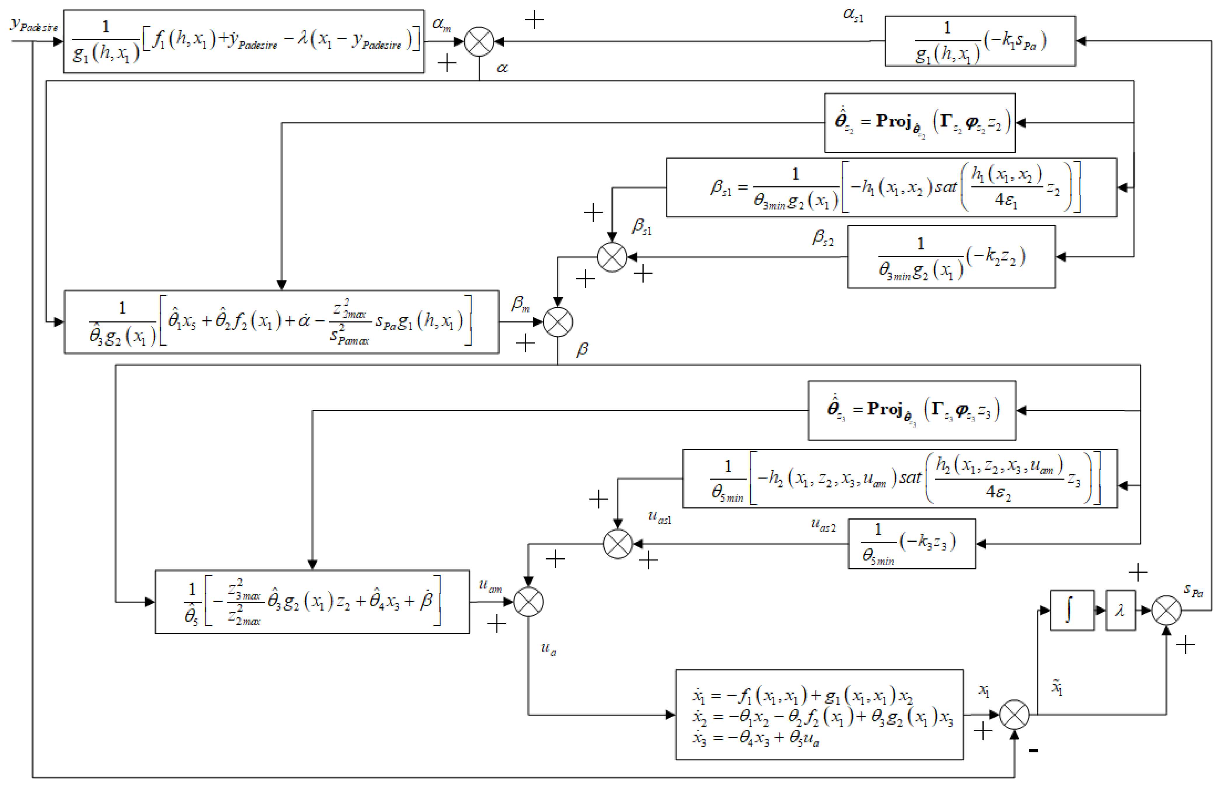
This small section fully considered the slurry level disturbance of the air chamber pressure model and then designed a nonlinear ARC law for air chamber pressure control to improve the robustness of the air chamber pressure to slurry level disturbances. At the same time, online adaptive identification of time-varying uncertain model parameters was adopted to improve steady-state accuracy and a Lyapunov stability proof was conducted. The block diagram of the ARC for air chamber pressure is shown in Figure 7, in which the bold represents vectors or matrices.
In the following sections, the designed ARC for air chamber pressure will be verified through simulation and experiment.

4. Verification

4.1. Simulation Verification

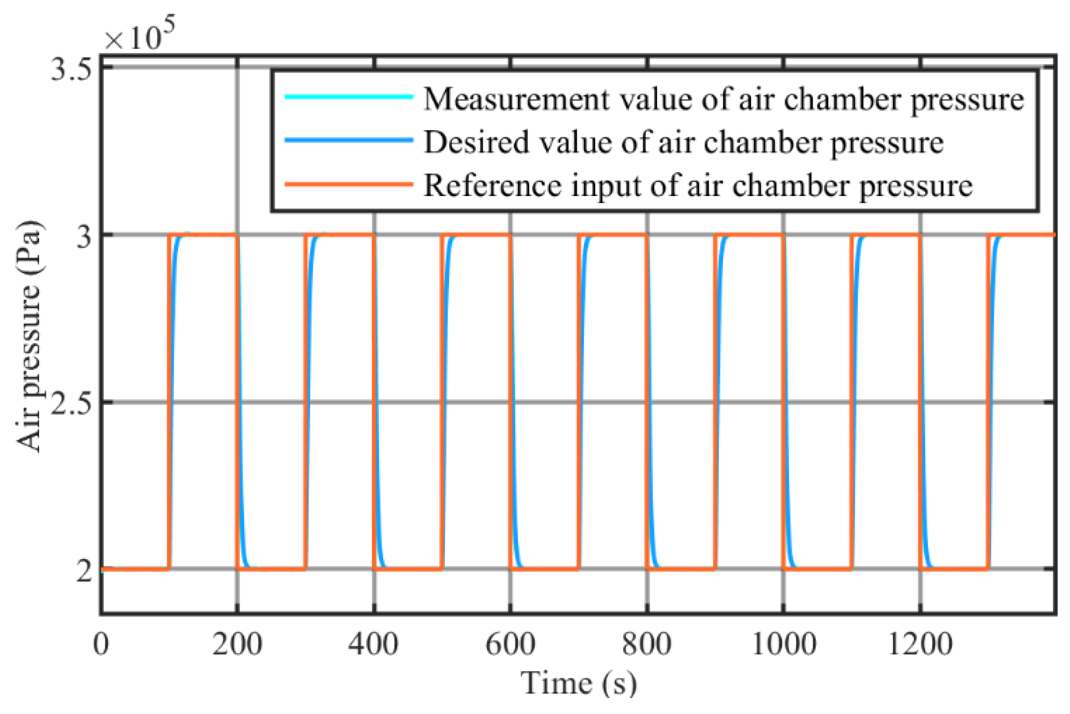
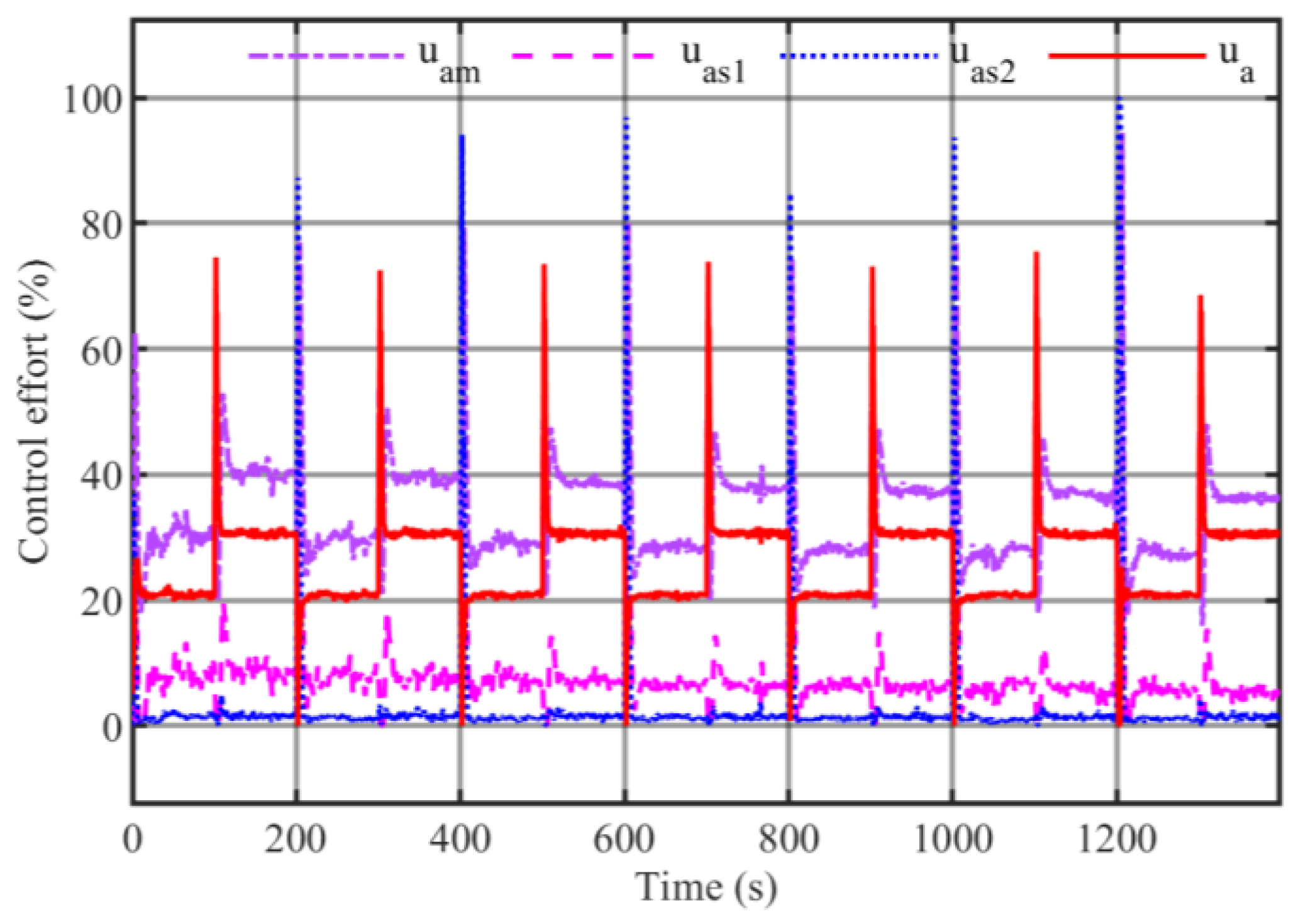
Based on the designed nonlinear ARC law for the air chamber pressure regulation system, a simulation investigation was conducted under slurry level disturbances in excavation strata. The known parameters, gain, and coefficients used for the simulation and experiment are shown in Table 2. Firstly, a model of the air chamber pressure’s nonlinear ARC under slurry level disturbance was built using Simulink. In the simulation, the reference input for the air chamber pressure was a square wave signal, and the simulation curve is shown in Figure 8. It can be observed that the green measurement value of the air chamber pressure can track the blue desired value of the air chamber pressure well in Figure 8. The stable time is 6.44 s when the air chamber pressure rises in the simulation, and the relative steady-state error is less than ±0.25%; the stable time is 5.30 s when the air chamber pressure decreases, and the relative steady-state error is less than ±0.25%. The simulation of air chamber pressure PID control was conducted as a comparison with the nonlinear ARC. The stable time is 11.63 s when the air chamber pressure rises in the simulation, and the relative steady-state error is less than ±0.50%; the stable time is 9.14 s when the air chamber pressure decreases, and the relative steady-state error is less than ±0.50%. The dynamic and static performance comparison of the nonlinear ARC and PID controller for the air chamber pressure is shown in Table 3. It can be observed that the transient and steady performance of nonlinear ARC is better than that of the traditional PID controller, especially in the presence of slurry level disturbances. The curves of the ARC effort for u a , u a m , u a s 1 , and u a s 2 are shown in Figure 9.

4.2. Experiment Verification

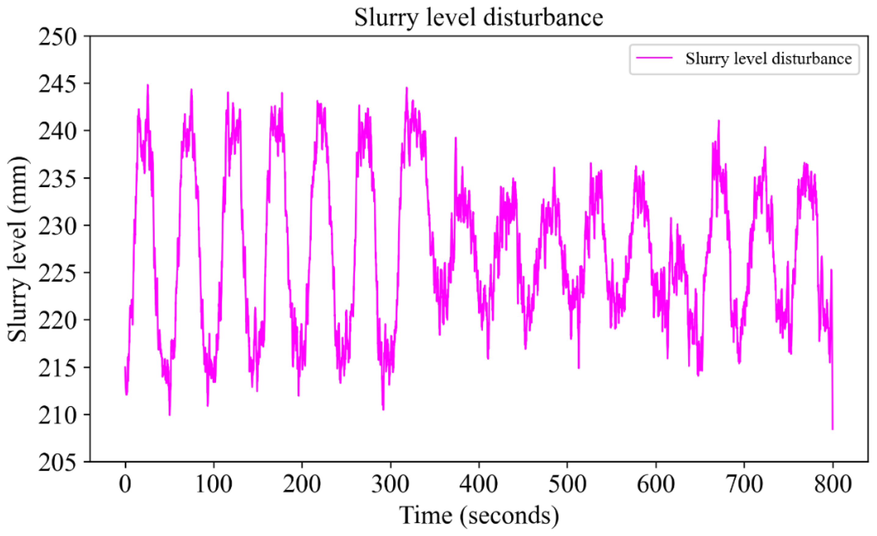
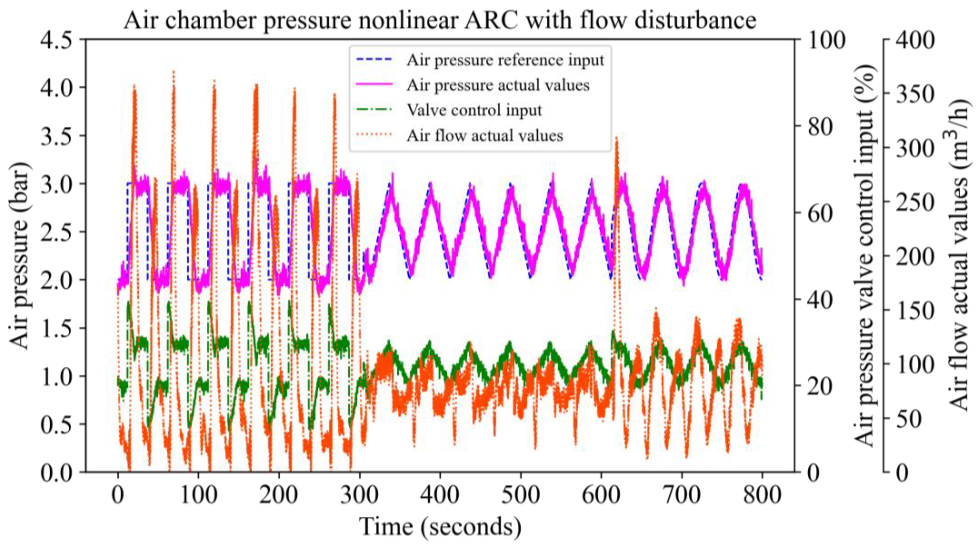
Based on the developed SPB shield tunneling machine test bench, an experiment on the performance of the air chamber pressure nonlinear ARC under level disturbances caused by slurry input and output flow disturbances was carried out. In the experiment, the reference input of the air chamber pressure included continuous step signals, triangular wave signals, and sine signals. The slurry level disturbance is shown in Figure 10. The experimental curve is shown in Figure 11. It can be observed that the magenta measured values of air chamber pressure can track the blue reference input of the air chamber pressure well under slurry level disturbances.
The designed nonlinear ARC can compensate for the nonlinear disturbance in the air chamber pressure caused by the slurry level in order to improve the control accuracy of air chamber pressure. The stable time is 7.40 s when the air chamber pressure rises in the experiment, and the relative steady-state error is less than ±2.5%; the stable time is 9.20 s when the air chamber pressure decreases, and the relative steady-state error is less than ±2.5%. The dynamic and static performances of the nonlinear ARC for air chamber pressure are shown in Table 4.

5. Conclusions

This paper proposed a novel air chamber pressure control method for SPB shield machines which can adapt to complex and variable slurry level disturbances. An electric proportional air chamber pressure regulation system was developed using a pneumatic, proportional, three-way, pressure-reducing valve. The nonlinear state space model for the air chamber pressure regulation process was established. The coupling mechanism of the air chamber pressure regulation process was then analyzed and elucidated. This analysis revealed the nonlinear interactions between several key factors: the air chamber pressure, the height of the slurry level, the flow rate through the pressure-reducing valve, and the pressure at the pilot stage of the pressure-reducing valve. Nonlinear adaptive identification was carried out based on the experimental data of the SPB shield tunneling machine test bench. Then, a nonlinear adaptive robust controller for air chamber pressure was designed based on the backstepping method, and its Lyapunov stability was proved. Finally, the feasibility and effectiveness of the controller designed in this paper have been verified through simulation and experiments. Compared to the manual control method currently used in practical engineering, which relies on a pressure-reducing valve with a mechanical PID controller, the ARC method proposed in this paper achieves superior dynamic and steady-state control performances. It also demonstrates better adaptation to model uncertainties and disturbances and offers increased robustness.
Future work will focus on implementing the proposed air chamber pressure ARC system for its engineering verification in real-world shield tunneling projects.

Author Contributions

S.W. and Y.Z. designed the research. S.W. wrote the first draft of the manuscript. H.Y. reviewed this work and contributed via discussion. Y.Z. and G.G. revised and edited the final version. All authors have read and agreed to the published version of the manuscript.

Funding

This research was funded by the National Natural Science Foundation of China (Grant No. 52105074), the National Key Research and Development Program of China (Grant No. 2022YFC3802305), and the Open Project of State Key Laboratory of Shield Machine and Boring Technology (Grant No. SKLST-2021-K02).

Data Availability Statement

The data presented in this study are available on request from the corresponding author due to privacy.

Acknowledgments

Special thanks to the China Railway Engineering Equipment Group Co, Ltd. for providing construction field data.

Conflicts of Interest

The authors declare no conflicts of interest.

Nomenclature

A v 1 Effective working area of pilot valve spool m a Compressed air quality of air chamber
A v 2 Effective working area of the pressure P 1 -acting end of the main valve spool m v 1 Total mass of the moving iron spool and the pilot valve spool
A v 3 Effective working area of the outlet end of the main valve spool m v 2 Quality of the main valve spool
B v 1 Viscous damping coefficient of the pilot valve spool P 1 Pilot valve outlet pressure
B v 2 Viscous damping coefficient of the main valve spool P a Air pressure in air chamber
C d v 1 Flow coefficient of the pilot valve port P a _ d e s i r e Expected air chamber pressure value
C d v 2 Flow coefficient of the main valve port P d Downstream pressure
d v 1 Diameter of the pilot valve spool P s Pressure at the center point of the slurry chamber
d v 2 Diameter of the main valve spool P u Upstream pressure
F m Proportional electromagnetic output force r Inner radius of the air chamber
h Slurry level height in slurry chamber R Radius of the cutterhead
I Current of coil R a Ideal gas constant
κ Gas adiabatic index of compressed air R e Total coil resistance
K e Counter electromotive force coefficient T 1 Absolute temperature of the air at the outlet of the pilot valve
K f 1 Steady-state hydrodynamic coefficient of the pilot valve spool T a Absolute temperature of the compressed air in the air chamber
K f 2 Steady state hydrodynamic coefficient of the main valve spool T u Absolute temperature of upstream air
K I Current force gain coefficient u a Control input of pilot-operated pneumatic proportional three-way pressure-reducing valve
K P 1 Reciprocal of the inertia time constant of the pilot valve port pressure U V Voltage of electromagnet
Gain of pilot valve port pressure V 1 Pilot valve outlet volume
K Q 1 Reciprocal of the inertia time constant of the volume flow rate of compressed air at the main valve V ˙ a Volume change rate of the compressed air in the air chamber
K Q P 1 Flow pressure coefficient of the pilot valve x ˙ Shield thrust speed
K Q P a Flow pressure coefficient of the main valve x v 1 Pilot valve spool displacement
K s 1 Pilot valve spool reset spring stiffness x ˙ v 1 Pilot valve spool velocity
K v 2 Stiffness of the reset spring on the pressure P 1 connection side of the main valve spool x ¨ v 1 Pilot valve spool acceleration
K v 3 Stiffness of the reset spring on the outlet side of the main valve spool x v 2 Main valve spool displacement
K x Displacement force gain coefficient x ˙ v 2 Main valve spool velocity
L Inductance of coil x ¨ v 2 Main valve spool acceleration
m 1 Pilot valve outlet air quality

References

  1. Shen, X.; Chen, Y.F.; Cao, L.Q.; Chen, X.S.; Fu, Y.B.; Hong, C.Y. Prediction of the slurry pressure and inversion of formation characteristics based on a machine learning algorithm during tunneling in a fault fracture zone. Tunneling Undergr. Space Technol. 2024, 144, 105514. [Google Scholar] [CrossRef]
  2. Xu, D.M.; Wang, Y.S.; Huang, J.Q.; Liu, S.J.; Xu, S.J.; Zhou, K. Prediction of geology condition for slurry pressure balanced shield tunnel with super-large diameter by machine learning algorithms. Tunneling Undergr. Space Technol. 2023, 131, 104852. [Google Scholar] [CrossRef]
  3. Liu, X.; Liu, D.; Chen, Q.; Zhou, X.; Xiong, F. Research on the Sensitivity of Factors Affecting the Stability of Slurry Shield Excavation Face and Control Parameter Optimization. Chin. J. Undergr. Space Eng. 2022, 18, 1954–1961. [Google Scholar]
  4. Zizka, Z.; Schoesser, B.; Thewes, M. Physical modelling of transient processes at the slurry supported tunnel face during shield excavation. In Proceedings of the 10th International Symposium on Geotechnical Aspects of Underground Construction in Soft Ground (IS-Cambridge), Cambridge, UK, 29 June–1 July 2022; pp. 482–489. [Google Scholar]
  5. Wang, Q.; Xie, X.Y.; Shahrour, I.; Huang, Y. Use of deep learning, denoising technic and cross-correlation analysis for the prediction of the shield machine slurry pressure in mixed ground conditions. Autom. Constr. 2021, 128, 103741. [Google Scholar] [CrossRef]
  6. Shen, X.; Yuan, D.; Wu, J.; Li, X.; Jin, D.; Wang, T. Development and Application of Model Test Platform for Slurry Balance Shield Under High Water Pressure. China J. Highw. Transp. 2020, 33, 164–175. [Google Scholar]
  7. Liu, X.; Wang, F.; Yuan, D.; Fang, H.; Zhang, S. Range of support pressures for slurry shield and analysis of its influence factors. Chin. J. Geotech. Eng. 2019, 41, 908–917. [Google Scholar]
  8. Qi, C.; He, C.; Feng, K.; Tang, Y.; Wang, W.; Xia, W. Development and application of simulation test system for slurry balance shield. Chin. J. Geotech. Eng. 2016, 38, 1999–2008. [Google Scholar]
  9. Liu, Q.; Yang, Z. Model test research on excavation face stability of slurry balanced shield in permeable sand layers. Rock Soil Mech. 2014, 35, 2255–2260. [Google Scholar]
  10. Wei, D.W.; Zhu, W.; Min, F.L.; Xia, S.Q. Experimental Study on the Balance Law Between Slurry Pressure and Effective Stress in a Slurry Shield. In Proceedings of the International Symposium on Geotechnical Engineering for High-Speed Transportation Infrastructure (IS-GeoTrans), Hangzhou, China, 26–28 October 2012; pp. 210–219. [Google Scholar]
  11. Song, Y.; Xu, B. Initial Parameters for Bubble Cabin of Large Diameter Slurry Shield. J. Tongji Univ. Nat. Sci. 2010, 38, 1221–1225. [Google Scholar]
  12. Li, Y.; Zhang, Z.; Zhang, G. Laboratory study on face stability mechanism of slurry shields. Chin. J. Geotech. Eng. 2007, 29, 1074–1079. [Google Scholar]
  13. Zhang, Y.K.; Gong, G.F.; Yang, H.Y.; Li, W.J.; Liu, J. Precision versus intelligence: Autonomous supporting pressure balance control for slurry shield tunnel boring machines. Autom. Constr. 2020, 114, 103173. [Google Scholar] [CrossRef]
  14. Li, X.F.; Gong, G.F. Objective-oriented genetic algorithm based dynamical sliding mode control for slurry level and air pressure in shield tunneling. Autom. Constr. 2020, 109, 102987. [Google Scholar] [CrossRef]
  15. Li, X.F.; Gong, G.F. Predictive control of slurry pressure balance in shield tunneling using diagonal recurrent neural network and evolved particle swarm optimization. Autom. Constr. 2019, 107, 102928. [Google Scholar] [CrossRef]
  16. Li, X.; Zhang, H.; Xue, Y.; Shao, C. Pressure Balance Control System for Slurry Shield Based on Predictive Function Control; Springer International Publishing: Cham, Switzerland, 2015; pp. 501–510. [Google Scholar]
  17. Zhou, C.; Ding, L.Y.; He, R. PSO-based Elman neural network model for predictive control of air chamber pressure in slurry shield tunneling under Yangtze River. Autom. Constr. 2013, 36, 208–217. [Google Scholar] [CrossRef]
  18. Song, Y.; Xi, Y.; Li, W. Simulation Design on Balance Control System for Excavating Face of Slurry Shield. J. Tongji Univ. Nat. Sci. 2010, 38, 574–579. [Google Scholar]
  19. Zhang, Y.K.; Gong, G.F.; Yang, H.Y.; Chen, Y.X.; Chen, G.L. Towards autonomous and optimal excavation of shield machine: A deep reinforcement learning-based approach. J. Zhejiang Univ. -Sci. A 2022, 23, 458–478. [Google Scholar] [CrossRef]
  20. Dong, D.; Li, X. Simulation and Experimental Research on the Response of a Novel High-pressure Pneumatic Pilot-operated Solenoid Valve. In Proceedings of the 19th International Conference on Mechatronics and Machine Vision in Practice (M2VIP), Auckland, New Zealand, 28–30 November 2012; pp. 480–484. [Google Scholar]
  21. Wu, B.J. Research on High-Pressure Servo Cylinder and High-Pressure Pneumatic Servo Position System. Ph.D. Thesis, Huazhong University of Science and Technology, Wuhan, China, 2002. [Google Scholar]
  22. Yuan, H.J. Recursive least squares algorithm for nonlinear systems with piece-wise linearities. In Proceedings of the 2nd International Conference on Sensors, Measurement and Intelligent Materials (ICSMIM 2013), Guangzhou, China, 16–17 November 2013; Volume 475–476, pp. 960–963. [Google Scholar]
  23. Juang, J.G.; Lin, B.S. Nonlinear system identification by evolutionary computation and recursive estimation method. In Proceedings of the American Control Conference 2005 (ACC), Portland, OR, USA, 8–10 June 2005; pp. 5073–5078. [Google Scholar]
  24. Reed, J.S.; Ioannou, P.A. Instability analysis and robust adaptive-control of robotic manipulators. IEEE Trans. Robot. Autom. 1989, 5, 381–386. [Google Scholar] [CrossRef]
  25. Qu, Z.H. Robust-control of nonlinear uncertain systems under generalized matching conditions. Automatica 1993, 29, 985–998. [Google Scholar] [CrossRef]
  26. Yao, B.; Tomizuka, M. Adaptive robust control of SISO nonlinear systems in a semi-strict feedback form. Automatica 1997, 33, 893–900. [Google Scholar] [CrossRef]
  27. Xu, L.; Yao, B. Adaptive robust precision motion control of linear motors with negligible electrical dynamics: Theory and experiments. In Proceedings of the 2000 American Control Conference (ACC 2000), Chicago, IL, USA, 28–30 June 2000; pp. 2583–2587. [Google Scholar]
  28. Narendra, K.S.; Annaswamy, A.M. A new adaptive law for robust adaptation without persistent excitation. IEEE Trans. Autom. Control 1987, 32, 134–145. [Google Scholar] [CrossRef]
Figure 1. Idealized analytical model of the air chamber regulation process of a pilot-operated pneumatic proportional three-way pressure-reducing valve.
Machines 12 00457 g001
Figure 2. Hardware architecture of electric proportional regulation system for air chamber pressure.
Machines 12 00457 g002
Figure 3. Diagram of the electric proportional regulation system for air chamber pressure.
Machines 12 00457 g003
Figure 4. Slurry pressure loading and the closed slurry circulation loop.
Machines 12 00457 g004
Figure 5. Diagram of the Ø2.5 m SPB shield tunnel machine test bench.
Machines 12 00457 g005
Figure 6. Identification results: (a) identification results of pilot stage pressure of pneumatic proportional pressure-reducing valve; (b) identification results of air flow; (c) identification results of air chamber pressure.
Machines 12 00457 g006
Figure 7. Block diagram of the nonlinear ARC for air chamber pressure.
Machines 12 00457 g007
Figure 8. Simulation curve of nonlinear ARC for air chamber pressure.
Machines 12 00457 g008
Figure 9. Simulation curve of control effort.
Machines 12 00457 g009
Figure 10. Curve of slurry level disturbance.
Machines 12 00457 g010
Figure 11. Experimental curve of nonlinear ARC for air chamber pressure.
Machines 12 00457 g011
Table 1. Nonlinear recursive least squares identification values of unknown parameters in the air chamber pressure regulation model.
ParameterValue
θ 1 8.00
θ 2 1.2 × 10⁻⁷
θ 3 1.6 × 10⁻⁷
θ 4 1.00
θ 5 10,250
Table 2. Known parameters, gain, and coefficients used for simulation and experiment.
ParameterValueParameterValue
R 1.215 m P T 101,325 Pa
r 0.71 m ε 1 0.02
w 0.595 m k 2 0.1
κ 1.4 Γ z 2 diag (200, 3 × 10⁻¹⁴, 6 × 10⁻¹⁴)
R a 287 J/(kg·K) ε 2 30,000
λ 0.01 k 3 5
k 1 0.5 Γ z 3 diag (6 × 10⁻¹⁴, 1 × 10⁻¹³, 1 × 10⁻⁵)
Table 3. Control performance comparison between nonlinear ARC and PID step responses for air chamber pressure regulation in simulation.
ControllerStability Time (95%)Steady-State Error
Rise (Nonlinear ARC)6.44 s±0.25%
Decline (Nonlinear ARC)5.30 s±0.25%
Rise (PID)11.63 s±0.50%
Decline (PID)9.14 s±0.50%
Table 4. Control performance of nonlinear ARC step response for air chamber pressure regulation in experiment.
Stability Time (95%)Steady-State Error
Rise7.40 s±2.50%
Decline9.20 s±2.50%
Disclaimer/Publisher’s Note: The statements, opinions and data contained in all publications are solely those of the individual author(s) and contributor(s) and not of MDPI and/or the editor(s). MDPI and/or the editor(s) disclaim responsibility for any injury to people or property resulting from any ideas, methods, instructions or products referred to in the content.