Article

Experimental Evaluation of Flexible Fixture Stiffness for Steering Knuckles When Loading a Milling Machine Tool

by
Vitalii Kolesnyk
1,*,
Marcel Kuruc
2,
Ivan Dehtiarov
1,
Anna Neshta
1,
Serhii Avramenko
1,
Vitalii Kononovych
1,
Oksana Dynnyk
3,
Andrii Dovhopolov
1,
Serhii Lemekh
1 and
Roman Titskyi
1
1
Department of Manufacturing Engineering, Machines and Tools, Sumy State University, Kharkivska Str., 116, 40007 Sumy, Ukraine
2
Faculty of Materials Science and Technology, Slovak University of Technology, Jána Bottu Str., 25, 917 23 Trnava, Slovakia
3
Classical Professional College, Sumy State University, Sadova Str., 39, 41615 Konotop, Ukraine
*
Author to whom correspondence should be addressed.
Machines 2024, 12(6), 405; https://doi.org/10.3390/machines12060405
Submission received: 9 May 2024 / Revised: 3 June 2024 / Accepted: 8 June 2024 / Published: 12 June 2024

Abstract

:
In the conditions of the increase in the range of products in the automobile and aircraft industry, there is a tendency to increase the scope of application of flexible fixtures. Thus, in the current article, it was proposed to consider a new concept of a flexible fixture for location parts of a complex shape. The stress and deflection of the steering knuckle elements were calculated using finite element modeling. During the experiment on the static loading, the deflection of the steering knuckle elements was measured, and the results of finite element modeling were validated. It was determined that the stiffness of the proposed flexible fixture ensures compliance with the tolerances of the mutual location of the surfaces of the part, making it reasonable for feature research the novel flexible fixture design during milling.

1. Introduction

The inaccuracies are recognized in dimensions, shapes, and mutual position. Inaccuracy can also be defined as deviations from ideal dimensions, shapes, and the relative position of the part’s surface. The physical causes of deviations from the desired dimensions, shapes, and position of parts surfaces during machining are inaccuracies in the mutual adjustment of the tool, i.e., the workpiece [1], flexibility of the machine–fixture–workpiece system, temperature deformations of the machine–fixture–workpiece system, dimensional wear of the tool, internal tension of the workpiece [2], and deformations caused by clamping forces [3]. Another aspect that affects inaccuracy, form, and size deviations are cutting parameters [4]. Among which cutting speed, feed rate, and depth of cut are the most significant ones. Their influence has a complex effect on machining, i.e., it can lead to high vibrations, cutting tool thermal expansion, or rapid wear. However, in many cases, accuracy of basing in fixture dominates under the cutting parameters effect [5].

State of the Art

Machining of parts with complex forms is often associated with inaccuracy, which corresponds to workpiece deflection under high cutting forces, which may occur because of the allowance deviation [6]. The clamping force also plays a significant role in ensuring minimal deformation of the workpiece, which can be achieved by properly positioning fixture elements [7,8].
The location of parts during machining is an essential aspect of ensuring quality when machining [9]. They provide a rigid and stationary position of the workpiece during machining, which guarantees the accuracy of the dimensions and geometry of the finished part [10]. The correct design of the fixture determines the method of fixing the workpiece, the use of technological capabilities of the machine tool, the choice of cutting parameters [11], and the trajectory of the tool [12]. It significantly affects the setup time of mechanical operations [13]. Currently, approximately fifty-two fixture concepts have been developed. These concepts can be classified into two main groups, i.e., dedicated and standard fixtures. The group of dedicated fixtures is rapidly growing and offers more advantages for the industry. Dedicated fixtures can be component-integrated fixture features (CFFs), feature-based fixturing (FBF), robot-based fixtures (RBFs), flexible fixtures (FFs), modular + singular flex and fixture systems (M + SFFSs), and fixture change systems (FCSs). Though the number of product variants in the automobile industry will not change significantly in the long-term trend, the trend of individualization of part geometry will increase the diversity in shapes and forms of the automobile [14] and aeroengine [15] components. The rapid development of dedicated fixtures is also explained by their potential to be quickly adopted in computer-integrated manufacturing environments [16]. Combined with machine learning techniques, the configuration of flexible fixtures can be optimized to improve clamping schemes [17]. Good potential for structural optimization has a transformable pin array fixture system, comprised of reconfigurable pin array fixtures, that locates and holds parts for assembly and supports parts of different shapes adaptably [18]. Also, dedicated self-adaptive fixtures are available in airplane turbine production [19,20].
One of the crucial directions in investigations of flexible fixture construction is evaluating their stiffness [9,21,22] and stress–strain states [23]. Currently, the most promising tools of fixture research are digital twin technology, artificial intelligence, finite element methods, topology, and parameter optimization [24]. In particular, the technology of digital twins allows the creation of virtual models of machine tools that simulate their behavior in actual conditions and is an effective research tool for optimizing the characteristics of machine tools without the risk of damage to physical equipment [25]. It can also be used to predict component service life and vibration. With the help of an artificial neural network, the data on the fixture’s operation and the layout of fixture fasteners were analyzed [26]. However, the artificial neural network can also be used for a multi-objective approach for automated fixture synthesis [27], deformation force monitoring methods during machining in dedicated fixtures [28], clamping force prediction [29], and even for evaluating the effect of cutting parameters on hole accuracy during machining. Topology optimization appears to be a good solution to improve the shape of fixture parts. As a result of topology optimization utilization, it is possible to improve the trajectory of the cutting tool [30], improve the quality of parts, and reduce the consumption of materials during its production [31]. Feature optimization of the structure design of dedicated fixtures can reduce the positioning error up to 4 µm [32].
Currently, finite element modeling (FEM) is one of the most reliable methods of investigation of deflection and stress–strain states. Complex assemblies can be designed manually or using Feeman chain code [33]. Li E. et al. developed a deformation prediction method based on the spatiotemporal correlation evolution of workpiece geometry, cutting loads, and deformation. Such a calculational setup converts quantities of geometric and physical parameters related to machining deformation [34,35]. A proper clamping scheme can reduce the axial deformation of the part when welding, which was calculated via FEM in SYSWELD software [36]. Based on the FEM calculated and facilitated with optimization of the loading scheme, the proper position of clamps to avoid workpiece deflection was proposed [37]. The impact of alignment uncertainty on workpiece positioning can be evaluated by geometric dimensions and tolerance models using Monte Carlo simulation [38]. At the same time, via the combination of FEM and machine learning techniques, the optimal position of the workpiece fixture was determined [39]. Another application of FEM in the evaluation of the quality parameters of the machining process is the definition of surface flatness and elastic deformation during machining [40]. Weichang G. et al. conducted FEM milling in ABAQUS software based on the dynamic model of mechanical/magnetorheological composite clamping milling. In such a way, the natural frequency ωw and dynamic displacement qw, m(t) of the workpiece were defined [41]. Another application of FEM for flexible fixtures calculates the deformation and fixture of the elastic diaphragm. The system was determined to ensure up to 4 µm location accuracy [3,42]. One more aspect that was studied with FEM was machining error during milling [43]. The developed methodology helped evaluate the fixture scheme’s effect on cutting force and machining error [6]. The finite element analysis study evaluated the effect of clamping force on the von Misses stress and workpiece deformation [44,45].
The current paper is focused on the FEM and experimental validation of techniques for validation workpiece deflection at the milling machine tool. The present research proposes that the dedicated, flexible fixture can provide sufficient processing accuracy and that stress in various steering knuckle components under static load be evaluated. Based on these calculations, it is proposed to evaluate the allowable margin for movements at individual transition ranges for each element of the steering knuckle to define the maximum allowable error of machining. In such a way, positioning error and accuracy of basing for the proposed dedicated fixture concept for machining steering knuckles will be defined.

2. Materials and Methods

The present study proposed that the deflection and stress state of the steering knuckle in the dedicated flexible fixture be investigated. For that purpose, the following research methodology was proposed:
(1)
To develop the design of the flexible fixture based on the principles of incomplete locating for machining the maximum number of surfaces of the steering knuckle in one setup.
(2)
To conduct a study of the stress–strain state of the proposed construction using FEM methods.
(3)
Perform experimental studies of the developed design of the flexible fixture and compare them with the results of FEM.
The steering knuckle is a crucial element of the front steering system. It transmits rotational movement to the wheels relative to their vertical axis from the steering wheel through the steering system, enabling them to turn at the desired angle.
The steering knuckles have a rather complex spatial geometric shape, which is due to their purpose and the need to be a connecting link between many parts of the car steering system, such as ball bearings, hubs, ends of the steering rods, shock absorber assemblies, and brackets of the brakes. The steering knuckle plays a significant role in the running system because it contains a wheel hub bearing in its housing. It belongs to the running system, but it includes steering control elements. Generally, the steering knuckle is made of Steel 41Cr4 AISI 5140 with the following chemical composition (Table 1) and mechanical properties (Table 2) considered during finite element modeling.
The factors as mentioned above, as well as the analysis of the designs of several rotary jaws of cars and all-terrain vehicles (ATVs) (Figure 1), indicate that this part refers to the parts of a complex geometric shape, which contains from three to six smooth holes of conical or cylindrical shape and from five to ten threaded holes. At the same time, the holes and surfaces of the nuts are located at angles in different coordinate planes, which significantly complicates the machining process and requires the use of 5-axis CNC machine tools. However, the number of holes may be more significant depending on the complexity of the product.
Steering knuckles must withstand constant mechanical loads without the risk of part deformation, so the main requirements for the knuckle material are its sufficient hardness and, at the same time, high bending strength.
Thus, the bracket in the unit only rotates around the axis; high runout tolerances of its surfaces are not required. However, position tolerance of the steering knuckle surfaces must be ensured. This condition must be secured at the manufacturing steps of machining. At the same time, the main base is the hole for the hub bearing.
The object of the study was the steering knuckles of middle-class cars and powerful quad bikes (Figure 1), which have the following parameters:
-
Overall dimensions: l × b × h = 120 × 80 × 70–180 × 105 × 100 mm.
-
Mass, m = 1.1–2.5 kg.
-
Accuracy of the central holes—IT 7.
-
Accuracy of the auxiliary holes—IT 7–IT9.
-
Roughness of the auxiliary hole walls and flat surfaces, Ra 1.6–3.2 µm.
In this article, the most common design of steering knuckles was considered (Figure 1), with two main arms equidistant from the axis of the central hole and four auxiliary arms, one of which is located at an angle to the other in the vertical plane (Figure 1d), which in one or another modification is widely used in light-class cars with a capacity of up to 100 horsepower or an engine of up to 1800 cm3.
Currently, there is a wide variety of cars of the light class and other equipment, which includes steering knuckles, on the world markets and in the use of the population. However, as can be seen from Figure 1. Their designs are very similar, and the difference can only be in standard sizes and some design parameters. Therefore, the machining is given a range of products of these parts in one device can be implemented. It is advisable to machine such parts on modern five-axis CNC machines, which have the function of automatic binding to the machine’s workpiece and can be oriented in any way relative to the machine elements. This makes it possible to depart from the principle of complete orientation of the workpiece in the device, ensuring sufficiently reliable clamping and excluding any displacements during the machining.
This approach to the design of flexible fixtures using the example of connecting rods [13,47] and forks [48] has shown its effectiveness in terms of achieving minimum deformation rates and not exceeding their permissible values arising under the influence of loads from cutting forces acting on the surface finish in the “fixture–workpiece” system.
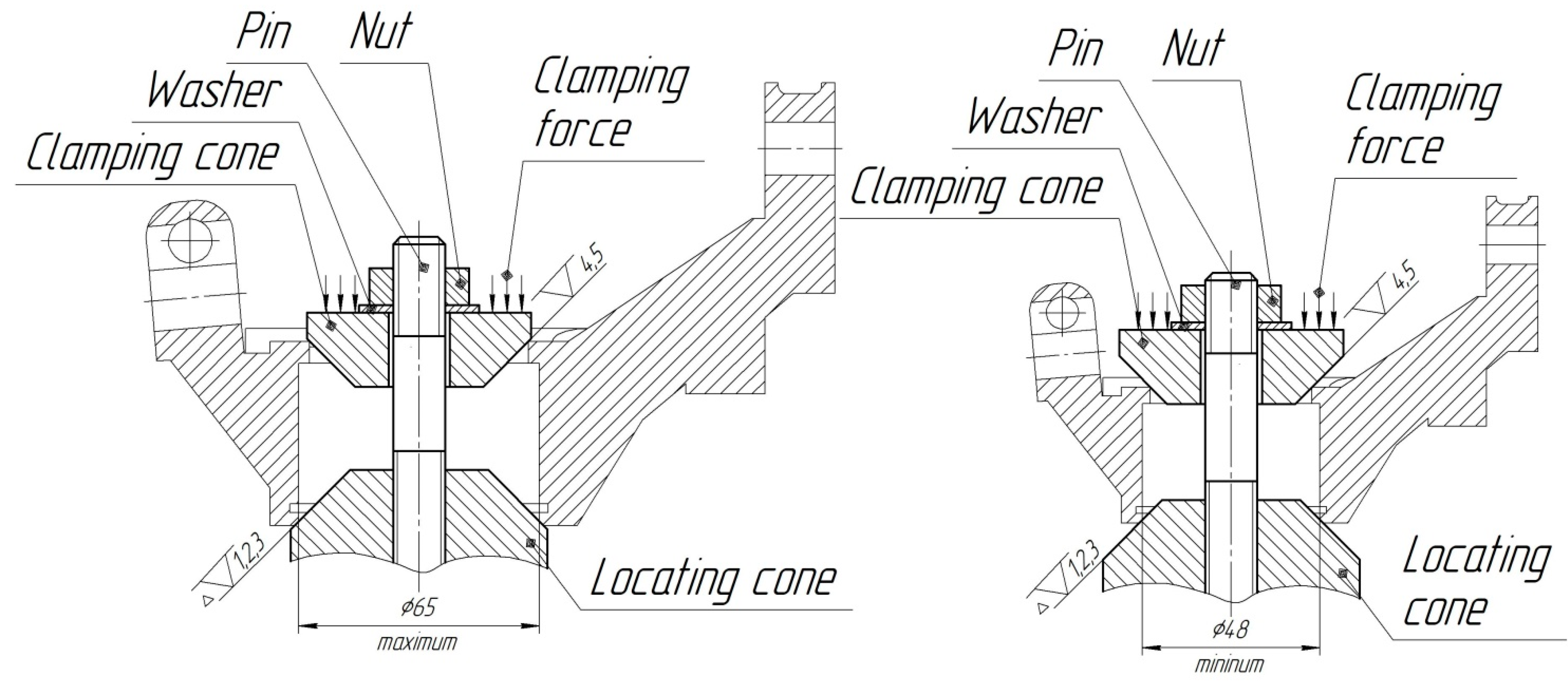
In previous studies [13,47] based on maximal stress and deflection evaluation by a physical measurement and FEM calculations, it was found that both of these parameters can be ensured within appropriate limits. In such a way, the proposed concept of incomplete orientation can be utilized for other complex form parts, for example, steering knuckles. The locating chart of the steering knuckles consists of locating points on the top and clamping points on the bottom (Figure 2).
This setup scheme provides only two surfaces for the workpiece bases for machining the holes on the heads’ surfaces on the steering knuckles’ shoulders. The surface of the central hole’s internal chamfer contacts the fixture’s external conical surface. The conical surface of the fixture centers the workpiece from displacement on the sides and downwards in the axial direction. Another annular surface of the ledge on the upper part of the workpiece in contact with the corresponding external conical surface of the fixture washer will center the workpiece against lateral displacement.
Thus, only one degree of freedom remains free, namely the workpiece’s rotation around the central hole’s axis. Clamping of the workpiece is carried out by evenly applying force to the annular surface of the opening of the outer ledge.
Thus, based on the location chart (Figure 2), the design of the flexible fixture that allows the implementation of this scheme is proposed. The proposed flexible fixture is intended for the setup of steering knuckles of different sizes in the range of diameters of the central hole 48–65 mm (Figure 2). The height of the central part of the steering knuckles between the end of the outer ledge and the end of the landing surface from the side of the central hole is 30–80 mm. The adjustment of the range is carried out by screwing the nut, which provides both a change in the distance between the supporting cones of the device and the clamping force for the workpiece between the cones. The lower and upper support cones are made with grooves for better clamping of the workpiece during machining and to prevent rotation.

2.1. Set Up of the Finite-Element Method Calculations

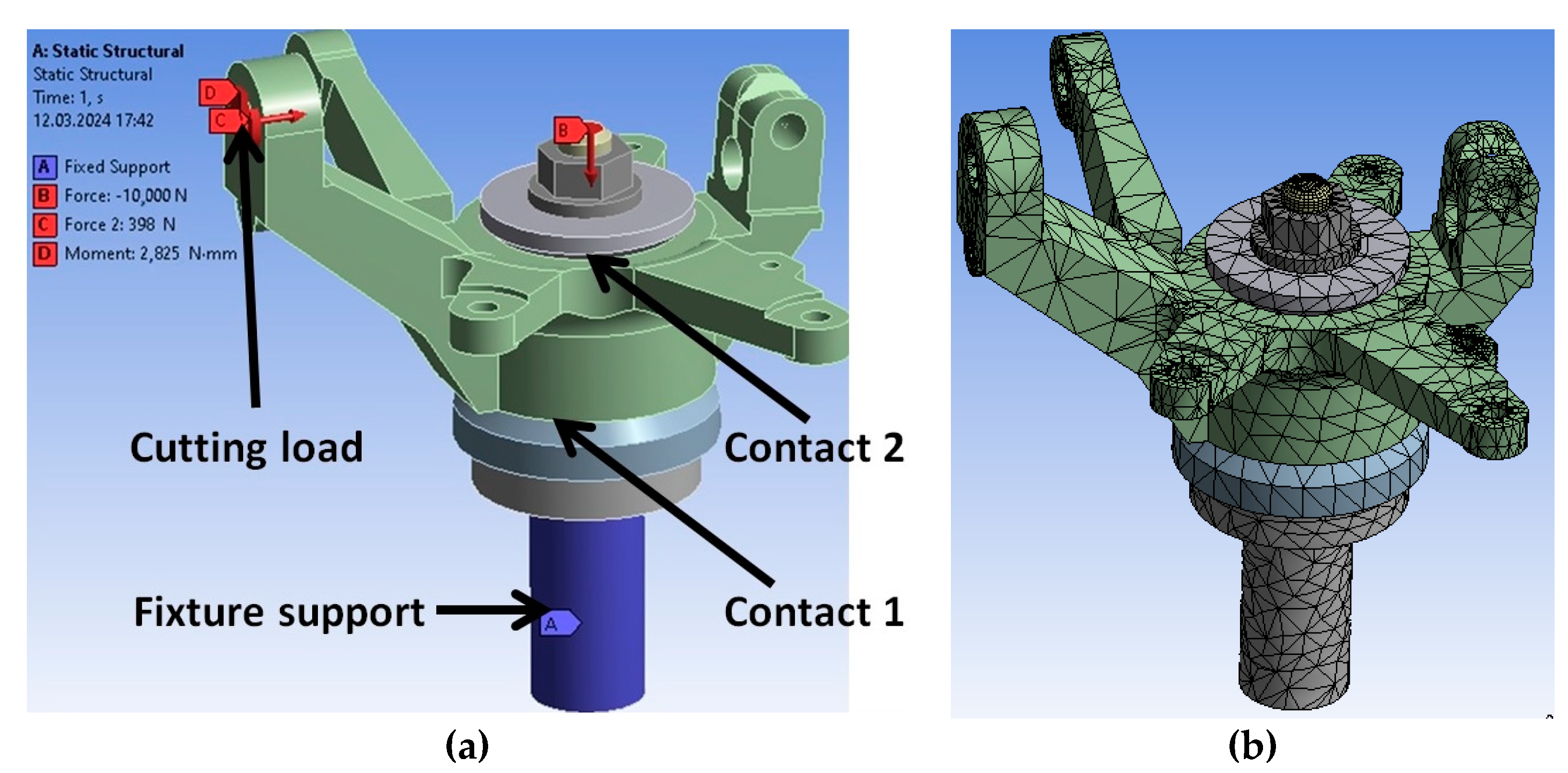
The improved flexible fixture was investigated using numerical simulation of the stress–strain state in the Static Structural module of the ANSYS ver. 19 Workbench Software (ANSYS, Inc., Canonsburg, PA, USA). At the same time, the deflection of the movement of the machined surfaces of the part (marked in red in Figure 3) relative to their initial position will also be evaluated.
During the FEM calculations, several boundary conditions were established (Table 3) [13,48].
Since the fixture will be operated under normal conditions and the type of production will be small and medium series, the recommended material for producing fixture parts is C45 steel, with the following chemical composition (Table 4) and mechanical properties (Table 5). These mechanical properties were considered in finite element modeling.
The calculation model also considers the Coulomb friction between the contact surfaces of the fixture parts with a coefficient of 0.1 since they have approximately the same roughness in the Ra 1.6–3.2 μm. The surface for location that was proposed in the current device is the shank (surface A in Figure 3). This type of fastening simulates its rigid clamping in the chuck on the machine table using the Fixture Support contact type, which assumes its complete immobility (in this case, the entire technological system is not investigated, but only the “fixture–workpiece” system).
During the FEM, the contact type of the other elements that have an abutment with each other, except for the contact of the lower support cone and the workpiece and the upper extraction cone and the workpiece, was set as bonded. The contacts of the lower support cone and the workpiece and the upper extraction cone and the workpiece were set as frictional, with the corresponding coefficient of friction (Table 3), because the surfaces of these cones have grooves that will help keep the workpiece in place due to force friction, which will be created by the normal force that will act when the nut is tightened [2]. A hexahedral finite element (SOLID 185) was used for calculating plasticity, hyperelasticity, stress stiffening, creep, large deflection, and significant strain capabilities, which properly fit the purposes of structural analysis [50].
Since the machined surface has no requirements for accuracy higher than 0.2 mm, the size of the finite-element mesh cannot be set less than this value. The mesh was generated using an additive software algorithm that automatically creates mesh for each surface depending on its design parameters and the basic settings of the ANSYS Workbench. As a result, the finite element mesh with 32,606 elements and 88,197 nodes was generated.
During FEM, loading forces and moments were applied to each surface one by one. First, the force was applied to one surface and the results were determined; then, the force was excluded from the calculation and another design force was applied to the other surface. Since CNC machines are usually single-spindle for greater versatility, they are typically machined with one tool. The value of cutting forces at different manufacturing steps varied within 25–398 N and torques 1105–2825 N · mm depending on the method and stage of machining. At the same time, an axial clamping force of 10,000 N was applied to the pin, which, with a pin strength class of 10.9, does not exceed 30% tensile strength.

2.2. Physical Measurement of Steering Knuckle Deflections

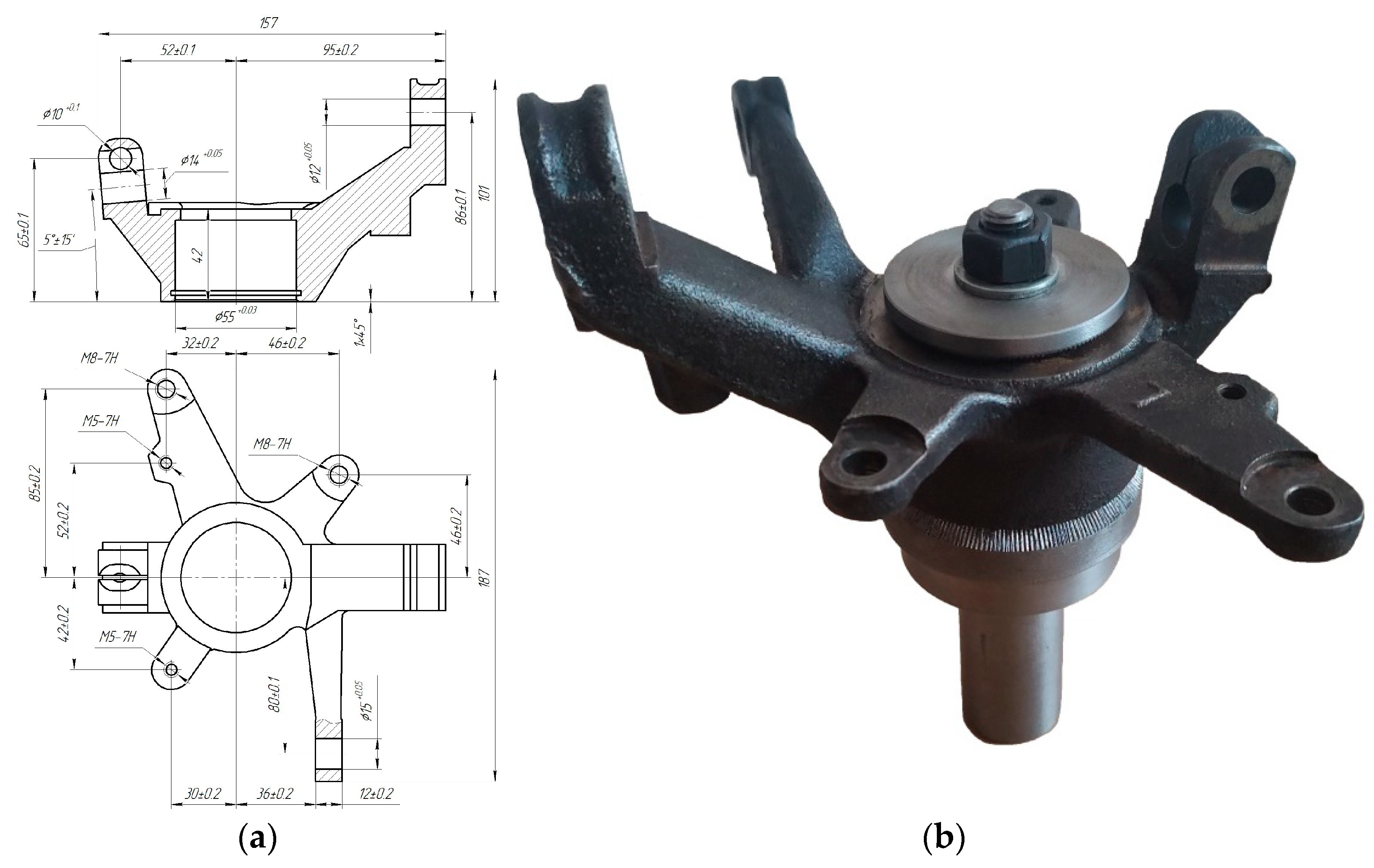
Experimental studies of the stress–strain state of the “fixture–workpiece” system are an intermediate stage between FEM and machining. A static experiment is also necessary to check the adequacy of the finite element analysis results by comparing them with the results of physical experiments. A fixture and its parts were manufactured based on 3D models of the fixture concept. Accuracy of fixture parts manufacturing and assembling was ensured according to the [51]. The steering knuckle of the BRP Can-AM Outlander L Max 500 DPS ATV was taken as an experimental sample (Figure 4).
Static loading of the part was conducted to investigate the value of part elements’ deflection under the force applied to specific machined areas. A custom test setup (Figure 5) was built to recreate the effect of a milling machine (Model 676P) load on the steering knuckle elements during machining [18].
The experimental setup (Figure 5) consists of the flexible fixture (1), which was clamped into a three-jaw chuck (2) mounted on the machine table. A force was loaded on the workpiece using a mandrel installed in the machine spindle (3). Additional interchangeable mandrels (4) were used on the steering knuckles to mount a mechanical dynamometer (5). This dynamometer is a calibrated spring device from Mohr and Federhaff (Mannheim, Germany) and has a known stiffness of 6 N/μm. The mandrel deflection was measured with a dial gauge with a graduation of 1 μm. The deflection of steering knuckle elements was measured with another dial gauge (6) (Shahe (5310-10) 0–12.7 mm, graduation of 1 μm) (Wenzhou Sanhe Measuring Instrument Co., Ltd., Wenzhou, China) installed on the opposite side of the loaded surface. The loading of elements was repeated three times.

3. Results

Analysis of the Finite Element Modeling

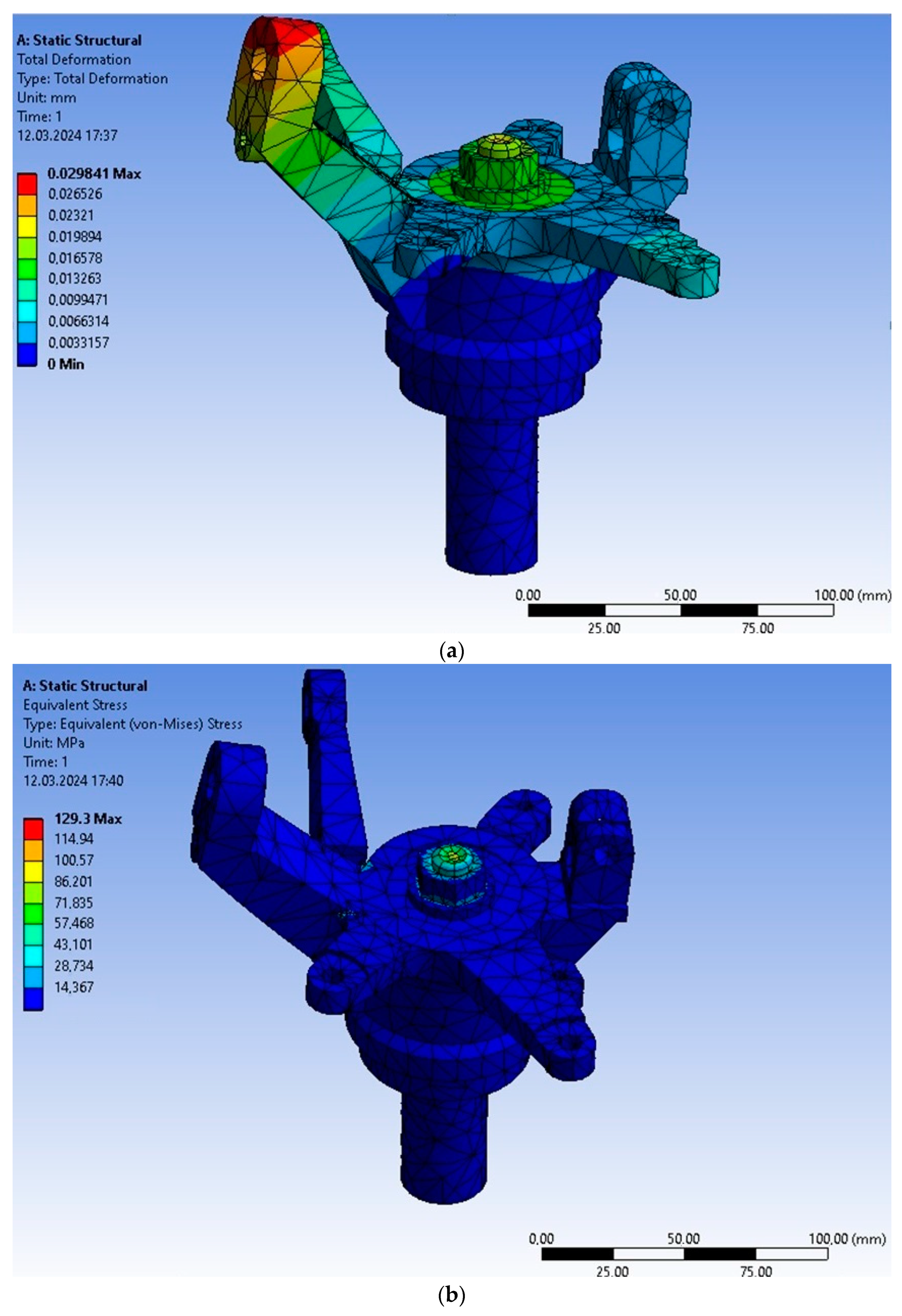
Setting these boundary conditions ensured proper setup fixture static loading with forces and torque. Load modeling was performed for the most loaded transitions and in those places where the fastening force was at the maximum distance from the machined surface (Figure 6). The values of the maximum equivalent stresses according to the IV hypothesis of Mises’s strength and maximum deflection of the elements of the “fixture–workpiece” system were obtained. The process of FEM was carried out similarly as in [13,48], the results of which showed their adequacy in confirmation by the results of physical experiments [47].
It can be seen from the results of the stress diagrams obtained in the “machine tool–workpiece” system (Figure 7b) that all the parts of the device and the workpiece are of uniform strength, except for the pin, where the maximum Mises stress is 129 MPa, because its stretching causes this as a result of applying the necessary fastening force to ensure reliable retention of the workpiece. The magnitudes of the general deformations (Figure 7a) indicate that the maximum displacements are expected at the processing point at the maximum distance from the attachment point and the fixture, respectively. However, simultaneously, the values of total displacements and displacements along the coordinate axes do not exceed a third of the size tolerance in the worst case of the FEM of a flexible fixture with an incomplete location for steering knuckles (deflection) (Figure 7a).
In general, the flexible fixture design based on the static analysis results looks relatively rigid, and the design features of the workpiece itself determine the maximum movements. However, there is no need for additional support because all loads are within permissible limits. This indicates that the process is not a force, but the difficulties in the manufacture and creation of special devices for almost each of the transitions of mechanical processing are determined not by the need to increase rigidity but only by the equipment’s capabilities at that time.
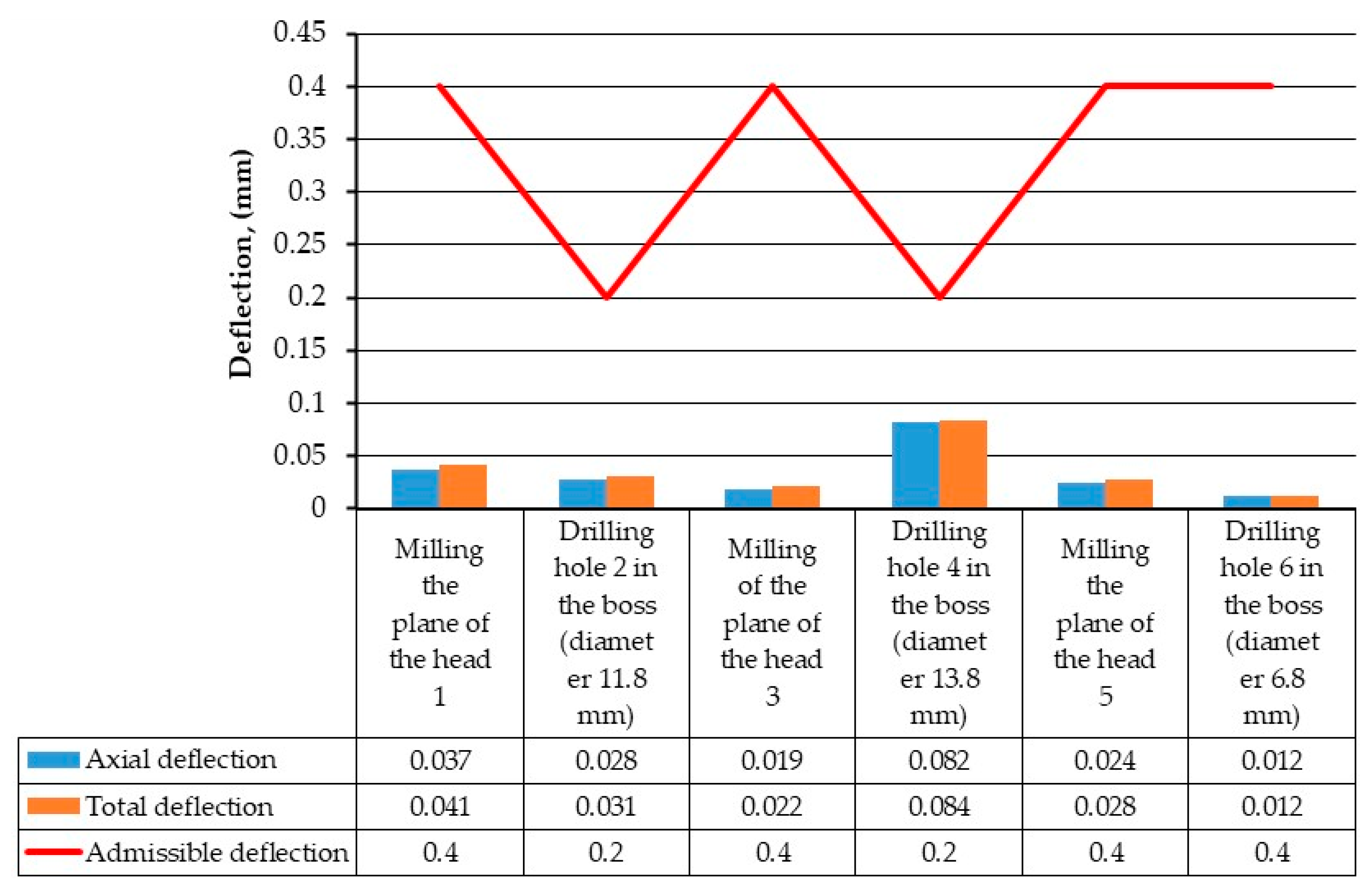
For loads at various manufacturing steps, the deflection of steering knuckles varied from 0.012 to 0.082 mm (Figure 8). Maximal axial deflection is characterized by a maximal axial load equivalent to the drilling of a 13.8 mm hole, which correlates to values of equivalent stress (Figure 9). Neither limits of admissible deflection nor admissible stress were broken under loads during static testing.
The results FEM of the main transitions of machining in the proposed flexible fixture showed that it is possible to achieve the required dimensional accuracy since the total deflection, as well as the values along the coordinate axes in the corresponding direction of the load, do not exceed the absolute limit values. Static stresses during the application of loads are also within acceptable limits according to the characteristics of the corresponding materials. The most stressed element of the system is the workpiece, where the arms of the steering knuckles are attached to the center of the part.
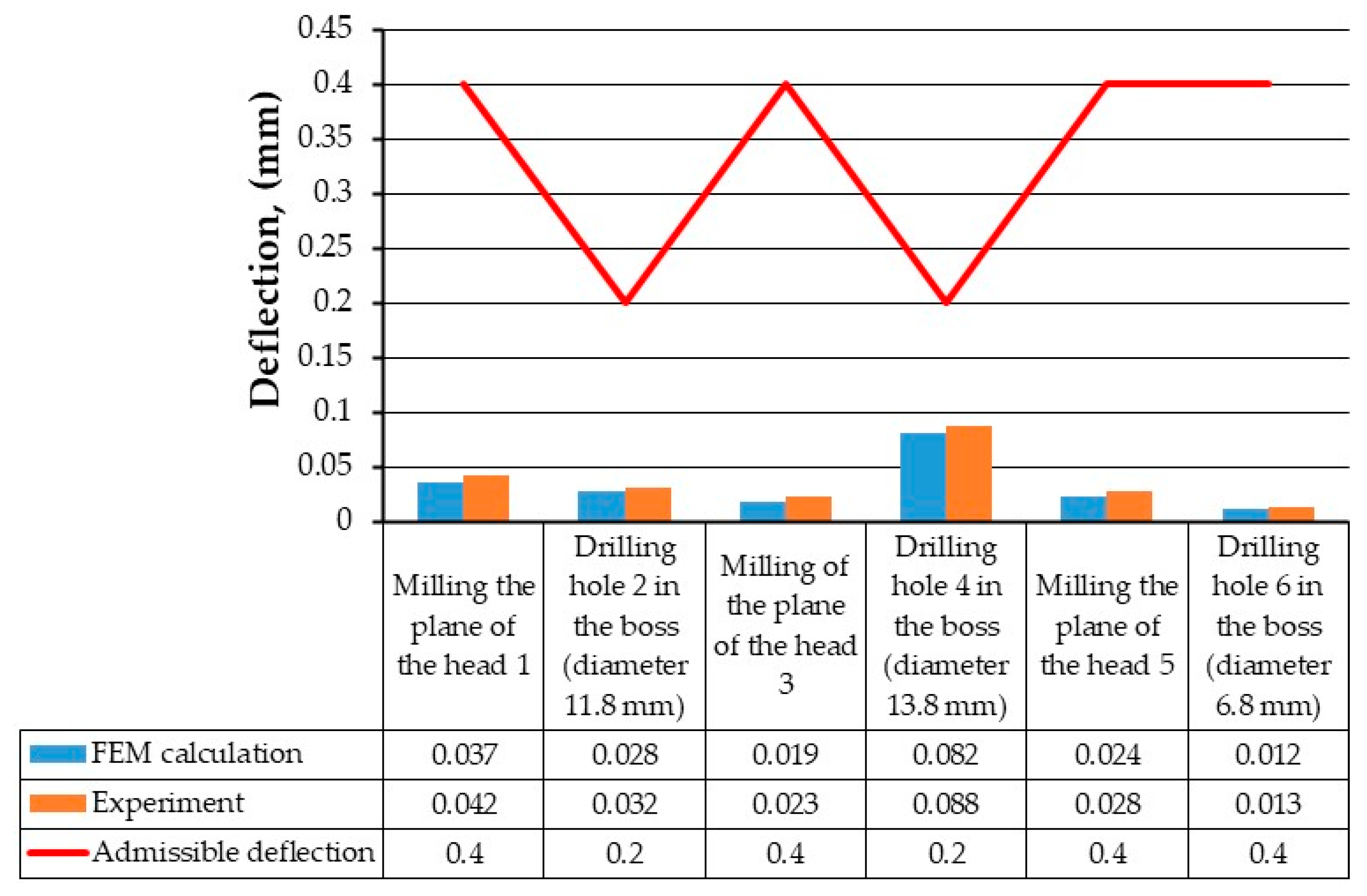
As a result, data on parts’ element deflection were collected and compared with the results of the FEM (Figure 10).
The values of deflection obtained experimentally do not exceed the allowed values, although they are higher than those obtained in FEM. The deviation of FEM and experimental results varied in the range of 6.8–17.3%, depending on the force load. The measurement uncertainty of the measuring tool and approximation of FEM results can explain this. However, in this case, the maximum relative error was less than 20%, despite the size of the margin to the allowed values of displacements being quite significant compared with the actual values of displacements at specific stages.

4. Discussion

Based on the results of FEM, the magnitudes of stresses and displacements in the proposed machine tool for processing parts of the steering knuckle type, using the principles of incomplete location, theoretically prove that the values of stresses in the structural elements do not exceed the permissible values according to the mechanical characteristics of the materials of the parts machine stand and workpiece. At the same time, the value of the maximum stresses at the transition with the most significant loads is 238 MPa, which is 2.5 times less than the permissible values. It was also established that the values of the total displacements of the processed surfaces in the proposed machine tool do not exceed the tolerances on the processed surfaces, and at the same time, there is a significant margin of accuracy for the performance of this technological operation because the displacement during processing is less than the permissible values from 2.4 to 30 times depending on specific transitions. According to the drawing, the values of movements along the coordinate axes along which the load was applied also do not exceed the allowable values.
From the experimental results, it can be seen that the design of the developed machined device for processing steering knuckles can provide the necessary accuracy of processing under static load since the magnitudes of displacements are, albeit, more significant than during numerical modeling by 1–6 μm, which in relative terms is 6.8–17.4% depending on the value of force load but still do not exceed the allowed values.
As for the comparison with the other authors research in this field, in particular, in the article [27], the authors present a multi-purpose approach to the synthesis of machine tools in a discrete area, where the criteria of efficiency are accuracy of basing, disconnection of reference points, deformation workpieces, degree and dispersion of reaction loads, and distance between contact points. This approach has been tested and proven effective for automating the reliable design selection of a machine tool for a prismatic workpiece. However, studies have not been conducted on other types of blanks. Experimental verification was also not performed.
The work [52] shows the development of new algorithms and machine learning with the possibility of using regression methods to create realistic, fast, and reliable equivalent models instead of modeling based on the finite element method. The paper also presents a new method that allows for the optimization of clamping concepts and the machine tool’s design with machine learning to help reduce errors during the production of parts and to obtain increased rigidity and accuracy of processing. However, as an example for modeling, a box-shaped workpiece with a stiffening rib in the middle was chosen, which cannot describe all types of interaction of the workpiece with device elements, and the simulation results were not confirmed experimentally.
Based on the results of theoretical and experimental studies, it was established that the proposed scientific approach to designing machine tools with incomplete location and ensuring the necessary stable position during processing due to clamping forces allows obtaining the specified accuracy. This proves the correctness of the working hypothesis [13,47] that devices with incomplete locations can ensure the specified processing accuracy, and this article is a logical continuation of previous research in this area and confirms this hypothesis experimentally.

5. Conclusions

In the current paper, the evaluation of static stiffness of steering knuckles in the flexible fixture was carried out using the finite element method and an experimental static tensile test. that the following was found out:
  • A flexible fixture with an incomplete location for steering knuckles provides sufficient accuracy at all transitions of a multi-purpose operation. Using FEM methods, it was evaluated that the maximum stresses of 238 MPa at the most loaded transition and the smallest part of the workpiece do not exceed the tensile strength, and at the same time, a margin of 2.5 times is preserved.
  • The proposed flexible fixture for machining parts steering knuckles can ensure the necessary accuracy under static loading since the movements do not exceed the permissible values on the corresponding surfaces according to the drawing. Although they are more significant than the results of FEM, in the worst case, by 17.4%, this allows to discuss the prospects of introducing fixtures with incomplete basing for machining other types of complexly shaped parts such as brackets, rockers, etc.
  • Validation of FEM and experimental results evaluated that a scientific approach to designing fixtures with incomplete locations allows obtaining the specified processing accuracy while ensuring the necessary stable position exclusively by clamping forces.
  • Further research will focus on the experimental determination of fixtures’ accuracy and stiffness characteristics of steering knuckles in dynamic mode during machining.

Author Contributions

Conceptualization, V.K. (Vitalii Kolesnyk), I.D. and A.N.; data curation, V.K. (Vitalii Kolesnyk), S.A. and S.L.; formal analysis, O.D., S.L. and R.T.; investigation, S.A., V.K. (Vitalii Kononovych) and R.T.; methodology, V.K. (Vitalii Kolesnyk) and M.K.; project administration, V.K. (Vitalii Kolesnyk) and A.D.; resources, I.D. and A.N.; software, S.A., V.K. (Vitalii Kononovych), O.D. and S.L.; supervision, I.D.; validation, A.N. and A.D.; visualization, V.K. (Vitalii Kononovych) and R.T.; writing—original draft, V.K. (Vitalii Kolesnyk), I.D., A.N., O.D. and A.D.; writing—review and editing, V.K. (Vitalii Kolesnyk) and M.K. All authors have read and agreed to the published version of the manuscript.

Funding

This research was funded by the Grant for Young Scientists of Ukraine of the Ministry of Education and Science of Ukraine (state registration number: 0124U000538): “Development of a smoke-automated control for the protection of evacuation vehicles and mobile posts”.

Data Availability Statement

Data are contained within the article.

Acknowledgments

The research was carried out within the project “Intensification of production processes and development of intelligent product quality control systems in smart manufacturing” (state registration number: 0122U200875, Ministry of Education and Science of Ukraine). Authors Vitalii Kolesnyk, Andrii Dovhopolov, Anna Neshta, and Ivan Dehtiarov would like to acknowledge the support of the National Scholarship Program of the Slovak Republic (NSP SAIA) in establishing cooperation with colleagues from the Slovak University of Technology in Bratislava during their scholarship stay.

Conflicts of Interest

The authors declare no conflicts of interest.

References

  1. Beno, M.; Zvoncan, M.; Kovác, M.; Peterka, J. Circular interpolation and positioning accuracy deviation measurement on five axis machine tools with different structures. Teh. Vjesn. 2013, 20, 479–484. [Google Scholar]
  2. Liu, C.H.; Wang, J.; Zhou, B.H.; Yu, J.B.; Zheng, Y.; Liu, J.F. Development of Fixture Layout Optimization for Thin-Walled Parts: A Review. Chin. J. Mech. Eng. 2024, 37, 17. [Google Scholar] [CrossRef]
  3. Gameros, A.A.; Axinte, D.; Siller, H.R.; Lowth, S.; Winton, P. Experimental and Numerical Study of a Fixturing System for Complex Geometry and Low Stiffness Components. J. Manuf. Sci. Eng.-Trans. ASME 2017, 139, 045001. [Google Scholar] [CrossRef]
  4. Zhang, G.Q.; Dai, Y.Q.; Lai, Z.H. A novel force-based two-dimensional tool centre error identification method in single-point diamond turning. Precis. Eng.-J. Int. Soc. Precis. Eng. Nanotechnol. 2021, 70, 92–109. [Google Scholar] [CrossRef]
  5. Yamnikov, A.S.; Danilenko, E.A. Influence of the Shape Error of Measuring Base on the Accuracy of Manufacturing Parts from Stamped Blanks. Meas. Tech. 2022, 65, 174–179. [Google Scholar] [CrossRef]
  6. Liu, S.L.; Afazov, S.; Becker, A.; Ratchev, S. Machining error prediction scheme aided smart fixture development in machining of a Ti6Al4V slender part. Proc. Inst. Mech. Eng. Part B-J. Eng. Manuf. 2023, 237, 1509–1517. [Google Scholar] [CrossRef]
  7. Fazil, A.; Ahmad, Z.; Hayat, K.; Sultan, T.; Ijaz, M.A.; Sohail, S.; Asad, M.; Djavanroodi, F. An experimental and numerical study on optimization of number and position of the clamps in sheet metals fixture. Mech. Adv. Mater. Struct. 2023, 1–11. [Google Scholar] [CrossRef]
  8. Parvaz, H.; Hosseini, S.V. Analysis of reaction forces in fixture locating points: An Analytical, numerical, and experimental study. Proc. Inst. Mech. Eng. Part B J. Eng. Manuf. 2024, 238, 809–822. [Google Scholar] [CrossRef]
  9. Sohrabifard, M.; Nategh, M.; Ghazavi, M. Evaluation, calibration, and modal analysis for determination of contact stiffness between workpiece and components of milling fixture. Proc. Inst. Mech. Eng. Part B J. Eng. Manuf. 2023, 237, 1819–1835. [Google Scholar] [CrossRef]
  10. Zhu, Z.J.; Zhao, C.Y. Angular error measurement of workpiece repositioning using a full-scale rotation detection method. Opt. Express 2023, 31, 4812–4825. [Google Scholar] [CrossRef]
  11. da Silva, W.T.A.; Peterka, J.; Vopat, T. Experimental Research on the Dynamic Stability of Internal Turning Tools for Long Overhangs. J. Manuf. Mater. Process. 2023, 7, 61. [Google Scholar] [CrossRef]
  12. Peterka, J.; Kuruc, M.; Kolesnyk, V.; Dehtiarov, I.; Moravcikova, J.; Vopat, T.; Pokorny, P.; Jurina, F.; Simna, V. Selected Aspects of Precision Machining on CNC Machine Tools. Machines 2023, 11, 946. [Google Scholar] [CrossRef]
  13. Ivanov, V.; Botko, F.; Dehtiarov, I.; Kocisko, M.; Evtuhov, A.; Pavlenko, I.; Trojanowska, J. Development of Flexible Fixtures with Incomplete Locating: Connecting Rods Machining Case Study. Machines 2022, 10, 493. [Google Scholar] [CrossRef]
  14. Fiedler, F.; Ehrenstein, J.; Höltgen, C.; Blondrath, A.; Schäper, L.; Göppert, A.; Schmitt, R. Jigs and fixtures in production: A systematic literature review. J. Manuf. Syst. 2024, 72, 373–405. [Google Scholar] [CrossRef]
  15. Wang, H.; Zhang, K.; Wu, D.; Yu, T.; Yu, J.; Liao, Y. Analysis and optimization of the machining fixture system stiffness for near-net-shaped aero-engine blade. Int. J. Adv. Manuf. Technol. 2021, 113, 3509–3523. [Google Scholar] [CrossRef]
  16. Shirinzadeh, B. Flexible fixturing for workpiece positioning and constraining. Assem. Autom. 2002, 22, 112–120. [Google Scholar] [CrossRef]
  17. Feng, Q.; Maier, W.; Stehle, T.; Möhring, H.C. Optimization of a clamping concept based on machine learning. Prod. Eng.-Res. Dev. 2022, 16, 9–22. [Google Scholar] [CrossRef]
  18. Park, J.W.; Park, J.; Kim, H.; Kim, N.; Kim, D.Y. Assembly Part Positioning on Transformable Pin Array Fixture by Active Pin Maximization and Joining Point Alignment. IEEE Trans. Autom. Sci. Eng. 2022, 19, 1047–1057. [Google Scholar] [CrossRef]
  19. Hao, Q.L.; Yang, Q. A self-adaptive auxiliary fixture for deformation control in blade machining. Int. J. Adv. Manuf. Technol. 2020, 111, 1415–1423. [Google Scholar] [CrossRef]
  20. Arslane, M.; Slamani, M.; Chatelain, J.F. Development and validation of a machining fixture for complex-shaped components based on Pluckerian matrix approach and SDT concept. Int. J. Adv. Manuf. Technol. 2021, 114, 1697–1716. [Google Scholar] [CrossRef]
  21. Zheng, Y.; Hou, Z.; Rong, Y. The study of fixture stiffness—Part II: Contact stiffness identification between fixture components. Int. J. Adv. Manuf. Technol. 2008, 38, 19–31. [Google Scholar] [CrossRef]
  22. Sohrabifard, M.; Nategh, M.J. Investigation of the stability and contact stiffness of workpiece inside fixture in different machining conditions. Proc. Inst. Mech. Eng. Part C J. Mech. Eng. Sci. 2023, 237, 4739–4758. [Google Scholar] [CrossRef]
  23. Zheng, Y.; Rong, Y.; Hou, Z. The study of fixture stiffness part I: A Finite element analysis for stiffness of fixture units. Int. J. Adv. Manuf. Technol. 2008, 36, 865–876. [Google Scholar] [CrossRef]
  24. Ivanov, V.; Dehtiarov, I.; Pavlenko, I.; Liaposhchenko, O.; Zaloga, V. Parametric Optimization of Fixtures for Multiaxis Machining of Parts. In Advances in Manufacturing Ii, Vol 2—Production Engineering and Management; Springer: Berlin/Heidelberg, Germany, 2019; pp. 335–347. [Google Scholar] [CrossRef]
  25. Liu, J.F.; Du, X.M.; Zhou, H.G.; Liu, X.J.; Li, L.; Feng, F. A digital twin-based approach for dynamic clamping and positioning of the flexible tooling system. Procedia CIRP 2019, 80, 746–749. [Google Scholar] [CrossRef]
  26. Toro, J.V.; Wiberg, A.; Tarkian, M. Application of optimized convolutional neural network to fixture layout in automotive parts. Int. J. Adv. Manuf. Technol. 2023, 126, 339–353. [Google Scholar] [CrossRef]
  27. Alshameri, T.; Ding, H.; Dong, Y.D.; Yiheng, Z.; Hui, J.; Maqram, A. Multi-Objective Approach to Automated Fixture Synthesis Incorporating Deep Neural Network for Deformation Evaluation. Robot. Comput.-Integr. Manuf. 2023, 84, 102579. [Google Scholar] [CrossRef]
  28. Guo, H.N.; Li, Y.G.; Liu, C.Q.; Ni, Y.; Tang, K. A Deformation Force Monitoring Method for Aero-Engine Casing Machining Based on Deep Autoregressive Network and Kalman Filter. Appl. Sci. 2022, 12, 7014. [Google Scholar] [CrossRef]
  29. Li, E.M.; Zhou, J.T.; Yang, C.S.; Wang, M.W.; Zhang, S.S. Clamping force prediction based on deep spatio-temporal network for machining process of deformable parts. Sci. Rep. 2023, 13, 7012. [Google Scholar] [CrossRef]
  30. Mirzendehdel, A.M.; Behandish, M.; Nelaturi, S. Topology optimization with accessibility constraint for multi-axis machining. Comput.-Aided Des. 2020, 122, 102825. [Google Scholar] [CrossRef]
  31. Mirzendehdel, A.M.; Behandish, M.; Nelaturi, S. Topology Optimization for Manufacturing with Accessible Support Structures. Comput.-Aided Des. 2022, 142, 103117. [Google Scholar] [CrossRef]
  32. Han, X.B.; Feng, W.D. Error model of a precision two-dimensional fixture. Int. J. Adv. Manuf. Technol. 2023, 124, 4033–4043. [Google Scholar] [CrossRef]
  33. Cheng, S.; Tan, G.Q. Intelligent vehicle inspection tool design based on freeman chain code for automatic annotation of 3D models. Scalable Comput.-Pract. Exp. 2023, 24, 769–782. [Google Scholar] [CrossRef]
  34. Li, E.M.; Zhou, J.T.; Yang, C.S.; Zhao, J.H.; Li, Z.Y.; Zhang, S.S.; Wang, M.W. Part machining deformation prediction based on spatial-temporal correlation learning of geometry and cutting loads. J. Manuf. Process. 2023, 92, 397–411. [Google Scholar] [CrossRef]
  35. Dovhopolov, A.; Nekrasov, S.; Zhyhylii, D.; Savchenko, Y.; Stupin, B. Modeling of a Stress-Strain State of Detachable Connection in Details of Reinforced Composite Materials with CEA Method. Stroj. Časopis-J. Mech. Eng. 2020, 70, 17–28. [Google Scholar] [CrossRef]
  36. Li, Y.; Li, Y.H.; Ma, X.P.; Zhang, X.H.; Fu, D.Y.; Yan, Q.T. Study on Welding Deformation and Optimization of Fixture Scheme for Thin-Walled Flame Cylinder. Materials 2022, 15, 6418. [Google Scholar] [CrossRef] [PubMed]
  37. Meng, S.; Zheng, L.Y.; Fan, W.; Wang, X.; Zhou, J. Intelligent layout optimization of reconfigurable flexible fixture for assembling multiple aircraft panels. Int. J. Adv. Manuf. Technol. 2023, 126, 1261–1278. [Google Scholar] [CrossRef]
  38. Du, X.M.; Liu, S.; Jin, S. Distribution analysis of deterministic clamping and positioning error for machining of ring-shaped workpieces considering alignment uncertainty. Int. J. Adv. Manuf. Technol. 2024, 131, 3921–3936. [Google Scholar] [CrossRef]
  39. Qazani, M.R.C.; Parvaz, H.; Pedrammehr, S. Optimization of fixture locating layout design using comprehensive optimized machine learning. Int. J. Adv. Manuf. Technol. 2022, 122, 2701–2717. [Google Scholar] [CrossRef]
  40. Rex, F.M.T.; Hariharasakthisudhan, P.; Andrews, A.; Abraham, B.P. Optimization of flexible fixture layout to improve form quality using parametric finite element model and mixed discrete-integer genetic algorithm. Proc. Inst. Mech. Eng. Part C-J. Eng. Mech. Eng. Sci. 2022, 236, 16–29. [Google Scholar] [CrossRef]
  41. Weicheng, G.; Yong, Z.; Xiaohui, J.; Ning, Y.; Kun, W.; Xiao, L. Improvement of stiffness during milling thin-walled workpiece based on mechanical/magnetorheological composite clamping. J. Manuf. Process. 2021, 68, 1047–1059. [Google Scholar] [CrossRef]
  42. Nekrasov, S.; Zhyhylii, D.; Dovhopolov, A.; Karatas, M.A. Research on the manufacture and strength of the innovative joint of FRP machine parts. J. Manuf. Process. 2021, 72, 338–349. [Google Scholar] [CrossRef]
  43. Buransky, I.; Bracik, M.; Simna, V.; Vopat, T. Influence of end millvariable pitch on surface quality of aluminium thin-walled parts. MM Sci. J. 2018, 2018, 2552–2557. [Google Scholar] [CrossRef]
  44. Pawar, U.; Chavan, S.G.; Bhole, K.S.; Rathod, M.; Bhole, D. Computer aided approach for case specific design of fixture for slot milling process. Int. J. Interact. Des. Manuf.-IJIDeM 2023, 1–11. [Google Scholar] [CrossRef]
  45. Byun, S.H.; Seo, J.H.; Cho, R.Y.; Yi, S.M.; Kim, L.K.; Han, H.S.; On, S.W.; Kim, W.H.; An, H.W.; Yang, B.E. Finite Element Analysis of a New Non-Engaging Abutment System for Three-Unit Implant-Supported Fixed Dental Prostheses. Bioengineering 2022, 9, 483. [Google Scholar] [CrossRef] [PubMed]
  46. Technical Card Steel 41Cr4; Quenching and Tempering Steel; Ovako AB: Stockholm, Sweden.
  47. Dehtiarov, I.; Neshta, A.; Kosov, I.; Klok, Y. Experimental research of the rigidity of fixtures with incomplete location for connecting rod type parts. Tech. Sci. Technol. 2022, 3, 15–26. [Google Scholar] [CrossRef]
  48. Ivanov, V.; Dehtiarov, I.; Evtuhov, A.; Pavlenko, I.; Ruban, A. Multiaxis Machining of Fork-Type Parts: Fixture Design and Numerical Simulation. In Lecture Notes in Networks and Systems; Springer: Cham, Germany, 2021; Volume 223, pp. 142–152. [Google Scholar]
  49. Material Datasheet C45; Murray Steel Products: Middlesbrough, UK.
  50. ANSYS Mechanical User’s Guide; ANSYS, Inc.: Canonsburg, PA, USA, 2013; p. 1858.
  51. 80-ENG-D-413; Checking Fixture—Gauge Standard. ABC Technologies: Southfield, MI, USA, 2020.
  52. Ding, G.Z.; Wang, Y.F.; Yuan, S.M.; Lin, L.; Zhao, Z.C. Research on Rapid and Accurate Fixture Design for Non-Intervention Machining of Complex Parts. Metals 2022, 12, 1174. [Google Scholar] [CrossRef]
Figure 1. Examples of steering knuckles: (a) ATV Segway Snarler AT6 (Segway Technology Co., Ltd., Bedford, VA, USA); (b) automobile KIA Sportage (Kia Motors Corporation, Seul, Republic of Korea); (c) automobile Chery Tiggo (Chery Automobile, Anhui, China); and (d) ATV BRP Can-AM Outlander L Max 500 DPS (Bombardier Recreational Products, Valcourt, QC, Canada).
Machines 12 00405 g001
Figure 2. The locating chart in a flexible fixture for steering knuckles for different sizes.
Machines 12 00405 g002
Figure 3. Set up of boundary conditions (a) and finite element mesh (b) of steering knuckles.
Machines 12 00405 g003
Figure 4. Drawing of steering knuckles BRP Can-AM Outlander L Max 500 DPS (Bombardier Recreational Products, Valcourt, QC, Canada) (a) and an experimental sample of an improved fixture with an incomplete location for machining steering knuckles (b).
Machines 12 00405 g004
Figure 5. Experimental setup for determining the displacements of the fixture elements for machining steering knuckles: (a) in the vertical plane and (b) in the horizontal plane.
Machines 12 00405 g005
Figure 6. Numbering of the machined surfaces of the steering knuckles.
Machines 12 00405 g006
Figure 7. Graph of steering knuckles deflection (a) and stress state (b) when loading hole 2.
Machines 12 00405 g007
Figure 8. Results of the FEM of a flexible fixture with an incomplete location for steering knuckles (deflection).
Machines 12 00405 g008
Figure 9. Results of the FEM of a dedicated fixture with an incomplete location of steering knuckles (equivalent stress).
Machines 12 00405 g009
Figure 10. Comparison of FEM calculations and experimental measurement of part element deflection.
Machines 12 00405 g010
Table 1. Chemical composition of Steel 41Cr4 ISO683-2:2018 by weight [46].
C, %P, %S, %Si, %Mn, %Cr, %Cu, %Ni, %Fe, %
0.410.0350.040.20.80.250.40.2597.615
Table 2. Mechanical properties of Steel 41Cr4 ISO683-2:2018 [46].
Young’s Modulus, GPaPoisson’s RatioDensity,
kg/m3
Tensile Strength, MPaThe Ultimate Strength of the Compression, MPaYield Strength, MPaHardness, (HRC)
2000.3785095095072645
Table 3. Contact conditions of improved fixtures for steering knuckles.
Parameters of Implemented Contact Groups
ContactContact SurfaceType of Contacting SurfaceFriction Coefficient
1working surface of the bottom cone/cone surface of the steering knucklescorrugated/machined0.7 [13]
2the working surface of the top cone/cylindrical surface of the top face of the steering knucklescorrugated/unmachined0.3 [13]
Table 4. Chemical composition of Steel C45 BS EN 10083 by weight [49].
C, %P, %S, %Mn, %Cr, %Fe, %
0.450.0250.0350.80.598.19
Table 5. Mechanical properties of Steel C45 for the workpiece and fixture elements [49].
Young’s Modulus, GPaPoisson’s RatioDensity,
kg/m3
Tensile Strength, MPaThe Ultimate Strength of the Compression, MPaYield Strength, MPaHardness, (HRC)
2000.3785093293278433
Disclaimer/Publisher’s Note: The statements, opinions and data contained in all publications are solely those of the individual author(s) and contributor(s) and not of MDPI and/or the editor(s). MDPI and/or the editor(s) disclaim responsibility for any injury to people or property resulting from any ideas, methods, instructions or products referred to in the content.