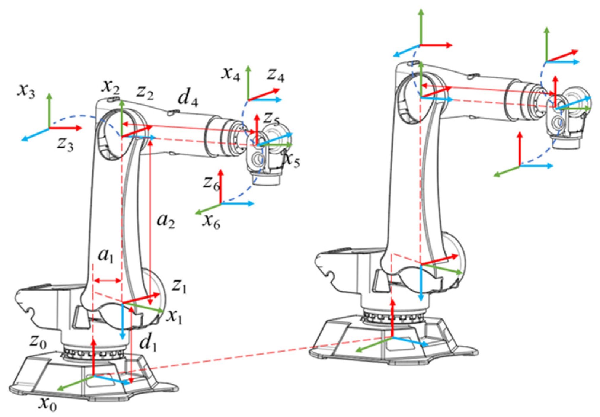
Figure 1.
DH coordinate systems of dual-arm robot.
Figure 1.
DH coordinate systems of dual-arm robot.
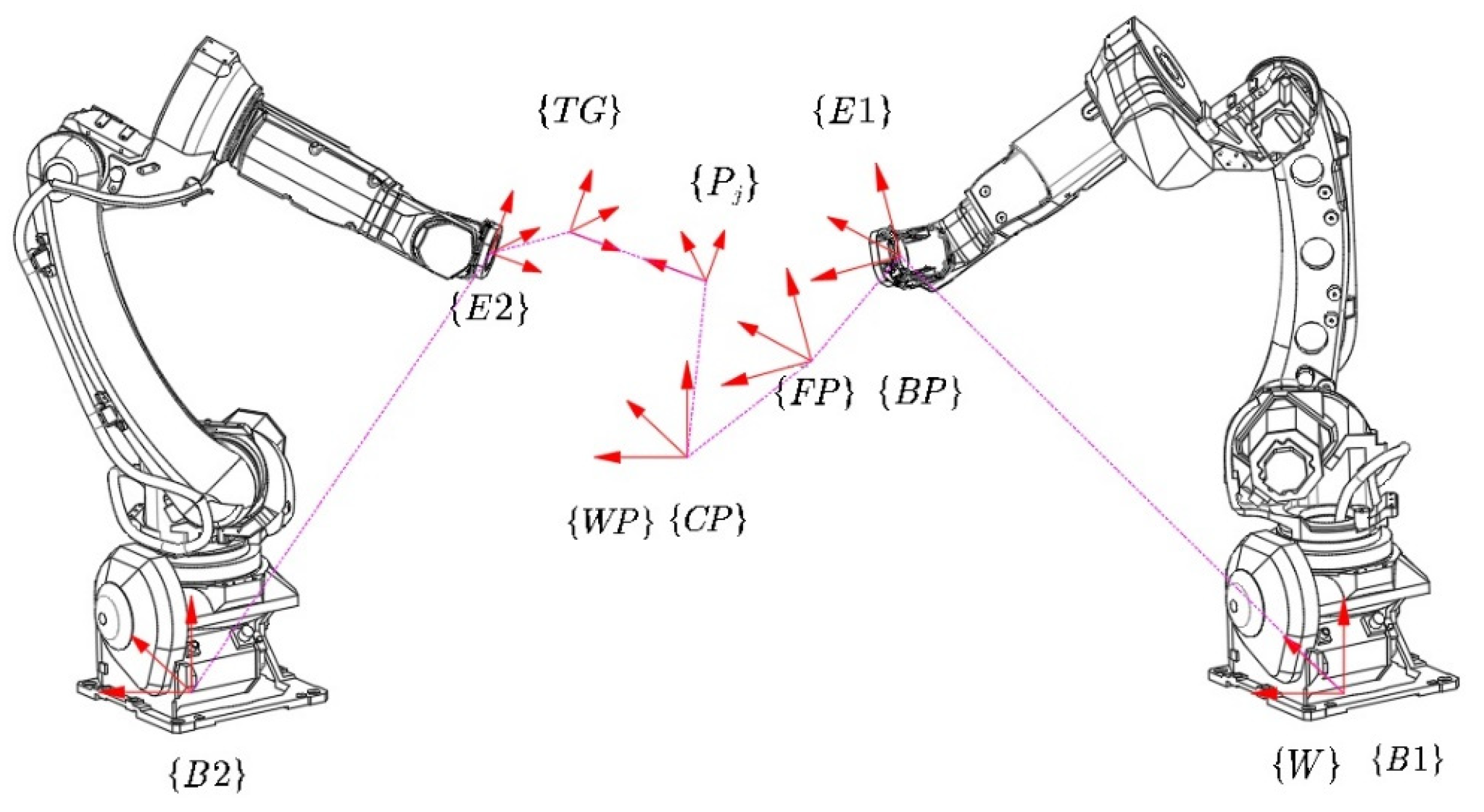
Figure 2.
The coordinate systems’ relationship of dual-arm robots.
Figure 2.
The coordinate systems’ relationship of dual-arm robots.
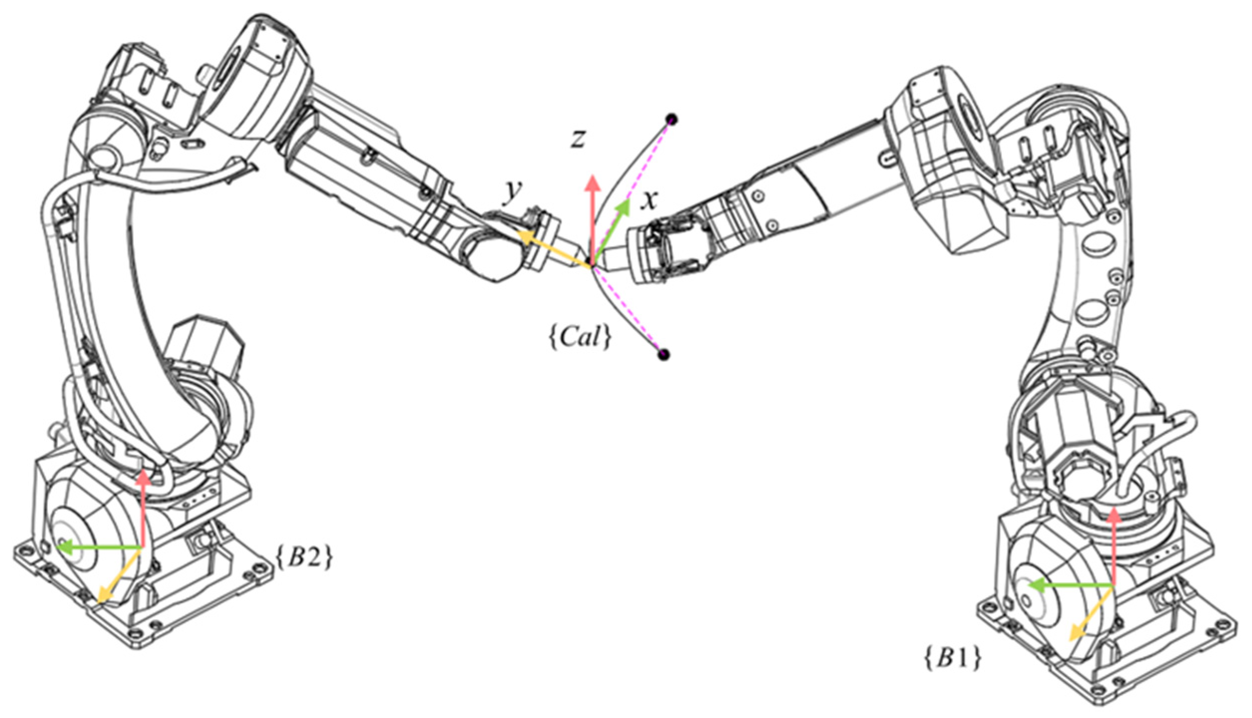
Figure 3.
Calibration of the base coordinate system for dual-arm robots.
Figure 3.
Calibration of the base coordinate system for dual-arm robots.
Figure 4.
The workpiece and its three-dimensional model: (a) workpiece; (b) three-dimensional model of workpiece.
Figure 4.
The workpiece and its three-dimensional model: (a) workpiece; (b) three-dimensional model of workpiece.
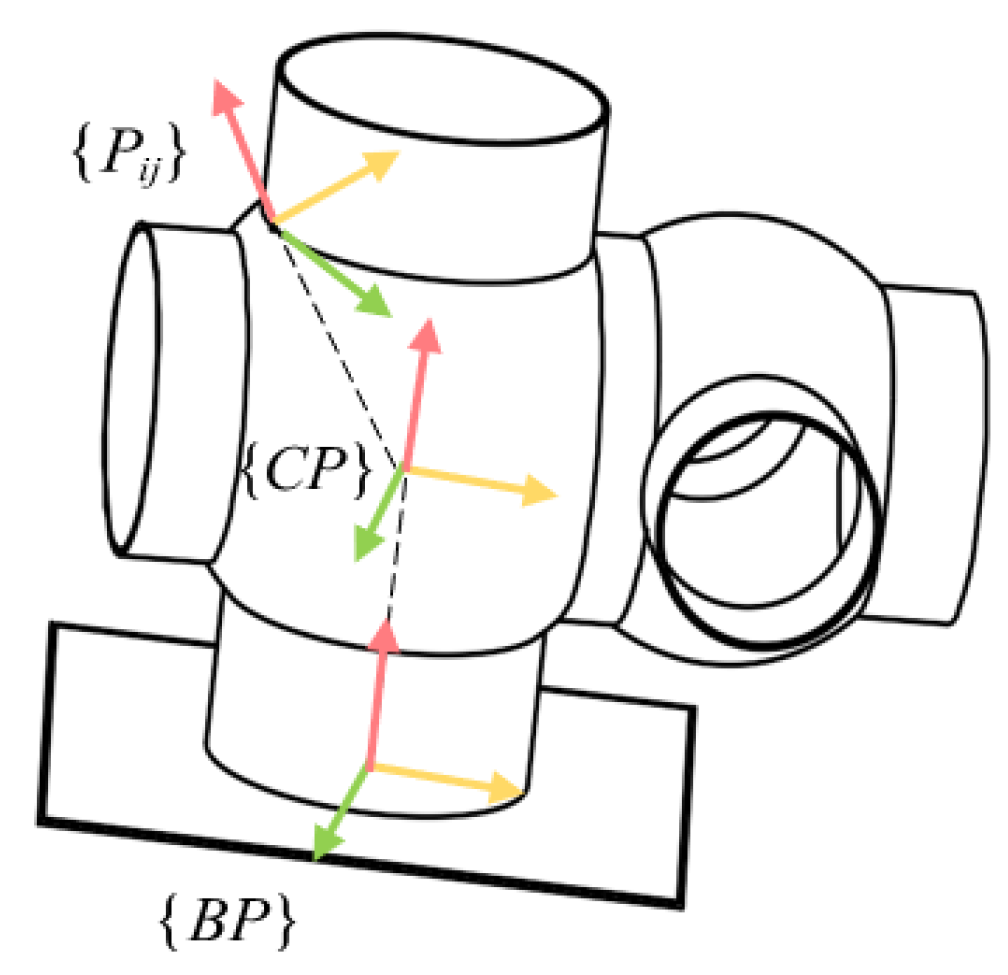
Figure 5.
Workpiece coordinate systems.
Figure 5.
Workpiece coordinate systems.
Figure 6.
Schematic diagram of arc trajectory.
Figure 6.
Schematic diagram of arc trajectory.
Figure 7.
Schematic diagram of intersecting pipe trajectory.
Figure 7.
Schematic diagram of intersecting pipe trajectory.
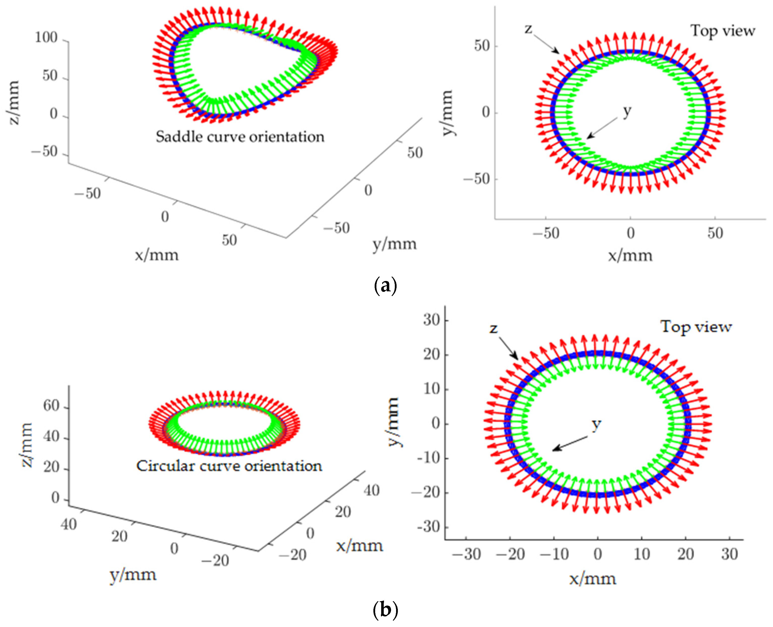
Figure 8.
Discretization of curve trajectory position and attitude: (a) saddle curve pose interpolation; (b) arc curve pose interpolation.
Figure 8.
Discretization of curve trajectory position and attitude: (a) saddle curve pose interpolation; (b) arc curve pose interpolation.
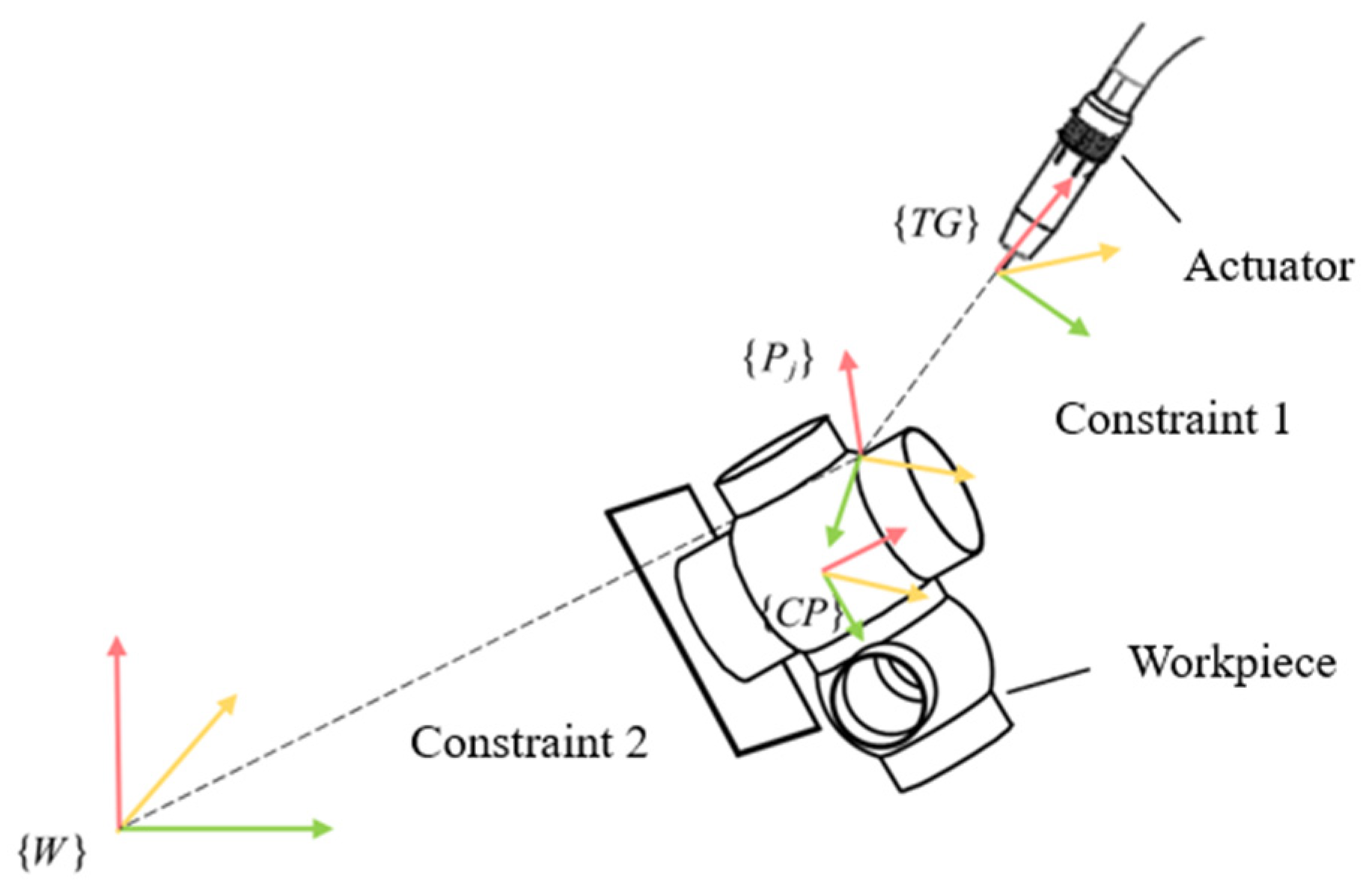
Figure 9.
Illustration of constraints.
Figure 9.
Illustration of constraints.
Figure 10.
Flowchart of the dual-arm motion cooperative planning method.
Figure 10.
Flowchart of the dual-arm motion cooperative planning method.
Figure 11.
Logic block diagram of the dual-arm robot motion cooperative program.
Figure 11.
Logic block diagram of the dual-arm robot motion cooperative program.
Figure 12.
Dual-arm motion collaboration process (Scenario 1): (a) zero pose; (b) docking point; (c) move forward by 1/2 track; (d) move backward by 1/2 track.
Figure 12.
Dual-arm motion collaboration process (Scenario 1): (a) zero pose; (b) docking point; (c) move forward by 1/2 track; (d) move backward by 1/2 track.
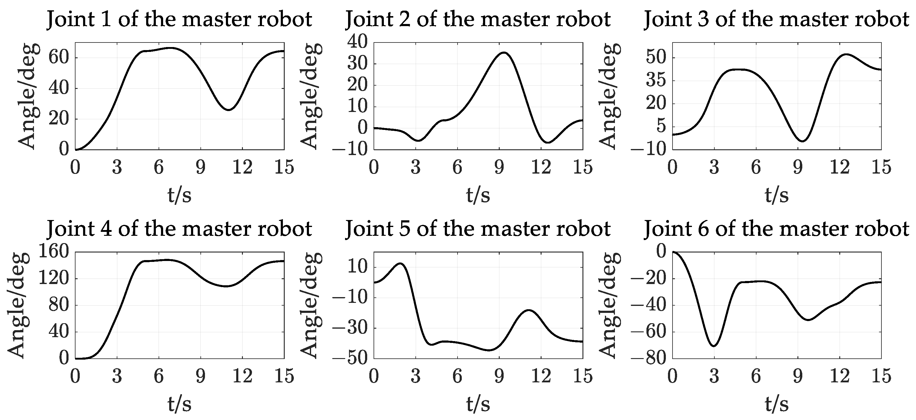
Figure 13.
Master robot joint angle change curve.
Figure 13.
Master robot joint angle change curve.
Figure 14.
Slave robot joint angle change curve.
Figure 14.
Slave robot joint angle change curve.
Figure 15.
Dual-arm coordinated motion process (Scenario 2): (a) zero pose; (b) docking point; (c) movement to 1/4 circle trajectory; (d) movement to 3/4 circle trajectory.
Figure 15.
Dual-arm coordinated motion process (Scenario 2): (a) zero pose; (b) docking point; (c) movement to 1/4 circle trajectory; (d) movement to 3/4 circle trajectory.
Figure 16.
Motion process of the actuator and workpiece in a circular trajectory.
Figure 16.
Motion process of the actuator and workpiece in a circular trajectory.
Figure 17.
Joint angle change curves of the master robot.
Figure 17.
Joint angle change curves of the master robot.
Figure 18.
Joint angle change curves of the slave robot.
Figure 18.
Joint angle change curves of the slave robot.
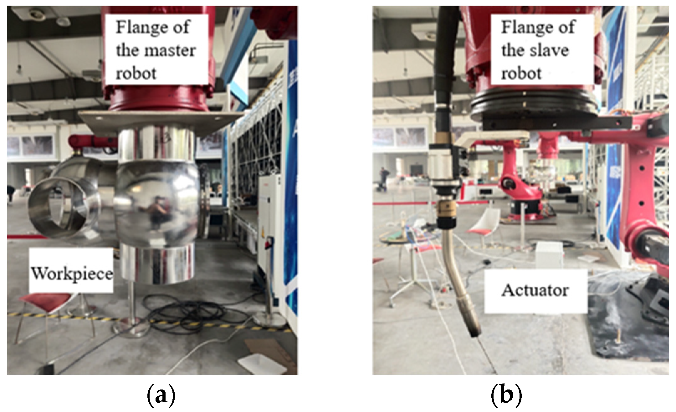
Figure 19.
Schematic diagram of workpiece and actuator installation: (a) workpiece; (b) actuator.
Figure 19.
Schematic diagram of workpiece and actuator installation: (a) workpiece; (b) actuator.
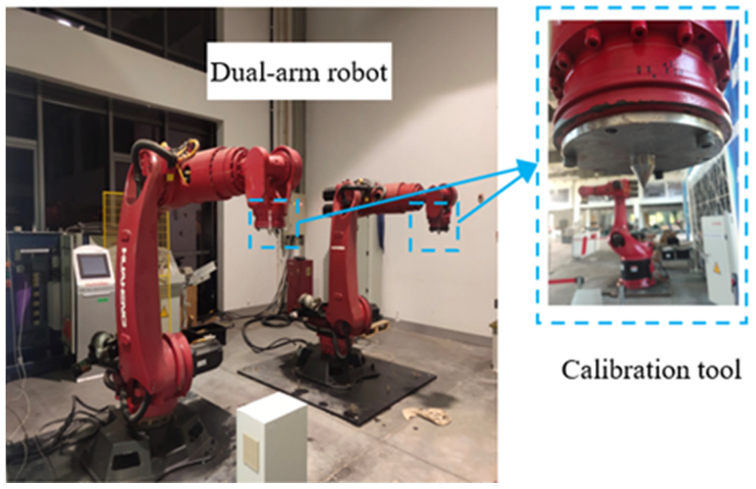
Figure 20.
Dual-arm robot and calibration tools.
Figure 20.
Dual-arm robot and calibration tools.
Figure 21.
Point-to-point calibration experiment for dual-arm robots: (a) spatial first encounter; (b) spatial second encounter; (c) spatial third encounter; (d) close-up view of first encounter; (e) close-up view of second encounter; (f) close-up view of third encounter.
Figure 21.
Point-to-point calibration experiment for dual-arm robots: (a) spatial first encounter; (b) spatial second encounter; (c) spatial third encounter; (d) close-up view of first encounter; (e) close-up view of second encounter; (f) close-up view of third encounter.
Figure 22.
The key nodes of dual-arm motion coordination trajectory: (a) zero pose; (b) docking point; (c) forward 1/2 trajectory; (d) directional 1/2 trajectory.
Figure 22.
The key nodes of dual-arm motion coordination trajectory: (a) zero pose; (b) docking point; (c) forward 1/2 trajectory; (d) directional 1/2 trajectory.
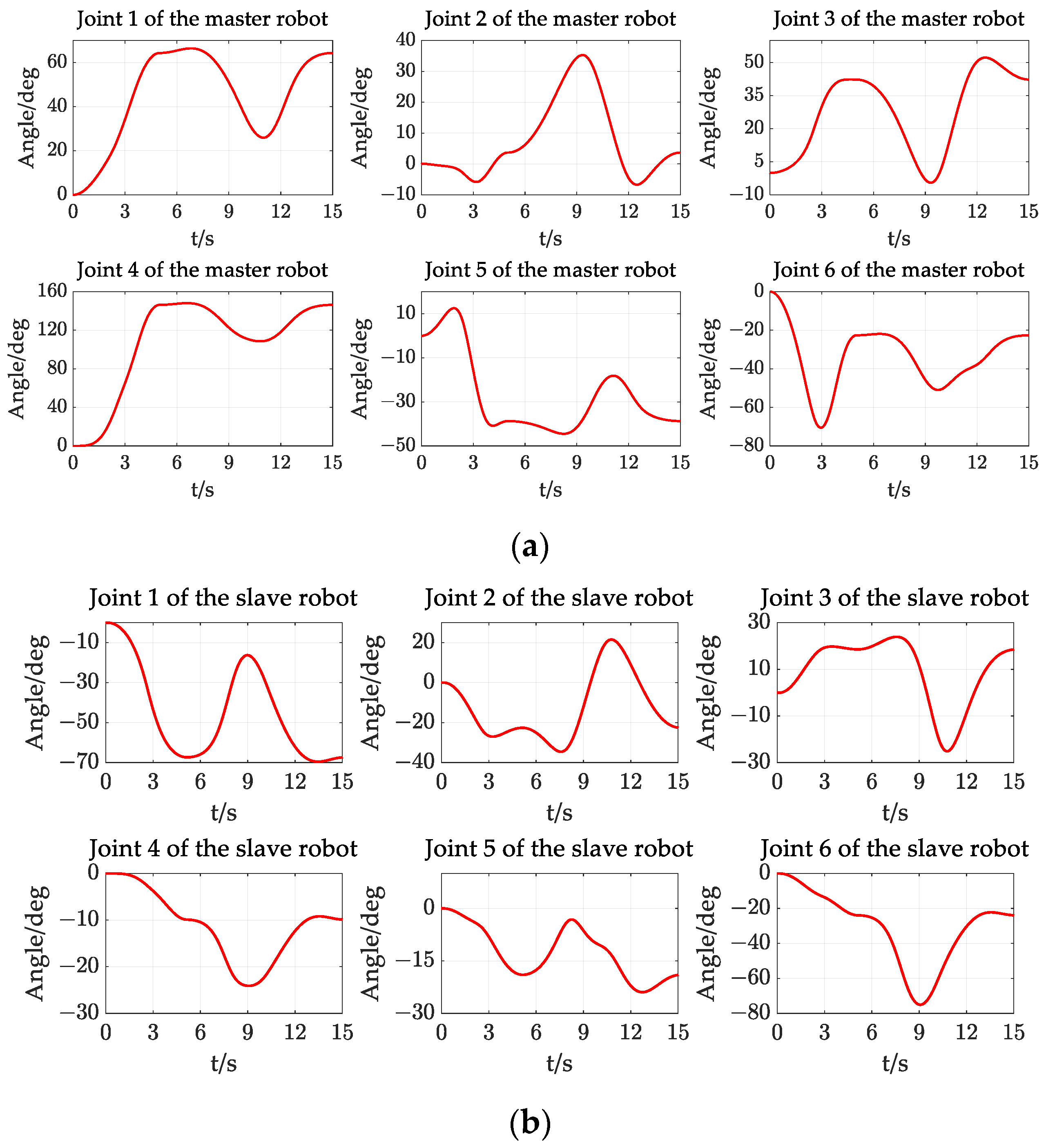
Figure 23.
The joint-angle change curves of the dual-arm robot experiment (Scenario 1): (a) the joint-angle change curves of the master robot; (b) the joint-angle change curves of the slave robot.
Figure 23.
The joint-angle change curves of the dual-arm robot experiment (Scenario 1): (a) the joint-angle change curves of the master robot; (b) the joint-angle change curves of the slave robot.
Figure 24.
Velocity change curves of a dual-arm robot (scenario 1): (a) joint angular velocity curves of the master robot; (b) joint angular velocity curves of the slave robot.
Figure 24.
Velocity change curves of a dual-arm robot (scenario 1): (a) joint angular velocity curves of the master robot; (b) joint angular velocity curves of the slave robot.
Figure 25.
Key nodes of dual-arm cooperative circular trajectory: (a) zero pose; (b) docking point; (c) moving to 1/4 circular trajectory; (d) moving to 3/4 circular trajectory.
Figure 25.
Key nodes of dual-arm cooperative circular trajectory: (a) zero pose; (b) docking point; (c) moving to 1/4 circular trajectory; (d) moving to 3/4 circular trajectory.
Figure 26.
The joint-angle change curves of the dual-arm robot experiment (Scenario 2): (a) the joint-angle change curves of the master robot; (b) the joint-angle change curves of the slave robot.
Figure 26.
The joint-angle change curves of the dual-arm robot experiment (Scenario 2): (a) the joint-angle change curves of the master robot; (b) the joint-angle change curves of the slave robot.
Figure 27.
Velocity change curves of a dual-arm robot (Scenario 2): (a) joint-angular-velocity of the master robot; (b) joint-angular-velocity of the slave robot.
Figure 27.
Velocity change curves of a dual-arm robot (Scenario 2): (a) joint-angular-velocity of the master robot; (b) joint-angular-velocity of the slave robot.
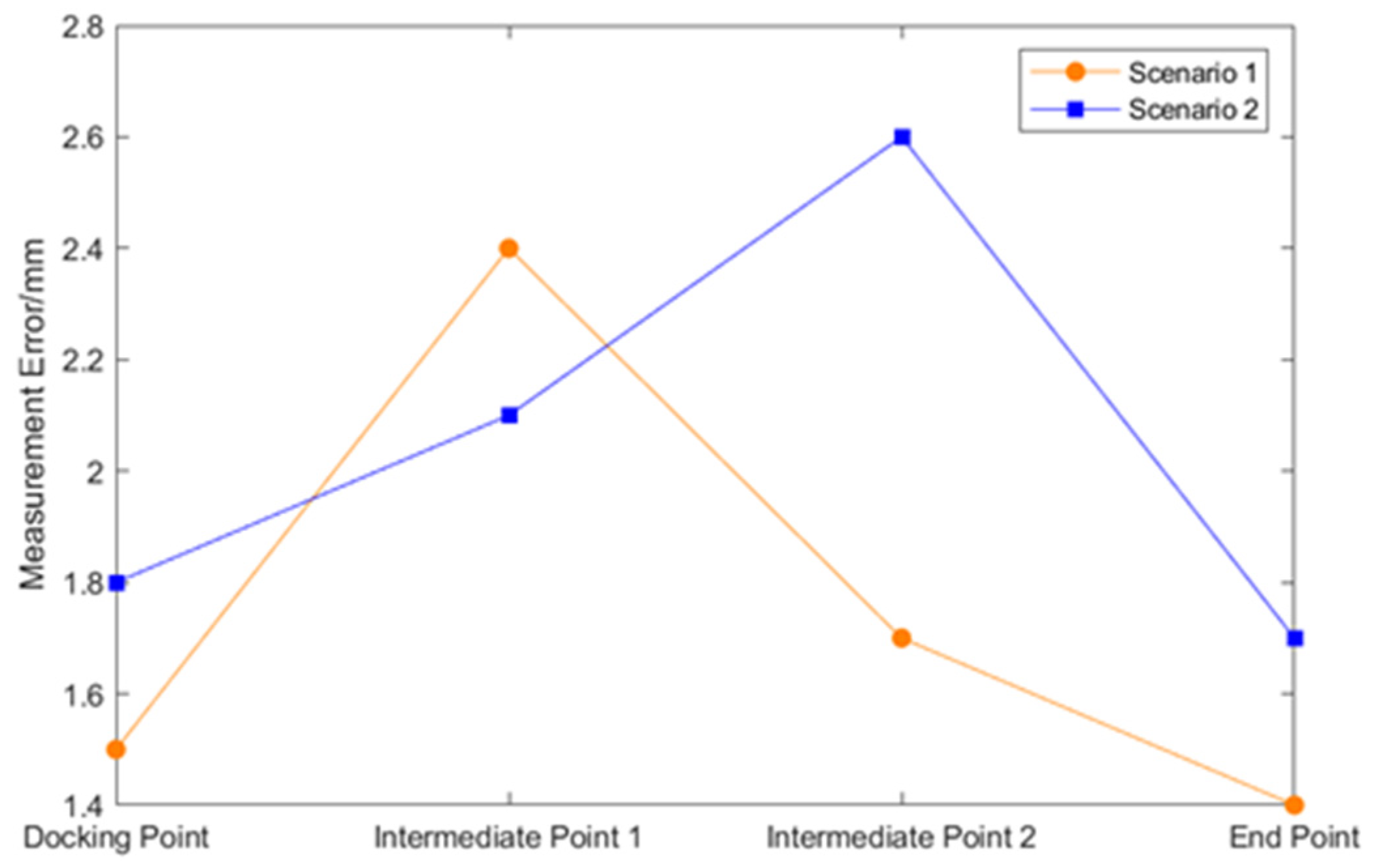
Figure 28.
Motion coordination intermediate point errors.
Figure 28.
Motion coordination intermediate point errors.
Table 1.
D–H parameters of the six-degrees-of-freedom industrial robot.
Table 1.
D–H parameters of the six-degrees-of-freedom industrial robot.
| Link Number | /mm | /rad | /mm | /rad |
|---|
| 1 | 350 | | 684 | |
| 2 | 1200 | 0 | 0 | |
| 3 | 0 | | 0 | |
| 4 | 0 | | 1050 | |
| 5 | 0 | | 0 | |
| 6 | 0 | 0 | 0 | |
Table 2.
Parameters for the discrete simulation of curve trajectory poses.
Table 2.
Parameters for the discrete simulation of curve trajectory poses.
| Name |
Main Pipe Radius |
Branch Pipe Radius |
Rotation Angle |
Eccentricity |
|---|
| Saddle curve | 50 mm | 45 mm | rad | 0 mm |
| Arc curve | 50 mm | 20 mm | 0 rad | 0 mm |
Table 3.
Parameters for central rotational motion.
Table 3.
Parameters for central rotational motion.
| Simulation Parameter Name | Simulation Parameter/(mm, deg) |
|---|
| Initial coordinates of the master robot | |
| Rotation center coordinates of the master robot | |
| Initial coordinates of the slave robot | |
| Time from start point to rotation center | 0~5 s |
| Clockwise 1/2 trajectory time | 5~13 s |
| Counterclockwise 1/2 trajectory time | 13~16 s |
Table 4.
Rigid body translation circular motion parameters.
Table 4.
Rigid body translation circular motion parameters.
| Simulation Parameter Name | Simulation Parameter/(mm, deg) |
|---|
| Initial coordinates of the master robot | |
| Docking point coordinate of the master robot | |
| Initial coordinates of the slave robot | |
| Time from start point to docking point | 0~5 s |
| Time from docking point to 1/4 circle | 5~13 s |
| Time for 3/4 circle to return to docking point | 13~16 s |
Table 5.
Experimental hardware equipment.
Table 5.
Experimental hardware equipment.
| Experimental Equipment | Model | Quantity |
|---|
| Host computer | MECHREVO Code01 | 1 |
| Industrial switch | ICP DAS NS-205 | 1 |
| Controller | NI-cRIO 9030 | 2 |
| Industrial robot | 150 kg Industrial Robot | 2 |
| Actuator | Experimental Equipment | 1 |
| Workpiece | Experimental Equipment | 1 |
Table 6.
Joint angle data calibration for dual-arm robot.
Table 6.
Joint angle data calibration for dual-arm robot.
| Number | /rad | /rad | /rad | /rad | /rad | /rad |
|---|
| 3.3501 | −1.9332 | 0.3150 | −1.1992 | 0.8205 | −1.5709 |
| 2.9103 | −1.7692 | 0.5913 | −2.4699 | 1.0582 | −1.5709 |
| 2.4076 | −1.3606 | −0.3061 | 0.0000 | 1.5709 | −1.5709 |
| 0.0525 | −1.6430 | 0.1389 | −1.3936 | 0.4213 | −0.4161 |
| 0.4697 | −1.5182 | 0.0881 | −1.1845 | 1.1627 | −0.4936 |
| 0.6904 | −1.2629 | 0.1824 | −2.8633 | 1.5296 | −1.1215 |
Table 7.
The measurement values of the intermediate point errors in the experiment.
Table 7.
The measurement values of the intermediate point errors in the experiment.
| | Measurement Error for Scenario 1 | Measurement Error for Scenario 2 |
|---|
| Docking Point | 1.5 mm | 1.8 mm |
| Intermediate Point 1 | 2.4 mm | 2.1 mm |
| Intermediate Point 2 | 1.7 mm | 2.6 mm |
| End Point | 1.4 mm | 1.7 mm |
