Abstract
In this study, to improve the efficiency of the pipetting workstation and reduce the impact of the pipetting device on the stability performance of the workstation, a novel fully automatic pipetting method is proposed. Based on this method, a lightweight, multifunctional, and quantitative twelve-channel pipetting device was designed. This device can achieve simultaneous quantitative liquid absorption for twelve channels and sequential interval liquid discharge for each channel. Initially, the overall functional requirements were determined, and with the aim of a lightweight design, the total weight of the device was controlled to be within 580 g through a reasonable structural design, material selection, and choice of driving source. The device’s overall dimensions are 170 mm × 70 mm × 180 mm (length × width × height), with a micropipetting volume ranging between 1.3 L and 1.4 L. Subsequently, factors affecting liquid suction stability were experimentally analyzed, and appropriate pipetting parameters were selected. The stability performance of this pipetting method during prolonged operation was investigated. Finally, the twelve-channel pipetting device was validated through experiments, demonstrating results that meet the national standards for the stability of a pipetting device. In summary, the device designed in this study exhibits novel design features, low cost, and modularity, thus demonstrating promising potential for applications in high-speed micro-volume pipetting.
1. Introduction
In recent years, the outbreaks of epidemics such as SARS and COVID-19 have heightened the necessity for the rapid screening of numerous suspected infected individuals [1,2,3,4]. Traditional manual testing methods are time-consuming, expensive, and susceptible to sample cross-contamination, underscoring the immediate requirement for efficient testing methods to address this demand [5,6]. Consequently, the adoption of fully automated pipetting workstations has become a prevailing trend in the advancement of the biological and medical domains [7,8].
The pipetting device serves as the central component of a pipetting workstation, chiefly used for precise liquid sample distribution and transfer tasks to guarantee experimental precision and reproducibility [9,10]. The device significantly impacts the workstation’s overall performance and represents a pivotal advancement in augmenting both processing speed and automation level [11]. Common pipetting methods encompass air displacement pipetting, valve switching pipetting, peristaltic pump pipetting, and ultrasonic pipetting. Among these, air displacement pipetting predominates in microliter pipetting technology [12,13]. This mechanism consists of a piston rod and cylinder, meticulously controlling the piston rod’s motion to expel an equal volume of air from the cylinder. Subsequently, it draws the corresponding sample solution into the pipette head, completing the microliter pipetting process [14]. This method offers high precision in microliter pipetting. Valve switching pipetting is accomplished by propelling the sample solution with a high-precision air pump or syringe pump, precisely controlling the liquid discharge valve switch to achieve microliter pipetting [15]. The sample solution passes through a solenoid valve and requires periodic cleaning, rendering it suitable for scenarios demanding continuous liquid transport. Peristaltic pump pipetting [16] entails theh precise control of the peristaltic pump’s rotation for microliter pipetting [17], albeit with lower precision and a heightened risk of sample solution cross-contamination. Ultrasonic pipetting [18] employs a transducer positioned beneath the liquid reservoir to emit precisely focused ultrasonic waves. These waves, leveraging their focused acoustic radiation force, continuously propel tiny liquid droplets upward from the surface of the source container into the target receptacle positioned above the liquid, facilitating the high-precision, non-contact transfer of minute liquid volumes. The minimum volume of liquid transferred can reach 2.5 nL. Nonetheless, this liquid transfer method requires rigorous standards for application, accompanied by increased manufacturing and maintenance costs. Currently, the air displacement pipetting method is predominant [19], yet multi-channel pipetting modules utilizing this technology exhibit large volumes and heavy weights. The majority of multi-channel pipetting modules weigh over 2 kg, with some exceeding 10 kg. The high-speed operation of a pipetting workstation’s robotic arm induces significant inertial forces in the pipetting module, greatly compromising the workstation’s stability and severely constraining its operating speed and pipetting capacity.
Building upon the aforementioned issues, this paper introduces a liquid suction method that utilizes the deformation of elastic rubber tubes. This study designed a novel lightweight, multifunctional, and reusable multi-channel microliter pipetting device. The device offers a range of functionalities: it mixes sample solutions before liquid suction, simultaneously suctions microliter volumes across twelve channels, sequentially discharges liquid at equal intervals for twelve channels, automatically installs and removes the pipette head, and allows the manual adjustment of channel spacing across two levels. During liquid suction, an electromagnet acts as the driving force, enabling simultaneous quantitative microliquid suction across all 12 pipetting channels. Liquid discharge is achieved using a stepper motor as the sole driving source. Due to an ingenious structural design, the motor can independently regulate all 12 pipetting channels, ensuring sequential liquid discharge at uniform intervals. Additionally, the multifunctional reusable liquid discharge component allows for sample solution mixing before liquid suction. The primary benefits of this design are its lightweight construction and multifunctionality, with the entire pipetting device weighing a mere 580 g, thus reducing its impact on the robotic arm. This approach mitigates the workstation’s stability issues, enhances pipetting speed, and significantly contributes to overall workstation performance improvement.
This study explored the factors affecting the device’s liquid handling stability and derived suitable parameters based on experimental data analysis. Furthermore, the liquid handling stability of the device during extended operation was examined. Experimental results indicate that after conducting 500 consecutive liquid transfers for over four hours, the liquid transfer repeatability was 4.06%, meeting practical usage standards. Lastly, the consistency of the liquid handling across all 12 channels of the device was assessed. Experimental results revealed that the average liquid transfer volume per channel ranged from 1.32 to 1.41 L, with liquid transfer repeatability between 3.63% and 4.61%. The average liquid transfer volume across all 12 channels was 1.38 L, aligning with the design specifications of the liquid handling device. This study aimed to design a lightweight, multifunctional multi-channel liquid handling device to meet the market demand for high-precision microliquid handling across multiple channels.
2. Materials and Methods
2.1. Pipetting Method Based on Deformation of Elastic Rubber Tubing
Existing pipetting methods have been improved, and this study introduces a novel approach considered a “pipetting method based on elastic rubber tubing deformation”. The fundamental principle of this approach entails modifying the volume within the pipetting channel by deforming the elastic rubber tube, consequently altering the pressure and generating a pressure differential. This pressure differential enables the sample solution to be drawn into the pipette head, accomplishing microliter liquid suction. The liquid suction structure comprises a base plate, a liquid suction plate, a liquid suction extrusion plate, two sliding rods, four bolts, two electromagnets, two springs, and the pipetting channel. The pipetting channel comprises the elastic rubber tube, pipette head mounting tube, and pipette head, as depicted in Figure 1.
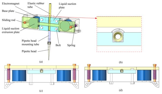
Figure 1.
(a) Schematic of a single-channel pipette method based on the deformation of elastic rubber tubes. (b) Local sectional view illustrating the positioning of the elastic rubber tube and the liquid suction extrusion plate. (c) Schematic illustrating the position of the liquid suction extrusion plate when the electromagnet is not energized. (d) Schematic illustrating the position of the liquid suction extrusion plate when the electromagnet is energized.
The liquid suction plate is centrally secured to the base plate with four bolts, flanked by two electromagnets on each side, and two sliding rods fixed on either side of the electromagnets. The liquid suction extrusion plate is installed on these rods, which have springs mounted on them. An elastic rubber tube is fixed within the groove of the liquid suction plate, connected at its lower end to the pipette head mounting tube, and equipped with a disposable pipette head. This design not only improves the pipetting efficiency of the workstation but also introduces a novel technical solution for handling microliter samples.
During liquid suction, when the disposable pipette head is not inserted below the liquid surface, both electromagnets are energized simultaneously. The liquid suction plate slides on the sliding rods under the magnetic force of the electromagnets and adheres to their end faces. At this point, both the springs on the sliding rods and the elastic rubber tube in the pipette channel are compressed simultaneously. Upon the insertion of the disposable pipette head below the liquid surface, a sealed space is formed inside the pipette channel with the sample liquid. Subsequently, both electromagnets are powered off simultaneously, and the magnetic force disappears. During this process, the springs drive the liquid suction plate back to its initial position, and the elastic rubber tube regains its initial shape due to its own elasticity. At this moment, the volume inside the sealed pipette channel increases, leading to a decrease in internal pressure. The internal pressure difference and the external ambient pressure form a pressure difference. The liquid is pushed into the disposable pipette head under the influence of this pressure difference, completing precise quantitative liquid transfer.
The experimental results in Figure 2 show that the pressure inside the pipette channel varies with time during liquid aspiration, as measured by a pressure sensor (JY-PS040, WitMotion Shenzhen Co., Ltd., Shenzhen, China). Inserting the pipette head below the liquid surface creates a sealed space between the internal pipette channel and the sample liquid. Prior to time point a, the internal pressure inside the pipette channel reaches equilibrium. At time point a, both electromagnets suddenly power off, causing the elastic rubber tube to regain its shape. This sudden increase in the internal volume of the pipette channel causes a sharp drop in internal pressure, reaching its minimum value. Due to the pressure differential, the liquid enters the pipette head, resulting in a gradual increase in the internal pressure of the pipette channel. At time point b, the internal pressure inside the pipette channel, the aspirated liquid, and the external pressure reach equilibrium, thus completing the liquid aspiration process. After time point b, the internal pressure inside the pipette channel remains constant.
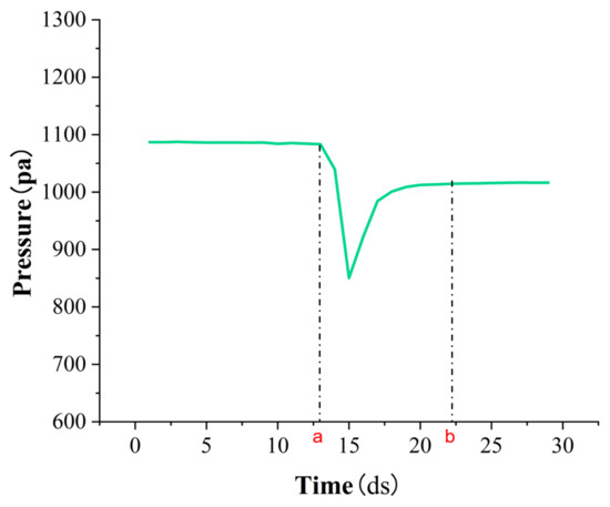
Figure 2.
Pressure changes inside the pipette channel.
2.2. Overall Design of Pipette Device
This study proposes a deformation pipetting method using an elastic rubber tube to enhance the existing technique. Additionally, a twelve-channel multifunctional, lightweight, quantitative microliter pipetting device was designed. The device, depicted in Figure 3 comprises a shell and components, including liquid suction, liquid discharge, variable spacing, and the automatic removal of the pipette head. The liquid suction component is driven by two equally sized miniature electromagnets, which are small and lightweight and have a fast response speed. The liquid discharge component is powered by a stepper motor, rotating the rod on the shaft to enable the mixing of the sample solution and sequential discharge from all twelve channels at equal intervals. Through rational designs of the pipetting components, the total mass of this pipetting device was controlled to remain within 580 g, reducing the weight of the pipetting device and minimizing its impact on the stability performance of the pipetting workstation.
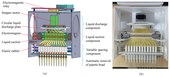
Figure 3.
(a) The liquid suction component can simultaneously perform quantitative liquid suction for all twelve channels. The liquid discharge component can sequentially discharge liquid from all twelve channels at equal intervals and mix the sample solution before suction. The variable spacing component allows the manual adjustment of the spacing between the twelve channels. The component for the automatic removal of the pipette head can simultaneously remove disposable pipette heads from all twelve channels. (b) The physical pipette device.
2.3. Designs of Key Components
2.3.1. Liquid Suction Component
The primary function of the liquid suction component is to quantitatively extract liquid from 12 pipetting channels simultaneously. This comprises a base plate, a liquid suction plate, two electromagnets, two sliding rods, a liquid suction extrusion plate, four bolts, and two springs, as illustrated in Figure 4. The liquid suction plate features installation slots for the 12 pipetting channels, with a center-to-center spacing of 6 mm between adjacent slots. The 12 pipetting channels are situated within the grooves of the liquid suction plate. The liquid suction plate is centrally secured to the base plate using four bolts of identical specifications. Electromagnets of identical specifications are positioned on either side of the liquid suction plate, each with two fixed sliding rods. Springs are affixed to the two sliding rods. The liquid suction extrusion plate is mounted on these two sliding rods and can slide when subjected to external force. The end faces of the two electromagnets align, flushed with the front end face of the liquid suction plate.
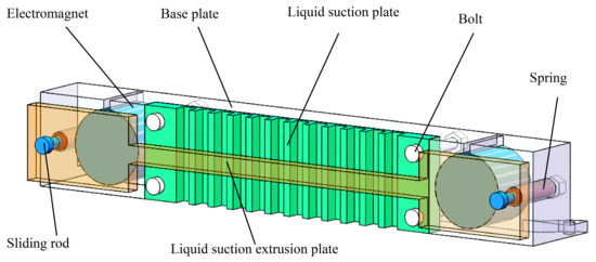
Figure 4.
Liquid suction component structure diagram.
At the initial stage of the liquid suction process, both electromagnets are simultaneously activated. This action causes the liquid suction extrusion plate to slide along the sliding rod and adhere to the end face of the electromagnet due to magnetic force. Simultaneously, it compresses the elastic rubber tubes in each pipetting channel and the springs on the sliding rod. Upon inserting the disposable pipette head beneath the liquid surface of the sample solution, a sealed space forms between the interior of the pipetting channel and the sample solution. Subsequently, both electromagnets are simultaneously deactivated, causing the magnetic force to dissipate. As a result, the liquid suction extrusion plate slides back to its initial position under the action of the spring, allowing the volume of the elastic rubber tubes in each pipetting channel to recover. The change in volume of the pipetting channel induces a pressure change inside the channel, creating a pressure difference. Consequently, the sample solution is drawn into the disposable pipette head, completing the simultaneous quantitative liquid suction of all 12 pipetting channels.
2.3.2. Liquid Discharge Component
The primary function of the liquid discharge component is to mix the sample solution before suction and then, after suction is complete, sequentially discharge the sample solution from the 12 pipetting channels at regular intervals. This component comprises a circular liquid discharge plate, a stepper motor, a rotating rod, a connecting plate, and 2 bolts, as depicted in Figure 5. The structural characteristics of the circular liquid discharge plate are as follows. The plate is divided into three sections, with a total height of 18 mm and an outer diameter of 50 mm. The middle section has a height of 8 mm, and both ends have equal heights of 5 mm. The inner diameter of the middle section is 43 mm, and both ends have equal inner diameters of 30 mm. Each pipetting channel mounting hole has a diameter of 4 mm, and they are arranged in a circle with a diameter of 20 mm from the axis of the circular liquid discharge plate, and the angle between the center of the adjacent mounting hole and the center of the cylinder is 30°, separated by 10.35 mm. The stepper motor is mounted on the end face of the circular liquid discharge plate, with its shaft aligned with the plate’s axis. The rotating rod length is 19 mm, and the tip width is 4.1 mm. The rod is mounted on the motor shaft of the stepper motor and rotates within the middle section of the circular liquid discharge plate.
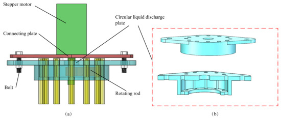
Figure 5.
(a) Liquid discharge component structure diagram; (b) cross-sectional view of the circular liquid discharge plate.
During the liquid discharge process, the rotation of the stepper motor controls the sequential squeezing of the elastic rubber tubes in the pipetting channels by the rotor. During squeezing, the volume inside the pipetting channels decreases, expelling the gas in the tube and pushing out the sample solution from the disposable pipette head, thereby achieving liquid discharge. With each 30° rotation of the stepper motor, one elastic rubber tube in the pipetting channels is squeezed, completing the liquid discharge for that channel. Precisely controlling the angle and rotation time of the stepper motor according to the requirements enables liquid discharge at equal intervals of time for all 12 pipetting channels. The greater deformation of the elastic rubber tube during liquid discharge, compared to liquid suction, allows for the smooth expulsion of the sample solution from the disposable pipette head, thereby addressing the inability to dispense small amounts of liquid within the pipette head due to liquid surface tension effects. Moreover, before liquid suction, when the 12-channel disposable pipette head is inserted beneath the sample solution, the stepper motor rapidly rotates one full circle, facilitating the quick aspiration of a larger amount of sample solution by the 12 pipetting channels. As each channel’s disposable pipette head exits the sample solution surface, the stepper motor rapidly rotates one full circle to expel the sample solution from the 12 pipetting channels, thus achieving the mixing of the sample solution before liquid suction.
2.3.3. Automatic Pipette Head Removal Component
The primary function of the pipette head removal component is to remove the disposable pipette head mounted on the pipette head mounting tube after pipetting is completed. It comprises two springs, an upper removal head plate, a lower removal head plate, and an electromagnetic relay, as depicted in Figure 6. In using the power of the electromagnetic relay, the upper removal head plate is driven downward to simultaneously remove the pipette head from all 12 channels.
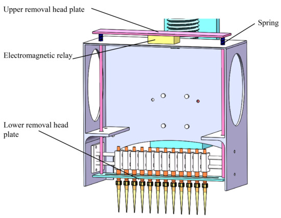
Figure 6.
Automatic pipette head removal component structure diagram.
In this process, the electromagnetic relay is first activated, causing the upper removal head plate to move downward, followed by the lower removal head plate, resulting in the simultaneous detachment of the disposable pipette heads from all 12 pipetting channels. At this point, the two springs are compressed. Afterward, the electromagnetic relay is deactivated, allowing the compressed springs to begin to recover, and the lower and upper removal head plates return to their initial positions, completing the removal of the pipette heads from all 12 pipetting channels.
2.4. Material Selection and Production of Key Components
For each component, lightweight materials were selected to meet usage requirements, aiming to minimize the overall module weight for a lightweight design. The bottom plate and pipette head mounting tube in the liquid suction component, as well as the circular liquid discharge plate and rotating rod in the liquid discharge component, were all fabricated using 3D printing technology (Cangnan Weihe Trading Co., Ltd., Wenzhou, China), utilizing high-precision resin as the printing material. This material offers a high printing precision, a light weight, a dimensional accuracy of up to ±50 m, and low processing costs. For the liquid suction component, a 5 mm Polymeric Methyl Methacrylate board (Dongguan Miaozi Trade Co., Ltd., Dongguan, China) was chosen for the liquid suction plate material, valued for its good wear resistance, stability, and processing performance. Additionally, 420 martensitic stainless steel (Taizhou Shenzhao Metal Material Co., Ltd., Taizhou, China) was chosen for the liquid suction extrusion plate material, providing high hardness, tensile strength, and magnetic properties. Two electromagnets (Wenzhou Tuochi Technology Co., Ltd., Wenzhou, China) with an outer diameter of 20 mm and a height of 15 mm were chosen for the electromagnetic iron parts, known for their strong magnetic force, light weight, and compact size. The selected elastic rubber tube (Shanghai Tuohong Decoration Materials Co., Ltd., Shanghai, China) has an outer diameter of 4 mm and an inner diameter of 2 mm. The material of the elastic rubber tube is natural latex, with an elastic modulus of greater than or equal to 1.5 MPa. It exhibits excellent elasticity at room temperature, capable of promptly restoring its original shape after experiencing force. Additionally, it has high resistance to wear and aging, enabling it to maintain stable resilience over extended periods. The grooves in the bottom plate were machined using a vertical Computer Numerical Control milling machine (X5 combo, Sayre Machine Tools Co., Ltd., Ningbo, China) with a machining precision of ±20 m. The model of the stepper motor is 35H3340A4 (SUMTOR (Wuxi) Electric Co., Ltd., Wuxi, China). The electromagnetic relay selected is GPM0946U (Beijing Enliji Technology Co., Ltd., Beijing, China).
2.5. Control Scheme
The control scheme of the pipetting module involves transmitting commands from an upper computer to a lower computer, which subsequently sends corresponding control signals to various driving sources. The lower computer utilizes the STM32F103 series microcontroller manufactured by STMicroelectronics to primarily control the electromagnet in the liquid suction component for simultaneous quantitative liquid suction in twelve channels, the stepper motor in the liquid discharge component for interval-based liquid dispensing, and the electromagnetic relay in the pipette head removal component for the simultaneous removal of pipette heads in twelve channels. Control of the stepper motor is primarily achieved through the microcontroller’s internal timer, which generates Pulse-Width Modulation (PWM) signals [20], enabling the precise control of the stepper motor’s rotation by configuring suitable PWM generation parameters according to the desired rotation angle and speed. When controlling the electromagnet and electromagnetic relay, relay components are employed. The microcontroller transmits corresponding commands to the relay, which function as circuit control switches, accurately controlling the on–off state to regulate the electromagnet and electromagnetic relay. This control scheme effectively enables the precise operation and control of the pipetting module. A control flowchart of the pipetting module is illustrated in Figure 7 below.
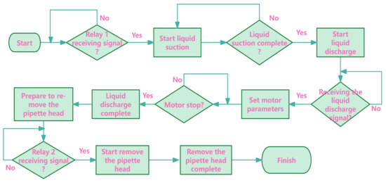
Figure 7.
Control flow chart of pipette module.
3. Results and Analysis
3.1. Analysis of Influencing Factors of Pipette Stability
The stability of the pipetting method directly impacts the device’s performance. Various factors influence stability, including environmental conditions (such as temperature, humidity, and evaporation rate), as well as operational parameters like rubber tube length, liquid immersion depth, and residence time after liquid suction. This study’s experiment primarily employed the method of controlling variables to investigate the impact of these factors on pipetting stability, aiming to optimize parameters and enhance the stability performance. Quantitative liquid suction was conducted using pure water at a room temperature of 25 °C. The weight of each pipette operation was measured using a high-precision electronic balance (Mettler ME204T, Shanghai Jianrong Industrial Co., Ltd., Shanghai, China) to determine the volume of the liquid suctioned. Thirty experiments were conducted for each set of parameters to determine the average pipetting volume and repeatability. An analysis of the experimental data enabled the selection of optimal pipetting parameters to enhance thhe stability performance, ensuring the accuracy and reproducibility of the experimental results. The formula for repeatability is as follows:
where is the standard deviation, is the average value of 30 actual measurements, is the square of the difference between a single measurement and the measured mean value, n is the number of measurements, and S is the repeatability of the measurements. The larger the calculated value of the measurements’ repeatability, the more unstable the suction.
3.1.1. Liquid Immersion Depth
The depth of liquid suction, whether excessively deep or too shallow, can significantly influence the outcomes of the process. Excessive depth during aspiration may cause the instrument to contact the container’s bottom, resulting in considerable inaccuracies; conversely, insufficient depth may lead to incomplete suction or air bubble formation. For the experiment, aspiration depths ranging from 0.5 mm to 2 mm were chosen to assess their effects on the stability of liquid aspiration. Simultaneously, the residence time after suction was set to 1.2 s using a 60 mm elastic rubber tube. Thirty experiments were performed per parameter set to determine both the mean pipetting volume and its repeatability. Figure 8 displays pertinent experimental findings, while Table 1 provides a comprehensive stability analysis based on these results. This experimental configuration aimed to elucidate the precise influence of the liquid immersion depth on the stability of the liquid aspiration, ultimately enhancing pipetting efficiency.
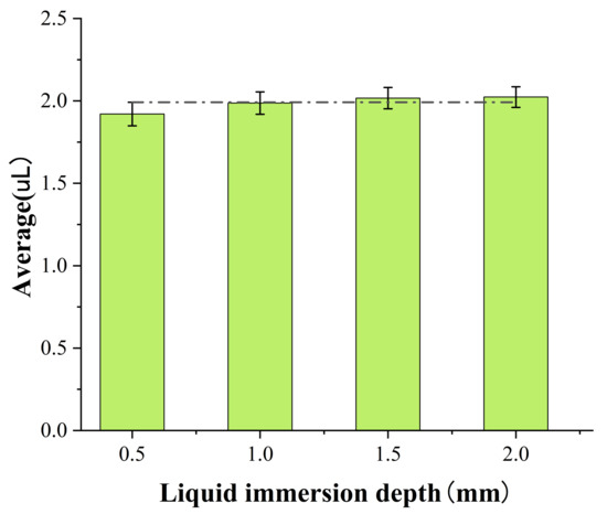
Figure 8.
Influence of immersion depth on liquid suction stability.

Table 1.
Stability analysis of the experimental results on the liquid immersion depth.
Based on the data from Figure 8 and Table 1, as the liquid immersion depth increases, the repeatability of liquid absorption gradually decreases. However, when the liquid immersion depth reaches 1.5 mm, the repeatability of liquid suction begins to stabilize. Therefore, selecting an appropriate liquid immersion depth is crucial when performing liquid suction operations. For liquid volumes of 2 L and below, choosing 1.5 mm as the liquid immersion depth is more suitable.
3.1.2. Residence Time after Liquid Suction
The residence time after liquid suction directly influences the accuracy and stability of pipetting. Insufficient residence time may prevent the pressure inside the chamber from stabilizing, resulting in incomplete liquid suction and significant errors. Conversely, an excessively long residence time prolongs the liquid aspiration process, thereby impacting the workstation’s overall efficiency. Therefore, this study examined various retention times—0.4 s, 0.8 s, 1.2 s, and 1.6 s—with a liquid immersion depth of 1.5 mm and using a 60 mm long elastic rubber tube. The experimental findings are illustrated in Figure 9, while Table 2 provides a stability analysis based on these results. The experimental design aimed to determine the optimal residence time for ensuring liquid stability while minimizing the impact on work efficiency.
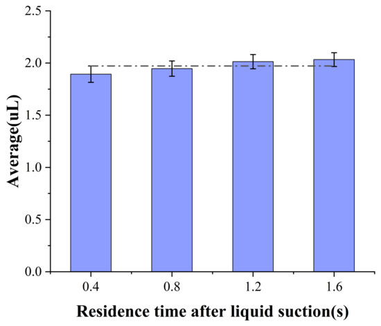
Figure 9.
Influence of residence time after suction on liquid suction stability.

Table 2.
Stability analysis of the experimental results on the residence time after liquid suction.
According to the data presented in Figure 9 and Table 2, there is a decrease in the repeatability of liquid aspiration as the residence time after aspiration increases. The immediate power cut-off of the electromagnet during liquid suction causes the rapid recovery of the elastic rubber tube, leading to substantial fluctuations in the internal air pressure of the chamber. To maintain the stability of liquid aspiration, a minimum residence time of 1 s after liquid suction is necessary.
3.1.3. Rubber Tube Length
Fluctuations in the air volume within the pipetting channel directly influence the pressure within the chamber, serving as the driving force behind the liquid suction process. Variations in the lengths of the elastic rubber tube can induce discrepancies in pressure fluctuations within the chamber during liquid aspiration, thereby impacting the duration needed to achieve a stable pressure state. For this experiment, elastic rubber tubes measuring 40 mm, 60 mm, 80 mm, and 100 mm in length were chosen to investigate their respective effects on the stability of liquid suction. The experiment set the residence time after liquid suction time to 1.2 s and the liquid immersion depth to 1.5 mm. The experimental results are shown in Figure 10, and Table 3 presents the stability analysis of the experimental results. Through this experimental setup, the aim was to investigate the precise influence of the elastic rubber tube length on the stability of liquid aspiration, with the objective of optimizing the pipetting performance.
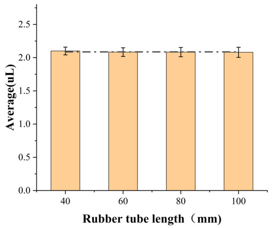
Figure 10.
Influence of pipe length on liquid suction stability.

Table 3.
Stability analysis of the experimental results on the pipe length.
According to the data from Figure 10 and Table 3, there is an observed increase in the repeatability of liquid suction with the length of the elastic rubber tube. With an increase in the length of the elastic rubber tube, both the height of the air column and the stiffness of the air spring decrease. Consequently, the fluctuation of internal air pressure during liquid suction becomes more pronounced. To ensure the stability of liquid aspiration, it is essential to select the appropriate length of the elastic rubber tube based on the specific design requirements.
3.2. Stability Performance of Pipetting Method Based on Deformation of Elastic Rubber Tubing during Prolonged Pipetting
To assess the long-term stability of this pipetting method, we measured variations in the volume of liquid suction through a single channel over prolonged periods of pipetting. Under the conditions of a liquid immersion depth of 1.5 mm, a residence time after liquid suction of 1.2 s, and a driving voltage in the electromagnets of 24 V, we recorded the volume of the liquid aspiration during each pipetting event. The experimental results are depicted in Figure 11.
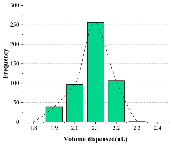
Figure 11.
The impact of the number of pipetting cycles on stability.
As depicted in Figure 11, the average volume of liquid aspiration was 2.09 L, with fluctuations ranging from 1.9 L to 2.3 L. The repeatability of the pipetting process is 4.06%, satisfying the requirements specified by national standards for pipettes. This pipetting method exhibits excellent long-term stability and high efficiency, fulfilling daily operational requirements. Following the continuous execution of 500 experiments over nearly four and a half hours, the electromagnets experienced significant heating, leading to a decrease in magnetic force and consequently concluding the experiment.
The heating of the electromagnet will impact the device’s operation time. Thus, in future improvement endeavors, we will aim to enhance the structure and choose better-suited electromagnets to lessen operational heat generation. This will enhance the pipetting time stability and efficiency.
3.3. Pipette Stability Verification Experiment
The pipetting device requires high stability. A highly stable pipetting device is essential to meet precise experimental requirements and enhance the reliability and accuracy of results. This pipetting device can quantitatively suction and sequentially dispense liquids through 12 channels, with the capability for fully automatic pipette head removal. This experiment aimed to measure and analyze the stability of liquid aspiration for each channel of the pipetting device. The experiment set the residence time after liquid suction time to 1.2 s and the liquid immersion depth to 1.5 mm. Pure water served as the experimental material at a room temperature of 25 °C. The weight of each pipetting operation was measured using a high-precision electronic balance (Mettler ME204T, Shanghai Jianrong Industrial Co., Ltd., Shanghai, China) to calculate the volume of liquid suction. Each channel underwent 20 experiments, and the statistics of liquid suction for all 12 channels are depicted in Figure 12.
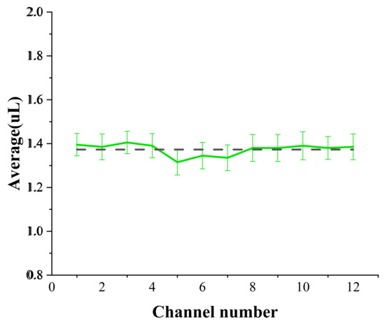
Figure 12.
The statistics of liquid suction for the 12 channels.The solid line represents the actual pipetting volume of each channel, while the dashed line represents the average pipetting volume of the 12 channels.
The repeatability of liquid suction for the 12 channels was calculated and analyzed using formulas (1) and (2) from Analysis of influencing factors of pipette stability, with results presented in Table 4.

Table 4.
The repeatability of liquid suction for the 12 channels.
Figure 12 and Table 4 indicate that the average volume of liquid suction per channel ranged from 1.32 to 1.41 L, with repeatability rates ranging from 3.63% and 4.64%. The average volume of liquid suction for all 12 channels was 1.38 L, with an average consistency repeatability rate of 1.97%. According to the experimental findings, the volume of liquid suction in the middle channel is slightly lower than that in the side channels. This phenomenon can be attributed to the placement of the liquid suction driving source on both sides of the pipetting channel. The activation of the electromagnets causes slight deformation in the middle section of the liquid suction extrusion plate, leading to a minor decrease in the compression of the elastic rubber tubing in the middle channel. Nevertheless, the impact of this effect is minimal, and the consistency of multi-channel liquid transfer continues to meet operational requirements.
The pipetting device exhibits excellent stability in liquid transfer, satisfying the standard requirements stipulated in the Chinese National Metrological Testing Regulations (JJG 646-2006, Verification Regulation of Locomotive Pipette, China), meeting design specifications, and fulfilling practical usage demands.
However, the pipetting device is currently limited to micro-volume quantitative pipetting. Once manufactured, its pipetting volume cannot be adjusted, restricting its use mainly to large-scale sample solution detection. Future designs should focus on structural enhancements to enable pipetting across various volume ranges, thus broadening its scope of application and increasing its utility value.
3.4. Comparison between the Designed Scheme and Existing Schemes
To illustrate the characteristics of our design approach, we compared the technical solution of this study with some existing typical pipetting modules in terms of key parameters, mainly focusing on the pipetting method, driving source, channel quantity, mass, minimal pipetting capacity, and pipetting stability, as shown in Table 5.

Table 5.
Comparison of different liquid-handling devices.
As illustrated in Table 5, the approach designed in this study adopts the elastic rubber tube deformation pipetting method, in contrast to the air displacement pipetting method. In utilizing elastic rubber tube deformation for pipetting, the structural design demonstrates ingenuity and innovation, while the manufacturing process remains simple and cost-effective.
In terms of the driving source selection, in the air displacement pipetting method, each pipetting channel necessitates a corresponding driving source to achieve independent control across multiple channels. Compared to alternative solutions, this design employs either a single driving source or the reuse of driving sources to achieve independent control across multiple channels, thereby reducing the number of driving sources and substantially decreasing the total weight of the device, which is a mere 580 g. As for the number of channels, this design boasts a higher number of channels that can be individually controlled, thus augmenting operational efficiency. Despite its classification as a quantitative pipetting module, this design excels in achieving high-precision micro-volume pipetting. The pipetting stability of this design is at the same level as or even superior to the three mentioned design schemes. The primary features of this design device include its lightweight construction, multifunctionality, and high precision in quantitative micro-volume pipetting.
4. Conclusions
This study introduced enhancements to existing pipetting methods by proposing a novel approach based on the deformation of an elastic rubber tube. Liquid suction is achieved using only an electromagnet as the driving source, deforming the elastic rubber tube. In building upon this pipetting method, a novel lightweight multi-channel microliter pipetting device was developed, featuring diverse functions tailored to various usage scenarios. With a total mass limited to 580 g, the device’s overall dimensions are 170 mm × 70 mm × 180 mm, with a micropipetting volume ranging between 1.3 L and 1.4 L. This device reduces the weight of multi-channel pipetting devices, thus minimizing the impact on the stability of the pipetting workstation
Through experimental analysis, we identified key factors influencing the pipetting stability and selected appropriate parameters to ensure accurate and repeatable results. The pipetting stability performance of the device was evaluated during prolonged operation, demonstrating its ability to maintain stable pipetting for more than four hours. Upon the heating and subsequent cessation of pipetting by the electromagnet, the device resumes operation once the temperature reverts to room temperature. Moreover, the feasibility of the pipetting device was confirmed, meeting the design specifications. This device’s development significantly improves the efficiency of pipetting workstations and provides valuable insights for future lightweight designs.
Author Contributions
Conceptualization, X.Z.; Methodology, X.Z.; Investigation, X.Z. and Z.Y.; Data Curation, X.Z.; Visualization, X.Z.; Writing—Original Draft, X.Z.; Project Administration, L.L.; Writing—Review and Editing, C.Z. and H.Y.; Supervision, L.L. and H.Y.; Resources, X.Z.; Funding Acquisition, H.Y. All authors have read and agreed to the published version of the manuscript.
Funding
This study was supported by the National Natural Science Foundation of China (Grant No. 62304057) and Guangxi Bagui Scholars Project (No. 2019A02).
Institutional Review Board Statement
Not applicable.
Informed Consent Statement
Not applicable.
Data Availability Statement
Data are contained within the article.
Conflicts of Interest
The authors declare no conflicts of interest.
References
- Singh, J.; Malik, D.; Raina, A. Computational investigation for identification of potential phytochemicals and antiviral drugs as potential inhibitors for RNA-dependent RNA polymerase of COVID-19. J. Biomol. Struct. Dyn. 2022, 40, 3492–3507. [Google Scholar] [CrossRef] [PubMed]
- Mahrosh, H.; Mustafa, G. An in silico approach to target RNA-dependent RNA polymerase of COVID-19 with naturally occurring phytochemicals. Environ. Dev. Sustain. 2021, 23, 16674–16687. [Google Scholar] [CrossRef] [PubMed]
- Nkengasong, J. China’s response to a novel coronavirus stands in stark contrast to the 2002 SARS outbreak response. Nat. Med. 2020, 26, 310–311. [Google Scholar] [CrossRef] [PubMed]
- Negi, M.; Chawla, P.; Faruk, D.; Chawla, V. Role of heterocyclic compounds in SARS and SARS CoV-2 pandemic. Bioorg. Chem. 2020, 104, 104315. [Google Scholar] [CrossRef] [PubMed]
- Councill, E.; Axtell, N.; Thy, T.; Liang, Y.; Aposhian, A.; Webber, K.; Zhu, Y.; Cong, Y.; Carson, R.; Kelly, R. Adapting a Low-Cost and Open-Source Commercial Pipetting Robot for Nanoliter Liquid Handling tubes. SLAS Technol. Transl. Life Sci. Innov. 2020, 26, 311–319. [Google Scholar]
- Fan, J.; Men, Y.; Tseng, K.; Ding, Y.; Ding, Y.; Villarreal, F.; Tan, C.; Li, B.; Pan, T. Dotette: Programmable, high-precision, plug-and-play droplet pipetting. Biomicrofluidics 2018, 12, 034107. [Google Scholar] [CrossRef] [PubMed]
- Grau Escribano, J.; Benedé, J.; Chisvert, A.; Salvador, A. A high-throughput magnetic-based pipette tip microextraction as an alternative to conventional pipette tip strategies: Determination of testosterone in human saliva as a proof-of-concept. Anal. Chim. Acta 2022, 1221, 340117. [Google Scholar] [CrossRef] [PubMed]
- Dayon, L.; Macron, C.; Lahrichi, S.; Galindo, A.N.; Affolter, M. Proteomics of Human Milk: Definition of a Discovery Workflow for Clinical Research Studies. J. Proteome Res. 2021, 20, 2283–2290. [Google Scholar] [CrossRef] [PubMed]
- Sungkawa, H.; Endiani, R. Precision and Accuracy Analysis of Forward Method Pipetting and Reverse Method Pipetting by Technology of Medical Laboratory Students Pontianak. J. Lab. Khatulistiwa 2019, 2, 41–43. [Google Scholar] [CrossRef]
- Kerswell, R. Micropipette tips—The unsung heroes of mass spectrometry. Rapid Commun. Mass Spectrom. RCM 2008, 22, 2349–2354. [Google Scholar]
- Wang, J.; Deng, K.; Zhou, C.; Fang, Z.; Meyer, C.; Deshpande, K.; Li, Z.; Mi, X.; Luo, Q.; Hammock, B.; et al. Microfluidic cap-to-dispense (μCD): A universal microfluidic–robotic interface for automated pipette-free high-precision liquid handling. Lab Chip 2019, 19, 3405–3415. [Google Scholar] [CrossRef] [PubMed]
- Feldmann, R.; Lochner, K. Influences on volume in piston-operated air-displacement pipettes. Accredit. Qual. Assur. 2016, 21, 69–82. [Google Scholar] [CrossRef]
- Zhu, L.; Li, H.; Guo, Y. Novel Method for ELISA Traces Pipetting System by Air Displacement Pipetting. Appl. Mech. Mater. 2011, 103, 252–256. [Google Scholar] [CrossRef]
- Mao, Y.; Pan, Y.; Li, X.; Li, B.; Chu, J.; Pan, T. High-Precision Digital Droplet Pipetting Enabled by Plug-and-Play Microfluidic Pipetting Chip. Lab Chip 2018, 18, 2720–2729. [Google Scholar] [CrossRef] [PubMed]
- Yang, X.; Wang, X.; Li, B.; Chu, J. A high-precision automated liquid pipetting device with an interchangeable tip. Rev. Sci. Instrum. 2023, 94, 094102. [Google Scholar] [CrossRef] [PubMed]
- Cataño, J.; Farthing, S.; Mascarenhas, Z.; Lake, N.; Yarlagadda, P.; Li, Z.; Toh, Y.-C. A User-Centric 3D-Printed Modular Peristaltic Pump for Microfluidic Perfusion Applications. Micromachines 2023, 14, 930. [Google Scholar] [CrossRef] [PubMed]
- Behrens, M.; Fuller, H.; Swist, E.; Wu, J.; Islam, M.M.; Long, Z.; Ruder, W.; Steward, R. Open-source, 3D-printed Peristaltic Pumps for Small Volume Point-of-Care Liquid Handling. Sci. Rep. 2020, 10, 1543. [Google Scholar] [CrossRef] [PubMed]
- Ning, Y.; Zhang, M.; Zhang, H.; Duan, X.; Yuan, Y.; Liu, B.; Pang, W. Mechanism and stability investigation of a nozzle-free droplet-on-demand acoustic ejector. Analyst 2021, 146, 5650–5657. [Google Scholar] [CrossRef] [PubMed]
- Yao, Y.; Ma, J.; Liu, H. Application of Pressure Liquid Level Detection Technology in the Automatic Micropipette Module. In Proceedings of the 2nd International Conference on Robotics and Automation Sciences (ICRAS2018), Wuhan, China, 23–25 June 2018; pp. 179–183. [Google Scholar]
- Hara, T.; Taniguchi, S.; Ajima, T.; Sawahata, M.; Hori, M.; Tsukagoshi, T.; Hoshino, K. Synchronous PWM Control With Carrier Wave Phase Shifts for Permanent Magnet Synchronous Motor. IEEE Trans. Ind. Appl. 2022, 58, 5650–5658. [Google Scholar] [CrossRef]
- Barthels, F.; Barthels, U.; Schwickert, M.; Schirmeister, T. FINDUS: An open-source 3D printable liquid-handling workstation for laboratory automation in life sciences. SLAS Technol. Transl. Life Sci. Innov. 2020, 25, 190–199. [Google Scholar] [CrossRef] [PubMed]
Disclaimer/Publisher’s Note: The statements, opinions and data contained in all publications are solely those of the individual author(s) and contributor(s) and not of MDPI and/or the editor(s). MDPI and/or the editor(s) disclaim responsibility for any injury to people or property resulting from any ideas, methods, instructions or products referred to in the content. |
© 2024 by the authors. Licensee MDPI, Basel, Switzerland. This article is an open access article distributed under the terms and conditions of the Creative Commons Attribution (CC BY) license (https://creativecommons.org/licenses/by/4.0/).