Article

Natural Characteristics of a Marine Two-Stage Tandem Hybrid Planetary System

1
School of Mechanical Engineering & Automation, Beihang University, Beijing 100083, China
2
School of Mechanics Engineering, Harbin Institute of Technology, Harbin 150001, China
3
School of Mechanics and Mathematics, Belarusian State University, 220030 Minsk, Belarus
*
Author to whom correspondence should be addressed.
Machines 2024, 12(5), 338; https://doi.org/10.3390/machines12050338
Submission received: 13 April 2024 / Revised: 8 May 2024 / Accepted: 10 May 2024 / Published: 14 May 2024
(This article belongs to the Section Automation and Control Systems)

Abstract

:
This study focuses on a marine two-stage tandem hybrid planetary system. Natural frequencies and vibration modes are determined using a translational–torsional coupled dynamic model. Based on the motion characteristics of the transmission system, free vibration is categorized into three typical modes. The parameter sensitivity of natural frequencies is computed, and the effects of structural parameters such as unequally spaced planet, mesh stiffness, planet mass and rotational inertia on the natural frequencies are analyzed. Utilizing the coupling factor, the mode transition criterion for the natural frequencies response to parameters is formulated. The results demonstrate that the vibration modes of the two-stage tandem hybrid planetary system can be classified as the fixed-axis train vibration mode, the differential train vibration mode, and the coupled vibration mode. Unequally spaced planet primarily disrupts vibration modes without significantly affecting natural frequencies. In contrast, the effects of mesh stiffness, planet mass and rotational inertia on the modes are opposite to those of unequally spaced planets. The validity of the parameter sensitivity and mode transition criterion is substantiated through illustrative examples.

1. Introduction

The development of marine trade puts more and more demands on the transmission of ships. The two-stage tandem hybrid planetary system studied in this paper is an important part of the ship’s after-transmission. The whole system is a combination of herringbone-tooth fixed-axis train and differential train, which is the main source of vibration in ship machinery and equipment and has a great influence on the reliability of ship operation. Reducing the noise and vibration of the transmission system is of great significance in prolonging the service life of the ship and improving economic efficiency.
The study of natural characteristics is an important part of dynamic research, which has an important influence on the dynamic response of the system, the generation and transfer of dynamic loads, the form of system vibration, etc. In recent years, many scholars have carried out much meaningful research on the natural characteristics of gear systems. Ambarisha et al. [1,2] mainly studied the natural characteristics of helical planetary systems, which opened the prelude to the study of the natural characteristics of gear systems. Zhao et al. [3] carried out a sensitivity analysis based on the torsional dynamics of a wind turbine and found that the natural frequencies are very sensitive to the torsional stiffness of the shaft and the gear mesh stiffness. Zhang et al. [4] investigated the effects of the number of planet gears and coupling stiffness on the natural characteristics of closed planetary gear systems to analyze the dynamic response and avoid resonance. Wu et al. [5] investigated the mode characteristics of equally spaced planets by using the perturbation method and the candidate modal method. Sondkar et al. [6] proposed a linear constant model for a double-helix planetary gear set by solving the corresponding eigenvalues. The natural characteristics were calculated by solving the corresponding eigenvalue problem. Hao et al. [7] developed a dynamic model of dual-power split gear transmission, solved the time-varying mesh stiffness of the model and obtained the natural characteristics by using the loaded tooth contact analysis (LTCA) technique. Cui et al. [8] developed a bending–torsion coupled dynamic model of a composite planetary gear transmission system for a vehicle, from which the system’s natural frequency and vibration mode characteristics of the system were extracted, and the effects of rotational inertia and mesh stiffness on the natural characteristics were investigated. Shuai et al. [9] developed a dynamic model of a herringbone planetary gear train based on the concentrated parameter theory and Lagrange’s method and investigated the effects of the flexible support and the floating of the sun gear on the natural frequencies. Mbarek et al. [10] analyzed the natural characteristics of a planetary gear train under different load conditions and mesh stiffness fluctuations and performed hammering tests to verify the correctness of the centralized parameter model. Cooley et al. [11] investigated the vibration modes and natural frequencies of high-speed planet gears with gyroscopic effects at very high speeds for the phenomena of dispersion and chattering instability. Qiu W et al. [12] established a dynamic model for a typical interlinked planetary gear system, considering translational vibration, torsional vibration and gyroscopic effects to investigate its free vibration characteristics. Liu H et al. [13] studied the modal characteristics of a two-stage planetary gear system (TSPG) with a short, intermediate shaft and applied modal energy analysis to quantify the importance of the intermediate shaft throughout the entire TSPG system. Hu Z et al. [14] proposed a dynamic model for a bifurcated torque split gear transmission system, obtaining the system’s natural characteristics, including natural frequencies and critical speeds. Huang C et al. [15] established a finite element modal analysis model for planetary reducers with small tooth number differences in ABAQUS, obtaining the natural frequencies and corresponding vibration modes of the reducer. Additionally, modal parameters were validated through modal hammer experiments conducted in the LMS Test.Lab. Hu C et al. [16] developed a translational–torsional dynamic model for a multistage planetary gear transmission system; subsequently, they investigated the influence of natural frequencies, mesh stiffness and component mass on the natural frequencies. Tatar A et al. [17] considered the gyroscopic effect and established a six-degree-of-freedom dynamic model of the planetary gear system with equally spaced planets, analyzing its modes.
Planet gears used in planetary gearboxes are usually equally spaced. However, unequal planet spacing can sometimes lead to positioning errors between the planet gears [18]. There are some studies related to this phenomenon. Tatar et al. [18] proposed a parametric study to determine the effect of design parameters, such as an unequally spaced planet, on the global modal behavior of a planetary gear rotor system. Guo et al. [19] investigated the sensitivity of the natural characteristics of a general planetary gear train to mass and stiffness parameters in response to tuning and unequal phenomena. Parker et al. [20] proved the highly structured modal characteristics of planet gears with unequally spaced planets and elastic ring gear and discussed the rules of how the modes of planet gears with equal spacing evolve with unequally spaced planets. Cooley et al. [21] defined an eigenvalue steering parameter and used it to analyze steering in high-speed planet gears, which is prominent in unequally spaced planetary gears.
Although there have been some studies on the natural characteristics of planetary gear systems, the two-stage tandem hybrid planetary system consisting of a fixed-axis train and a differential train has been studied to a lesser extent. In particular, the sensitivity of the natural frequencies to the gear parameters and the mode transition phenomena due to parameter variations in this system have not been explored in depth. For this purpose, this paper summarizes three typical vibration modes based on the centralized parametric model of a two-stage tandem hybrid planetary system and investigates the sensitivity of the natural frequencies to unequally spaced planets, mesh stiffness, planet mass and rotational inertia, and the mode transition phenomenon under the influence of different parameters.

2. Dynamic Model of the Transmission System

A schematic diagram of the marine two-stage tandem hybrid planetary system is given in Figure 1. The entire system is composed of the central components (sun gears a and s, left ring gears dL, right ring gears dR, left ring gears rL, right ring gears rR, carriers c and h, and planet gears mi, pi), as well as the input shaft and output shaft. This transmission design incorporates a combination of fixed-axis and differential trains. The input power is divided into two segments within the system. A specific portion is designated for the fixed-axis train, flowing from the sun gear a to the ring gear d. Concurrently, the remaining section is allocated for the differential train, starting from the sun gear s and further distributed to the carrier h and ring gear r.
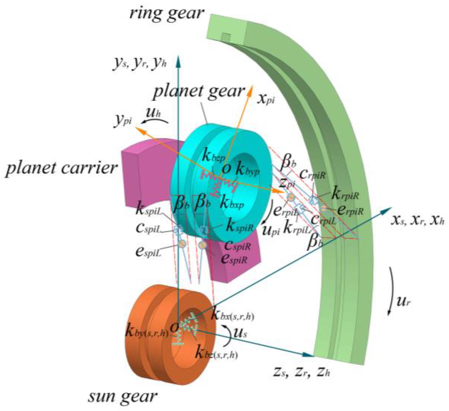
The centralized parameter method is used, and the coupling between the fixed-axis train and the differential train is considered to establish the dynamic model of the two-stage tandem hybrid planetary system. The schematic diagram of the differential train model is shown in Figure 2, with detailed parameters shown in the reference [9].
In this model, the sun gear, planet gear, ring gear and planet carrier are assumed to be rigid, and the meshing of the gears is represented by linear springs acting on the tooth surfaces. The time-varying component of the mesh stiffness due to the variation in the meshing tooth pairs is neglected, and the average mesh stiffness is used to calculate the contact between the tooth surfaces.
Using the Lagrange’s equations, the motion equations for a two-stage tandem hybrid planetary system can be written as:
M q ¨ ( t ) + C q ˙ ( t ) + [ K b + K m ( t ) ] q ( t ) = F t ,
where q is the generalized coordinate vector including transverse, axial and torsional motions; M is the mass matrix; C is the damping matrix; Kb is the bearing support stiffness matrix; Km is the mesh stiffness matrix; and Ft is the vector of internal and external excitation forces due to the combined drive and load moments and mesh errors.
q ¨ = [ x j , y j , z j , θ z j ]   ( j = a ,   dL ,   dR ,   m1 , ,   m3 ,   s ,   h ,   rL ,   rR ,   p1 , , p3 )
M = d i a g [ M j , M j , M j , J j ]   ( j = a ,   dL ,   dR ,   m1 , ,   m3 ,   s ,   h ,   rL ,   rR ,   p1 , , p3 )
where xj, yj, zj, and θzj represent the displacements of component j in the transverse direction, axial direction and torsional direction, respectively. Mj is the mass matrix of component j.
C = C a   C d L   C d R   C m   C s   C h   C r L   C r R   C p ,
K = K b + K m = K a   K d L   K d R   K m   K s   K h   K r L   K r R   K p ,

3. Mode Analysis

According to the dynamic model of the system, the undamped free vibration equation is obtained as follows:
M q ¨ ( t ) + [ K b + K m ( t ) ] q ( t ) = 0 ,
The dynamic equation corresponds to the characteristic equation:
[ ( K b + K m ) w i 2 M ] ϕ i = 0 ,
where wi is the i-th order natural frequency and ϕ i is the i-th order mode.
To quantify the mode sensitivity, the frequency shift between the two extreme cases is calculated as follows [17]:
f r e q u e n c y       s h i f t ( % ) = w i w f w i × 100 ,
where wi and wf represent the initial and final natural frequencies.
All planets have the same model parameters in the fixed-axis train and the differential train. Table 1 lists the main system parameters. Using numerical methods, the natural frequencies and vibration modes can be calculated (the tables are in Appendices). The vibration modes of the system can be categorized into three types: (1) fixed-axis train vibration mode; (2) differential train vibration mode; (3) coupled vibration mode.

3.1. Fixed-Axis Train Vibration Mode

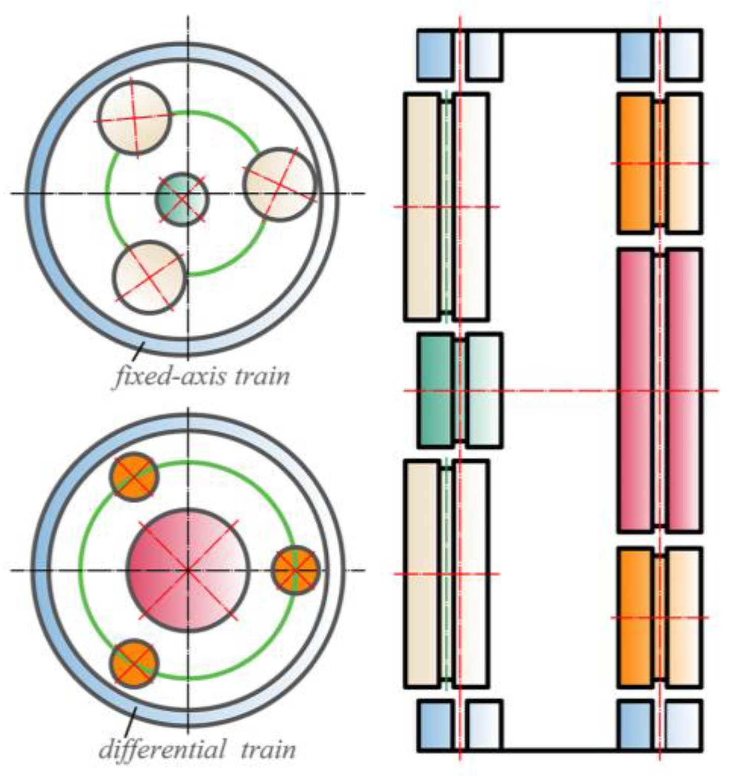
The fixed-axis vibration mode satisfies the following characteristics:
(1) The vibration displacements of the sun gear, ring gear, planet gears and planet carrier in the differential train are zero.
(2) The corresponding multiple roots of the natural frequency are 2, with a total of 7 pairs.
(3) The fixed-axis train has no axial and torsional motion, and the vibration modes of the central component corresponding to the frequencies ϕ i and ϕ ¯ i are:
p j = [ x j , y j , 0 , 0 ] , p ¯ j = [ y j , x j , 0 , 0 ] , j = ( a , d L , d R ) ,
The corresponding planet gear vibration modes have the following relationships:
p m n p ¯ m n = cos ψ n I sin ψ n I sin ψ n I cos ψ n I p m 1 p ¯ m 1 ,
The vibration modes can be expressed in the following form:
ϕ i = [ p a   , p d L ,     p d R ,     cos ψ 1 p m 1 sin   ψ 1 p ¯ m 1 , , cos ψ n p m 1 sin   ψ n p ¯ m 1   ]   T ϕ ¯ i = [ p ¯ a   , p ¯ d L ,     p ¯ d R ,     sin ψ 1 p m 1 + cos   ψ 1 p ¯ m 1 , , sin ψ n p m 1 + cos   ψ n p ¯ m 1 ]   T ,
A schematic diagram of the fixed-axis train vibration mode is given in Figure 3.

3.2. Differential Train Vibration Mode

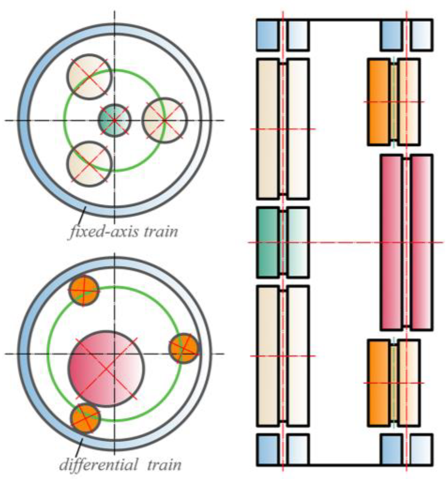
Similar to the fixed-axis train, the differential train vibration mode satisfies the following characteristics:
(1) The vibration displacements of the sun gear, ring gear and planet gears in the fixed-axis train are zero.
(2) The corresponding multiple roots of the natural frequency are 2, with a total of 8 pairs.
(3) The differential train has no axial and torsional motion, and the vibration modes of the central components corresponding to the frequencies ϕ i and ϕ ¯ i are:
p j = [ x j , y j , 0 , 0 ] , p ¯ j = [ y j , x j , 0 , 0 ] , j = ( s , r L , r R , h ) ,
The corresponding planet gear vibration modes have the following relationships:
p p n p ¯ p n = cos ψ n I sin ψ n I sin ψ n I cos ψ n I p p 1 p ¯ p 1 ,
where I is the 3rd-order unit matrix.
The vibration modes can be expressed in the following form:
ϕ i = [ p s   , p r L ,     p r R ,     p h , cos ψ 1 p p 1 sin   ψ 1 p ¯ p 1 , , cos ψ n p p 1 sin   ψ n p ¯ p 1   ]   T ϕ ¯ i = [ p ¯ s   , p ¯ r L ,     p ¯ r R ,     p ¯ h ,     sin ψ 1 p p 1 + cos   ψ 1 p ¯ p 1 , , sin ψ n p p 1 + cos   ψ n p ¯ p 1 ]   T ,
A schematic diagram of the differential train vibration mode is given in Figure 4.

3.3. Coupled Vibration Mode

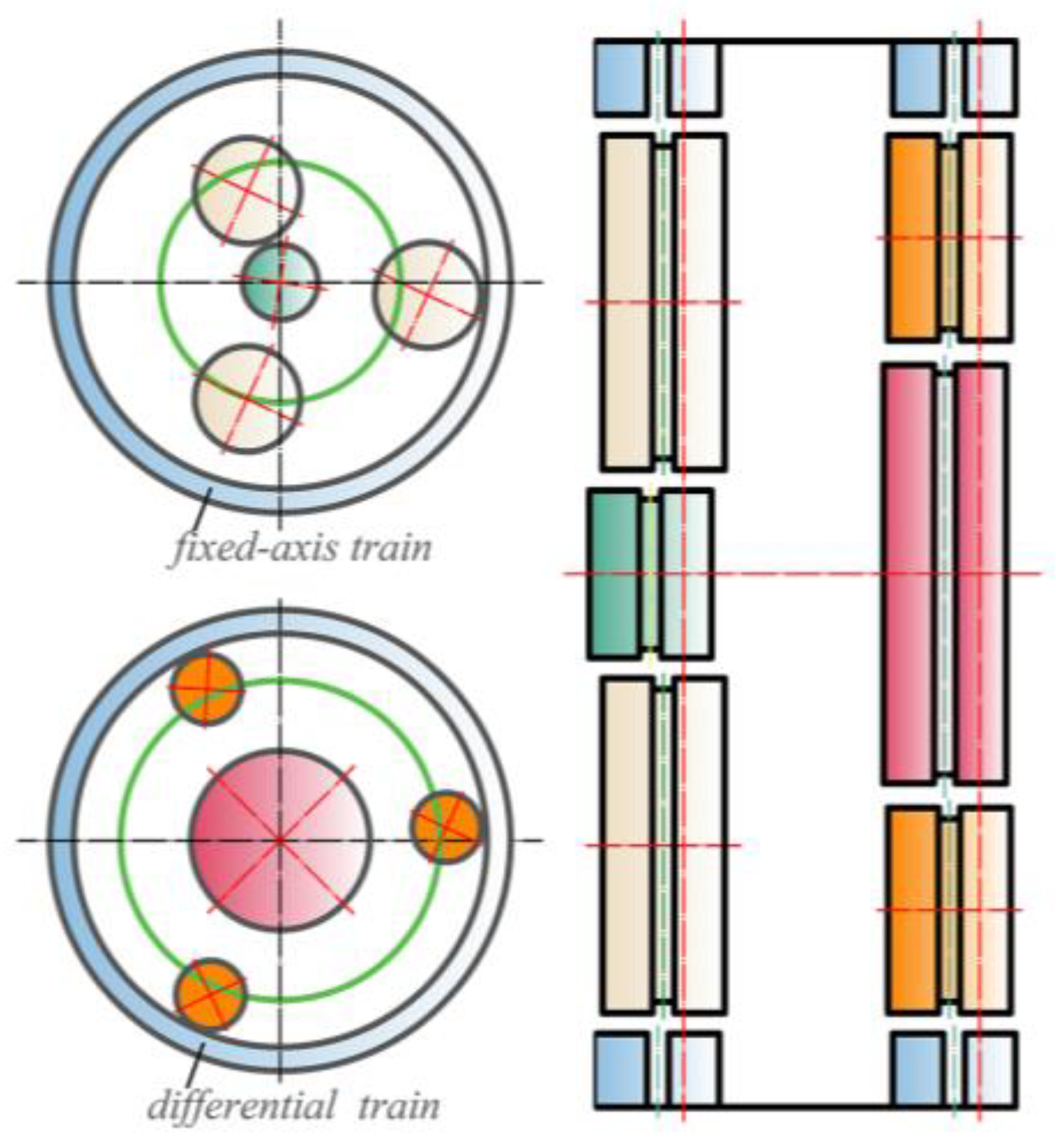
The coupled vibration mode satisfies the following characteristics:
(1) The corresponding natural frequencies are single roots, with a total of 22.
(2) There are no transverse motions of the central components in the fixed-axis train and the differential train, and the vibration modes of the respective planet gears in the two systems are the same.
(3) The coupled vibration modes include a planet carrier axial vibration mode and ring gears torsional vibration mode, corresponding to the number of natural frequencies of 1 and 2, respectively, which also satisfy the characteristics of the coupled vibration modes and can be regarded as a special coupled vibration mode.
The vibration modes of the central components are as follows:
p j = [ 0 , 0 , z j , θ z j ] j = ( a , d L , d R , s , r L , r R , h ) ,
The planet gear vibration modes have the following relationship:
p m n = p m 1 = [ x m 1 , y m 1 , z m 1 , θ z m 1 ] , p p n = p p 1 = [ x p 1 , y p 1 , z p 1 , θ z p 1 ] ,
The vibration modes can be expressed in the following form:
ϕ i = [ p a   , p d L ,   p d R , p m 1 , , p m n , p s   , p r L ,   p r R ,   p h , p p 1 , , p p n ] T ,
A schematic diagram of the coupled vibration mode is given in Figure 5.

3.4. Verification of the Mathematical Model Using the Finite Element Method

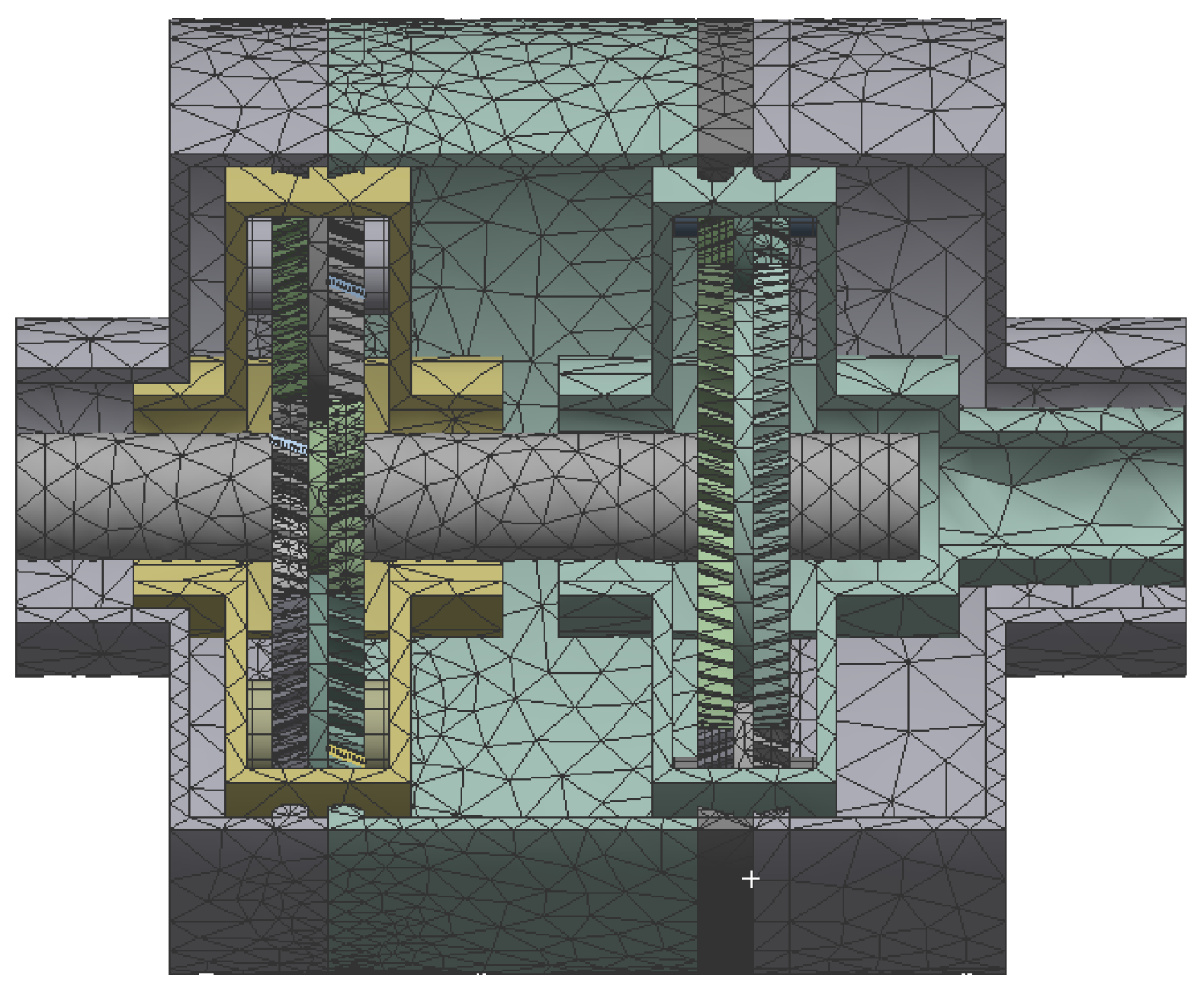
Reference [22] utilized the finite element method to calculate the natural frequencies of the 2K-H planetary gear system and compared the results with a mathematical model. To validate the mathematical model of the paper, a finite element model was employed. Based on the parameters in Table 1, the transmission system was accurately modeled using the three-dimensional modeling software Solidworks(2018). Subsequently, ANSYS Workbench(2020) was utilized for mesh generation, dividing the transmission system into a total of 131,027 nodes and 56,674 elements. Appropriate boundary and loading conditions were set, as shown in Figure 6. The first six vibration modes were extracted, and the obtained vibration modes and frequencies are presented in Table 2.
Table 2 reveals that, among the first six natural frequencies, the maximum difference between the finite element model and the mathematical model is 4.8%. The obtained vibration types are also consistent. Therefore, the finite element analysis results are in good agreement with the mathematical model, validating the effectiveness of the mathematical model.

4. Sensitivity Analysis of Natural Frequency

The study of the sensitivity of the natural frequencies to the system parameters can provide an important basis for the reduction in the system response and the optimization of the structural design. The sensitivity analysis of natural frequencies focuses on the effect of gear parameters on natural frequencies and vibration modes. The parameters include unequally spaced planet, mesh stiffness, planet mass and rotational inertia.
The characteristic sensitivity of the free vibration of the system shown in Equation (7) can be obtained by the following expressions:
(1) When the eigenvalue is a single root, the eigenvalue sensitivity is given by
λ i = ϕ i T ( K λ i M ) ϕ i ,
(2) When the eigenvalue is a repeated root, the eigenvalue sensitivity can be obtained by solving for the eigenvalue of the following equation:
D a i = λ i a i , D = Γ T ( K λ i M ) Γ ,
where Γ represents a set of m-dimensional vectors, m is the number of repeated roots, and the following relationship holds:
Γ T M Γ = I m × m ,
ϕ i = Γ a i

4.1. Unequally Spaced Planets

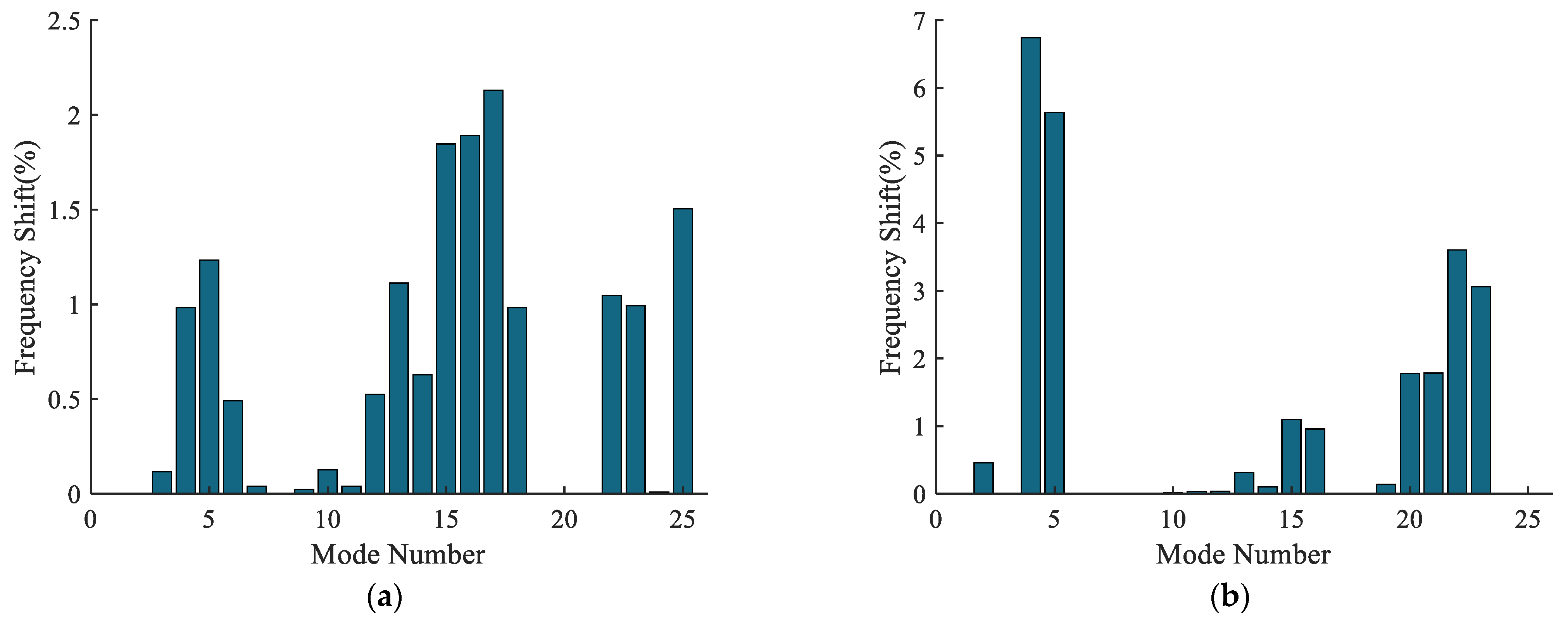
For the convenience of the study, the deviation angle of the first planet gear from its original position in the fixed-axis train and differential train was set to range from 0° to 15°, respectively. The frequency shifts of the first 25 modes were calculated, as shown in Table 3. The sensitivity of the first 25 natural frequencies to the inequality is shown in Figure 7. The frequency shifts for deviation angle = 0° and deviation angle = 15° are shown in Figure 8.
From Table 3 and Figure 6 and Figure 7, it can be seen that when the planet gears of the fixed-axis train and the differential train are unequally spaced, the first 25 natural frequencies are not very sensitive to the deviation angles. The maximum frequency shift is not more than 7% in both unequally spaced planets. However, it can be observed from Table 3 that the change in vibration modes is large. When the planet gear of the fixed-axis train is unequally spaced, except for the 8th-order planet carrier axial vibration mode, which remains unchanged, the vibration modes are transformed into global vibration modes. (In this vibration mode, vibration may exist in all directions with no obvious pattern.) When the planet gear of the differential train is unequally spaced, except for the 8th-order planet carrier axial vibration mode, the 6th-, 7th- and 17th- and 18th-order fixed-axis train vibration modes remain unchanged, and the rest of the vibration modes are transformed into the coupled–global vibration modes. (In this vibration mode, the fixed-axis train maintains the characteristics of the original coupling vibration mode, and the vibration of the gears of the differential train may be found in all directions without any obvious pattern.)
Since the unequally spaced planets break the cyclic symmetry of the two-stage tandem hybrid planetary system, the vibration modes are no longer easy to summarize, and new global vibration modes and coupled–global vibration modes appear. The unequally spaced planet in a fixed-axis gear train is more serious in damaging the vibration modes than that in a differential gear train. Because the latter still retains part of the original vibration pattern, the former is in addition to the planet carrier axial vibration mode; the vibration modes of the rest orders are changed to irregular global vibration modes.
In conclusion, the change in the natural frequencies caused by unequally spaced planets is very small, but the breakup of the vibration modes is more serious, and new global vibration modes and coupled–global vibration modes appear.

4.2. Mesh Stiffness

This section focuses on the influence of the mesh stiffness of sun gear–planet gear on the modes in the two-stage tandem hybrid planetary system. It is mainly divided into mesh stiffness sensitivity analysis and mode transition.

4.2.1. Mesh Stiffness Sensitivity Analysis

Taking the meshing stiffness of the sun gear–planet gear in the fixed-axis train kam as an example, the sensitivity of the natural frequencies to the meshing stiffness was studied. It is categorized into the following cases:
(1) Fixed-axis train vibration mode.
In the fixed-axis gear train vibration mode, the eigenvalues are multiple roots. Let the two eigenvalues be λ1, λ2 and λ = w2, which are the eigenvalues of the matrix D. D is given by the following formula:
D = Γ T K Γ = n = 1 N [ ( δ a m n ) 1 ] 2 ( δ a m n ) 1 ( δ a m n ) 2 ( δ a m n ) 1 ( δ a m n ) 2 [ ( δ a m n ) 2 ] 2 ,
where δamn is the relative displacement between the n-th planet gear m and the sun gear a.
(2) Differential train vibration mode.
In the differential train vibration mode, δamn = 0, so the sensitivity of the natural frequencies is zero.
(3) Coupled vibration mode.
In the coupled vibration mode, the eigenvalues are single roots, and the deformations of each planet gear are the same:
λ i = N [ ( δ a m 1 ) i ] 2 ,
Similarly, the sensitivity of the natural frequencies to the mesh stiffness of sun gear–planet gear in the differential train ksp can be obtained, which is similar to the above derivation and is not repeated here.
Briefly, with the change in kam, the natural frequencies of the fixed-axis train vibration mode and the coupled vibration mode change, while the frequencies of the differential train vibration mode remain unchanged. With the change in ksp, the frequencies of the differential train vibration mode and coupled vibration mode change, while the frequencies of the fixed-axis train vibration mode remain unchanged.

4.2.2. Mode Transition Criterion

When the system parameters are changed, the natural frequency curves approach gradually and then separate rapidly with a large curvature at a very close distance, a phenomenon known as mode transition [14]. Take kam as an example to study the mode transition of natural frequency to mesh stiffness. It is categorized into the following cases:
(1) The corresponding modes of λr and λs are both fixed-axis train vibration modes.
In this case, both λr and λs are double roots, λr = λp and λs = λq, and the coupling factors are calculated as follows:
χ r = χ p = χ s = χ q = 2 N 2 λ r λ s [ ( ( δ a m 1 ) r ( δ a m 1 ) s ) 2 + ( ( δ a m 1 ) r ( δ a m 1 ) q ) 2 + ( ( δ a m 1 ) p ( δ a m 1 ) s ) 2 + ( ( δ a m 1 ) p ( δ a m 1 ) q ) 2 ] ,
When the coupling factor is 0, the natural frequencies undergo a mode transition; otherwise, they intersect. Bringing in the characteristics of the fixed-axis train vibration mode, it can be seen that the coupling factor can not be 0. Therefore, the natural frequencies, in this case, transition.
(2) The corresponding modes of λr and λs are both differential train modes.
In the differential train vibration mode, the fixed-axis train does not vibrate, the natural frequencies have zero sensitivity to kam, and the trajectories of natural frequencies are straight lines. Therefore, the natural frequencies will not transition and intersect when kam changes.
(3) The corresponding modes of λr and λs are coupled vibration modes.
In this case, both λr and λs are single roots, and the coupling factors are calculated as follows:
χ r = 2 ( N ( δ a m 1 ) r ( δ a m 1 ) s ) 2 λ r λ s = χ s ,
Bringing in the characteristics of the coupled vibration mode, it can be seen that the coupling factors cannot be 0. Therefore, the natural frequencies, in this case, transition.
(4) λr belongs to the differential train vibration mode.
In this case, there is δamn = 0. Therefore, the natural frequencies under the differential train vibration mode intersect with those under other vibration modes.
(5) λr belongs to the coupled vibration mode, and λs belongs to the fixed-axis train vibration mode.
In this case, λs are double roots, λs = λq, and the coupling factors are calculated as follows:
χ s = 2 λ s λ r ( n = 1 N ( δ a m n )   s ( δ a m n )   r ) 2   χ q = 2 λ s λ r ( n = 1 N ( δ a m n )   q ( δ a m n )   r ) 2   χ r = ( χ s + χ q ) ,
Bringing in the characteristics of the two vibration modes shows that χ r = χ s = χ q = 0 holds true, and therefore, the natural frequencies intersect.
Similarly, the mode transition criterion of the natural frequencies to ksp can be obtained. The obtained mode transition criterion is summarized as shown in Table 4.

4.2.3. Sensitivity and Modal Transition Verification

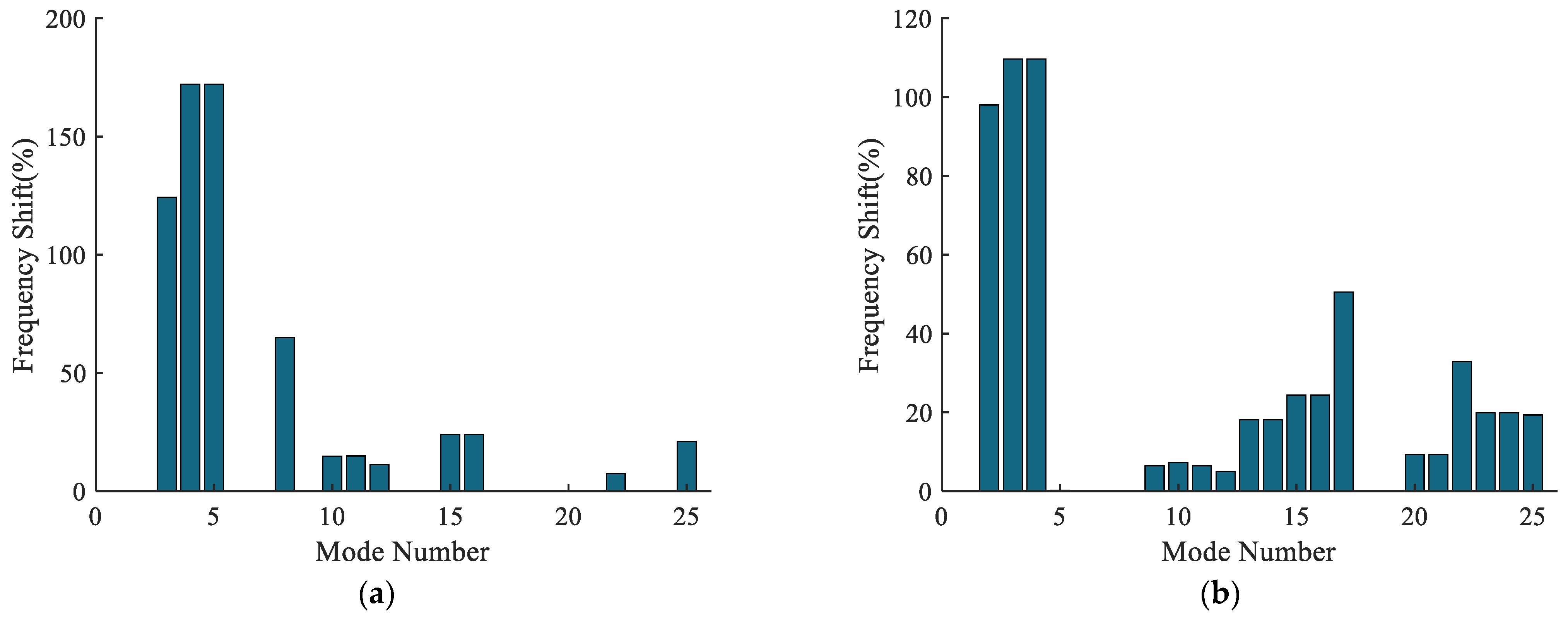
The kam and ksp were set to be from 107 N/m to 108 N/m, respectively. The frequency shifts of the first 25 modes were calculated, as shown in Table 5. The sensitivity of the first 25 natural frequencies to the mesh stiffness is shown in Figure 9, and the frequency shifts for mesh stiffness of 107 N/m and 108 N/m are shown in Figure 10.
From Table 5 and Figure 8 and Figure 9, it can be seen that the influence of the mesh stiffness of the sun gear–planet gear on the natural frequencies is very large, and the frequency shift even reaches 172.09%. When kam changes, the vibration modes corresponding to the changed natural frequencies are fixed-axis train vibration mode and coupled vibration mode; when ksp changes, the vibration modes corresponding to the changed natural frequencies are differential train vibration mode and coupled vibration mode. This also verifies the sensitivity of the natural frequencies to the mesh stiffness in Section 4.2.1. Since there are more differential train vibration modes than fixed-axis train vibration modes in the first 25 modes, although the peak frequency shift generated by kam is greater than that by ksp, its influence affects fewer orders than ksp.
The mode transition phenomenon can be observed in Figure 9, and the mode transition in Figure 9a is verified by comparing the mode transition criterion in Table 4. There is no case1 in Figure 9a; frequencies (13, 14) are a double root, belonging to the differential train vibration mode, which are straight lines, verifying case2; frequencies (11, 12) are two single roots, belonging to the coupled vibration mode, and the transitions occur at 5 × 10⁷ N/m, verifying case3; frequencies (15, 16) are a double root, belonging to the fixed-axis train vibration mode; frequency (19) is a single root, belonging to the coupled vibration mode, and intersections occur at 9 × 10⁷ N/m, verifying case4; there is no case5 in Figure 9a; frequencies (4, 5) are a double root, belonging to the fixed-axis train vibration mode, frequencies (6, 7) are a double root, belonging to the differential train vibration mode, and intersections occur at 2.5 × 10⁷ N/m, verifying case6. The mode transitions and intersections occurring at other positions in Figure 9a also conform to the mode transition criterion in Table 4, and similarly, the mode transitions and intersections in Figure 9b can be verified to conform to the mode transition criterion, which is not repeated here.
In conclusion, the mesh stiffness of the sun gear–planet gear mainly affects the natural frequencies of the system and does not change the original vibration modes. The mode transitions and intersections that occur are also consistent with the formulated mode transition criterion.

4.3. Planet Mass

The study of the sensitivity of the natural frequencies to the planet mass/rotational inertia is similar to the methodology of Section 4.2.1 and Section 4.2.2, which is not repeated here due to space implications. The mode transition criterion for the natural frequencies to the planet gear mass/rotational inertia is consistent with Table 4. The variation rule of the sensitivity of natural frequencies to planet mass/rotational inertia was obtained as follows:
As the planet gear mass Mm/rotational inertia Jm in the fixed-axis train changes, the natural frequencies of the fixed-axis train vibration mode and the coupled vibration mode change, while the natural frequencies of the differential train vibration mode remain unchanged. As the planet gear mass Mp/rotational inertia Jp in the differential train changes, the natural frequencies of the differential train vibration mode and the coupled vibration mode change, while the natural frequencies of the fixed-axis train vibration mode remain unchanged.
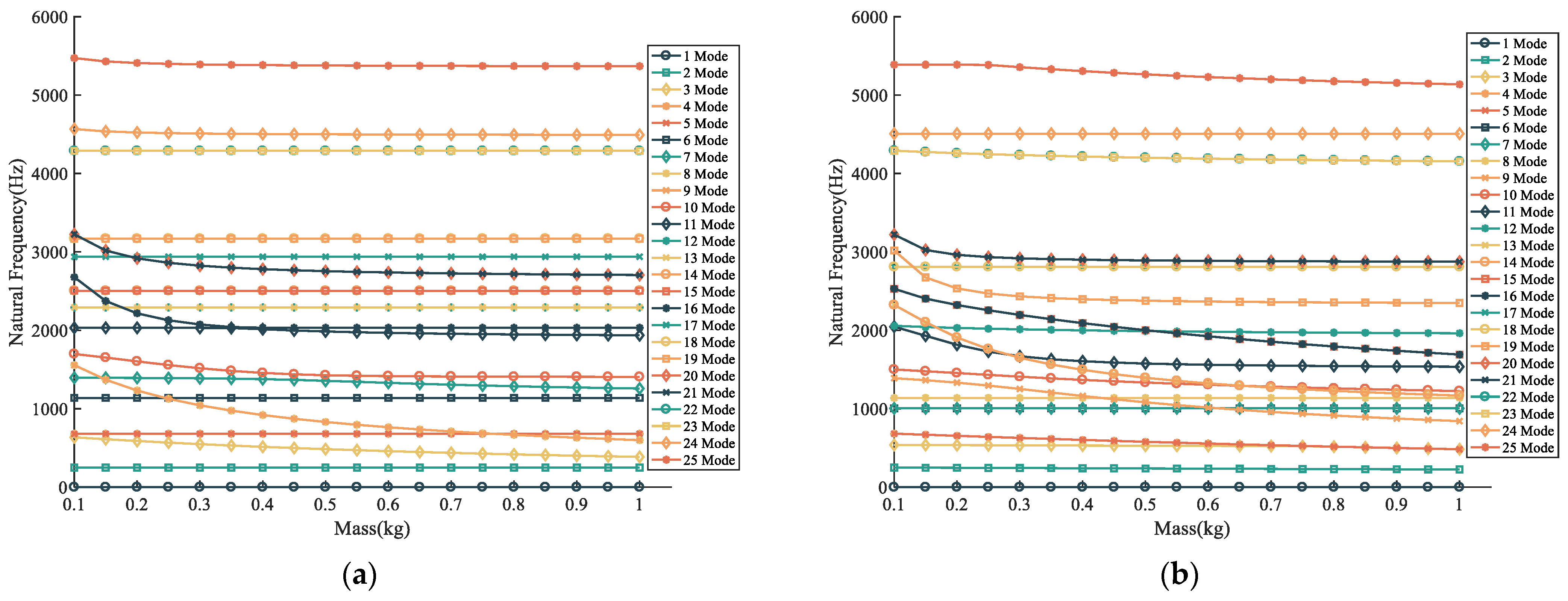
Setting Mm and Mp from 0.1 kg to 1 kg, respectively, the frequency shifts of the first 25 modes were calculated, as shown in Table 6. The sensitivity of the first 25 natural frequencies to the planet mass is shown in Figure 11, and the frequency shifts for planet mass of 0.1 kg and 1 kg are shown in Figure 12.
From Table 6 and Figure 11 and Figure 12, it can be seen that the effects of the planet mass on the natural frequencies are also very large, and the maximum value of the frequency shift reaches 61.47%. When Mm changes, the vibration modes corresponding to the changed natural frequencies are the fixed-axis train vibration mode and the coupled vibration mode; when Mp changes, the vibration modes corresponding to the changed natural frequencies are the differential train vibration mode and the coupled vibration mode. This also verifies the sensitivity of natural frequencies to the planet gear mass, as mentioned above. Similarly, the peak frequency shift generated by Mm is larger than that of Mp, but its influence affects fewer orders than Mp.
The mode transition phenomenon can be observed in Figure 11, and the mode transition in Figure 11a is verified by comparing the mode transition criterion in Table 4. There is no case1 in Figure 11a; frequencies (12, 13) are a double root, belonging to the differential train vibration mode, which are straight lines, verifying case2; frequencies (7, 10) are two single roots, belonging to the coupled vibration mode, and the transitions occur at 0.5 kg, verifying case3; frequencies (8, 9) are a double root, belonging to the fixed-axis train vibration mode, and frequency (6) is a single root, belonging to the coupled vibration mode, and intersections occur at 0.15 kg, verifying case4; frequency (16) is a single root, belonging to the coupled vibration mode, and it intersects with frequencies (12, 13) between 0.15 and 0.2 kg, which belong to the of the differential train vibration mode, verifying case 5; frequencies (4, 5) are a double root, belonging to the differential train vibration mode, and intersect with frequencies (8, 9) between 0.75 and 0.8 kg, which belong to the fixed-axis train vibration mode, verifying case6. The mode transitions and intersections occurring at other positions in Figure 11a also conform to the mode transition criterion in Table 4, and similarly, the mode transitions and intersections in Figure 11b can be verified to conform to the mode transition criterion in Table 4, which is not repeated here.

4.4. Planet Rotational Inertia

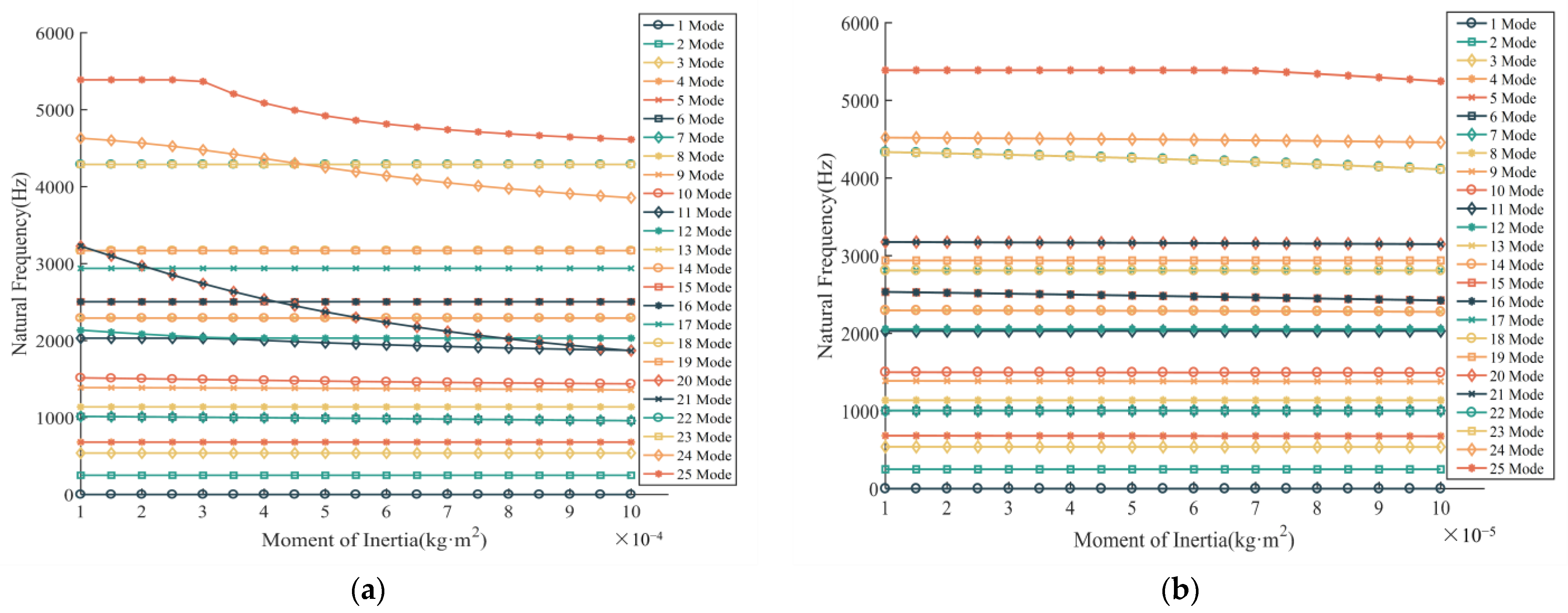
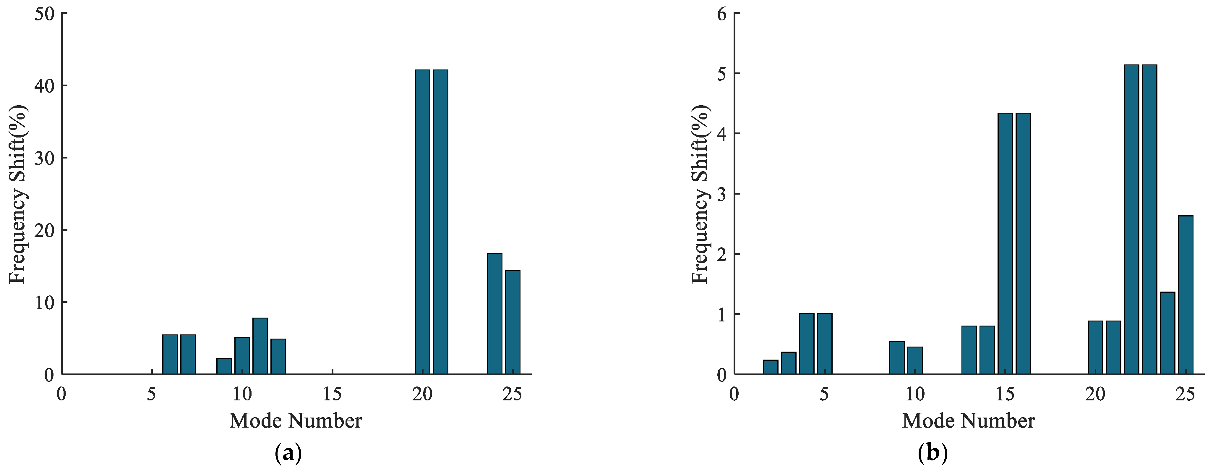
Setting Jm from 10−4 kg·m2 to 10−3 kg·m2 and Jp from 10−5 kg·m2 to 10−4 kg·m2, the frequency shifts of the first 25 modes were calculated, as shown in Table 7. The sensitivity of the first 25 natural frequencies to the planet rotational inertia is shown in Figure 13, and the frequency shifts for extreme values of the rotational inertia are shown in Figure 14.
From Table 7 and Figure 12 and Figure 13, it can be observed that due to Jm being an order of magnitude larger than Jp, the selected range for Jm also varies significantly. Within the chosen range of rotational inertia, the maximum frequency shift caused by Jm reaches 42.12%, while the maximum frequency shift caused by Jp is only 5.14%. As the rotational inertia changes, the sensitivity of the natural frequencies to the planet rotational inertia follows the expected rules as discussed earlier. Similarly, the order of occurrence frequency shift affected by Jm is less than that of Jp.
The mode transition phenomenon can be observed in Figure 13, and the mode transition in Figure 13a is verified by comparing the mode transition criterion in Table 4. There is no case1 in Figure 13a; frequencies (4, 5) are a double root, belonging to the differential train vibration mode, which are straight lines, verifying case2; frequencies (11, 12) are two single roots, belonging to the coupled vibration mode, and the transition occurs at 3.5 × 10⁻⁴ kg·m2, verifying case3; frequencies (20, 21) are a double root, belonging to the fixed-axis train vibration mode, frequency (12) is a single root, belonging to the coupled vibration mode, and intersections occur between 7.5 × 10⁻⁴ and 8 × 10⁻⁴ kg·m2, verifying case4; frequency (24) is a single root, belonging to the coupled vibration mode, frequencies (22, 23) are a double root, belonging to the vibration mode of the differential train, and intersections occur between 4.5 × 10⁻⁴ and 5 × 10⁻⁴ kg·m2, verifying case5; frequencies (13, 14) are a double root, belonging to the differential train vibration mode, and intersect with frequencies (20, 21) between 5.5 × 10⁻⁴ and 6 × 10⁻⁴ kg·m2, which belonging to the fixed-axis train vibration mode, verifying case6. The mode transitions and intersections occurring at the other positions in Figure 13a also conform to the mode transition criterion in Table 4. Within the selected mass range, the range of natural frequency variations in Figure 13b is small and does not reach the point where mode transitions and intersections occur.

5. Conclusions

Based on the centralized parameter model of the two-stage tandem hybrid planetary system, the natural characteristics were analyzed; three typical vibration modes were summarized; and the sensitivity of natural frequencies to unequally spaced planet, mesh stiffness, planet mass and rotational inertia, as well as the mode transition and intersection phenomena of natural frequencies under the influence of different parameters, were investigated.
(1) The vibration modes of the two-stage tandem hybrid planetary system include fixed-axis train vibration mode, differential train vibration mode and coupled vibration mode.
(2) The sensitivity of the natural frequencies to the parameters was investigated. With the change in the parameters in the fixed-axis train, the natural frequencies of the fixed-axis train vibration mode and the coupled vibration mode change, while the natural frequencies of the differential train vibration mode remain unchanged. With the change in parameters in the differential train, the natural frequencies of the differential train vibration mode and coupled vibration mode change, while the natural frequencies of the fixed-axis train vibration mode remain unchanged. Combined with the numerical examples, the correctness of the parameter sensitivity was verified, and the frequency shifts under the influence of different parameters were calculated.
(3) The mode transition phenomenon was investigated, and the criterion for the occurrence of mode transition of the two-stage tandem hybrid planetary system was determined, and the accuracy of the proposed mode transition criterion was verified by calculations.
Through the model established in this study, natural characteristics of the marine two-stage tandem hybrid planetary system can be swiftly obtained, aiding design engineers in better comprehending the dynamic behavior of the gear system. This understanding facilitates design optimization to mitigate resonance and enhance system performance, reliability and longevity. Despite the close resemblance between the mathematical model presented in this paper and finite element results, disparities from reality persist. Therefore, future research endeavors could involve further refining the model, such as the coupling between the sun gear and the planet gears at their respective ends, which could be explored in detail, treating the entire assembly as flexible components, among other aspects. It is anticipated that such refinements will yield results closer to reality, representing our forthcoming focus and dedication.

Author Contributions

Conceptualization, X.Z. and Z.Y.; methodology, X.Z. and Z.Y.; software, J.Q.; validation, M.D. and Y.W.; formal analysis, Z.Y.; investigation, Z.Y.; resources, X.Z.; data curation, M.D.; writing—original draft preparation, Z.Y.; writing—review and editing, Z.Y.; visualization, Y.W.; supervision, Y.W.; project administration, Y.W; funding acquisition, Y.W. All authors have read and agreed to the published version of the manuscript.

Funding

This research was funded by the Technological Achievements Transformation Project, grant number CG21B010, and the Heilongjiang Provincial Nature Foundation research team project, grant number TD2023E002.

Data Availability Statement

The data presented in this study are available upon request from the corresponding author. The data are not publicly available due to laboratory regulations.

Conflicts of Interest

The authors declare no conflict of interest.

References

  1. Ambarisha, V.K.; Parker, R.G. Nonlinear dynamics of planetary gears using analytical and finite element models. J. Sound Vib. 2007, 302, 577–595. [Google Scholar] [CrossRef]
  2. Kahraman, A.; Blankenship, G.W. Interactions between commensurate parametric and forcing excitations in a system with clearance. J. Sound Vib. 1996, 194, 317–336. [Google Scholar] [CrossRef]
  3. Zhao, R.Z.; Liu, H.; Zheng, Y.Q. Parameter sensitivity for the torsional vibration of wind turbine drive train system. In Proceedings of the International Conference on Information Science and Intelligent Control, Shanghai, China, 24–25 April 2015; pp. 71–76. [Google Scholar]
  4. Zhang, L.; Wang, Y.; Wu, K.; Sheng, R.; Huang, Q. Dynamic modeling and vibration characteristics of a two-stage closed-form planetary gear train. Mech. Mach. Theory 2016, 97, 12–28. [Google Scholar] [CrossRef]
  5. Wu, X.; Parker, R.G. Mode characteristics of planetary gears with an elastic continuum ring gear. J. Appl. Mech. 2008, 75, 031014. [Google Scholar] [CrossRef]
  6. Sondkar, P.; Kahraman, A. A dynamic model of a double-helical planetary gear set. Mech. Mach. Theory 2013, 70, 157–174. [Google Scholar] [CrossRef]
  7. Hao, D.; Zhi, L.; Jian, Z. Inherent characteristic analysis of a dual power split gear train. IOP Conf. Ser. Earth Environ. Sci. 2019, 233, 032007. [Google Scholar] [CrossRef]
  8. Cui, T.; Li, Y.; Zan, C.; Chen, Y. Dynamic modeling and analysis of nonlinear compound planetary system. Machines 2022, 10, 31. [Google Scholar] [CrossRef]
  9. Shuai, M.; Ting, Z.; Guo-Guang, J.; Xiao-Lin, C.; Han-Jun, G. Analytical investigation on load sharing characteristics of her-ringbone planetary gear train with flexible support and floating sun gear. Mech. Mach. Theory 2020, 144, 103670. [Google Scholar] [CrossRef]
  10. Mbarek, A.; Hammami, A.; Del Rincon, A.F.; Chaari, F.; Rueda, F.V.; Haddar, M. Effect of load and mesh stiffness variation on mode characteristics of planetary gear. Appl. Acoust. 2019, 147, 32–43. [Google Scholar] [CrossRef]
  11. Cooley, C.G.; Parker, R.G. Vibration properties of high-speed planetary gears with gyroscopic effects. J. Vib. Acoust. 2012, 134, 061014. [Google Scholar] [CrossRef]
  12. Qiu, W.; Yang, F.; Wang, D.; Jiang, X. Design and free vibration characteristics of linkage planetary gear trains. J. Braz. Soc. Mech. Sci. Eng. 2022, 44, 58. [Google Scholar] [CrossRef]
  13. Liu, H.; Zhan, Z. Modal properties of a two-stage planetary gear system with a Timoshenko beam as the intermediate shaft model. Proc. Inst. Mech. Eng. Part D J. Automob. Eng. 2022, 236, 353–365. [Google Scholar] [CrossRef]
  14. Hu, Z.; Tang, J.; Wang, Q.; Chen, S.; Qian, L. Investigation of nonlinear dynamics and load sharing characteristics of a two-path split torque transmission system. Mech. Mach. Theory 2020, 152, 103955. [Google Scholar] [CrossRef]
  15. Huang, C.; Huang, B.; Zhang, Y.; Xiao, K. Modal analysis and experimental research on a planetary reducer with small tooth number difference. Trans. Can. Soc. Mech. Eng. 2019, 44, 202–212. [Google Scholar] [CrossRef]
  16. Hu, C.; Geng, G.; Liu, X.; Yang, S.; Tang, X. Dynamic Characteristics of the Multistage Planetary Gear Transmission System Based on a Stochastic Load. Int. J. Precis. Eng. Manuf. 2023, 24, 657–669. [Google Scholar] [CrossRef]
  17. Tatar, A.; Schwingshackl, C.W.; Friswell, M.I. Dynamic behaviour of three-dimensional planetary geared rotor systems. Mech. Mach. Theory 2019, 134, 39–56. [Google Scholar] [CrossRef]
  18. Tatar, A.; Schwingshackl, C.W.; Friswell, M.I. Modal sensitivity of three-dimensional planetary geared rotor systems to planet gear parameters. Appl. Math. Model. 2023, 113, 309–332. [Google Scholar] [CrossRef]
  19. Guo, Y.; Parker, R.G. Sensitivity of general compound planetary gear natural frequencies and vibration modes to model parameters. J. Vib. Acoust. 2010, 132, 11006. [Google Scholar] [CrossRef]
  20. Parker, R.G.; Wu, X. Vibration modes of planetary gears with unequally spaced planets and an elastic ring gear. J. Sound Vib. 2010, 329, 2265–2275. [Google Scholar] [CrossRef]
  21. Cooley, C.G.; Parker, R.G. Eigenvalue sensitivity and veering in gyroscopic systems with application to high-speed planetary gears. Eur. J. Mech.-A/Solids 2018, 67, 123–136. [Google Scholar] [CrossRef]
  22. Qian, P.-Y.; Zhang, Y.-L.; Cheng, G.; Ge, S.-R.; Zhou, C.-F. Model analysis and verification of 2K-H planetary gear system. J. Vib. Control 2015, 21, 1946–1957. [Google Scholar] [CrossRef]
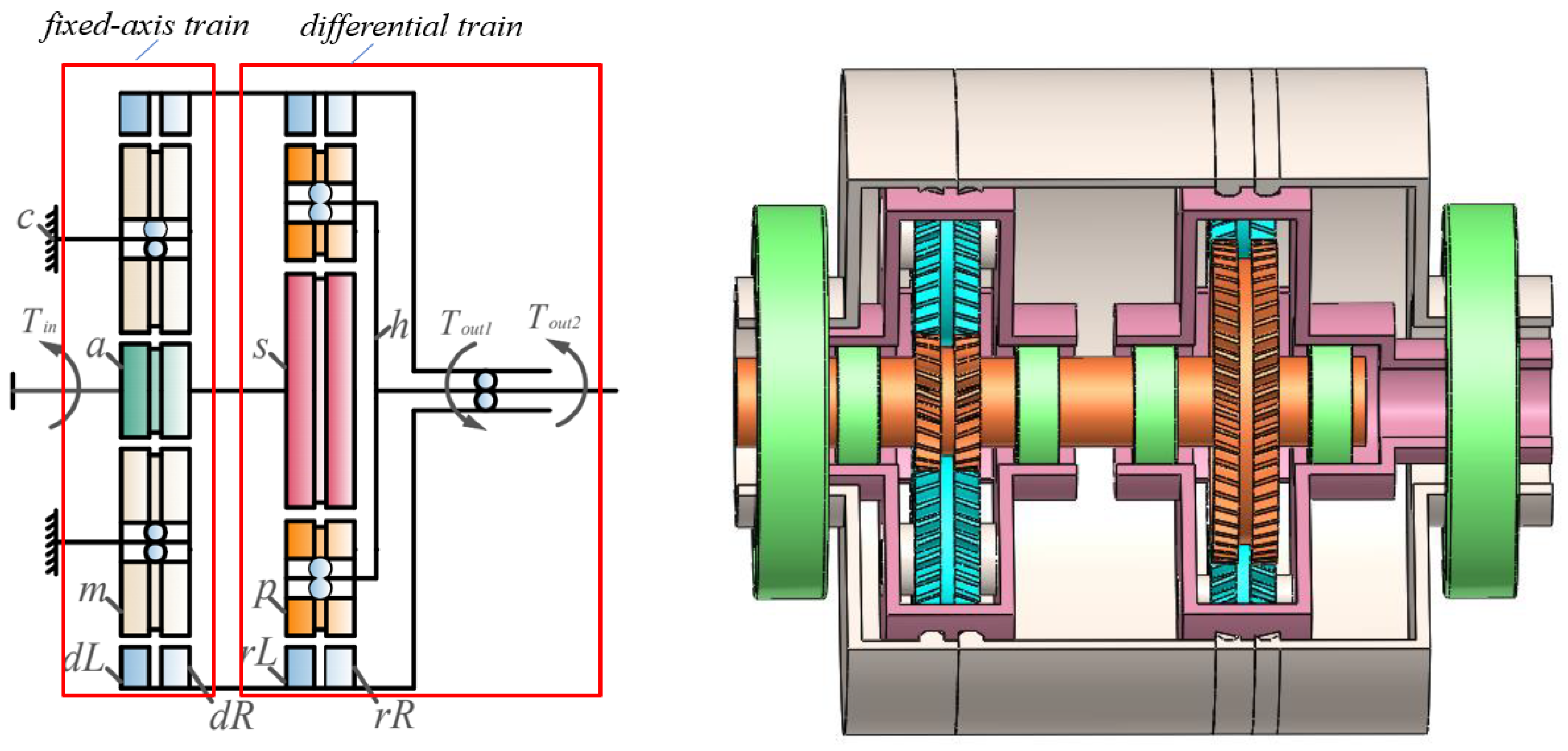
Figure 1. Schematic diagram of marine two-stage tandem hybrid planetary system.
Machines 12 00338 g001
Figure 2. Dynamic model of the differential train.
Machines 12 00338 g002
Figure 3. Fixed-axis train vibration mode.
Machines 12 00338 g003
Figure 4. Differential train vibration mode.
Machines 12 00338 g004
Figure 5. Coupled vibration mode.
Machines 12 00338 g005
Figure 6. The finite element model of the marine two-stage tandem hybrid planetary system.
Machines 12 00338 g006
Figure 7. Sensitivity of the first 25 natural frequencies to the unequally spaced planet: (a) unequally spaced planet of a fixed-axis train; (b) unequally spaced planet of a differential train.
Machines 12 00338 g007
Figure 8. Frequency shifts for deviation angle = 0° and deviation angle = 15°: (a) unequally spaced planet of a fixed-axis train; (b) unequally spaced planet of a differential train.
Machines 12 00338 g008
Figure 9. Sensitivity of the first 25 natural frequencies to the mesh stiffness: (a) kam; (b) ksp.
Machines 12 00338 g009
Figure 10. Frequency shifts for mesh stiffness of 107 N/m and 108 N/m: (a) kam; (b) ksp.
Machines 12 00338 g010
Figure 11. Sensitivity of the first 25 natural frequencies to the planet gear mass: (a) Mm; (b) Mp.
Machines 12 00338 g011
Figure 12. Frequency shifts for planet mass of 0.1 kg and 1 kg: (a) Mm; (b) Mp.
Machines 12 00338 g012
Figure 13. Sensitivity of the first 25 natural frequencies to the planet gear rotational inertia: (a) Jm; (b) Jp.
Machines 12 00338 g013
Figure 14. Frequency shifts for planet gear rotational inertia of extreme value. (a) Jm; (b) Jp.
Machines 12 00338 g014
Table 1. Parameters of the marine two-stage tandem hybrid planetary system.
ItemNumber of TeethAngle of Helix (°)Normal Pressure Angle (°)ModuleMass (kg)Rotational Inertia (kg·mm2)
Sun gear a2220201.50.09217.664
Planet gear m4420201.50.327268.521
Ring gear dL11020201.50.1631325.860
Ring gear dR11020201.50.1631325.860
Sun gear s5520201.50.488525.752
Planet gear p2720201.50.10835.531
Ring gear rL11020201.50.1631325.860
Ring gear rR11020201.50.1631325.860
Planet carrier h////1.6484946.014
Table 2. Comparison of vibration modes obtained from two models.
ModeMathematical Model
Nat. Freq. (Hz)
Finite Element Model
Nat. Freq. (Hz)
Difference (%)Mod Type
1000/
2249.96255.712.3couple
3538.75564.614.8couple
4680.52656.02−3.6differential train
5680.52656.02−3.6differential train
61005.471031.62.6fixed-axis train
Table 3. Vibration modes for planet gears are unequally spaced.
ModeDev. Ang. = 0°
Nat. Freq. (Hz)
Dev. Ang. = 0°
Mod Type
Fixed-Axis TrainDifferential Train
Dev. Ang. = 15°
Nat. Freq. (Hz)
Dev. Ang. = 15°
Mod Type
Freq. Shift(%)Dev. Ang. = 15°
Nat. Freq. (Hz)
Dev. Ang. = 15°
Mod Type
Freq. Shift (%)
10couple0global00couple–global0
2249.96couple249.96global0248.81couple–global0.46
3538.75couple538.12global0.12538.74couple–global0
4680.52differential train673.84global0.98634.64couple–global6.74
5680.52differential train688.91global1.23718.85couple–global5.63
61005.47fixed-axis train1000.53global0.491005.47fixed-axis train0
71005.47fixed-axis train1005.87global0.041005.47fixed-axis train0
81138.42planet carrier1138.42planet carrier01138.42planet carrier0
91385.93couple1385.6global0.021385.85couple–global0.01
101497.41couple1495.52global0.131497.12couple–global0.02
112030.67couple2029.86global0.042030.03couple–global0.03
122054.77couple2044global0.522053.98couple–global0.04
132292.34differential train2266.85global1.112285.13couple–global0.31
142292.34differential train2306.73global0.632294.74couple–global0.1
152504.67differential train2458.41global1.852477.16couple–global1.1
162504.67differential train2552.05global1.892528.65couple–global0.96
172809.75fixed-axis train2749.92global2.132809.75fixed-axis train0
182809.75fixed-axis train2837.37global0.982809.75fixed-axis train0
192938.39couple2938.39global02934.2couple–global0.14
203169.47differential train3169.39global03113.13couple–global1.78
213169.47differential train3169.55global03225.96couple–global1.78
224288.77differential train4243.9global1.054134.17couple–global3.6
234288.77differential train4331.34global0.994420.11couple–global3.06
244507.93couple4508.32global0.014508.21couple–global0.01
255388.32couple5307.26global1.55388.33couple–global0
Table 4. Mode transition criterion of natural frequency to mesh stiffness.
Vibration ModeMeshing Stiffness kam
Mode Transition Criterion
Meshing Stiffness ksp
Mode Transition Criterion
Case1All vibration modes are fixed-axis train vibration modestransitionunchange
Case2All vibration modes are differential train vibration modesunchangetransition
Case3All vibration modes are coupled vibration modestransitiontransition
Case4Vibration modes are coupled vibration mode and fixed-axis train vibration modeintersectintersect
Case5Vibration modes are coupled vibration mode and differential train vibration modeintersectintersect
Case6Vibration modes are fixed-axis train vibration mode and differential train vibration modeintersectintersect
Table 5. Vibration modes under variation in mesh stiffness.
ModeFixed-Axis TrainDifferential Train
kam = 107 N/m
Nat. Freq. (Hz)
kam =108 N/m
Nat. Freq. (Hz)
Mod TypeFreq. Shift (%)ksp =107 N/m
Nat. Freq. (Hz)
ksp =108 N/m
Nat. Freq. (Hz)
Mod TypeFreq. Shift (%)
100couple000couple0
2249.74249.97couple0.09142.13281.43couple98.01
3280.62629.29couple124.25375.67787.68differential train109.67
4479.391304.38fixed-axis train172.09375.67787.68differential train109.67
5479.391304.38fixed-axis train172.09537.79538.86couple0.2
6680.52680.52differential train01005.471005.47differential train0
7680.52680.52differential train01005.471005.47differential train0
8845.651394.85couple64.941138.421138.42planet carrier0
91138.421138.42planet carrier01311.121395.07couple6.4
101403.531611.29couple14.81405.051508.04couple7.33
111768.452031.44couple14.871916.282040.61couple6.49
122031.582259.49couple11.221972.242071.08couple5.01
132292.342292.34differential train02049.222420.15differential train18.1
142292.342292.34differential train02049.222420.15differential train18.1
152399.262973.19fixed-axis train23.922129.582648.16differential train24.35
162399.262973.19fixed-axis train23.922129.582648.16differential train24.35
172504.672504.67differential train02322.193495.13couple50.51
182504.672504.67differential train02809.752809.75differential train0
192938.382938.39couple02809.752809.75differential train0
203169.473169.47differential train03057.453341.41differential train9.29
213169.473169.47differential train03057.453341.41differential train9.29
224265.824581.29couple7.43392.914509.21couple32.9
234288.774288.77differential train03756.924503.96differential train19.88
244288.774288.77differential train03756.924503.96differential train19.88
254593.95557.98couple20.994514.165388.37couple19.37
Table 6. Vibration modes under variation in planet mass.
ModeFixed-Axis TrainDifferential Train
Mm = 0.1 kg
Nat. Freq. (Hz)
Mm = 1 kg
Nat. Freq. (Hz)
Mod TypeFreq. Shift (%)Mp = 0.1 kg
Nat. Freq. (Hz)
Mp = 1 kg
Nat. Freq. (Hz)
Mod TypeFreq. Shift (%)
100couple000couple0
2249.96249.96couple0250.2225.68couple9.8
3635.37385.58couple39.31538.98483.77couple10.24
4680.52680.52differential train0682.74483.77differential train29.14
5680.52680.52differential train0682.74483.77differential train29.14
61138.421138.42planet carrier01005.471005.47fixed-axis train0
71395.161257.79couple9.851005.471005.47fixed-axis train0
81556.41599.63fixed-axis train61.471138.421138.42planet carrier0
91556.41599.63fixed-axis train61.471389.59842.26couple39.39
101698.551406.46couple17.21500.941225.51couple18.35
112031.741936.78couple4.672047.011536.29couple24.95
122292.342292.34differential train02058.291962.92couple4.63
132292.342292.34differential train02324.641168.2differential train49.75
142504.672504.67differential train02324.641168.2differential train49.75
152504.672504.67differential train02529.831691.2differential train33.15
162678.122031.99couple24.132529.831691.2differential train33.15
172938.392938.39couple02809.752809.75fixed-axis train0
183169.473169.47differential train02809.752809.75fixed-axis train0
193169.473169.47differential train03017.752348.77couple22.17
203224.872705.55fixed-axis train16.13221.62875.26differential train10.75
213224.872705.55fixed-axis train16.13221.62875.26differential train10.75
224288.774288.77differential train04291.784154.75differential train3.19
234288.774288.77differential train04291.784154.75differential train3.19
244567.24492.48couple1.644507.934507.88couple0
255472.185368.31couple1.95388.335137.52couple4.65
Table 7. Vibration modes under variation in planet rotational inertia.
ModeFixed-Axis TrainDifferential Train
Jm = 0.1 kg
Nat. Freq. (Hz)
Jm = 1 kg
Nat. Freq. (Hz)
Mod TypeFreq. Shift (%)Jp = 0.1 kg
Nat. Freq. (Hz)
Jp = 1 kg
Nat. Freq. (Hz)
Mod TypeFreq. Shift (%)
100couple000couple0
2249.97249.94couple0.01250.18249.59couple0.24
3538.76538.73couple0.01539.47537.49couple0.37
4680.52680.52differential train0682.46675.56differential train1.01
5680.52680.52differential train0682.46675.56differential train1.01
61014.34959.12fixed-axis train5.441005.471005.47fixed-axis train0
71014.34959.12fixed-axis train5.441005.471005.47fixed-axis train0
81138.421138.42planet carrier01138.421138.42couple0
91389.051358.09couple2.231388.531380.97couple0.54
101516.171438.54couple5.121499.921493.13couple0.45
112031.351872.99couple7.82030.72030.61couple0
122135.992031.66couple4.882054.822054.66couple0.01
132292.342292.34differential train02295.322276.9differential train0.8
142292.342292.34differential train02295.322276.9differential train0.8
152504.672504.67differential train02534.012424.1differential train4.34
162504.672504.67differential train02534.012424.1differential train4.34
172938.392938.39couple02809.752809.75fixed-axis train0
183169.473169.47differential train02809.752809.75fixed-axis train0
193169.473169.47differential train02938.392938.39couple0
203227.441868.08fixed-axis train42.123176.613148.44differential train0.89
213227.441868.08fixed-axis train42.123176.613148.44differential train0.89
224288.774288.77differential train04334.674111.9differential train5.14
234288.774288.77differential train04334.674111.9differential train5.14
244630.253855.18couple16.744520.84459.12couple1.36
255388.484613.61couple14.385388.385246.58couple2.63
Disclaimer/Publisher’s Note: The statements, opinions and data contained in all publications are solely those of the individual author(s) and contributor(s) and not of MDPI and/or the editor(s). MDPI and/or the editor(s) disclaim responsibility for any injury to people or property resulting from any ideas, methods, instructions or products referred to in the content.